12596
30
Verklein
Vergroot
Pagina terug
1/32
Pagina verder
INSTRUCTION MANUAL
iM2A
VHF MARINE TRANSCEIVER
This device complies with Part 15 of the FCC Rules. Operation is sub-
ject to the follow two conditions: (1) This device may not cause harmful
interference, and (2) this device must accept any interference received,
including interference that may cause undesired operation.
SAFETY TRAINING INFORMATION
Your Icom radio generates RF electromagnetic energy during
transmit mode. This radio is designed for and classified as
“Occupational Use Only”, meaning it must be used only dur-
ing the course of employment by individuals aware of the haz-
ards, and the ways to minimize such hazards. This radio is
NOT intended for use by the “General Population” in an un-
controlled environment.
This radio has been tested and complies with the FCC RF exposure limits for
“Occupational Use Only”. In addition, your Icom radio complies with the follow-
ing Standards and Guidelines with regard to RF energy and electromagnetic
energy levels and evaluation of such levels for exposure to humans:
• FCC OET Bulletin 65 Edition 97-01 Supplement C, Evaluating Compliance
with FCC Guidelines for Human Exposure to Radio Frequency Electro-
magnetic Fields.
American National Standards Institute (C95.1-1992), IEEE Standard for
Safety Levels with Respect to Human Exposure to Radio Frequency Elec-
tromagnetic Fields, 3 kHz to 300 GHz.
American National Standards Institute (C95.3-1992), IEEE Recommended
Practice for the Measurement of Potentially Hazardous Electromagnetic
Fields– RF and Microwave.
To ensure that your expose to RF electromagnetic en-
ergy is within the FCC allowable limits for occupational
use, always adhere to the following guidelines:
DO NOT operate the radio without a proper antenna at-
tached, as this may damaged the radio and may also cause
you to exceed FCC RF exposure limits. A proper antenna is the antenna sup-
plied with this radio by the manufacturer or antenna specifically authorized by
the manufacturer for use with this radio.
CAUTION
WARNING
DO NOT transmit for more than 50% of total radio use time (“50% duty
cycle”). Transmitting more than 50% of the time can cause FCC RF expo-
sure compliance requirements to be exceeded. The radio is transmitting
when the “TX indicator” lights red. You can cause the radio to transmit by
pressing the “PTT” switch.
ALWAYS use Icom authorized accessories (antennas, batteries, belt clips,
etc.). Use of unauthorized accessories can cause the FCC RF exposure
compliance requirements to be exceeded.
ALWAYS keep the antenna at least 2.5 cm (1 inch) away from the body
when transmitting and only use the Icom belt-clips which are listed on
page 25 when attaching the radio to your belt, etc., to ensure FCC RF ex-
posure compliance requirements are not exceeded. To provide the recipi-
ents of your transmission the best sound quality, hold the antenna at least
5 cm (2 inches) from your mouth, and slightly off to one side.
The information listed above provides the user with the information needed to
make him or her aware of RF exposure, and what to do to assure that this radio
operates with the FCC RF exposure limits of this radio.
Electromagnetic Interference/Compatibility
During transmissions, your Icom radio generates RF energy that can possibly
cause interference with other devices or systems. To avoid such interference,
turn off the radio in areas where signs are posted to do so. DO NOT operate
the transmitter in areas that are sensitive to electromagnetic radiation such as
hospitals, aircraft, and blasting sites.
i
ii
IN CASE OF EMERGENCY
If your vessel requires assistance, contact other vessels and
the Coast Guard by sending a distress call on Channel 16.
USING CHANNEL 16
DISTRESS CALL PROCEDURE
1. “MAYDAY MAYDAY MAYDAY.”
2. “THIS IS ...........................” (name of vessel)
3. Your call sign or other indication of the ves-
sel.
4. “LOCATED AT .....................” (your position)
5. The nature of the distress and assistance re-
quired.
6. Any other information which might facilitate
the rescue.
RECOMMENDATION
CLEAN THE TRANSCEIVER THOROUGHLY WITH FRESH
WATER after exposure to salt water.
Otherwise, the transceivers keys, switches and controllers
may become inoperable due to salt crystallization.
iii
FOREWORD
Thank you for purchasing this Icom product. The IC-M2A VHF
MARINE TRANSCEIVER is designed and built with Icom’s su-
perior technology and craftsmanship. With proper care this
product should provide you with years of trouble-free operation.
IMPORTANT
READ ALL INSTRUCTIONS carefully and com-
pletely before using the transceiver.
SAVE THIS INSTRUCTION MANUAL—This in-
struction manual contains important operating instructions for
the IC-M2A.
EXPLICIT DEFINITIONS
FEATURES
Waterproof construction
Built tough to withstand the punishing marine environ-
ment, the IC-M2A meets JIS waterproof specification
grade 7 while using BP-223 or BP-224.
Dual watch and tri-watch functions
Convenient functions which allow you to monitor the dis-
tress channel (Ch 16) while receiving a channel of your
choice—dual watch; or monitor the distress channel and
another channel while receiving a channel of your
choice—tri-watch.
Large, easy-to-read LCD
With dimensions of 24(H) × 35(W) mm, the IC-M2As func-
tion display is easy to read and shows operating condi-
tions at a glance. Backlighting and contrast can be
adjusted to suit your preferences.
Simple operation
Ergonomic design with a minimum number of switches
and controls provides simple intuitive operation.
WORD DEFINITION
RWARNING
Personal injury, fire hazard or electric shock
may occur.
CAUTION
Equipment damage may occur.
NOTE
If disregarded, inconvenience only. No risk
of personal injury, fire or electric shock.
CAUTIONS
RWARNING! NEVER connect the transceiver to an
AC outlet. This may pose a fire hazard or result in an electric
shock.
RWARNING! NEVER hold the transceiver so that the
antenna is very close to, or touching exposed parts of the
body, especially the face or eyes, while transmitting. The
transceiver will perform best if the microphone is 5 to 10 cm
(2 to 4 inches) away from the lips and the transceiver is verti-
cal.
NEVER connect the transceiver to a power source other
than the BP-223 or BP-224. Such a connection will ruin the
transceiver.
AVOID using or placing the transceiver in direct sunlight or
in areas with temperatures below –20°C (–4°F) or above
+60°C (+140°F).
KEEP the transceiver out of the reach of children.
KEEP the transceiver at least 0.9 meter (3.0 ft) away from
your vessel’s magnetic navigation compass.
iv
BE CAREFUL! The transceivers right-side panel will
become hot when operating continuously for long periods.
BE CAREFUL! The IC-M2A employs waterproof con-
struction, which corresponds to JIS waterproof specification,
grade 7 (1 m; 3 ft depth for 30 min.). However, once the trans-
ceiver has been dropped, waterproofing cannot be guaran-
teed due to the fact that the transceiver may be cracked, or
the waterproof seal damaged, etc.
MAKE SURE the flexible antenna and battery pack are
securely attached to the transceiver, and that the antenna and
battery pack are dry before attachment. Exposing the inside
of the transceiver to water will result in serious damage to the
transceiver.
For U.S.A. only
CAUTION: Changes or modifications to this device, not
expressly approved by Icom Inc., could void your authority to
operate this device under FCC regulations.
Icom, Icom Inc. and are registered trademarks of Icom Incorporated
(Japan) in the United States, United Kingdom, Germany, France, Spain, Russia
and/or other countries.
v
SAFETY TRAINING INFORMATION ................................... i
IN CASE OF EMERGENCY ............................................... ii
RECOMMENDATION .......................................................... ii
FOREWORD ...................................................................... iii
IMPORTANT ....................................................................... iii
EXPLICIT DEFINITIONS .................................................... iii
FEATURES ......................................................................... iii
CAUTIONS ......................................................................... iv
TABLE OF CONTENTS ...................................................... v
1 OPERATING RULES ...................................................... 1
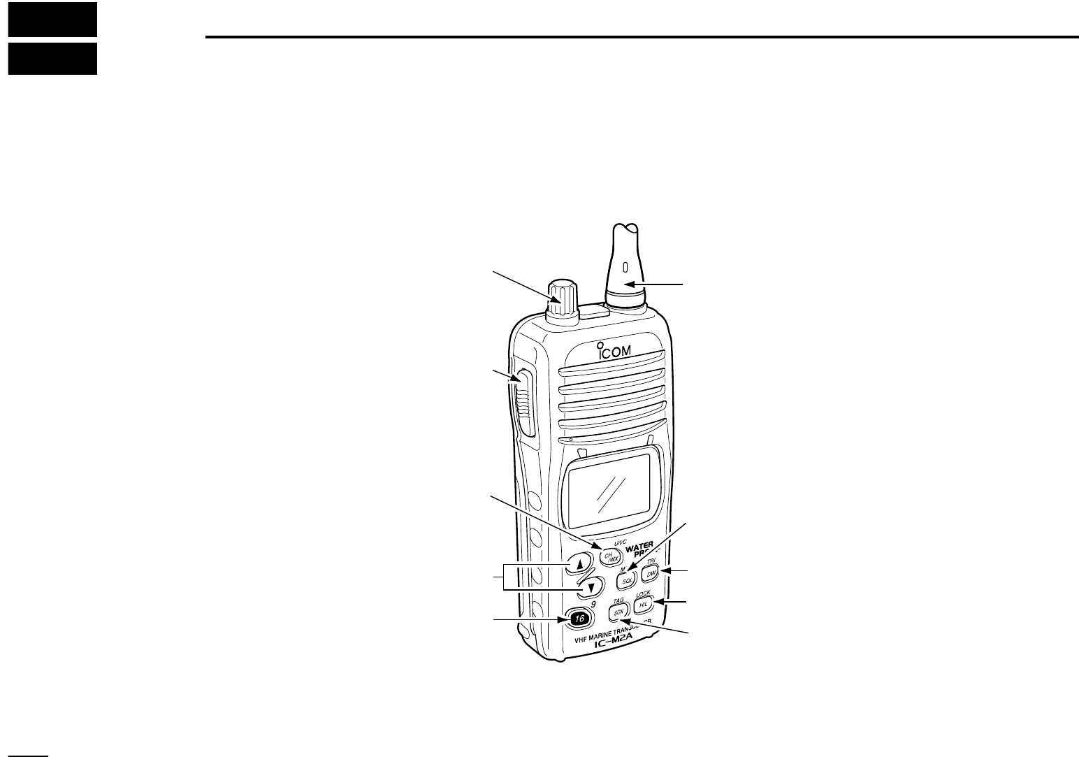
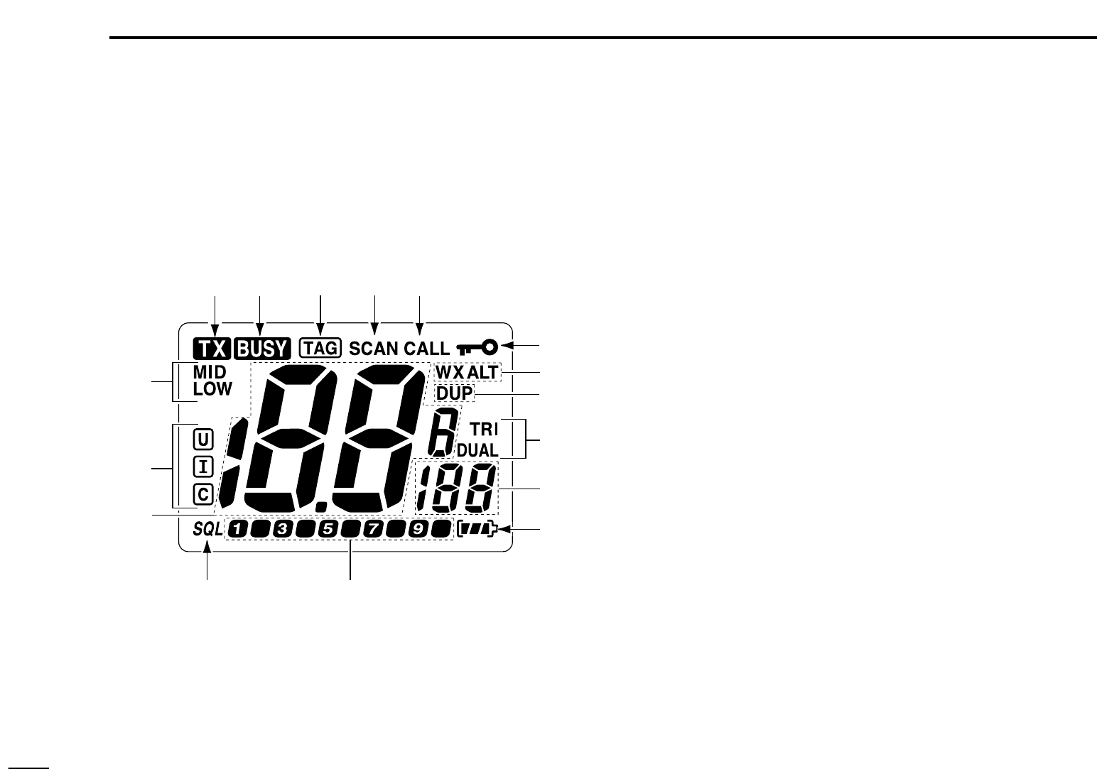
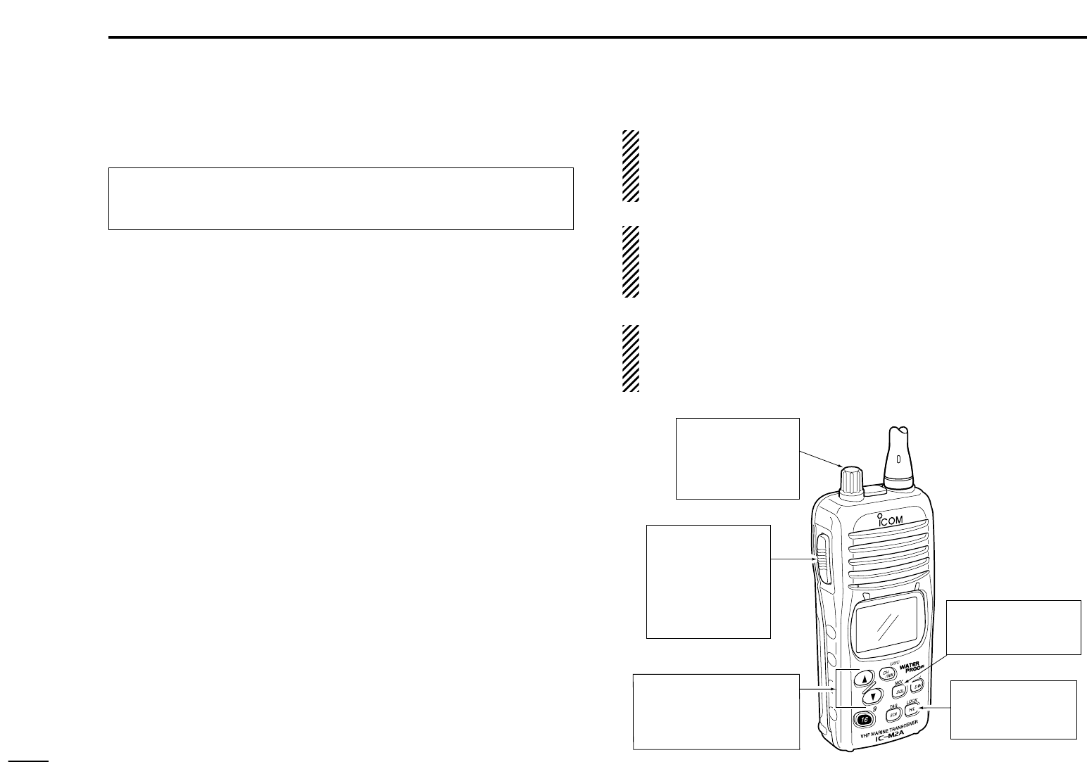
2 PANEL DESCRIPTION ............................................... 2–5
Front, top and side panels............................................ 2
Function display .......................................................... 4
3 BASIC OPERATION ................................................... 6–9
Channel selection ........................................................ 6
Lock function ............................................................... 7
Adjusting the squelch level .......................................... 7
Receiving and transmitting .......................................... 8
Call channel programming .......................................... 9
Automatic backlighting ................................................ 9
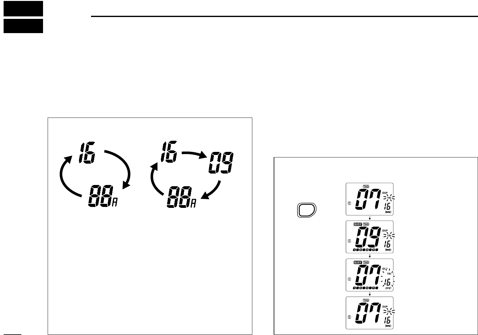
4 DUALWATCH/TRI-WATCH .......................................... 10
Description ................................................................ 10
TABLE OF CONTENTS
Operation ................................................................... 10
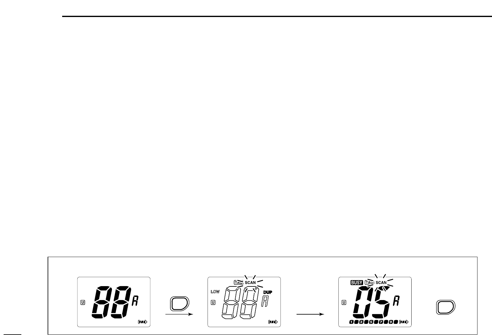
5 SCAN OPERATION ................................................ 11–12
Scan types ................................................................. 11
Setting tag channels .................................................. 12
Starting a scan .......................................................... 12
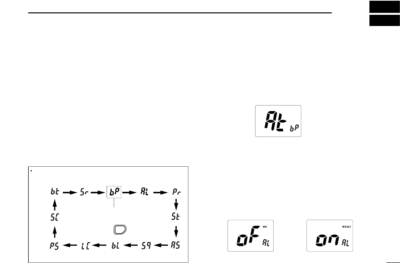
6 SET MODE ............................................................. 13–16
SET mode programming ........................................... 13
SET mode items ........................................................ 13
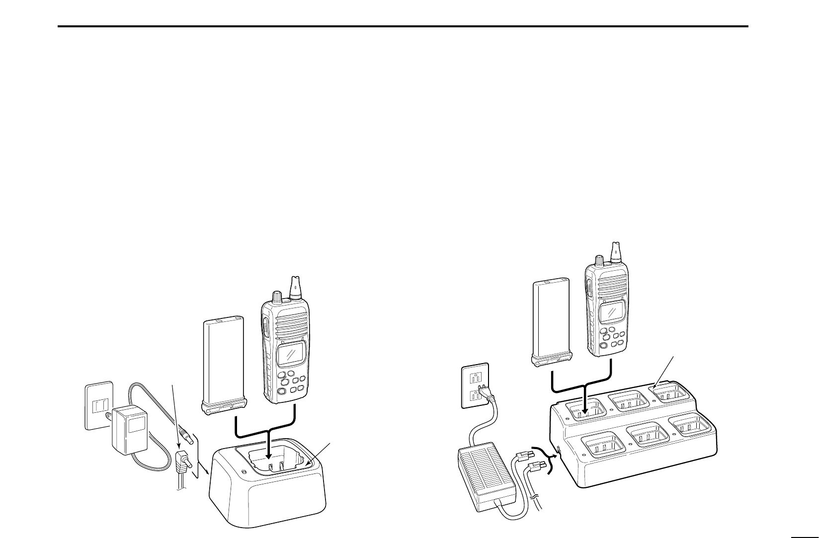
7 BATTERY CHARGING ........................................... 17–19
Battery charging ........................................................ 17
Battery cautions ......................................................... 17
Installing batteries in the battery case ....................... 18
Optional battery chargers .......................................... 19
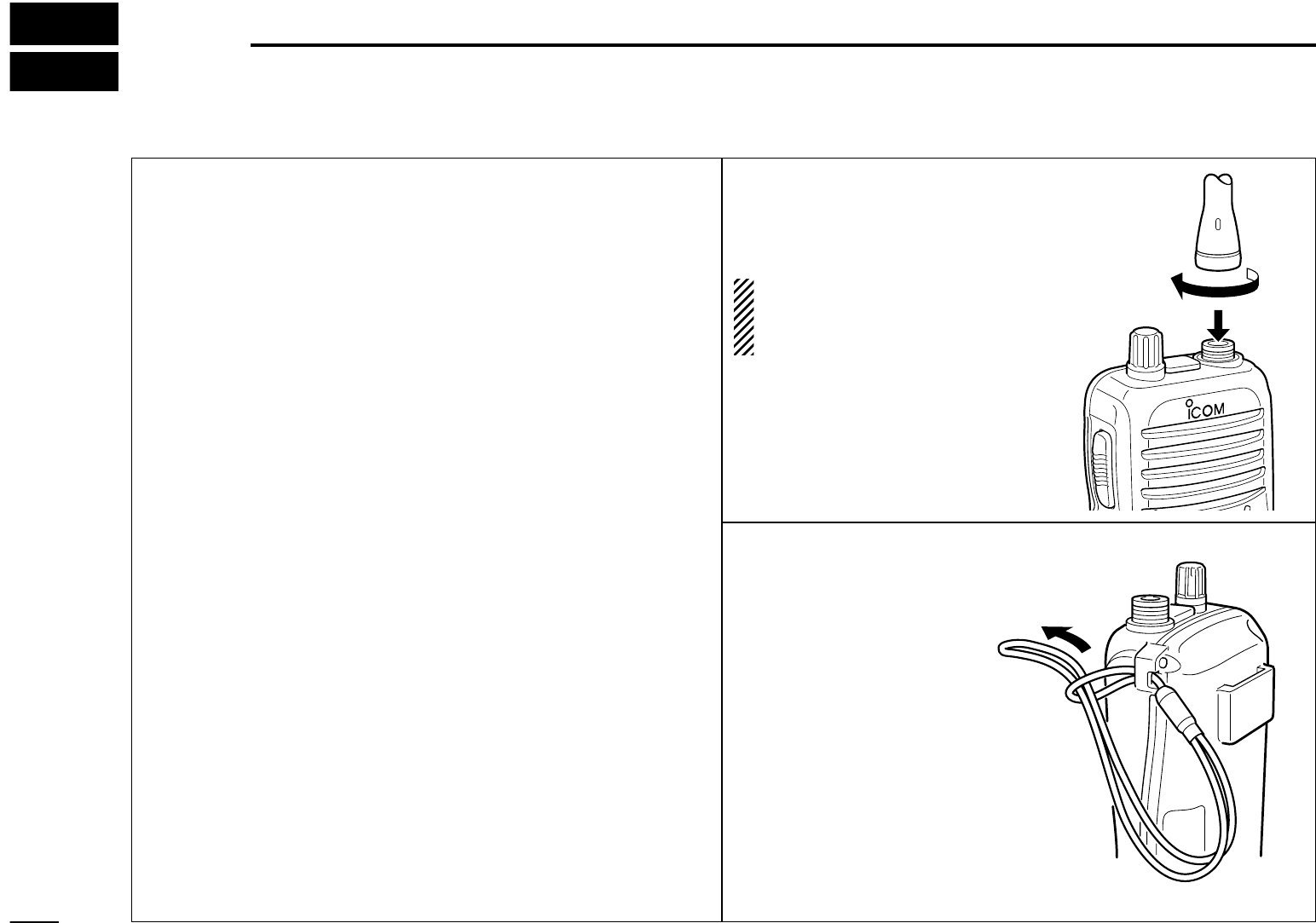
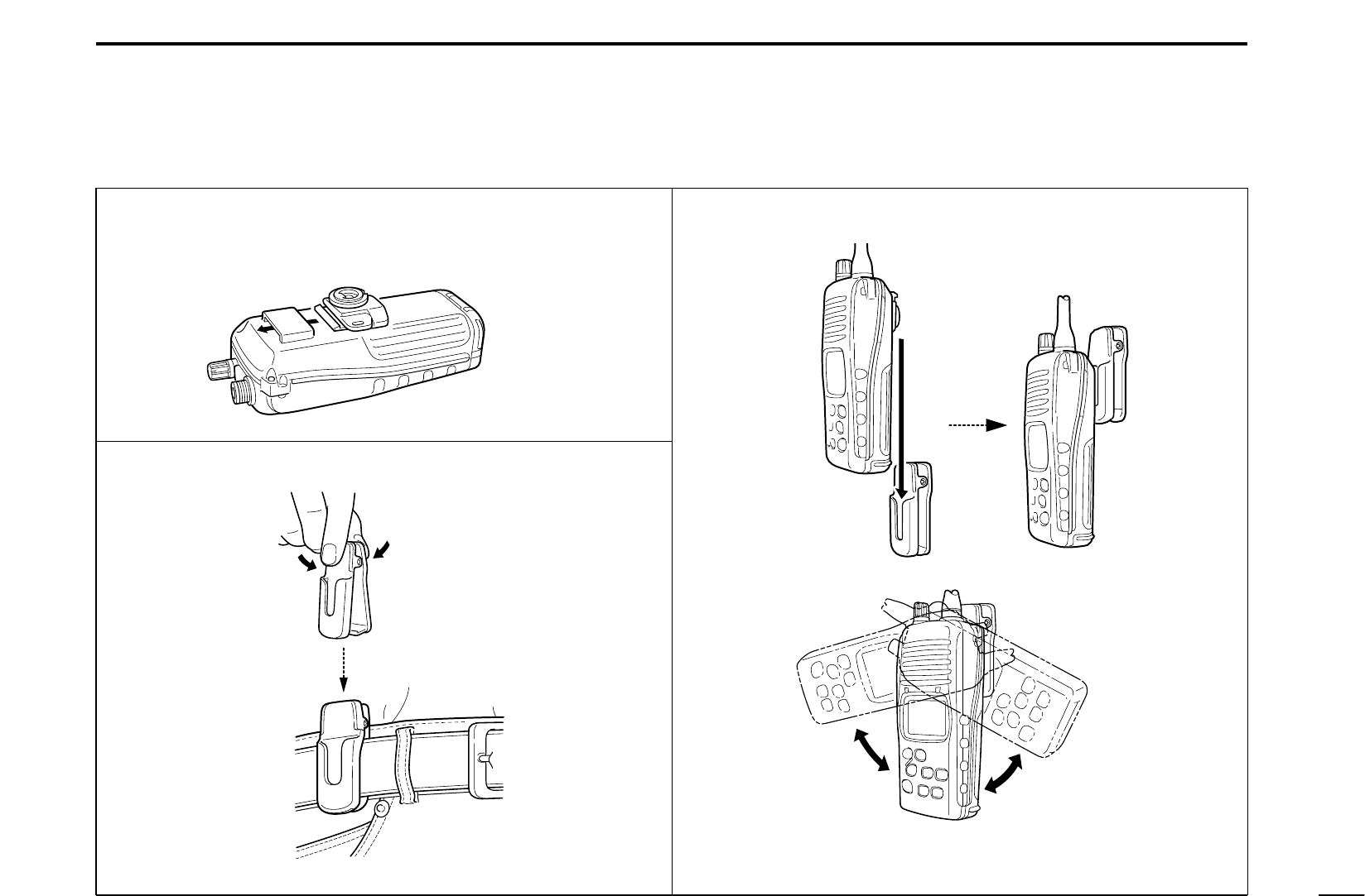
8 SUPPLIED ACCESSORIES AND ATTACHMENTS 20–22
9 TROUBLESHOOTING .................................................. 23
10 CHANNEL LIST ........................................................... 24
11 SPECIFICATIONS AND OPTIONS .............................25
Specifications ........................................................... 25
Options ..................................................................... 25
1
1
OPERATING RULES
D Priorities
Read all rules and regulations pertaining to priorities and
keep an up-to-date copy handy. Safety and distress calls
take priority over all others.
You must monitor Channel 16 when you are not operating
on another channel.
False or fraudulent distress calls are prohibited under law.
D Privacy
Information overheard but not intended for you cannot law-
fully be used in any way.
Indecent or profane language is prohibited.
D Radio licenses
(1) SHIP STATION LICENSE
When your craft is equipped with a VHF FM transceiver, you
must have a current radio station license before using the
transceiver. It is unlawful to operate a ship station which is not
licensed.
Inquire through your dealer or the appropriate government
agency for a Ship-Radiotelephone license. This license in-
cludes the call sign which is your craft’s identification for radio
purposes.
(2) OPERATOR’S LICENSE
A restricted Radiotelephone Operator Permit is the license
most often held by small vessel radio operators when a radio
is not required for safety purposes.
The Restricted Radiotelephone Operator Permit must be
posted near the transceiver or be kept with the operator. Only
a licensed radio operator may operate a transceiver.
However, non-licensed individuals may talk over a transceiver
if a licensed operator starts, supervises, ends the call and
makes the necessary log entries.
A current copy of the applicable government rules and regu-
lations is only required to be on hand for vessels in which a
radio telephone is compulsory. However, even if you are not
required to have these on hand it is your responsibility to be
thoroughly acquainted with all pertinent rules and regulations.
NOTE: Even though the IC-M2A is capable of operation
on VHF marine channels 3, 21, 23, 61, 64, 81, 82 and 83,
according to FCC regulations these simplex channels can-
not be lawfully used by the general public in USA waters.
2
2
PANEL DESCRIPTION
q CHANNEL/WEATHER CHANNEL SWITCH
[CH/WX•
U/I/C]
• Selects and toggles the regular channels and
weather channel when pushed. (pgs. 6, 7)
Selects one of 3 regular channels in se-
quence when pushed for 1 sec. (p. 6)
- International, U.S.A. and Canadian channels
are available.
w CHANNEL UP/DOWN SWITCHES [Y]/[Z]
Select an operating channel.
Selects the SET mode condition of the item.
(p. 13)
Set the squelch level in the squelch set mode.
(p. 7)
e CHANNEL 16 SWITCH [16•
9]
Selects Channel 16 when pushed. (p. 6)
Selects the call channel when pushed for
1 sec.
• Enters call Channel write mode when the call
channel is selected and this switch is pushed
for 3 sec. (p. 9)
r SCAN/TAG SWITCH [SCN•
TAG
] (p. 12)
Starts and stops normal or priority scan.
Sets and clears the displayed channel as a
tag (scanned) channel when pushed for
1 sec.
t TRANSMIT POWER/LOCK SWITCH
[H/L•
LOCK]
Selects high, middle or low power when
pushed. (p. 8)
Toggles the lock function ON/OFF when
pushed for 1 sec. (p. 7)
y DUALWATCH/TRI-WATCH SWITCH
[DW•
TRI] (p. 10)
Starts dualwatch when pushed momentarily.
Starts tri-watch when pushed for 1 sec.
• Stops dualwatch/tri-watch when either is acti-
vated.
u SQUELCH SWITCH [SQL•MONI
] (p. 7)
Push this switch, then set the squelch level
with [Y]/[Z].
• Manually opens the squelch for channel mon-
itoring when pushed for 1 sec.
i ANTENNA (p. 20)
Connects the supplied antenna.
o VOLUME CONTROL [OFF/VOL]
Turns power ON and adjusts the audio level.
!0 PTT SWITCH [PTT]
Push and hold to transmit; release to receive.
w
q
!0
o
e
r
t
y
u
i
Front, top and side panels
3
2
PANEL DESCRIPTION
CAUTION!:
When attaching or releasing a battery pack, make sure the
rubber seal is set in the groove of the battery pack/case
correctly. If the seal is not neatly in the groove it may be
damaged when attaching the battery pack/case.
If the seal is damaged, waterproofing is not guaranteed.
ï BATTERY CASE RELEASE SCREW
To remove the battery case:
Turn the screw counterclockwise, then pull the battery pack
in the direction of the arrow as shown below.
To attach the battery case:
Insert the battery case in the IC-M2A completely, then turn
the screw clockwise.
NOTE: When removing or attaching the battery case, use a
coin or at-head screwdriver to loosen or tighten the
bottom screw.
4
2
PANEL DESCRIPTION
Function display
q TRANSMIT INDICATOR (p. 8)
Appears while transmitting.
w BUSY INDICATOR (p. 8)
Appears when receiving a signal or when the squelch
opens.
e TAG CHANNEL INDICATOR (p. 12)
Appears when a tag channel is selected.
r SCAN INDICATOR (p. 12)
Blinks while scanning.
t CALL CHANNEL INDICATOR (p. 6)
Appears when the call channel is selected.
y LOCK INDICATOR (p. 7)
Appears while the lock function is activated.
u WEATHER CHANNEL/WEATHER ALERT INDICATORS
WX appears when the weather channel group is se-
lected. (p. 7)
ALT appears while the weather alert function is acti-
vated; blinks when on alert tone is received.
i DUPLEX INDICATOR
Appears when a duplex channel is selected.
q w e r
y
t
u
o
!0
!1
!2!3
!5
i
!4
!6
5
2
PANEL DESCRIPTION
o DUALWATCH/TRI-WATCH INDICATORS (p. 10)
DUAL appears during dualwatch; TRI appears during
tri-watch.
!0 SUB CHANNEL READOUT
Indicates Channel 16 during priority scan.
Indicates Channel 16 during dualwatch or tri-watch.
(p. 10)
Indicates the SET mode item while in SET mode
!1 BATTERY INDICATOR
Indicates remaining battery power.
!2 SQUELCH LEVEL INDICATOR (p. 7)
Shows squelch level when set.
This indicator can be also used as an S/RF meter when the
S/RF meter indicator setting is ON. (p. 16)
!3 SQUELCH LEVEL ADJUSTING INDICATOR (p. 7)
Appears while adjusting the squelch level.
!4 CHANNEL NUMBER READOUT
Indicates the selected operating channel number.
In SET mode, indicates the selected condition.
!5 CHANNEL GROUP INDICATOR (p. 6)
U appears when U.S.A.; I appears when International;
C appears when the Canadian channel group is se-
lected.
!6 TRANSMIT POWER INDICATOR
LOW appears when low power is selected. (p. 8)
LOW blinks when switching forced low power mode be-
cause of a high temperature error or low voltage.
MID appears when middle power is selected. (p. 8)
No indicator appears when high power is selected.
Indication
Full Middle
Charging
required
No
battery
Battery level
D U.S.A., International and Canadian channels
There are 57 U.S.A., 57 International and 61 Canadian chan-
nels. These channel groups may be specied for the operat-
ing area.
q Push [CH/WX] to select a regular channel.
- If a weather channel appears, push [CH/WX] again.
w Push [Y]/[Z] switches to select a channel.
- DUP appears for duplex channels.
e To change the channel group, push [CH/WX
U/I/C] for
1 sec.
- U.S.A.,International and Canadian channels can be selected in
sequence.
Push for 1 sec.
U.S.A. channels
Canadian channels
International channels
CH
/WX
U/I/C
CH
/WX
U/I/C
CH
/WX
U/I/C
6
3
BASIC OPERATION
Channel selection
D Channel 16
Channel 16 is the distress channel. It is used for establishing
initial contact with another station and for emergency
communications. Channel 16 is monitored during dualwatch
or tri-watch. While standing by you are required to monitor
Channel 16.
D
Channel 9 (Call channel)
Channel 9 is the leisure-use call channel. Each regular
channel group has a separate call channel. The call channel
is monitored during tri-watch. The call channels can be
programmed (p. 9) and are used to store your most often-
used channels in each channel group for quick recall.
Push [169] for 1 sec. to select the call channel for the
selected channel group.
- CALL and call channel number
appear.
-
Each channel group can have its
own call channel when programmed.
16
9
Push
7
3
BASIC OPERATION
D Weather channels
There are 10 weather channels. These are used for monitor-
ing weather channels from the NOAA (National Oceano-
graphic and Atmospheric Administration) broadcasts.
The IC-M2A can detect a weather alert tone on the selected
weather channel while scanning. See the SET mode items
on p. 13.
q Push [CH/WX] to select a weather channel group.
w Push [Y]/[Z] to select a weather channel.
e Push [CH/WX] to return to the condition before selecting
weather channel group.
Lock function
This function electronically locks all keys, except [PTT],
[SQL
MONI] and [H/LLOCK] to prevent accidental channel
changes and function access.
Push [H/LLOCK] for 1 sec. to turn the lock function ON and
OFF.
- Only [PTT], [H/L
LOCK] and [SQL
MONI] are functional.
Appears while the
lock function is used.
Push
CH
/WX
U/I/C
Adjusting the squelch level
The IC-M2A has a squelch even though there is no control
knob for it. In order to receive signals properly, as well as for
scan to function, the squelch must be adjusted to a suitable
level.
q Push [SQL
MONI
], then adjust the squelch level with [Y]/[Z].
- SQL indicator and squelch level indicator appear.
- There are 11 squelch levels to choose from: 0 is completely
open; 10 is the maximum squelch level.
- When no keys are pushed for 5 sec., the transceiver returns to
normal condition.
w Push [SQL
MONI] again to return to normal condition.
(Level 10: Max. squelch level)
Each dot indicates the squelch level
Appears durling squelch
level adjustment.
8
q Rotate [OFF/VOL] clockwise to turn power ON.
- Use the squelch function to mute any audio noise if necessary.
Refer to the previous page for details.
w Push* [SQLMONI] for 1 sec., and rotate volume to set
audio output level.
*According to Monitor action selection in SET mode (p. 14).
e Push [Y]/[Z] to select the desired channel.
- When receiving a signal, BUSY appears and audio is emitted
from the speaker.
(The S/RF meter appears while S/RF meter turned ON in SET
mode.)
- Further adjustment of [OFF/VOL] may be necessary at this point.
r Push [H/L] to select the output power if necessary.
- LOW appears when low power is selected; MID appears when
middle power is selected; no indicator appears when high power
is selected.
- Choose low power to conserve battery power, choose high power
for longer distance communications.
- Some channels are for low power only.
t Push and hold [PTT] to transmit, then speak into the
microphone.
- TX
appears.
(The S/RF meter appears while S/RF meter is turned ON in SET
mode.)
- Channel 70 cannot be used for transmission (for GMDSS use).
y Release [PTT] to receive.
Receiving and transmitting
CAUTION: Transmitting without an antenna may
damage the transceiver.
IMPORTANT: To maximize the readability of your trans-
mitted signal, pause a few sec. after pushing [PTT], hold
the microphone 5 to 10 cm (2 to 4 inches) from your
mouth and speak at a normal voice level.
NOTE: The transceiver has a power save function to con-
serve the battery power and cannot be turned OFF. The
power save function activates automatically when no sig-
nal is received for 5 sec.
For U.S.A version: To prevent accidental prolonged
transmission, etc., the IC-M2A has a time-out timer func-
tion. This timer cuts a transmission OFF after 5 min. of
continuous transmission.
w Set squelch
level
w Set squelch level
e Set channel
r Set output
power
t Push to
transmit
y Release to
receive
q Power ON
w Set volume
3
BASIC OPERATION
9
3
BASIC OPERATION
Call channel programming
The call channel switch is used to select Channel 9 by de-
fault, however, you can program your most often-used chan-
nels in each channel group for quick recall.
q Push [CH/WX
U/I/C] for 1 sec. to
select the desired channel
group (USA, INT, CAN) to be
programmed.
w Push [16
9] for 1 sec. to select
the call channel of the selected
channel group.
- CALL and call channel number
appear.
e Push [169] again for 3 sec.
(until long beep changes to 2
short beeps) to enter call chan-
nel programming condition.
- Call channel number and channel
group to be programmed ash.
r Push [Y]/[Z] to select the de-
sired channel.
t Push [16
9] to program the dis-
played channel as the call chan-
nel.
- The call channel number and chan-
nel group stop ashing.
Automatic backlighting
This function is convenient for nighttime operation. The auto-
matic backlighting can be deactivated in SET mode. (p. 15)
Push any key except for [PTT] to turn the backlighting ON.
- The backlighting is automatically turned OFF after 5 sec. of in-
activity.
10
4
DUALWATCH/TRI-WATCH
Description
Dualwatch monitors Channel 16 while you are receiving an-
other channel; tri-watch monitors Channel 16 and the call
channel while receiving another channel.
DUALWATCH/TRI-WATCH SIMULATION
If a signal is received on Channel 16, dualwatch/tri-watch pauses
on Channel 16 until the signal disappears.
If a signal is received on the call channel during tri-watch, tri-
watch becomes dualwatch until the signal disappears.
To transmit on the selected channel during dualwatch/tri-watch,
push and hold [PTT].
Call channel
Dualwatch Tri-watch
Operation
q Select the desired operating channel.
w Push [DW
TRI] momentarily to start dualwatch; push
[DW
TRI] for 1 sec. to start tri-watch.
- DUAL ashes during dualwatch; TRI ashes during tri-watch.
- Beep tones sound when a signal is received on Channel 16.
- Tri-watch becomes dualwatch when receiving a signal on the call
channel.
e To cancel dualwatch/tri-watch, push [DWTRI] again.
[Example]: Operating tri-watch on INT Channel 07.
Tri-watch starts.
Push for 1 sec.
Signal is received
on call channel.
Signal received on
Channel 16 takes
priority.
Tri-watch resumes
after the signal
disappears.
DW
TRI
11
5
SCAN OPERATION
Scan types
Scanning is an efcient way to locate signals quickly over a
wide frequency range. The transceiver has a priority scan and
a normal scan.
In addition, weather alert functions are available for standby
convenience. (p. 13)
Set the tag channels (channels to be scanned) before scan-
ning. Clear the tag channels which inconveniently stop scan-
ning, such as those used for digital communications.
NOTE: Choose priority or normal scan in SET mode. (p. 14)
PRIORITY SCAN
Priority scan searches through all tag channels in se-
quence while monitoring Channel 16. When a signal is de-
tected on Channel 16, scan pauses until the signal
disappears; when a signal is detected on a channel other
than Channel 16, scan becomes dualwatch until the signal
disappears.
WX*
CH 01
CH 16
CH 02
CH 05 CH 04
CH 03
* Previously selected weather channel
when weather alert function is ON.
NORMAL SCAN
Normal scan, like priority scan, searches through all tag
channels in sequence. However, unlike priority scan, Chan-
nel 16 is not checked unless Channel 16 is set as a tag
channel.
CH 01 CH 02
WX*
CH 05 CH 04
CH 03
* Previously selected weather channel
when weather alert function is ON.
12
5
SCAN OPERATION
Setting tag channels
For more efficient scanning, add desired channels as tag
channels or clear tag channels for unwanted channels. Chan-
nels set as non-tag channels will be skipped during scanning.
Tag channels can be assigned to each channel group (USA,
INT, CAN) independently.
q Select the desired channel group (USA, INT, CAN) by
pushing [CH/WX
U/I/C] for 1 sec., if desired.
w Select the desired channel to set as a tag channel.
e Push [SCN
TAG] for 1 sec. to set the displayed channel as
a tag channel.
- TAG appears in the function display.
r To cancel the tag channel setting, push [SCNTAG] for 1
sec.
- TAG disappears.
Clearing all tag channels in the selected channel group
While pushing [SCN
TAG], turn the power ON to clear all
tag channels in the channel group.
Starting a scan
Set scan type, weather alert function and scan resume timer
in advance using SET mode. (pgs. 13, 14)
q Select the desired channel group (USA, INT, CAN) by
pushing [CH/WX
U/I/C] for 1 sec., if desired.
- When the weather alert function is in use, select the desired
weather channel with [CH/WX] and the [Y]/[Z].
w Push [SCN
TAG] to start priority or normal scan.
- SCAN blinks in the function display.
- 16 appears during priority scan.
- When a signal is detected, scan pauses until the signal disap-
pears or resumes after pausing 5 sec. according to SET mode
setting. (Channel 16 is still monitored during priority scan.)
- Push [Y]/[Z] to check tag channels, to change the scanning di-
rection or resume the scan manually.
e To stop the scan, push [SCN
TAG].
- SCAN disappears.
- Pushing [PTT], [169], [CH/WX] or [DWTRI] also stops the scan.
[Example]: Starting a normal scan.
13
6
SET MODE
Weather alert function OFF (default) Weather alert function ON
SET mode programming
SET mode is used to change the conditions of 12 transceiver
functions: beep tone, weather alert, scan type, scan resume
timer, auto scan, monitor switch, automatic backlighting, LCD
contrast, auto power save, self check, battery voltage and
S/RF meter functions.
q Turn power OFF.
w While pushing [SQL
MONI], turn power ON and continue
pushing [SQL
MONI] until bP appears.
e Release [SQL
MONI].
r Push
[Y]/[Z] to select the desired condition of the item.
t Push [SQL
MONI] to select the desired item, if necessary.
y To exit SET mode, turn the power OFF, then ON again, or
push [16
9].
SET MODE CONSTRUCTION
Weather
alert
S/RF
meter
Scan resume
timer
Auto
scan
Automatic
backlighting
Monitor
switch
LCD
contrast
Self
check
Battery
voltage
Auto
power save
Scan
type
Beep tone
Starting item
Push
SQL
MONI
SET mode items
D Beep tone bP
You can select silent operation by turning beep tones OFF or
you can have confirmation beeps sound at the push of a
switch by turning beep tones ON.
AUTO (At): Beep tone is linked with volume tone.
110: Beep tone scale is set from 110 scale (Max. is 10).
D Weather alert function AL
NOAA broadcast stations transmit weather alert tones before
important weather announcements. When the weather alert
function is turned ON, the transceiver detects the alert, the
ALT indicator blinks and sounds a beep tone until the trans-
ceiver is operated. The previously selected (used) weather
channel is checked periodically during standby or while scan-
ning.
ALT appears when the function is set ON.
Beep tone AUTO (default)
D Priority scan function Pr
The transceiver has 2 scan types. Normal scan and priority
scan. Normal scan searches all tag channels in the selected
channel group. Priority scan searches all tag channels in se-
quence while monitoring Channel 16.
D Scan resume timer St
The scan resume timer can be selected as a pause (OFF) or
timer scan (ON). When OFF is selected, the scan pauses
until a received signal disappears. When ON is selected, the
scan pauses for 5 sec. after receiving a signal and then re-
sumes even if the signal is still being received.
14
6
SET MODE
D Auto scan function
AS
While in standby, this function automatically starts the desired
scan (normal or priority scan) 30 sec. after operation.
Scan indicator blinks while scanning.
D Monitor action selection Sq
The monitor function cuts off the squelch function temporarily.
This selection contains PUSH or HOLD settings as shown
below.
PUSH (Pu): After pushing the [SQL
MONI] for 1 sec., the
squelch function is cut off until [SQL
MONI] is
released. (default)
HOLD (Ho): After pushing the [SQL
MONI] for 1 sec., the
squelch function is cut off continuously until
another key is pushed.
Normal scan (default)
Auto scan OFF (default)
Monitor switch PUSH (default)
Scan timer OFF (default)
15
6
SET MODE
D Automatic backlighting
bL
This function is convenient for nighttime operation. The auto-
matic backlighting turns the backlighting ON when pushing
any key except for [PTT].
The backlighting is automatically turned OFF after 5 sec. of inactivity.
D LCD contrast selection LC
The contrast of the LCD can be adjusted from 4 levels.
1 (low contrast) 4 (high contrast); 3 (default)
D Auto power save function PS
The power save function reduces current drain by deactivat-
ing the receiver circuit for preset intervals.
D Self check function SC
The self check function checks transceiver conditions by it-
self, and informs you in case a problem is found. The follow-
ing items are checked after the power is turned ON, then it
switches to operation mode.
Temperature (Outside of 20°C to +60°C; 4°F to +140°F)
Connected battery voltage
Water intrusion
When error messages as shown
below are displayed, see trouble
shooting for advice (p. 23).
Automatic backlighting ON (default)
LCD contrast (default)
Auto power save ON (default)
Self check OFF (default)
Error messages
Temperature error Battery voltage error Water intrusion error
16
6
SET MODE
D Battery voltage indicator
bt
This function contains display or non-display settings of the
voltage of the connected battery pack when the power is ON.
The voltage of the connected battery pack is displayed for 2 sec.
after power is turned ON.
D S-meter/RF meter indicator Sr
This function contains display or non-display setting of the
S-meter/RF meter.
Battery voltage OFF (default)
S-meter/RF meter OFF (default)
Indication Switch
Beep tone
Function
Weather alert function
Scan type selection
Scan resume timer
Auto scan function
Monitor switch selection
Automatic backlighting
LCD contrast selection
Auto power save function
Self check function
Battery voltage indicator
S-meter/RF meter indicator
OFF / Auto* / 1 10
OFF* / ON
OFF* / ON
OFF* / ON
OFF* / ON
Push* / Hold
ON* / OFF
3* / 1 4
ON* / OFF
OFF* / ON
OFF* / ON
OFF* / ON
"bP"
"AL"
"Pr"
"St"
"AS"
"Sq"
"bL"
"LC"
"PS"
"SC"
"bt"
"Sr"
*default setting
SET MODE LIST
17
7
BATTERY CHARGING
Battery charging
Prior to using the transceiver for the rst time, the Ni-Cd bat-
teries must be fully charged for optimum life and operation.
Recommended temperature range for charging:
+50°F to +104°F (+10°C to +40°C)
Use the supplied AC adapter (BC-147A/E or BM-95V) only.
NEVER use other adapters.
NEVER connect DC power to the battery case when in-
stalling alkaline batteries. Such a connection will damage
the transceiver.
CAUTION: To avoid damage to the transceiver, turn it OFF
while charging.
Battery cautions
NEVER incinerate used Ni-Cd batteries. Internal battery gas
may cause an explosion.
NEVER immerse batteries in water. If the battery case be-
comes wet, be sure to wipe it dry BEFORE attaching it to the
transceiver.
NEVER short terminals of the battery case. Also, current may
ow into nearby metal objects so be careful when placing bat-
tery cases in handbags, etc.
If your Ni-Cd batteries seem to have no capacity even after
being charged, completely discharge them by leaving the
power ON overnight. Then, fully charge the Ni-Cd batteries
again. If the batteries still do not retain a charge (or very little),
new batteries must be purchased.
D Recycling information (U.S.A. only)
The product that you have purchased contains a
rechargeable battery. The battery is recyclable. At
the end of its life, under various state and local
laws, it may be illegal to dispose of this battery
into the municipal waste stream. Call 1-800-822-8837 for bat-
tery recycling options in your area or contact your dealer.
18
7
BATTERY CHARGING
Installing batteries in the
battery case (Not supplied with some versions)
When using a battery case attached to the transceiver, install
6 × AA(R6) size alkaline batteries as illustrated below.
q Remove the battery case from the transceiver.
w Install 6 × AA(R6) size alkaline batteries.
Be sure to observe the correct polarity.
CAUTION:
When installing batteries, make sure they are all the
same brand, type and capacity. Also, do not mix new and
old batteries together.
Keep battery contacts clean. Its a good idea to clean bat-
tery terminals once a week.
ï Charging connections
q Attach the BC-150 to a at surface, such as desk or cabin, etc., if
desired.
w Connect the AC adapter (BC-147A/E or BM-95V) as shown below.
e Insert the battery pack with/without the transceiver into the
charger.
The charge indicator lights green.
r Charge the battery pack approx. 8 hours, depending on the re-
maining power condition.
CAUTION: DO NOT charge BP-224 more than 12 hours.
Otherwise, BP-224 will be damaged. BP-224 must
be charged for 812 hours only.
AC adapter
(BC-147A/E
or BM-95V)
BC-150
BP-224
IC-M2A
Supplied screws
Charge indicator
Lights green when
BP-224 (with/without
IC-M2A) is inserted.
19
7
BATTERY CHARGING
D Rapid charging with the BC-121N+AD-103
The optional BC-121N allows up to 6 battery packs to be
charged simultaneously. The following are additionally re-
quired.
Six AD-103.
An AC adapter (BC-124) or the DC power cable (OPC-656).
AC adapter
(purchased
separately)
AD-103 charger
adapters are installed
in each slot.
BP-224
IC-M2A
DC power cable
(Connect with the DC power supply;
13.8 V/at least 7 A)
Optional battery chargers
D Rapid charging with the BC-119N+AD-103
The optional BC-119N provides rapid charging of battery
packs. The following are additionally required.
AD-103
An AC adapter (may be supplied with BC-119N depending
on version).
AC adapter
(Not supplied with some
versions.)
OPC-515L or
CP-17L
AD-103 charger
adapter is installed
in BC-119N.
BP-224
IC-M2A
20
8
SUPPLIED ACCESSORIES AND ATTACHMENTS
D Supplied accessories
The following accessories are supplied: Qty.
q Flexible antenna . . . . . . . . . . . . . . . . . . . . . . . . . . . . . . . .1
w Swivel belt clip . . . . . . . . . . . . . . . . . . . . . . . . . . . . . . . . .1
e Handstrap . . . . . . . . . . . . . . . . . . . . . . . . . . . . . . . . . . . . .1
r Battery case (BP-223)*
1
. . . . . . . . . . . . . . . . . . . . . . . . . .1
t Ni-Cd battery pack (BP-224) . . . . . . . . . . . . . . . . . . . . . . .1
y AC adapter (BC-147A/E or BM-95V)*
2
. . . . . . . . . . . . . . .1
u Battery charger (BC-150) . . . . . . . . . . . . . . . . . . . . . . . . .1
i Screws for the BC-150 (M3.5 × 20) . . . . . . . . . . . . . . . . .2
*
1
Not supplied with some versions.
*
2
Depending on version.
D Flexible antenna
Connect the supplied exible
antenna to the antenna con-
nector.
CAUTION: Transmitting
without an antenna may
damage the transceiver.
D
Handstrap
Slide the handstrap
through the loop on the
side of the transceiver as
illustrated at right. Facili-
tates carrying.
e Insert the stopper to the back of the belt clip.
Once the transceiver is locked in place, it will swivel 360 de-
grees.
21
8
SUPPLIED ACCESSORIES AND ATTACHMENTS
D Swivel belt clip
To attach:
q Slide the stopper into the plastic loop on the back of the
transceiver.
w Clip the belt clip to a part of your belt.
22
8
SUPPLIED ACCESSORIES AND ATTACHMENTS
To remove:
q Turn the transceiver upside down, and then lift to release
the transceiver from the belt clip.
w Release the belt clip.
e Push the top of the stopper towards the transceiver and out
at the same time, then push it downwards and free of the
plastic loop.
RR
CAUTION!
HOLD THE TRANSCEIVER TIGHTLY, WHEN ATTACH-
ING OR REMOVING THE TRANSCEIVER FROM THE
BELT CLIP.
If the transceiver is accidentally dropped and the swivel
belt clips stopper is scratched or damaged, the swivel
belt clip may not work properly.
23
9
TROUBLESHOOTING
PROBLEM POSSIBLE CAUSE SOLUTION. REF.
No sound comes from
the speaker.
Squelch level is too deep.
Volume level is too low.
Speaker has been exposed to water.
p. 7
p. 8
Set squelch to the threshold point.
Set [OFF/VOL] to a suitable level.
Drain water from the speaker.
No power comes ON.
The battery is exhausted.
Bad connection to the battery pack.
p. 17
p. 3
Recharge the battery pack.
Check the connection to the transceiver.
Transmitting is impossi-
ble, or high power can
not be selected.
Some channels are for low power or re-
ceive only.
The battery is exhausted.
The output power is set to low.
pgs. 2, 4
p. 17
p. 2
Change channels.
Recharge the battery pack.
Push [H/L] to select high power.
The display channel
cannot be changed.
Lock function is activated. Push [H/L
LOCK] for 1 sec. to cancel the
function.
p. 2
Scan does not start.
•“TAG channels are not programmed. Set the desired channels as TAG channels. p. 12
No beeps sound.
Beep tones are turned OFF.
Set the beep tones to AUTO or 110 in SET
mode.
p. 13
Self check error.
(Temperature error)
Transceivers inside temperature is below
20°C (4°F) or above +60°C (+120°F).
Leave the transceiver at room temperature
for a while. Turn the power ON to check if the
internal temperature has returned to normal.
Self check error.
(Battery voltage error)
The connected battery packs voltage is
more than 11 V.
Verify the battery voltage is correct.
Self check error.
(Water intrusion error)
Water has entered the transceiver.
Have the transceiver checked at your local
distributor or dealer to see whether the trans-
ceiver works properly or not.
24
CHANNEL LIST
10
Channel number
USA CAN
Transmit
Receive
Frequency (MHz)
INT
Channel number Frequency (MHz)
USA CAN
Transmit
ReceiveINT
Channel number Frequency (MHz)
USA CAN
Transmit
ReceiveINT
Channel number Frequency (MHz)
USA CAN
Transmit
ReceiveINT
WX channel
Frequency (MHz)
Transmit Receive
01 156.050 160.650
01A 156.050 156.050
02 156.100 160.700
03 156.150 160.750
03A 156.150 156.150
156.200 160.800
04A 156.200 156.200
156.250 160.850
05A 05A 156.250 156.250
06 06 156.300 156.300
156.350 160.950
07A 07A 156.350 156.350
08 08 156.400 156.400
09 09 156.450 156.450
10 10 156.500 156.500
11 11 156.550 156.550
12 12 156.600 156.600
13
*
13
*
156.650 156.650
14 14 156.700 156.700
15
*
15
*
156.750 156.750
16 16 156.800 156.800
17
*
17
*
156.850 156.850
156.900 161.500
18A 18A 156.900 156.900
01
02
03
04
05
06
07
08
09
10
11
12
13
14
15
*
16
17
18
156.950 161.550
19A 19A 156.950 156.950
20
20
*
157.000 161.600
21 157.050 161.650
21A 21A 157.050 157.050
157.100 161.700
22A 22A 157.100 157.100
23 157.150 161.750
23A 157.150 157.150
24 24 157.200 161.800
25 25 157.250 161.850
26 26 157.300 161.900
27 27 157.350 161.950
28 28 157.400 162.000
60 156.025 160.625
156.075 160.675
61A 61A 156.075 156.075
156.125 160.725
62A 156.125 156.125
156.175 160.775
63A 156.175 156.175
64 156.225 160.825
64A 64A 156.225 156.225
19
20
21
22
23
24
25
26
27
28
60
61
62
63
64
20A 157.000 157.000
66A
66A
*
156.325 160.925
67
*
67 156.375 156.375
68 68 156.425 156.425
69 69 156.475 156.475
70 70
156.525
71 71 156.575 156.575
72 72 156.625 156.625
73 73 156.675 156.675
74 74 156.725 156.725
77
*
77
*
156.875 156.875
156.925 161.525
78A 78A 156.925 156.925
156.975 161.575
79A 79A 156.975 156.975
157.025 161.625
80A 80A 157.025 157.025
157.075 161.675
81A 81A 157.075 157.075
157.125 161.725
82A 82A 157.125 157.125
66
67
68
69
70
71
72
73
74
77
78
79
80
81
82
156.325 156.32566A
85 85 157.275 161.875
85A 157.275 157.275
86 86 157.325 161.925
86A 157.325 157.325
87 87 157.375 161.975
87A 157.375 157.375
88 88 157.425 162.025
88A 157.425 157.425
85
86
87
88
21b Rx only
Rx only
161.650
25b Rx only 161.850
28b Rx only 162.000
83b Rx only 161.775
4
1 RX only 162.550
2 RX only 162.400
3 RX only 162.475
5 RX only 162.450
6 RX only 162.500
7 RX only 162.525
8 RX only 161.650
9 RX only 161.775
10 RX only 163.275
RX only 162.425
156.275 160.875
65A 65A 156.275 156.275
65
65A
84A
83 157.175 161.775
83A 83A 157.175 157.175
84 84 157.225 161.825
83
84
157.225 157.225
*Low power only.
NOTE: Simplex channels 3, 21, 23, 61, 64, 81, 82 and 83 CANNOT
be lawfully used by the general public in USA waters.
Count on us!
1-1-32 Kamiminami, Hirano-ku, Osaka 547-0003 Japan
A-6113H-1EX-q
Printed in Japan
© 2001, 2002 Icom Inc.
30

Hulp nodig? Stel uw vraag in het forum

Spelregels

Misbruik melden

Gebruikershandleiding.com neemt misbruik van zijn services uitermate serieus. U kunt hieronder aangeven waarom deze vraag ongepast is. Wij controleren de vraag en zonodig wordt deze verwijderd.

Product:

Bijvoorbeeld antisemitische inhoud, racistische inhoud, of materiaal dat gewelddadige fysieke handelingen tot gevolg kan hebben.

Bijvoorbeeld een creditcardnummer, een persoonlijk identificatienummer, of een geheim adres. E-mailadressen en volledige namen worden niet als privégegevens beschouwd.

Spelregels forum

Om tot zinvolle vragen te komen hanteren wij de volgende spelregels:

Belangrijk! Als er een antwoord wordt gegeven op uw vraag, dan is het voor de gever van het antwoord nuttig om te weten als u er wel (of niet) mee geholpen bent! Wij vragen u dus ook te reageren op een antwoord.

Belangrijk! Antwoorden worden ook per e-mail naar abonnees gestuurd. Laat uw emailadres achter op deze site, zodat u op de hoogte blijft. U krijgt dan ook andere vragen en antwoorden te zien.

Abonneren

Abonneer u voor het ontvangen van emails voor uw Icom IC-M2A bij:


U ontvangt een email met instructies om u voor één of beide opties in te schrijven.


Ontvang uw handleiding per email

Vul uw emailadres in en ontvang de handleiding van Icom IC-M2A in de taal/talen: Engels als bijlage per email.

De handleiding is 0,64 mb groot.


U ontvangt de handleiding per email binnen enkele minuten. Als u geen email heeft ontvangen, dan heeft u waarschijnlijk een verkeerd emailadres ingevuld of is uw mailbox te vol. Daarnaast kan het zijn dat uw internetprovider een maximum heeft aan de grootte per email. Omdat hier een handleiding wordt meegestuurd, kan het voorkomen dat de email groter is dan toegestaan bij uw provider.

Stel vragen via chat aan uw handleiding

Stel uw vraag over deze PDF

Uw handleiding is per email verstuurd. Controleer uw email

Als u niet binnen een kwartier uw email met handleiding ontvangen heeft, kan het zijn dat u een verkeerd emailadres heeft ingevuld of dat uw emailprovider een maximum grootte per email heeft ingesteld die kleiner is dan de grootte van de handleiding.

Er is een email naar u verstuurd om uw inschrijving definitief te maken.

Controleer uw email en volg de aanwijzingen op om uw inschrijving definitief te maken

U heeft geen emailadres opgegeven

Als u de handleiding per email wilt ontvangen, vul dan een geldig emailadres in.

Uw vraag is op deze pagina toegevoegd

Wilt u een email ontvangen bij een antwoord en/of nieuwe vragen? Vul dan hier uw emailadres in.


Info