i
FOREWORD
Thank you for purchasing this Icom product. The IC-
F7000
HF TRANSCEIVER
is designed and built with
Icom’s superior technology and craftsmanship. With
proper care, this product should provide you with years
of trouble-free operation.
We want to take a couple of moments of your time to
thank you for making the IC-F7000 your radio of
choice, and hope you agree with Icom’s philosophy of
“technology first.” Many hours of research and devel-
opment went into the design of your IC-F7000.
D
FEATURES
❍ ALE (Automatic Link Establishment)/Selcall
capability
❍ Digital Signal Processor (DSP) allows flex-
ible filter selection
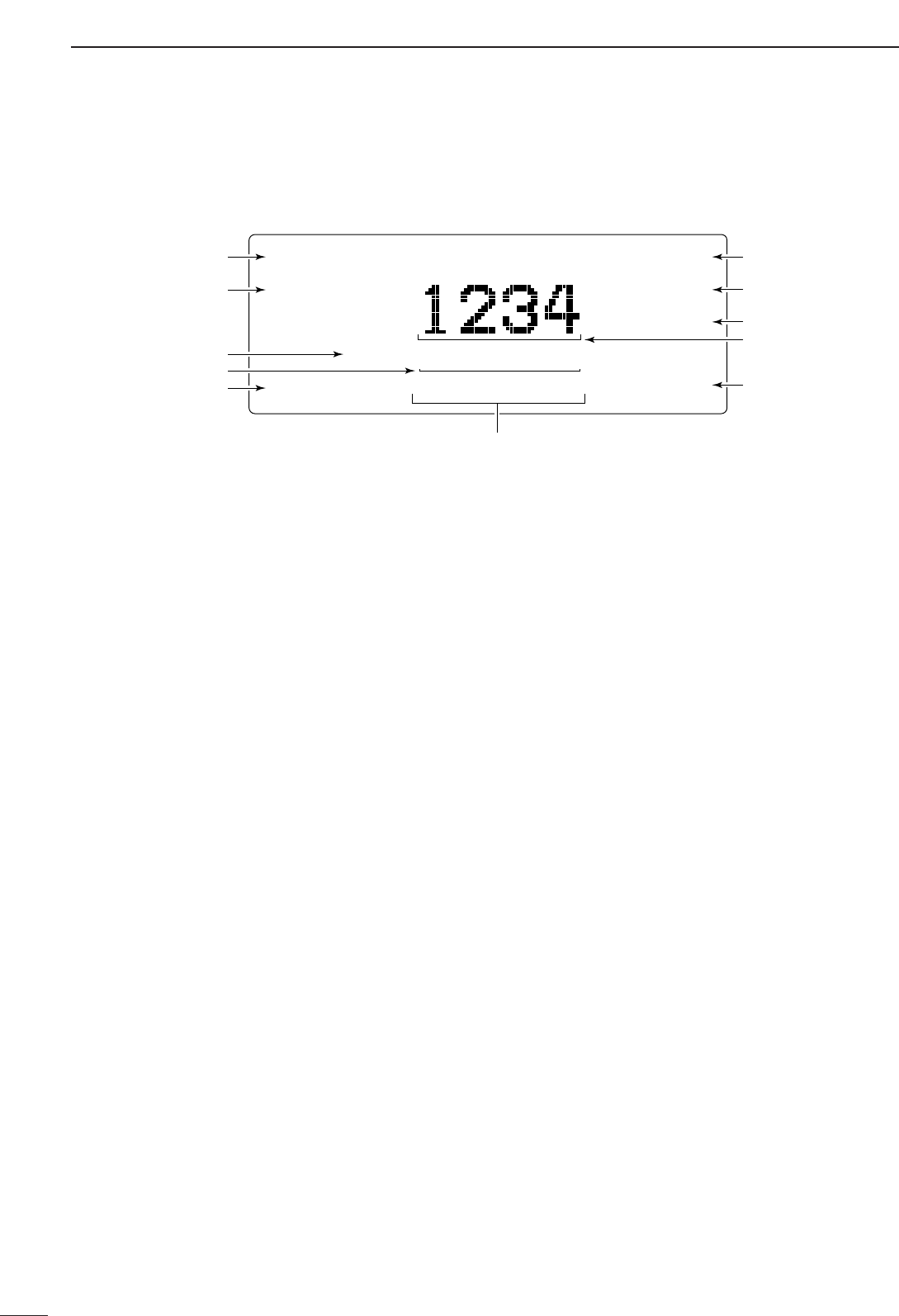
❍ Full-dot matrix LCD for variety of informa-
tion indication
❍ PC connection capability for remote control
IMPORTANT
READ THIS INSTRUCTION MANUAL
CAREFULLY before attempting to operate the
transceiver.
SAVE THIS INSTRUCTION MANUAL. This
manual contains important safety and operating in-
structions for the IC-F7000.
EXPLICIT DEFINITIONS
R WARNING RF EXPOSURE! This device
emits Radio Frequency (RF) energy. Extreme caution
should be observed when operating this device. If you
have any questions regarding RF exposure and safety
standards please refer to the Federal Communications
Commission Office of Engineering and Technology’s
report on Evaluating Compliance with FCC Guidelines
for Human Radio Frequency Electromagnetic Fields
(OET Bulletin 65).
R WARNING HIGH VOLTAGE! NEVER at-
tach an antenna or internal antenna connector during
transmission. This may result in an electrical shock or
burn.
R NEVER apply AC to the [DC13.8V] jack on the
transceiver front panel. This could cause a fire or dam-
age the transceiver.
R NEVER apply more than 16 V DC, such as a 24 V
battery, to the [DC13.8V] jack on the transceiver front
panel. This could cause a fire or damage the trans-
ceiver.
R NEVER let metal, wire or other objects touch any
internal part or connectors on the front panel of the
transceiver. This may result in an electric shock.
R NEVER expose the transceiver to rain, snow or
any liquids.
AVOID using or placing the transceiver in areas with
temperatures below –10°C (+14°F) or above +60°C
(+140°F). Be aware that temperatures on a vehicle’s
dashboard can exceed 80°C (+176°F), resulting in per-
manent damage to the transceiver if left there for ex-
tended periods.
AVOID placing the transceiver in excessively dusty en-
vironments or in direct sunlight.
AVOID placing the transceiver against walls or putting
anything on top of the transceiver. This will obstruct
heat dissipation.
Place unit in a secure place to avoid inadvertent use
by children.
During mobile operation, DO NOT operate the trans-
ceiver without running the vehicle’s engine. When the
transceiver’s power is ON and your vehicle’s engine is
OFF, the vehicle’s battery will soon become ex-
hausted.
Make sure the transceiver power is OFF before start-
ing the vehicle. This will avoid possible damage to the
transceiver by ignition voltage spikes.
BE CAREFUL! The rear panel will become hot when
operating the transceiver continuously for long periods.
USE Icom microphones only (supplied or optional).
Other manufacturer’s microphones have different pin
assignments, and connection to the IC-F7000 may
damage the transceiver.
DO NOT use chemical agents such as benzine or al-
cohol when cleaning, as they can damage the trans-
ceiver surface.
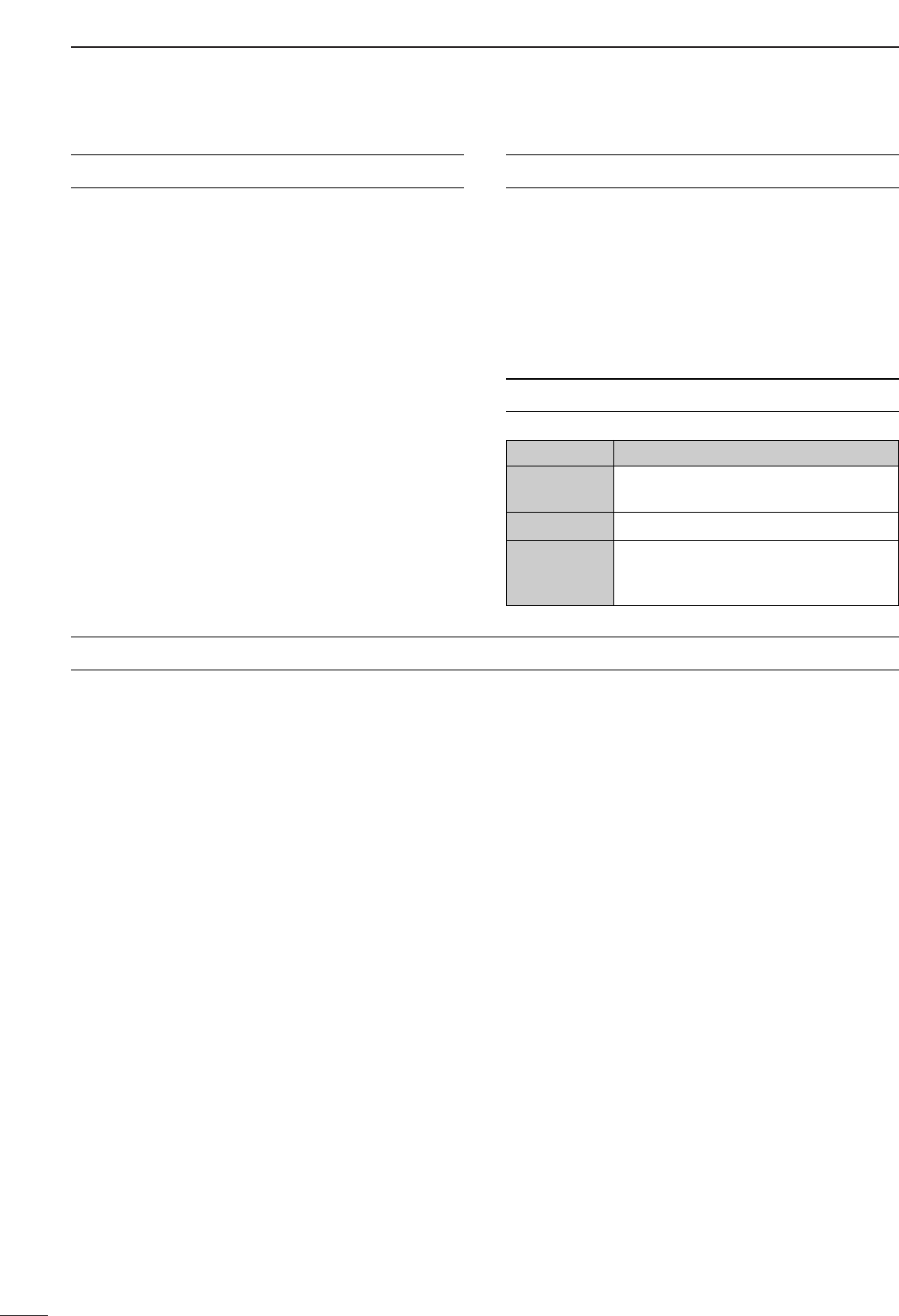
PRECAUTION
WORD DEFINITION
RR
WARNING
Personal injury, fire hazard or electric
shock may occur.
CAUTION Equipment damage may occur.
NOTE
If disregarded, inconvenience only. No
risk or personal injury, fire or electric
shock.