iii
TABLE OF CONTENTS
IMPORTANT ....................................................................................... i
EXPLICIT DEFINITIONS .................................................................... i
PRECAUTIONS .................................................................................. i
ABOUT APCO PROJECT 25 ............................................................. ii
TABLE OF CONTENTS .................................................................... iii
1 PANEL DESCRIPTION .............................................................. 1–8
■ Front panel .................................................................................. 1
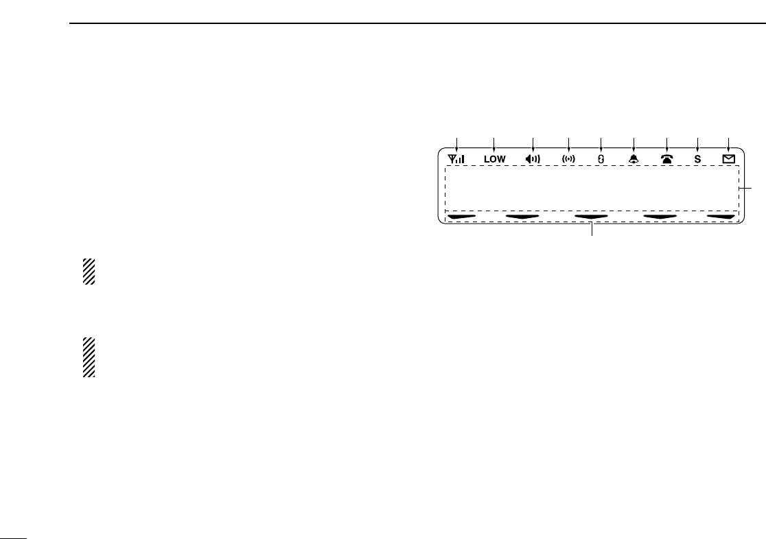
■ Function display .......................................................................... 2
■ Programmable function keys ...................................................... 3
2 BASIC OPERATION ................................................................ 9–14
■ Turning power ON ....................................................................... 9
■ Channel selection ....................................................................... 9
■ Call procedure .......................................................................... 10
■ Receiving and transmitting ....................................................... 10
D Transmitting notes .................................................................. 11
D TX code channel selection ..................................................... 11
D TX code number edit.............................................................. 12
D Individual ID code selection.................................................... 13
D Talkgroup ID code selection ................................................... 13
D DTMF transmission ................................................................ 13
■ User set mode .......................................................................... 14
■ Scrambler function .................................................................... 14
3 BIIS OPERATION ................................................................... 15–25
■ Default setting ........................................................................... 15
■ Receiving a call ......................................................................... 15
D Individual call.......................................................................... 15
D Group call............................................................................... 16
D Displaying the received call record......................................... 16
■ Transmitting a call ..................................................................... 17
D Using call memory.................................................................. 17
D Calling back from the queue channel..................................... 17
D Direct code entry .................................................................... 18
■ Receiving a message ............................................................... 19
D Receiving a status message .................................................. 19
D Receiving an SDM (Short Data Message) ............................. 19
D Received message selection.................................................. 20
■ Transmitting a status ................................................................. 21
D General................................................................................... 21
D Transmitting a status .............................................................. 21
■ Transmitting an SDM (Short Data Message) ............................. 22
D General................................................................................... 22
D Transmitting an SDM.............................................................. 22
D Programming an SDM memory.............................................. 23
■ Position data transmission ........................................................ 24
■ Printer connection ..................................................................... 24
■ Digital ANI ................................................................................. 24
■ Auto emergency transmission ................................................... 24
■ Stun function ............................................................................. 25
■ BIIS indication ........................................................................... 25
■ Priority A channel selection ....................................................... 25
■ Horn output ............................................................................... 25
4 CONNECTION AND MAINTENANCE ................................... 26–30
■ Rear panel connection .............................................................. 26
■ Supplied Accessories ................................................................ 27
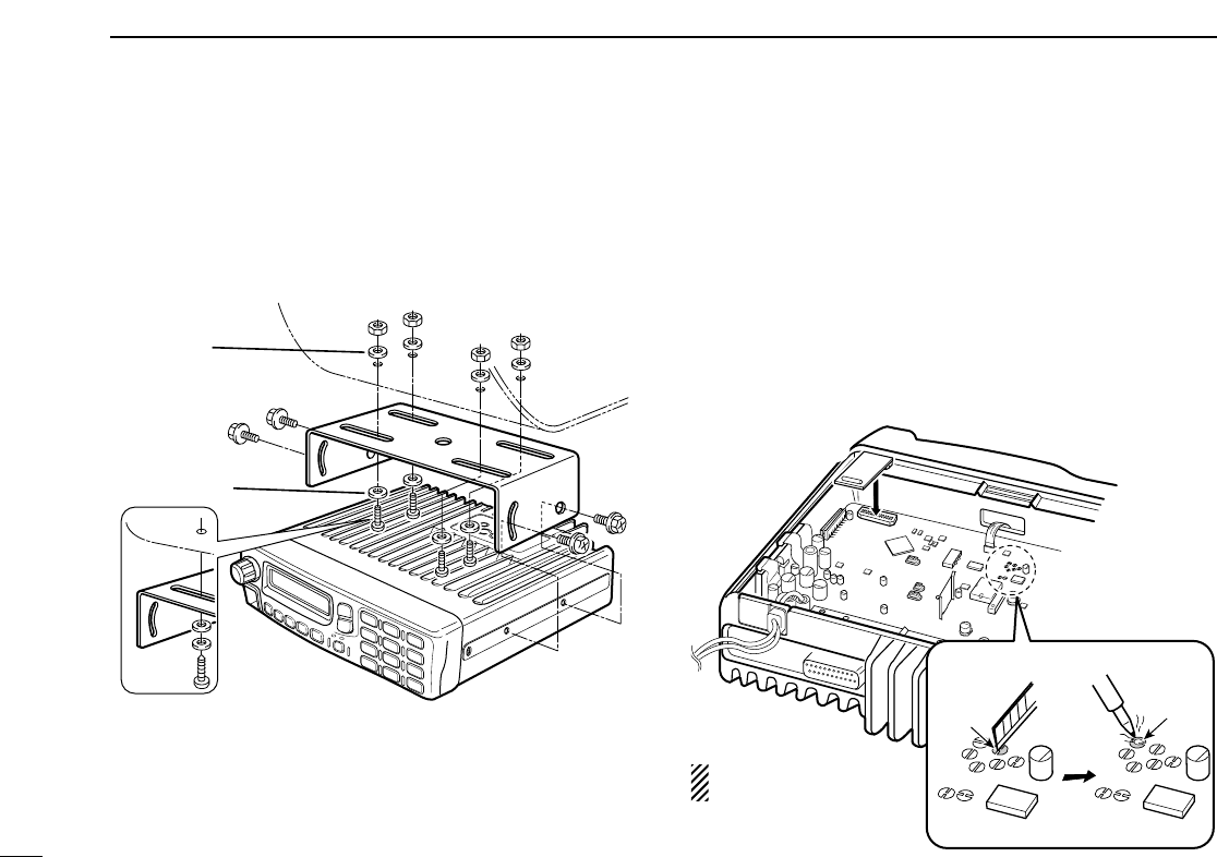
■ Mounting the transceiver ........................................................... 28
■ Optional UT-111 installation ...................................................... 28
■ Optional UT-109 or UT-110 installation ..................................... 29
■ Optional OPC-617 installation ................................................... 29
■ Antenna...................................................................................... 30
■ Fuse replacement ..................................................................... 30
■ Cleaning .................................................................................... 30
■ Options ..................................................................................... 30
5 SAFETY TRAINING INFORMATION ........................................... 31