DO NOT push the PTT when not actually desiring to trans-
mit.
AVOID using or placing the transceiver in direct sunlight or
in areas with temperatures below –30°C (–22°F) or above
+60°C (+140°F).
AVOID placing the transceiver in excessively dusty envi-
ronments.
AVOID placing the transceiver against walls. This will ob-
struct heat dissipation.
AVOID the use of chemical agents such as benzine or al-
cohol when cleaning, as they damage the transceiver sur-
faces.
BE CAREFUL! The transceiver will become hot when
operating continuously for long periods.
ii
FCC caution: Changes or modifications to this transceiver, not
expressly approved by Icom Inc., could void your authority to
operate this transceiver under FCC regulations.
TABLE OF CONTENTS
FOREWORD ........................................................................................... i
EXPLICIT DEFINITIONS ......................................................................... i
CAUTIONS .............................................................................................. i
TABLE OF CONTENTS .......................................................................... ii
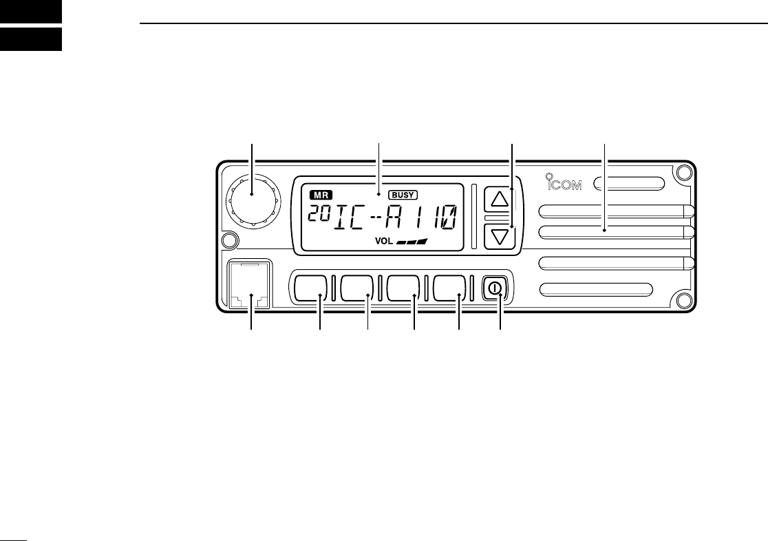
1 PANEL DESCRIPTION ................................................................ 1–3
■ Panel description .............................................................................. 1–2
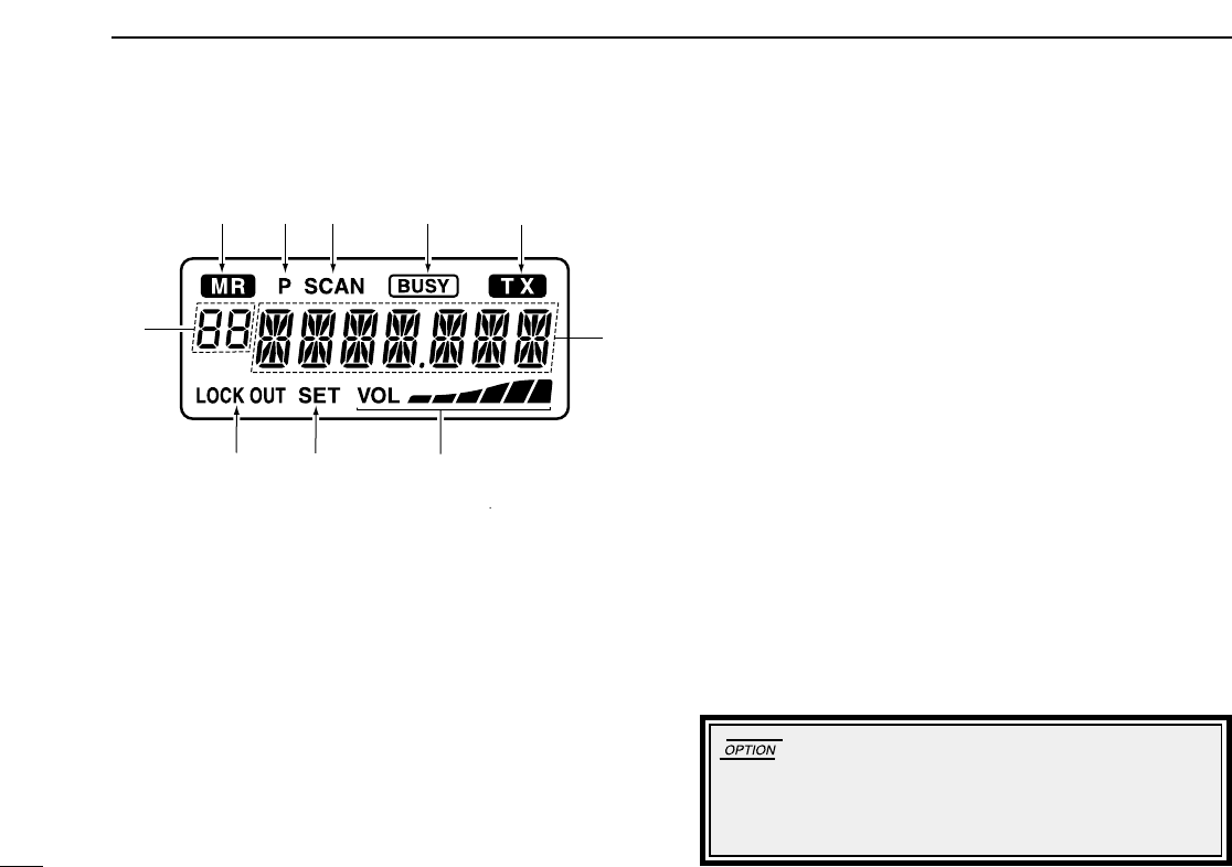
■ Function display .................................................................................... 3
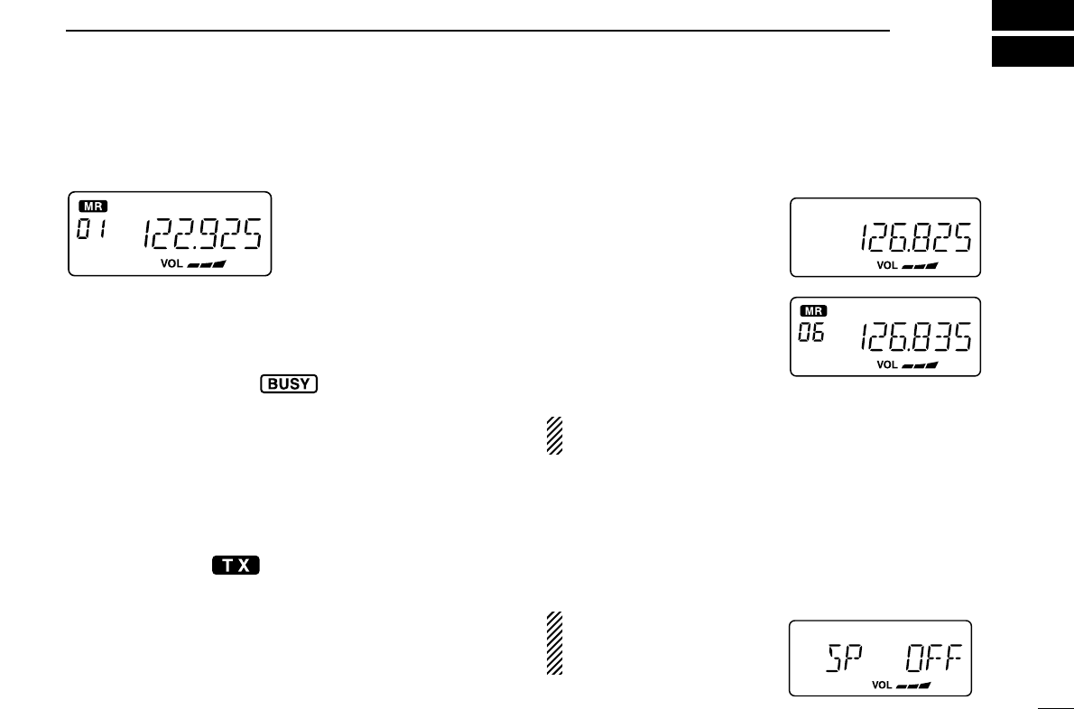
2 BASIC OPERATION ................................................................... 4–5
■ Power ON ............................................................................................. 4
■ Channel selection .................................................................................. 4
■ Squelch function .................................................................................... 5
■ Side tone function.................................................................................. 5
■ LCD backlight control ............................................................................ 5
■ Dial select function ................................................................................ 5
3 SCAN OPERATION ..................................................................... 6–7
■ Scan operation ..................................................................................... 6
■ On-hook scan ....................................................................................... 7
■ Dualwatch ............................................................................................. 7
4 MEMORY PROGRAMMING ........................................................ 8–9
■ Programming a memory channel .......................................................... 8
■ Memory names...................................................................................... 9
5 OTHER FUNCTIONS ............................................................... 10–11
■ Initial set mode ................................................................................... 10
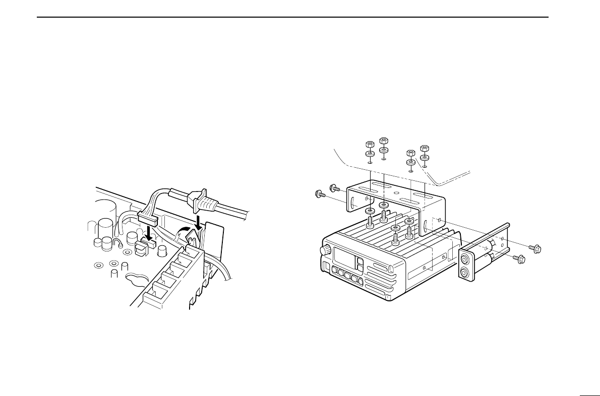
6 CONNECTION AND INSTALLATION ..................................... 12–13
■ Rear panel and connections ............................................................... 12
■ Mounting ............................................................................................. 13
■ Supplied accessories........................................................................... 13
7 CLONING ...................................................................................... 14
8 SPECIFICATIONS ............................................................ 15–16
9 OPC-871 HEADSET ADAPTER........................................ 17–18
■ OPC-871 Headset adapter .................................................................. 17
10 OPTIONS ................................................................................ 19
11 SAFETY TRAINING INFORMATION ...................................... 20