iv
■ EMR communication ………………………………………… 56
■ Low-speed data communication …………………………… 56
■ GPS operation ………………………………………………… 58
■ Other functions for DV mode operation …………………… 62
8 MEMORY/CALL CHANNELS …………………………… 64–73
■ General description ………………………………………… 64
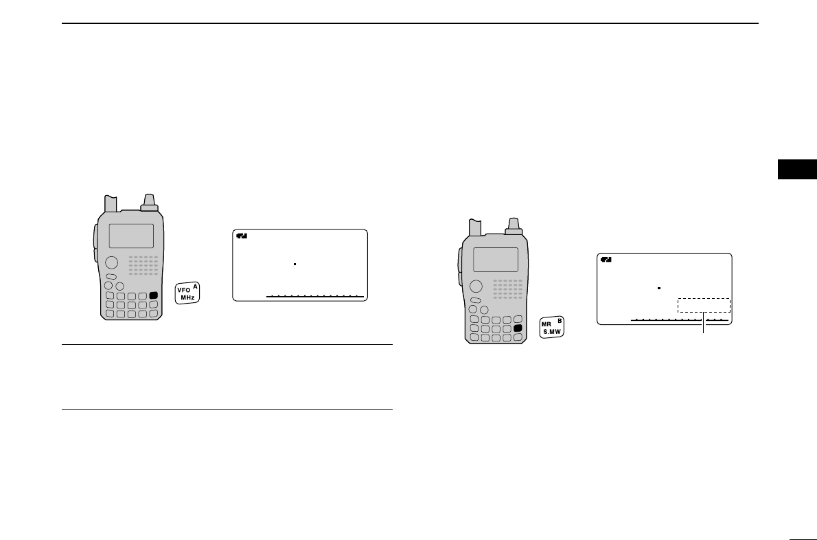
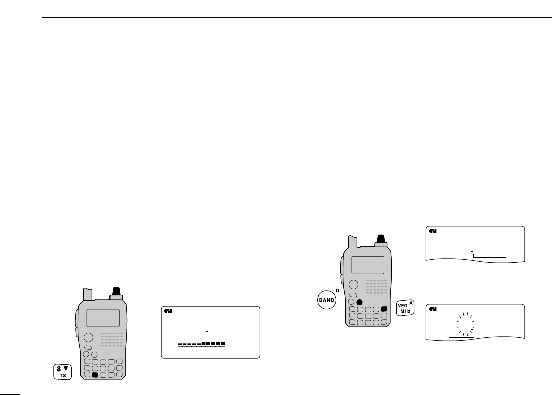
■ Selecting a memory channel ………………………………… 64
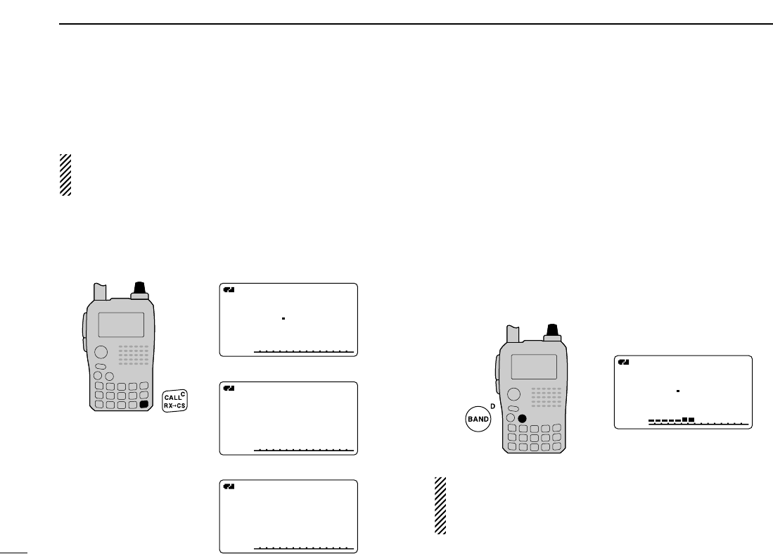
■ Selecting a call channel ……………………………………… 65
■ Memory channel programming ……………………………… 66
■ Memory bank setting ………………………………………… 67
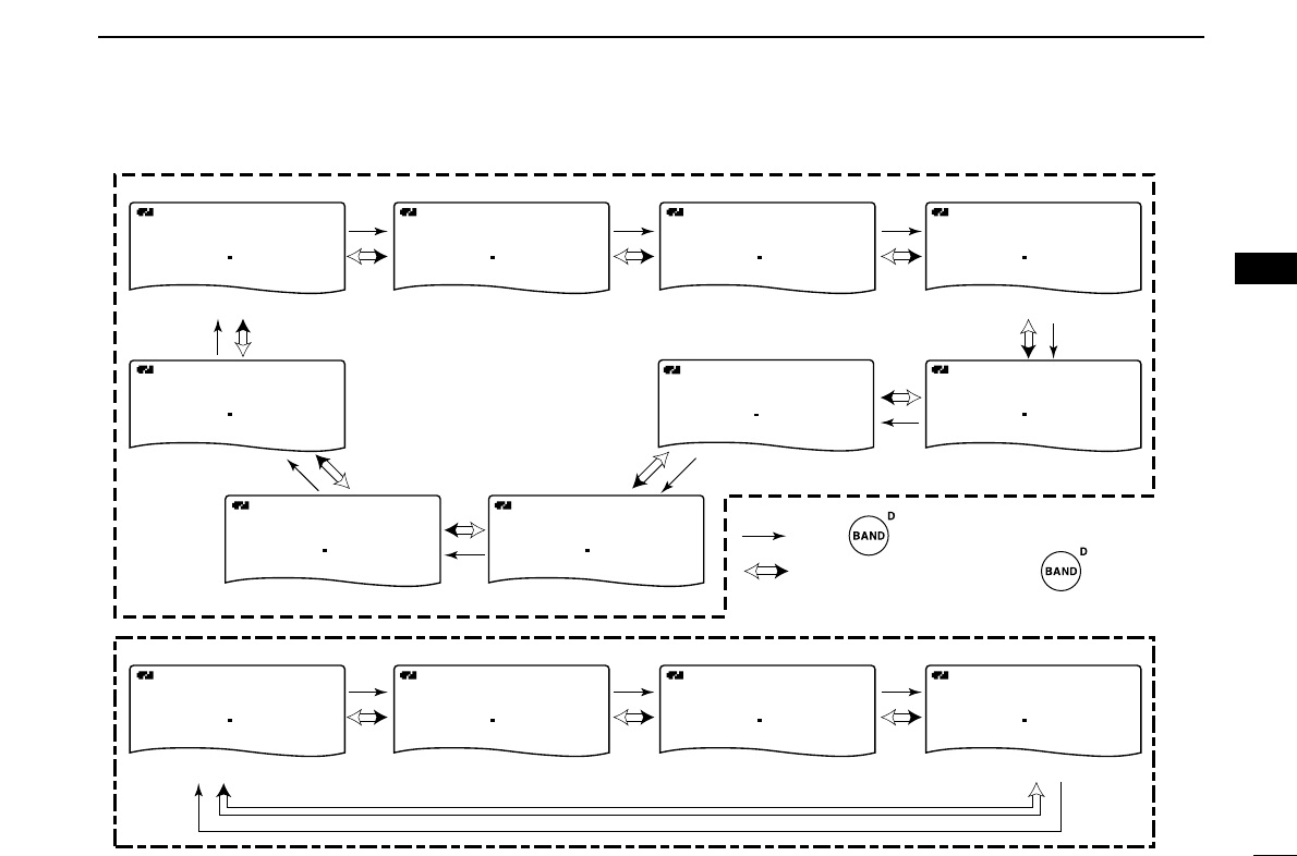
■ Memory bank selection ……………………………………… 68
■ Programming memory/bank/scan name …………………… 69
■ Selecting memory/bank name indication ………………… 70
■ Copying memory/call contents ……………………………… 71
■ Memory clearing ……………………………………………… 72
■ Erasing/transferring bank contents ………………………… 73
9 SCAN OPERATION ………………………………………… 74–81
■ Scan types …………………………………………………… 74
■ Full/band/programmed scan ………………………………… 75
■ Scan edges programming …………………………………… 76
■ Memory scan ………………………………………………… 77
■ Memory bank scan …………………………………………… 78
■ Skip channel/frequency setting ……………………………… 79
■ Scan resume condition ……………………………………… 81
10 PRIORITY WATCH ………………………………………… 82–84
■ Priority watch types ………………………………………… 82
■ Priority watch operation ……………………………………… 83
11 MENU SCREEN OPERATION ………………………… 85–102
■ General ………………………………………………………… 85
■ MENU screen indication for B band ………………………… 86
■ Menu list ……………………………………………………… 86
■ Items list ……………………………………………………… 86
■ Set mode items ……………………………………………… 88
■ DV set mode items …………………………………………… 92
■ Scan set mode items ………………………………………… 96
■ DUP/TONE set mode items ………………………………… 97
■ Display set mode items ……………………………………… 99
■ Sounds set mode items …………………………………… 102
12 OTHER FUNCTIONS …………………………………… 103–118
■ Programming a DTMF code ……………………………… 103
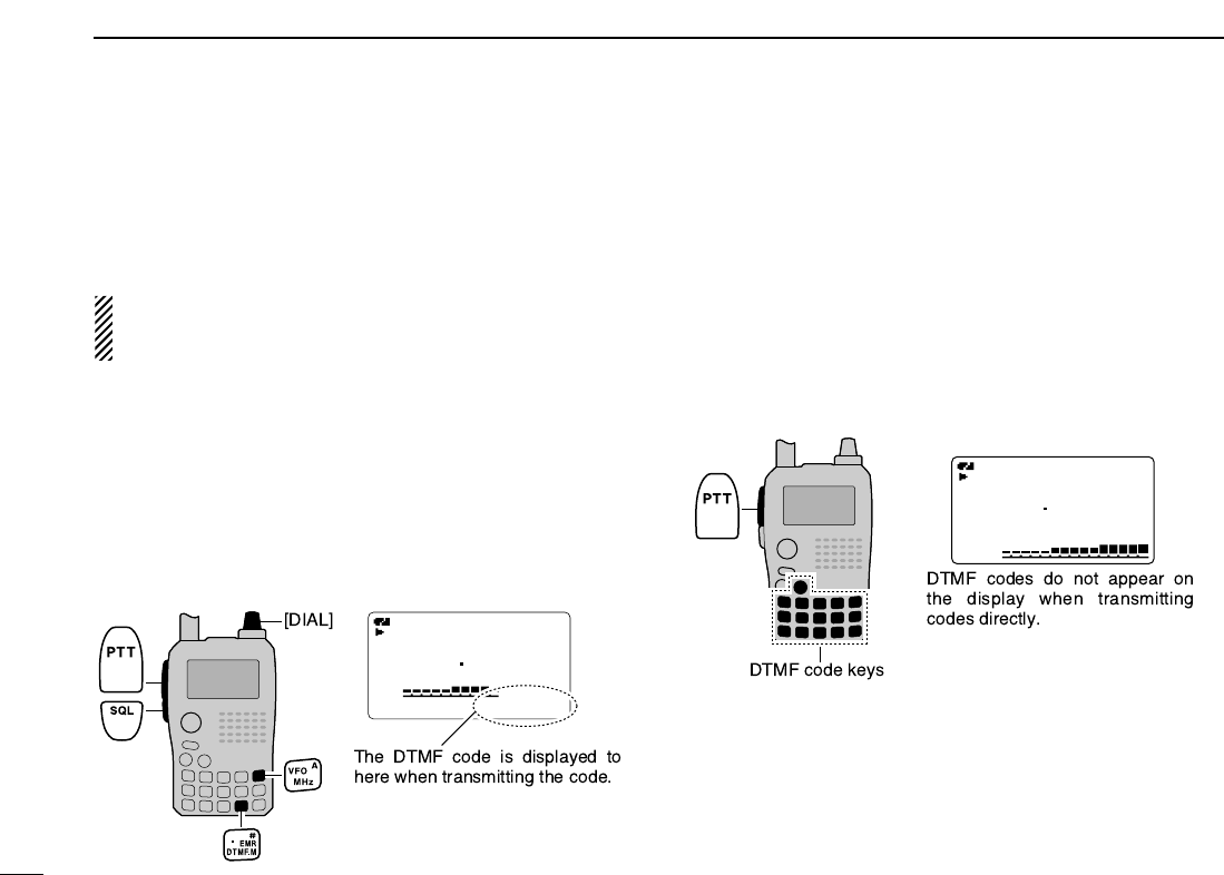
■ Transmitting a DTMF code ………………………………… 104
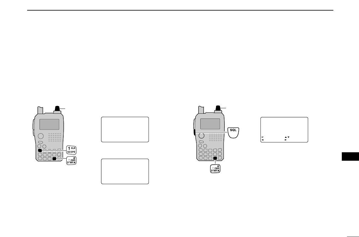
■ Clearing a DTMF memory ………………………………… 105
■ Confirming a DTMF memory ……………………………… 105
■ Setting DTMF transfer speed ……………………………… 106
■ Tone frequency and DTCS code ………………………… 106
■ Digital code and digital call sign setting ………………… 108
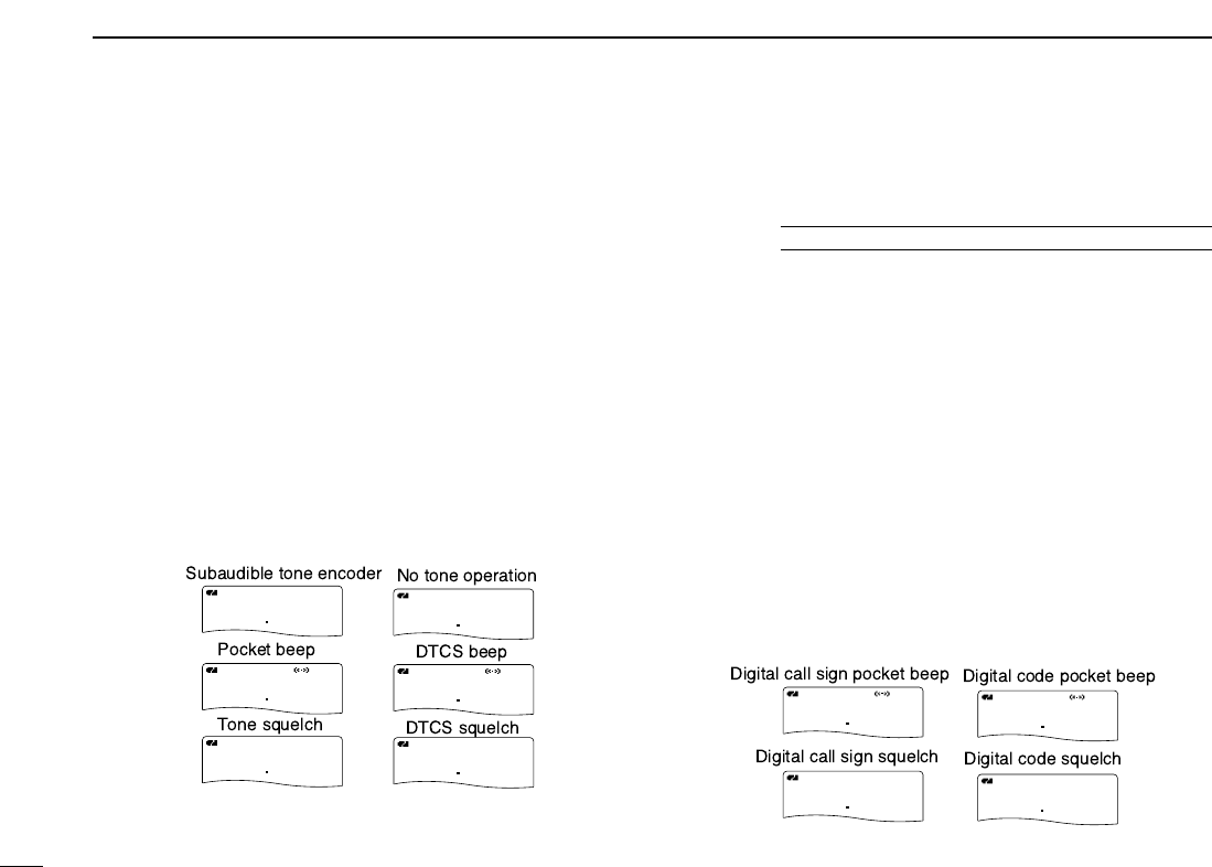
■ Tone/DTCS squelch ………………………………………… 110
■ Digital code/digital call sign squelch ……………………… 110
■ Pocket beep function ……………………………………… 111
■ DTCS polarity setting ……………………………………… 111
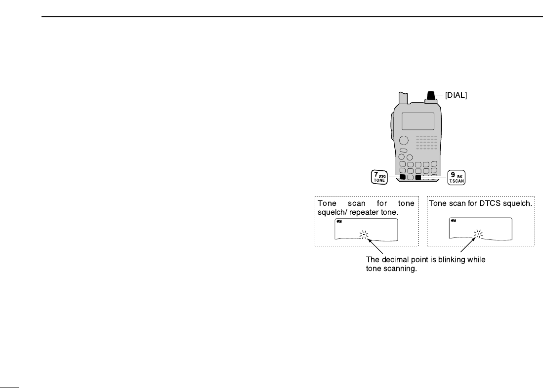
■ Tone scan …………………………………………………… 112
■ Beep tones …………………………………………………… 113
■ Dial speed acceleration …………………………………… 113
■ Key lock effect ……………………………………………… 113
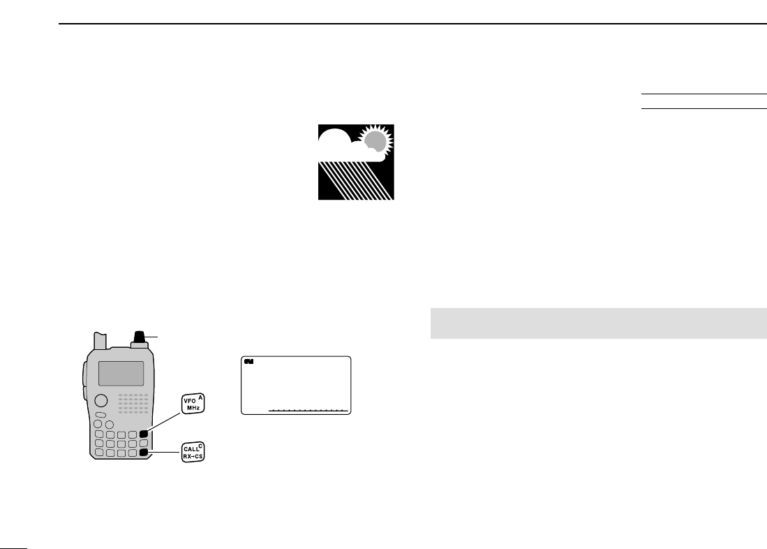
■ Weather channel operation ………………………………… 114
■ Power save ………………………………………………… 115
■ Auto power OFF …………………………………………… 116