12390
53
Verklein
Vergroot
Pagina terug
1/88
Pagina verder
INSTRUCTION MANUAL
VHF/UHF
ALL MODE TRANSCEIVER
i910H
IMPORTANT
READ THIS INSTRUCTION MANUAL
CAREFULLY before attempting to operate the
transceiver.
SAVE THIS INSTRUCTION MANUAL. This
manual contains important safety and operating in-
structions for the IC-910H.
EXPLICIT DEFINITIONS
i
R WARNING HIGH VOLTAGE! NEVER at-
tach an antenna or internal antenna connector during
transmission. This may result in an electrical shock or
burn.
R NEVER apply AC to the [DC13.8V] jack on the
transceiver rear panel. This could cause a fire or ruin
the transceiver.
R NEVER apply more than 16 V DC, such as a 24 V
battery, to the [DC13.8V] jack on the transceiver rear
panel. This could cause a fire or ruin the transceiver.
R NEVER let metal, wire or other objects touch any
internal part or connectors on the rear panel of the
transceiver. This may result in an electric shock.
R NEVER expose the transceiver to rain, snow or
any liquids.
AVOID using or placing the transceiver in areas with
temperatures below –10°C (+14°F) or above +60°C
(+140°F). Be aware that temperatures on a vehicle’s
dashboard can exceed 80°C (+176°F), resulting in per-
manent damage to the transceiver if left there for ex-
tended periods.
AVOID placing the transceiver in excessively dusty en-
vironments or in direct sunlight.
AVOID placing the transceiver against walls or putting
anything on top of the transceiver. This will obstruct
heat dissipation.
Place unit in a secure place to avoid inadvertent use
by children.
During mobile operation, DO NOT operate the trans-
ceiver without running the vehicle’s engine. When the
transceiver power is ON and your vehicle’s engine is
OFF, the vehicle’s battery will soon become ex-
hausted.
Make sure the transceiver power is OFF before start-
ing the vehicle. This will avoid possible damage to the
transceiver by ignition voltage spikes.
During maritime mobile operation, keep the transceiver
and microphone as far away as possible from the mag-
netic navigation compass to prevent erroneous indica-
tions.
BE CAREFUL! The heatsink will become hot when
operating the transceiver continuously for long periods.
BE CAREFUL! If a linear amplifier is connected, set
the transceiver’s RF output power to less than the lin-
ear amplifier’s maximum input level, otherwise, the lin-
ear amplifier will be damaged.
Use Icom microphones only (supplied or optional).
Other manufacturer’s microphones have different pin
assignments, and connection to the IC-910H may
damage the transceiver.
PRECAUTIONS
WORD
R
WARNING
CAUTION
NOTE
DEFINITION
Personal injury, fire hazard or electric
shock may occur.
If disregarded, inconvenience only.
No risk of personal injury, fire or
electric shock.
Equipment damage may occur.
SUPPLIED ACCESSORIES
The transceiver comes with the following accessories.
Qty.
q DC power cable (OPC-657A) ............................ 1
w Hand microphone (HM-36) ................................ 1
e Spare fuses (FGB 30 A) .................................... 2
r Spare fuse (FGB 4 A) ........................................ 1
1
1
TABLE OF CONTENTS
qwe
r
IMPORTANT ........................................ i
EXPLICIT DEFINITIONS ..................... i
PRECAUTIONS ................................... i
1 TABLE OF CONTENTS ................ 1
2 PANEL DESCRIPTION ........... 2 13
Front panel ..................................... 2
Function display ........................... 10
Rear panel .................................... 12
3 INSTALLATION AND
CONNECTIONS ................... 14 17
Unpacking .................................... 14
Grounding ..................................... 14
Selecting a location ...................... 14
Antenna connection ...................... 14
Required connections ................... 15
Advanced connections ................. 16
Power supply connections ............ 17
4 BASIC OPERATION ............. 18 25
Initial settings ................................ 18
When rst applying power
(CPU resetting) ............................. 18
MAIN and SUB bands .................. 19
Operating band selection ............. 20
VFO description ............................ 21
Frequency setting ......................... 22
SUB band OFF ............................. 24
SUB tuning dial ............................. 24
Dial lock function .......................... 25
5 RECEIVE AND TRANSMIT .. 26 39
Functions for receive .................... 26
RIT function .................................. 27
IF shift function ............................. 27
AGC time constant ....................... 28
AFC function ................................. 28
FM center indicator ....................... 28
Attenuator ..................................... 29
Simple band scope ....................... 29
Noise blanker ............................... 30
Tone squelch operation ................ 30
Optional DSP functions ................ 31
Functions for transmit ................... 32
Transmit via microphone .............. 32
Indications during transmit ........... 32
FM mode operation ...................... 33
VOX operation .............................. 33
Repeater operation ....................... 34
SSB mode operation .................... 36
Speech compressor ..................... 36
Split frequency operation .............. 37
Full duplex operation .................... 37
Connections for CW ..................... 38
CW mode operation ..................... 38
6 MEMORY OPERATION ........ 40 44
Memory channels ......................... 40
Operation on a memory channel .. 40
Programming in VFO mode .......... 41
Programming in memory mode .... 41
Blank channels ............................. 42
Frequency transferring ................. 42
Memory clearing ........................... 43
Call channels ................................ 43
Memo pads ................................... 44
7 SCANS ................................. 45 47
Scan types .................................... 45
Preparation ................................... 45
Programmed scan operation ........ 46
Memory scan operation ................ 46
Memory select scan ..................... 47
Tone scan ..................................... 47
8 SATELLITE OPERATION ..... 48 51
Satellite communications outline .. 48
Satellite notes ............................... 48
Entering into the satellite mode .... 48
Setting the satellite VFO ............... 49
Tracking selection ......................... 49
Preparation ................................... 50
Satellite operation ......................... 51
Satellite memory ........................... 51
9 DATA COMMUNICATION ..... 52 54
Functions for AFSK ...................... 52
Connections for AFSK .................. 52
Operating mode notes .................. 53
Operating frequency notes ........... 53
AFSK operation ............................ 53
Setting the ACC socket ................ 54
10 SET MODE ........................... 55 69
Set mode description .................... 55
General set mode ......................... 56
FM set mode ................................ 60
SSB/CW set mode ....................... 62
Scan set mode ............................. 64
Memo pad set mode ..................... 64
Compressor set mode .................. 64
VOX set mode .............................. 65
Attenuator set mode ..................... 65
Transmit set mode ........................ 66
NR set mode ................................ 67
SWP set mode ............................. 67
RIT/SHIFT set mode .................... 68
Speech set mode ......................... 69
11 OPTION INSTALLATIONS ... 70 76
Internal view ................................. 70
Opening the transceivers case .... 71
UT-102
VOICE SYNTHESIZER
UNIT
.............................................. 71
UT-106 DSP UNIT .......................... 72
UX-910 1200 MHz BAND UNIT
........ 73
CR-293
HIGH STABILITY CRYSTAL
UNIT
.............................................. 74
FL-132/FL-133
CW NARROW
FILTER
........................................... 75
12 MAINTENANCE ................... 76 77
Troubleshooting ............................ 76
Fuse replacement ......................... 77
CPU resetting ............................... 77
13 CONTROL COMMAND ........ 78 79
Remote jack (CI-V) information .... 78
14 SPECIFICATIONS ....................... 80
15 OPTIONS ..................................... 81
16 INSTALLATION NOTES ....... 82 83
Front panel
q POWER SWITCH [POWER]
Push momentarily to turn power ON.
Push for 2 sec. to turn power OFF.
w TRANSMIT SWITCH [TRANSMIT]
Push to select transmitting or receiving.
e COMPRESSION SWITCH [COMP] (p. 36)
Push to switch the speech compressor function ON
and OFF.
The speech compressor increases average RF output
power, improving signal strength and readability in SSB.
r VOX SWITCH [VOX] (p. 33)
Push to switch the VOX function ON and OFF.
The VOX (Voice-Operated Transmission) function tog-
gles between transmit and receive with your voice. This
function provides an opportunity to input log entries into
your computer, etc., while operating.
t HEADPHONE JACK [PHONES]
Accepts headphones.
Output power: 5 mW with 816 load.
When headphones are connected, the internal speaker
or connected external speaker does not function.
The MAIN and SUB band audio can be mixed or sepa-
rated when using stereo headphones according to set
mode settings. (p. 57)
y MICROPHONE CONNECTOR [MIC]
Accepts the supplied or optional microphone.
See p. 81 for appropriate microphones.
See p. 15 for microphone connector information.
u MIC GAIN CONTROL [MIC GAIN]
Adjusts microphone input gain.
How to set the microphone gain.
Set the [MIC] control so that the [MAIN]/[SUB] indicator (ALC
indicator) some times lights brighter during normal voice
transmission in SSB mode.
i RF POWER CONTROL [RF PWR]
Continuously varies the RF output power from min-
imum to maximum.
144 MHz band 5100 W
430(440) MHz band 575 W
1200 MHz band 110 W
(optional UX-910)
RF PWR
IncreasesDecreases
MIC GAIN
Recommended level for
an Icom microphone
IncreasesDecreases
2
2
PANEL DESCRIPTION
q
o
!0
!1 !2
!3
w
e
r
t
y
u
i
o MAIN BAND INDICATOR [MAIN]
Lights green while the squelch is opened or a sig-
nal is received on the MAIN band; lights red while
transmitting on the MAIN band.
While transmitting, the indicator also shows ALC con-
dition. Brightness increases more than usual when
the ALC function is activated.
Flashes when an off-frequency signal is received
and the FM center detector is activated. (p. 28)
!0 RF GAIN CONTROL/SQUELCH CONTROL
[RF/SQL] (outer control)
Adjusts the RF gain and squelch threshold level for
the MAIN band. The squelch removes noise output
from the speaker (closed condition) when no signal
is received.
The squelch is particularly effective for FM. It is also
available for other modes.
12 to 13 oclock position is recommended for any setting
of the [RF/SQL] control.
The squelch threshold position for SSB/CW mode can
be set from 12 or 13 oclock position in SSB/CW set
mode. (p. 62)
The control can be set as Auto(RF gain control in SSB
and CW; squelch control in FM) or squelch control (RF
gain is xed at maximum) in set mode as follows. (p. 56)
When setting as RF gain/squelch control
When functioning as RF gain control
(Squelch is xed open; SSB, CW only)
When functioning as squelch control
(RF gain is xed at maximum.)
!1 AF CONTROL [AF] (inner control)
Varies the audio output level from the speaker for
the MAIN band.
!2 SUB BAND INDICATOR [SUB]
Lights green while the squelch is opened or a signal
is received on the SUB band; lights red while trans-
mitting in satellite operation.
!3 RF GAIN CONTROL/SQUELCH CONTROL
[RF/SQL] (outer control)
Adjusts the RF gain and squelch threshold level for
the SUB band. The squelch removes noise output
from the speaker (closed condition) when no signal
is received.
AF RF/SQL
No audio output
Max. audio output
Decreases Increases
Squelch is
open.
S-meter
squelch
S-meter squelch
threshold
Noise squelch
threshold
Shallow Deep
Noise squelch
Minimum RF gain
Adjustable
range
Maximum
RF gain
Recommended level
RF gain
adjustable
range (SSB,
CW modes)
Maximum
RF gain
S-meter
squelch
Noise squelch (FM mode)
Squelch is
open.
MODE
SSB, CW
FM
AUTO
RF GAIN
SQL
SQL
SET MODE SETTING
SQL
SQL
RF GAIN + SQL
RF GAIN + SQL
SQL
3
2
PANEL DESCRIPTION
4
2
PANEL DESCRIPTION
Front panel (continued)
!4 AF CONTROL [AF] (inner control)
Varies the audio output level from the speaker for
the SUB band.
!5 SETMENU SWITCH [SETMENU] (p. 55)
Push this switch then one of [FM],
[SSB/CW], [RIT], [SCAN], [NR], [TRANS-
MIT], [COMP], [VOX], [ATT], [SWP],
[MPW] or [SPCH] to enter the indepen-
dent item set mode.
Push for 1 sec. to enter the set mode for
commonly used item settings.
!6 ATTENUATORPRE-AMP SWITCH [ATTP.AMP]
Push to switch the attenuator function
ON and OFF. (p. 29) Use this function to
protect from signal distortion from exces-
sively strong signals.
The attenuation level is independently ad-
justable for 144 MHz or 430(440) MHz band
in the ATT set mode. The optional 1200 MHz
band attenuation level is xed and is approx.
20 dB. (p. 65)
Push for 1 sec. to switch the connected
pre-amplier ON and OFF, when an op-
tional pre-amplifier unit, AG-25, AG-35
and/or AG-1200, is connected. (p. 16)
DO NOT connect any equipment, such as an SWR
or power meter between the transceiver and pream-
plier. In such case, the preamplier may not acti-
vate properly.
!7 AUTO FREQUENCY CONTROL/NOISE
BLANKERNOISE REDUCTION SWITCH
[AFC/NBNR]
During FM/FM narrow mode operation,
push to switch the AFC (Automatic Fre-
quency Control) function ON and OFF.
(p. 28)
Automatically tunes the operating frequency,
when an off-frequency signal is received, in
100 kHz steps. This function also follows the
signal even if the frequency is shifted.
During SSB or CW mode operation, push
to switch the noise blanker function ON
and OFF. (p. 30)
Reduces pulse-type noise, such as ignition
noise from a vehicle.
Push for 1 sec. to switch the noise re-
duction function ON and OFF when an
optional DSP unit, UT-106, is installed.
(p. 31)
Reduces unwanted noise and pulls out the
desired signal only for clear readability.
For 1 sec.
For 1 sec.
For 1 sec.
!4
!5
!6
!7
!8
!9
@0
@1
@2
@3
5
2
PANEL DESCRIPTION
!8 AUTO GAIN CONTROLAUTO NOTCH FILTER
SWITCH [AGCANF]
Push to switch the time constant of the
automatic gain control to SLOW and
FAST for the MAIN band.* (p. 28)
SLOW selection (FAGC disappears) during
SSB (USB or LSB) operation, FAST selection
(FAGC appears) during CW, data operation
and while tuning with fast tuning dial rotation
are recommended.
*The AGC time constant can be selected on the
MAIN band only. FAST selection is fixed on
the SUB band.
Push for 1 sec. to switch the automatic
notch filter function ON and OFF when
the optional DSP unit, UT-106, is in-
stalled. (p. 31)
Reduces interference signals such as beat,
RTTY or CW signals and the notch frequency
automatically follows the interfering signal.
!9 kHz/MHzTUNING STEP SELECTION SWITCH
[kHz/MHz] (p. 22)
Push to select tuning step for the tuning
dial or scanning from 1 kHz, 1 MHz step
and regular tuning step* in sequence
•“
ZZ
appears above the 1 kHz or 1 MHz digit
when 1 kHz or 1 MHz tuning step is selected,
respectively.
*The regular tuning step is selected for each
operating mode as follows.
Push for 1 sec. to enter the regular tun-
ing step selection mode.
The tuning step can be selected for each op-
erating mode independently.
SSB/CW mode: 1, 10, 50 and 100 Hz step;
FM mode: 0.1, 5, 6.25, 10, 12.5, 20, 25 and
100 kHz step can be selected by rotating the
tuning dial.
@0 SPEECHLOCK SWITCH [SPCHLOCK]
Announces the receiving signal strength
and/or selected readout frequency when
the optional UT-102 is installed. (pgs. 69,
71)
Push for 1 sec. to switch the tuning dial
lock function ON and OFF to prevent ac-
cidental setting changes. (p. 25)
@1 TUNING DIAL
Changes the displayed frequency, selects set mode
items, etc.
@2 BRAKE ADJUSTMENT SCREW
Adjust the tension of the tuning dial.
Rotate clockwise to increase the tension; counterclock-
wise to decrease the tension.
@3 MEMORY CHANNEL UP/DOWN SWITCHES
[
YY
UP]/[DOWN
ZZ
] (p. 40)
Push [Y UP] to change the memory
channel up; push [DOWN Z] to change
the memory channel down.
Memory channel changes continuously while
holding either switch.
Memory channels can be selected both in
VFO and memory modes.
For 1 sec.
or
or
Brake adjustment screw
For 1 sec.
For 1 sec.
For 1 sec.
6
2
PANEL DESCRIPTION
@4 RIT CONTROL [RIT] (p. 27)
Shifts the receive frequency without changing the
transmit frequency for the MAIN band only while the
RIT function is activated.
SSB/CW mode : ±1.0 kHz* in 10 Hz step
FM mode : ±5.0 kHz* in 50 Hz step
*For 1200 MHz band; ±2.0 kHz and ±10.0 kHz, respec-
tively when the optional UX-910 is installed.
By using the Sub dial function, the RIT control can be
used as the MAIN/SUB tuning dial or the SUB band IF
shift control. See page 24 for details.
@5 IF SHIFT CONTROL [SHIFT]
Shifts the center frequency of the receivers IF
passband within 1.2 kHz range.
By using the Sub dial function, the IF shift control can be
used as the MAIN/SUB tuning dial or the SUB band IF
shift control. See page 24 for details.
What is the Sub dial function?
The [RIT] and [SHIFT] controls are used for RIT and IF shift
controls for the MAIN band by default. However, the Sub dial
function assigns these controls as the MAIN/SUB tuning dial
or the SUB band IF shift control. (p. 24, 68)
@6 SATELLITE SWITCH [SATELLITE]
Push to enter satellite mode (RX on
MAIN, TX on SUB band). Push again to
return to the condition before entering
into the satellite mode.
Push to enter satellite mode using the
current operating frequencies when
pushing for 1 sec.
To change the normal and reverse satellite
operations, push [F-INP/ENT] for 1 sec.
@7 RIT SWITCH [RIT] (p. 27)
Push to switch the RIT control activity ON
and OFF.
•“RIT indicator appears when the RIT func-
tion is in use.
Push for 1 sec. to switch the Sub dial
function ON and OFF.
•“RIT indicator flashes and the [RIT] and
[SHIFT] controllers acts as the controllers
specied in the RIT/SHIFT set mode. (p. 68)
@8 KEYPAD
Numeral and other function keys for tuning and ac-
tivating functions.
See the table at right.
For 1 sec.
For 1 sec.
For 1 sec.
RIT S
H
IFT
RIT S
H
IFT
RIT S
H
IFT
Center positionMax. counter-
clockwise position
Max. clockwise
position
Front panel (continued)
@4
@5
@6
@8
@7
7
2
PANEL DESCRIPTION
Enters numeral 1 when entering an operating
frequency. (p. 23)
Switches between VFO and memory mode.
(p. 40)
Enters numeral 2 when entering an operating
frequency. (p. 23)
Enters numeral 3 when entering an operating
frequency. (p. 23)
Switches between VFO A and B during VFO
mode operation. (p. 21)
Enters numeral 4 when entering an operating
frequency. (p. 23)
Enters numeral 5 when entering an operating
frequency. (p. 23)
Enters numeral 6 when entering an operating
frequency. (p. 23)
Enters numeral 7 when entering an operating
frequency. (p. 23)
Enters numeral 8 when entering an operating
frequency. (p. 23)
Stores the displayed operating conditions into
MEMO PAD channel (p. 44)
Enters numeral 9 when entering an operating
frequency. (p. 23)
Re-calls the contents in the MEMO PAD channel.
(p. 44)
Enters decimal point . for entering below the
MHz digits when entering an operating fre-
quency.
Starts and cancels scanning function. (p. 46)
Turns OFF the SUB band frequency indication
during satellite operation. In this case, only the
MAIN band frequency can be tuned by rotating
the tuning dial. (p. 49)
Enters numeral 0 when entering an operating
frequency. (p. 23)
Switches sweep function for the bandscope ON
and OFF. (p. 29)
Turns OFF the MAIN band frequency indication
during satellite operation. In this case, only the
SUB band frequency can be tuned by rotating
the tuning dial. (p. 49)
Enables operating frequency entering from the
keypad. See page 23 for details.
Equalizes the condition of the VFO A and B.
(p. 21)
Shows 10 Hz and 1 Hz digits of operating fre-
quency on both the MAIN and SUB bands while
pushing and holding. (p. 22)
Stores the set conditions into a memory channel.
(p. 41)
Clears stored contents of memory channel to be
a blank channel. (p. 43)
Transfers the contents of a memory channel into
either the VFO A or B. (p. 42)
Opens squelch for monitoring the operating or
transmit frequency, and the frequency indication
automatically changes to transmit frequency in the
case of duplex or split operation. (p. 34)
Starts and cancels tone scan when the repeater
tone or tone squelch is activated in FM (narrow)
operation. (p. 47)
Used to change memory channel during memory
mode operation by rotating the tuning dial while
pushing and holding. (p. 40)
Switch Switch action when pushed Switch action when pushed for 1 sec.
8
2
PANEL DESCRIPTION
@9 SPLITDUPLEX SWITCH [SPLITDUP]
Push to turn the split function, with the
VFO A and B, ON and OFF. (p. 37)
The split operation is not available for the
SUB band.
Push for 1 sec. to select the duplex (re-
peater) direction or to turn the function
OFF. (p. 34)
The duplex operation is not available for the
SUB band.
#0 SSB/CWCW-NARROW SWITCH
[SSB/CWCW-N]
Push to switch the operating mode be-
tween SSB and CW. (p. 23)
Push for 1 sec. to switch the operating
mode between USB and LSB or between
CW and CW narrow during SSB or CW
mode, respectively.
#1 FMFM-NARROW SWITCH [FMFM-N] (p. 23)
Push to switch the operating mode be-
tween FM and FM repeater mode.
The duplex operation can be made in MAIN
band only, it cannot be operated in SUB
band.
Push for 1 sec. to switch the operating
mode between FM and FM-N (FM nar-
row).
The FM-N mode cannot be selected in
1200 MHz band operation.
#2 TONE SWITCH [TONE] (p. 34)
Push to turn the tone encoder function
ON and OFF in FM mode. (except Eu-
rope, Sweden and Italy versions)
•“T indicator appears in the display when the
tone encoder is activated.
Push to transmit a 1750 Hz repeater tone
in FM mode for European, Sweden and
Italy versions.
Available repeater tones (Unit: Hz)
#3 MAIN/SUB CHANGEBAND SWITCH
[M/SBAND]
Push to replace the MAIN bands fre-
quency and mode with the SUB bands.
(p. 19)
Push for 1 sec. to change the operating
band during single band operation or
when the optional band unit, UX-910, is
installed. (p. 20)
For 1 sec.
For 1 sec.
For 1 sec.
For 1 sec.
#5
#4
#3
#2
#1
#0
@9
67.0
69.3
71.9
74.4
77.0
79.7
82.5
085.4
088.5
091.5
094.8
097.4
100.0
103.5
107.2
110.9
114.8
118.8
123.0
127.3
131.8
136.5
141.3
146.2
151.4
156.7
159.8
162.2
165.5
167.9
171.3
173.8
177.3
179.9
183.5
186.2
189.9
192.8
196.6
199.5
203.5
206.5
210.7
218.1
225.7
229.1
233.6
241.8
250.3
254.1
Front panel (continued)
9
2
PANEL DESCRIPTION
#4 SUBSUB OFF SWITCH [SUBSUB OFF]
Push to enable the SUB band control
from the tuning dial, keypad, etc. (p. 19)
•“SUB indicator appears.
Push for 1 sec. to turn the SUB band
readout indication ON and OFF. (p. 24)
#5 CALLTONE SQUELCH SWITCH [CALLT-SQL]
Push to select the call channel of the op-
erating band. The call channel can be se-
lected from both the VFO and memory
mode operation. (p. 43)
Push for 1 sec. to turn the tone squelch
function ON and OFF during FM mode
operation. (p. 30)
•“T-SQL indicator appears when the tone
squelch is activated.
For 1 sec.
For 1 sec.
16
3
INSTALLATION AND CONNECTIONS
MB-23 CARRYING HANDLE
PREAMP (p. 59)
(144 MHz/430(440) MHz/1200 MHz)
EXTERNAL SPEAKER
(MAIN/SUB) (p. 12)
CT-17
144 MHz : AG-25
430(440) MHz : AG-35
1200 MHz : AG-1200
External all-weather, mast
mounting preamplifiers are
available.
MAIN
MAIN
144 MHz430(440) MHz 1200 MHz (optional)
SUB
SUB
s
p
-
7
i
c
o
m
Use 48 speakers.
[REMOTE] (p. 78)
Used for computer control and transceive
operation.
Used for external
equipment control.
ACC SOCKETS
(pgs. 13, 52)
DATA SOCKETS
(MAIN/SUB) (pgs. 13, 52)
CAUTION: NEVER
connect equipment
(i.e. power, SWR meter)
between transceiver
and preamplifier.
Advanced connections
Front panel
Rear panel
51
8
SATELLITE OPERATION
Satellite operation
When your own signal can be received with a loop
test, satellite communication can be performed.
q Rotate the tuning dial to re-tune the uplink fre-
quency after pushing [SWP 0 S], when shifting a
frequency with the Doppler effect.
The downlink frequency readout (MAIN band) disap-
pears.
w Rotate the tuning dial to re-tune the downlink fre-
quency after pushing [SCAN . S], when the oper-
ating stations signal frequency is shifted.
RIT function can also be used for downlink frequency
tuning within ±1 kHz range.
Satellite memory
The IC-910H has 10 satellite memory channels to
memorize both uplink and downlink frequencies and
operating modes, etc.
DD
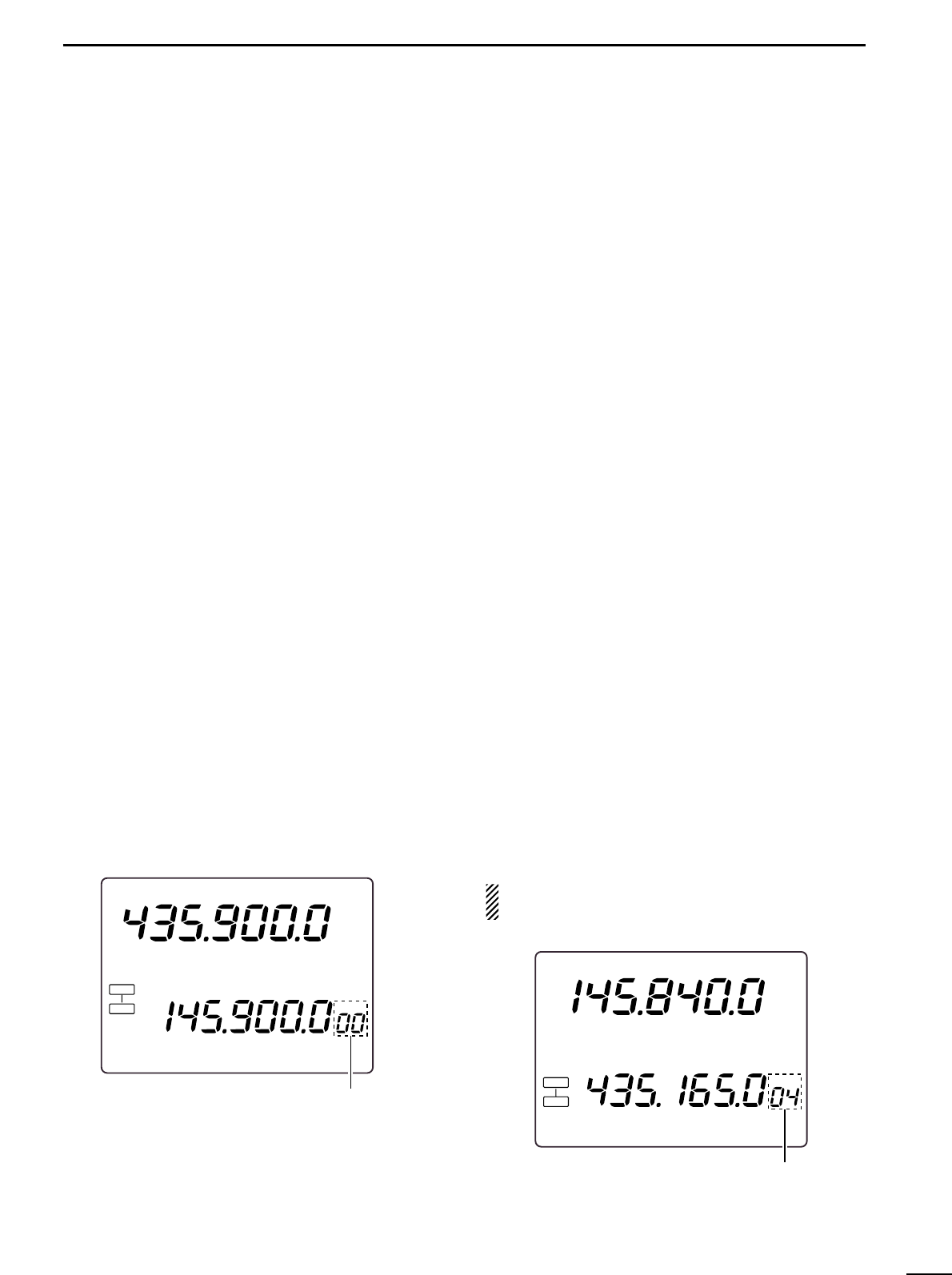
Satellite memory selection
q Push [SATELLITE] to enter the satellite mode.
w Push [V/M 1] to select satellite memory mode.
•“MEMO indicator and memory channel number are dis-
played beside the uplink frequency (SUB band) indica-
tion.
Push [V/M 1] again to select satellite VFO.
e Push [DN ] or [ UP] to select the desired satel-
lite mode memory channel.
The channels 0009 are selectable.
By pushing and holding either switch, the satellite mem-
ory channel changes continuously.
DD
Satellite memory programming
q Select the desired satellite memory channel.
Push [SATELLITE] to enter the satellite mode.
Push [V/M 1] to select satellite VFO mode.
Push [DN ] or [ UP] to select the desired satellite
mode memory channel.
w Set the desired downlink frequency to the MAIN
band and uplink frequency to the SUB band, as well
as operating mode.
Push [SCAN . M] for downlink tuning, push [SWP 0 S]
for uplink frequency tuning.
Push [SUB] before the operating mode selection when
selecting operating mode for the uplink.
e Push [MW 4] for 1 sec. to program the set contents
to the satellite memory channel.
3 beep tones sound.
NOTE: Tracking selection, normal or reverse, is not
programmed in the satellite memory channels.
USBUSB
M
E
MO
L
SB
S
A
T
L
RE
V
S 1 3
5
7
9 2020
4040
60dB60dB
60dB
S
1
3 5
7
9
20
40
Select the desired
satellite memory
USBUSB
M
E
MO
L
SB
NOR
S
A
T
L
S 1 3
5
7
9 2020
4040
60dB60dB
60dB
S
1
3 5
7
9
20
40
Satellite memory
indication
53

Hulp nodig? Stel uw vraag in het forum

Spelregels

Misbruik melden

Gebruikershandleiding.com neemt misbruik van zijn services uitermate serieus. U kunt hieronder aangeven waarom deze vraag ongepast is. Wij controleren de vraag en zonodig wordt deze verwijderd.

Product:

Bijvoorbeeld antisemitische inhoud, racistische inhoud, of materiaal dat gewelddadige fysieke handelingen tot gevolg kan hebben.

Bijvoorbeeld een creditcardnummer, een persoonlijk identificatienummer, of een geheim adres. E-mailadressen en volledige namen worden niet als privégegevens beschouwd.

Spelregels forum

Om tot zinvolle vragen te komen hanteren wij de volgende spelregels:

Belangrijk! Als er een antwoord wordt gegeven op uw vraag, dan is het voor de gever van het antwoord nuttig om te weten als u er wel (of niet) mee geholpen bent! Wij vragen u dus ook te reageren op een antwoord.

Belangrijk! Antwoorden worden ook per e-mail naar abonnees gestuurd. Laat uw emailadres achter op deze site, zodat u op de hoogte blijft. U krijgt dan ook andere vragen en antwoorden te zien.

Abonneren

Abonneer u voor het ontvangen van emails voor uw Icom IC-910H bij:


U ontvangt een email met instructies om u voor één of beide opties in te schrijven.


Ontvang uw handleiding per email

Vul uw emailadres in en ontvang de handleiding van Icom IC-910H in de taal/talen: Engels als bijlage per email.

De handleiding is 2,81 mb groot.


U ontvangt de handleiding per email binnen enkele minuten. Als u geen email heeft ontvangen, dan heeft u waarschijnlijk een verkeerd emailadres ingevuld of is uw mailbox te vol. Daarnaast kan het zijn dat uw internetprovider een maximum heeft aan de grootte per email. Omdat hier een handleiding wordt meegestuurd, kan het voorkomen dat de email groter is dan toegestaan bij uw provider.

Stel vragen via chat aan uw handleiding

Stel uw vraag over deze PDF

Uw handleiding is per email verstuurd. Controleer uw email

Als u niet binnen een kwartier uw email met handleiding ontvangen heeft, kan het zijn dat u een verkeerd emailadres heeft ingevuld of dat uw emailprovider een maximum grootte per email heeft ingesteld die kleiner is dan de grootte van de handleiding.

Er is een email naar u verstuurd om uw inschrijving definitief te maken.

Controleer uw email en volg de aanwijzingen op om uw inschrijving definitief te maken

U heeft geen emailadres opgegeven

Als u de handleiding per email wilt ontvangen, vul dan een geldig emailadres in.

Uw vraag is op deze pagina toegevoegd

Wilt u een email ontvangen bij een antwoord en/of nieuwe vragen? Vul dan hier uw emailadres in.


Info