IMPORTANT ........................................ i
EXPLICIT DEFINITIONS ..................... i
PRECAUTIONS ................................... i
1 TABLE OF CONTENTS ................ 1
2 PANEL DESCRIPTION ........... 2– 13
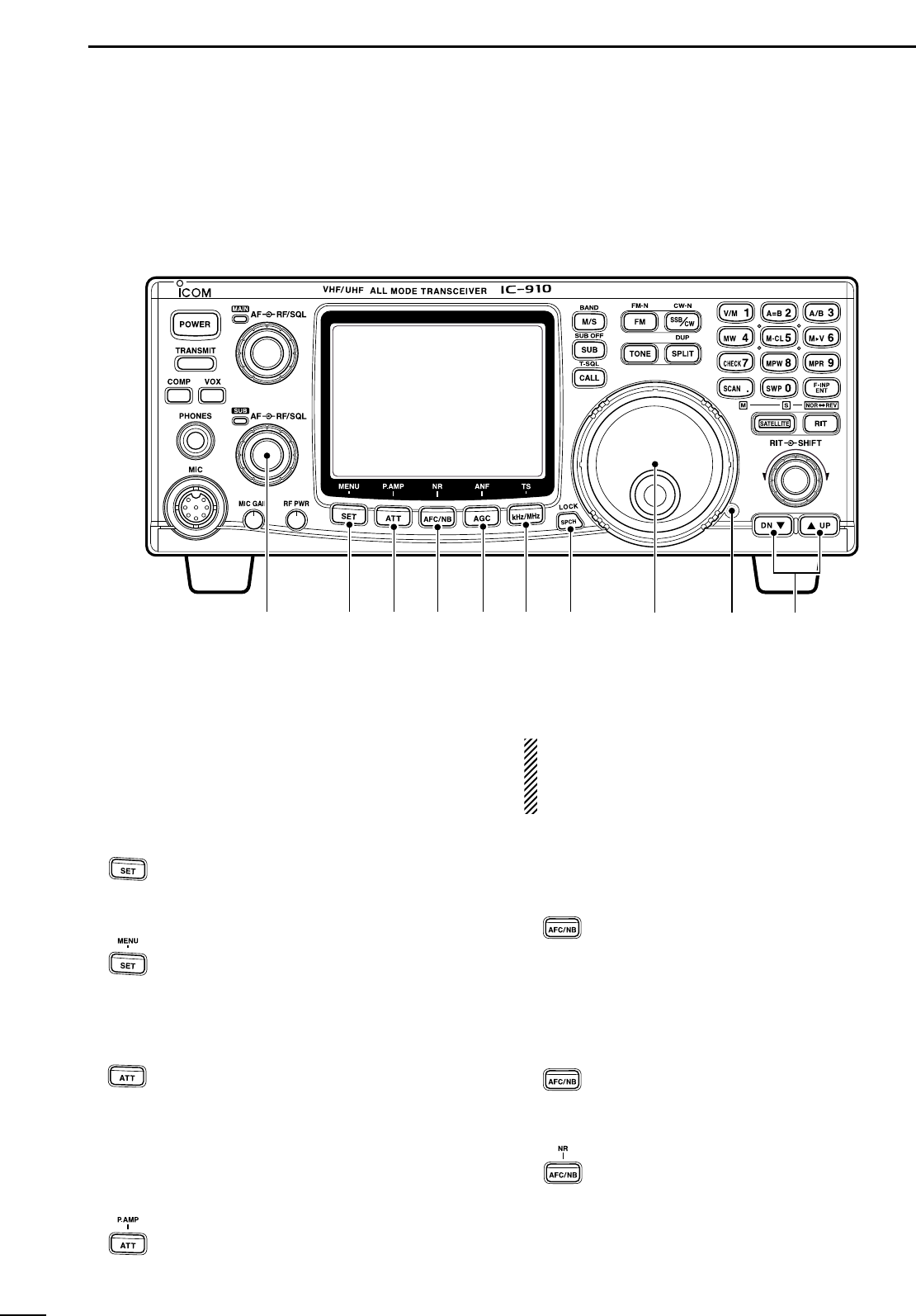
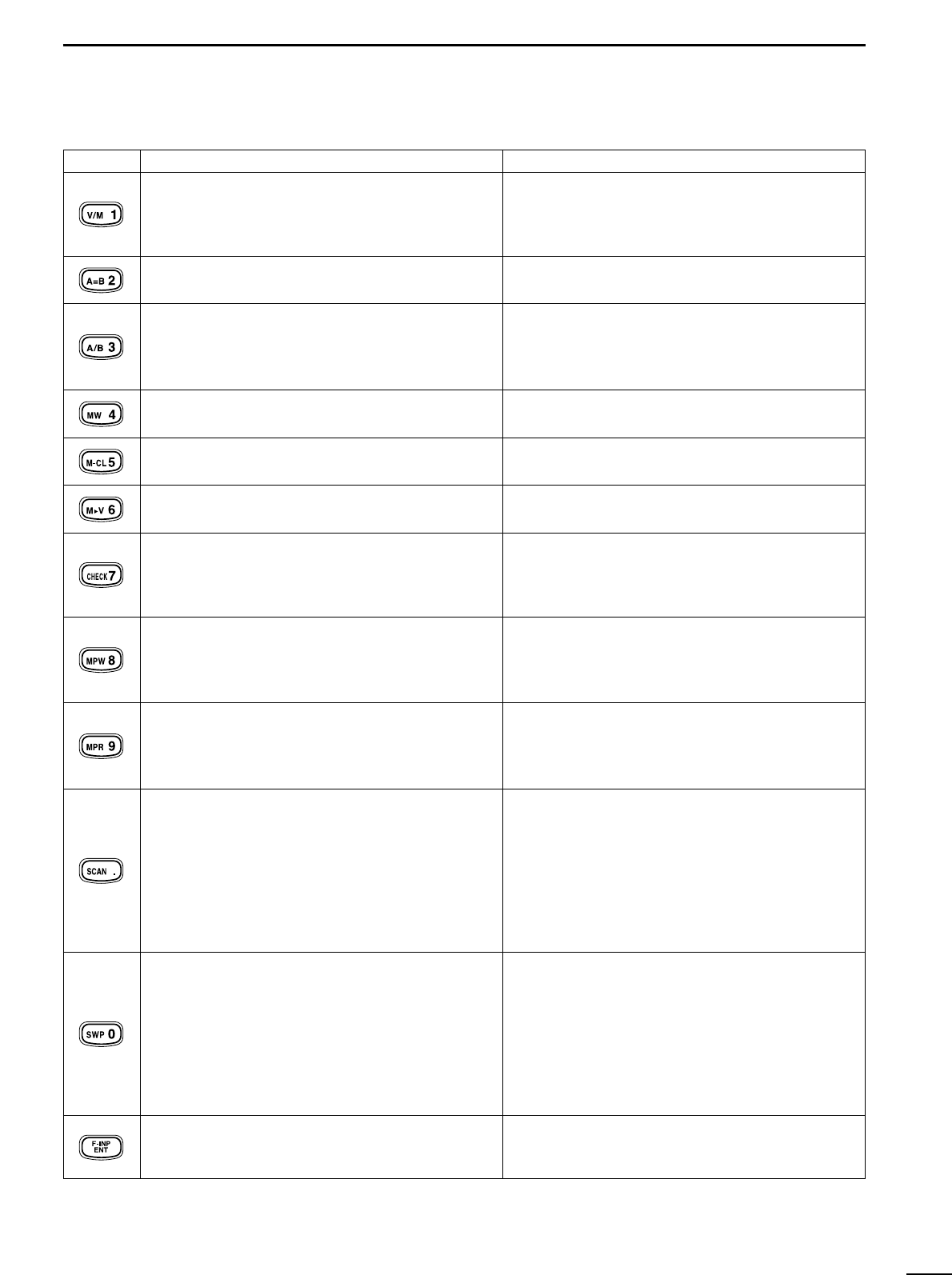
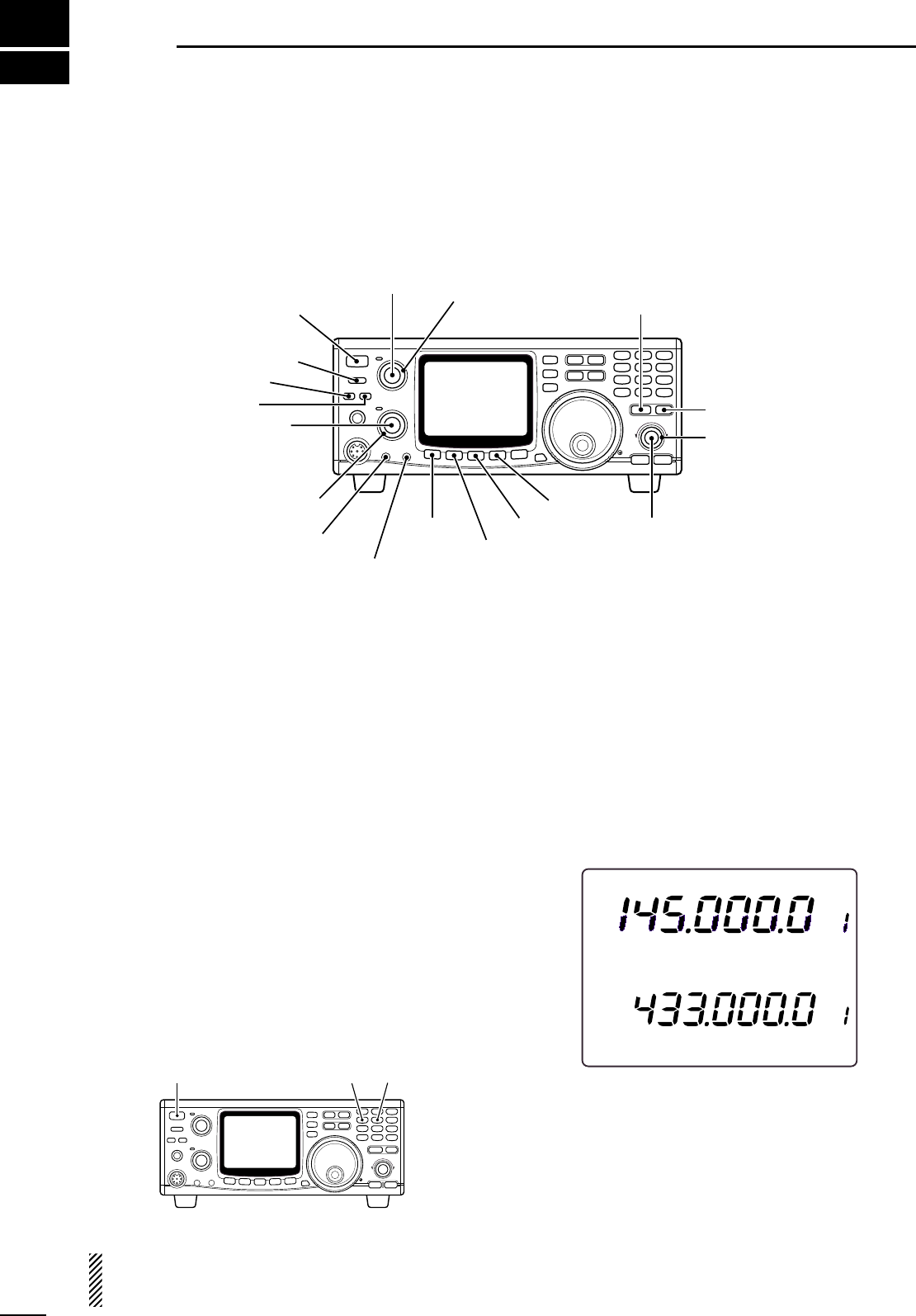
■ Front panel ..................................... 2
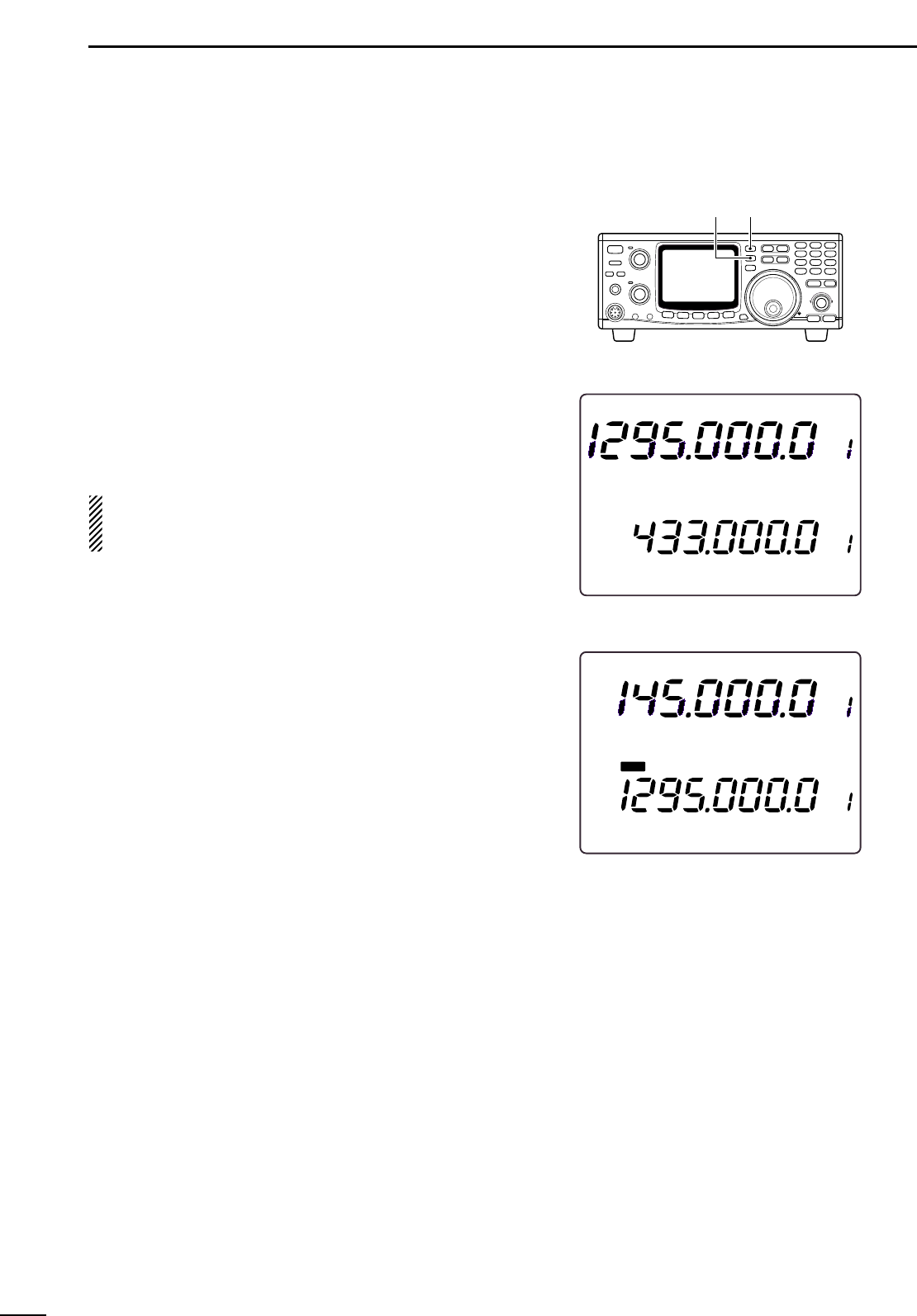
■ Function display ........................... 10
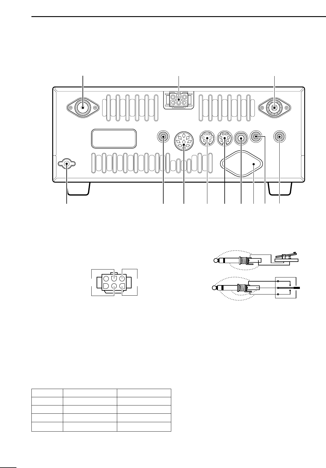
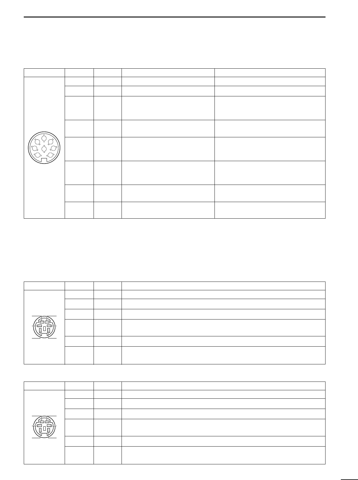
■ Rear panel .................................... 12
3 INSTALLATION AND
CONNECTIONS ................... 14– 17
■ Unpacking .................................... 14
■ Grounding ..................................... 14
■ Selecting a location ...................... 14
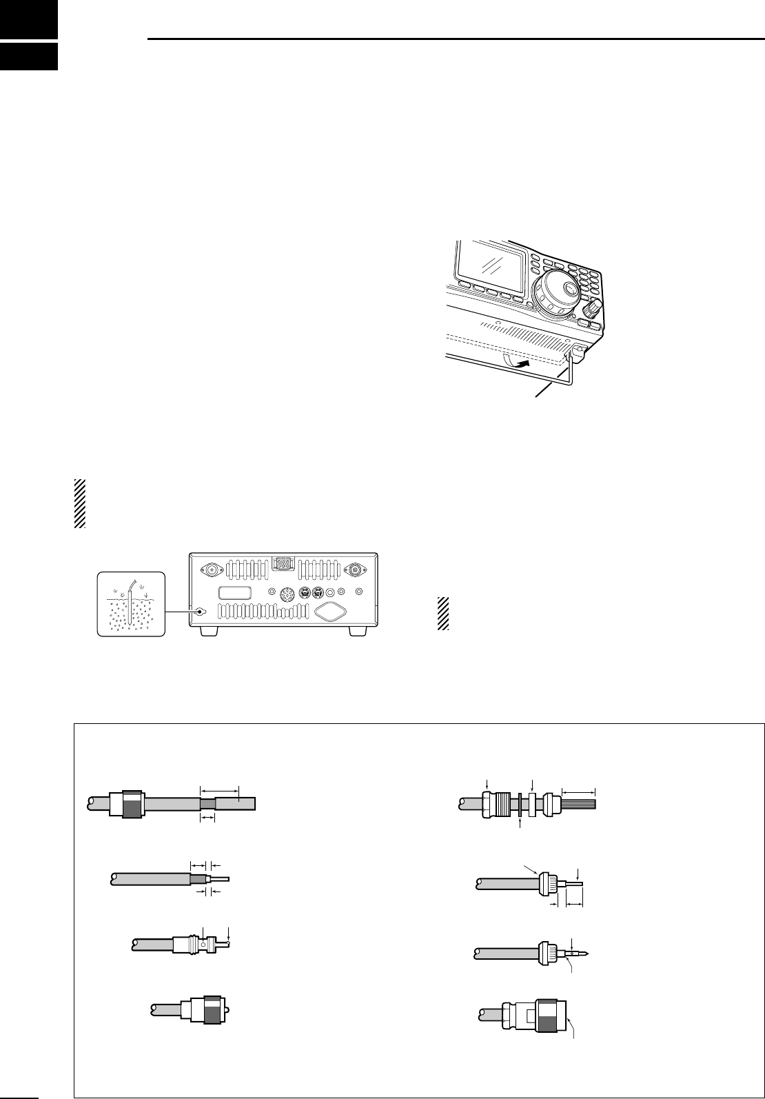
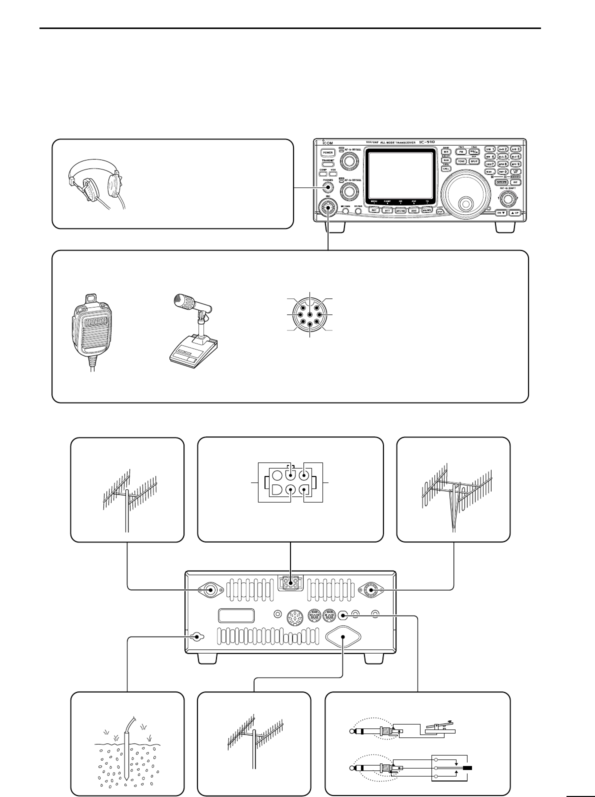
■ Antenna connection ...................... 14
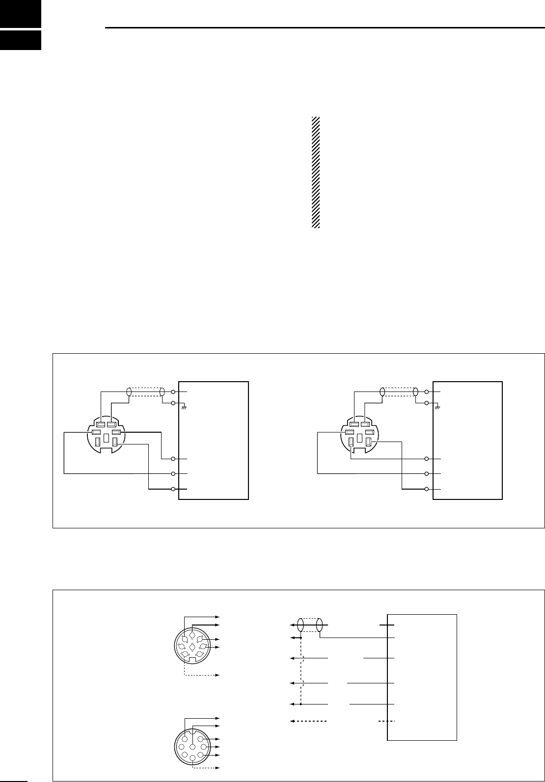
■ Required connections ................... 15
■ Advanced connections ................. 16
■ Power supply connections ............ 17
4 BASIC OPERATION ............. 18 – 25
■ Initial settings ................................ 18
■ When first applying power
(CPU resetting) ............................. 18
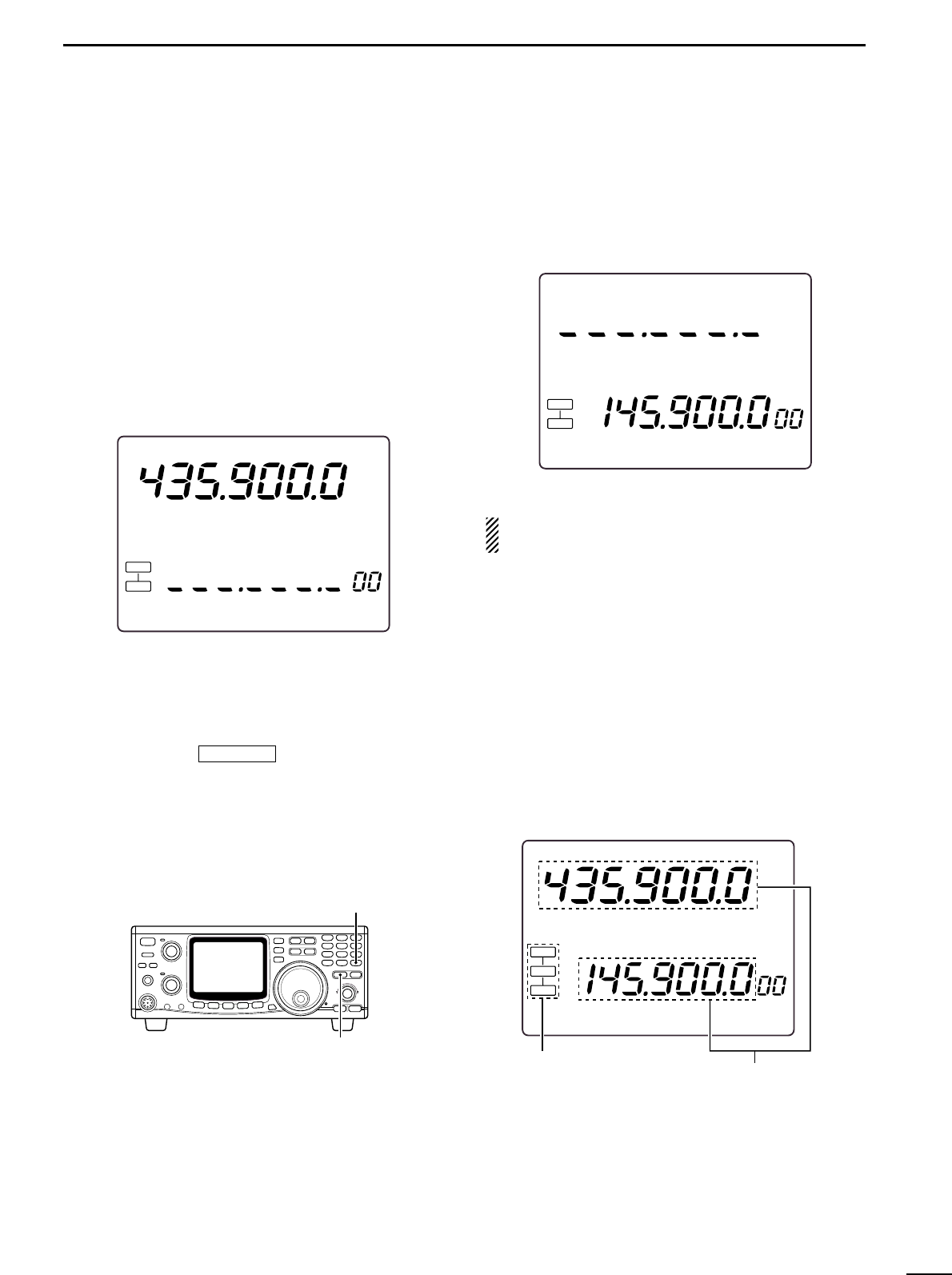
■ MAIN and SUB bands .................. 19
■ Operating band selection ............. 20
■ VFO description ............................ 21
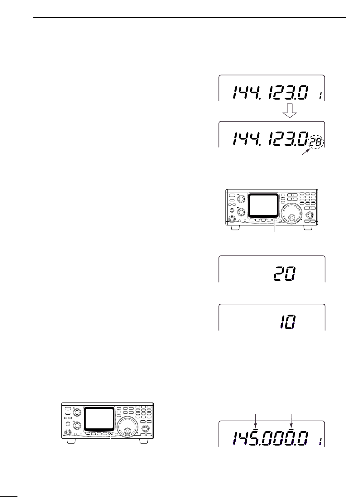
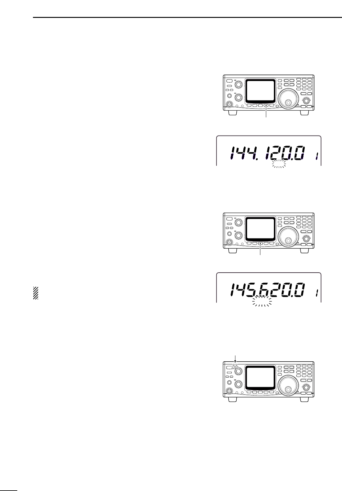
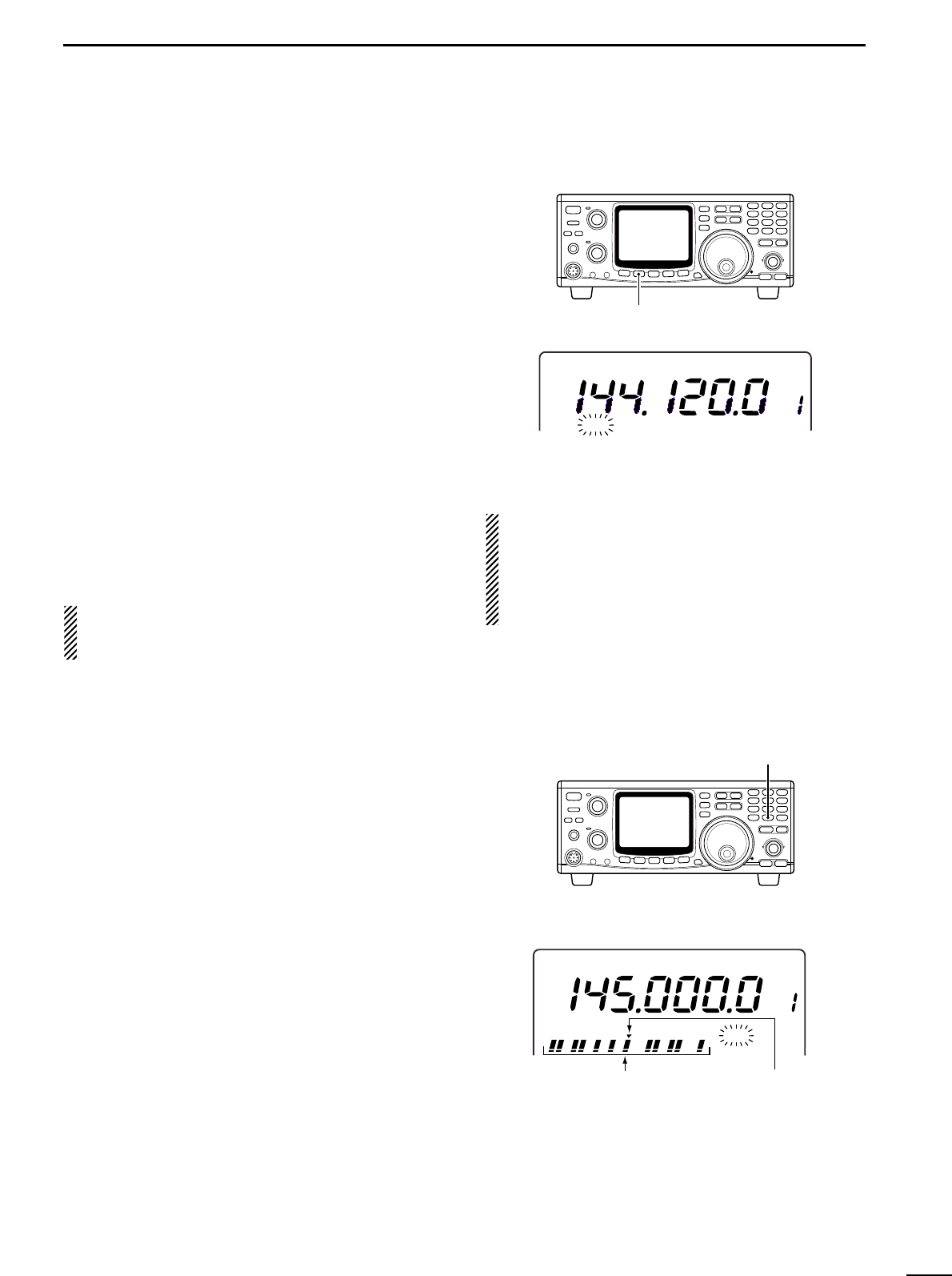
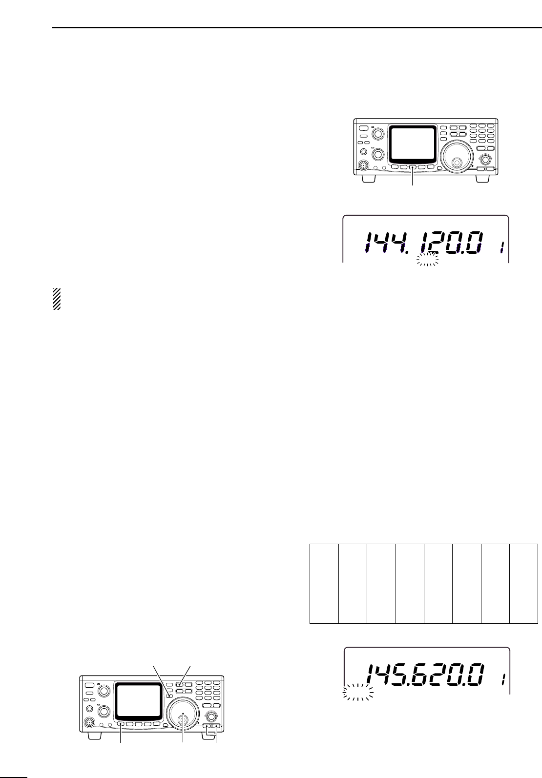
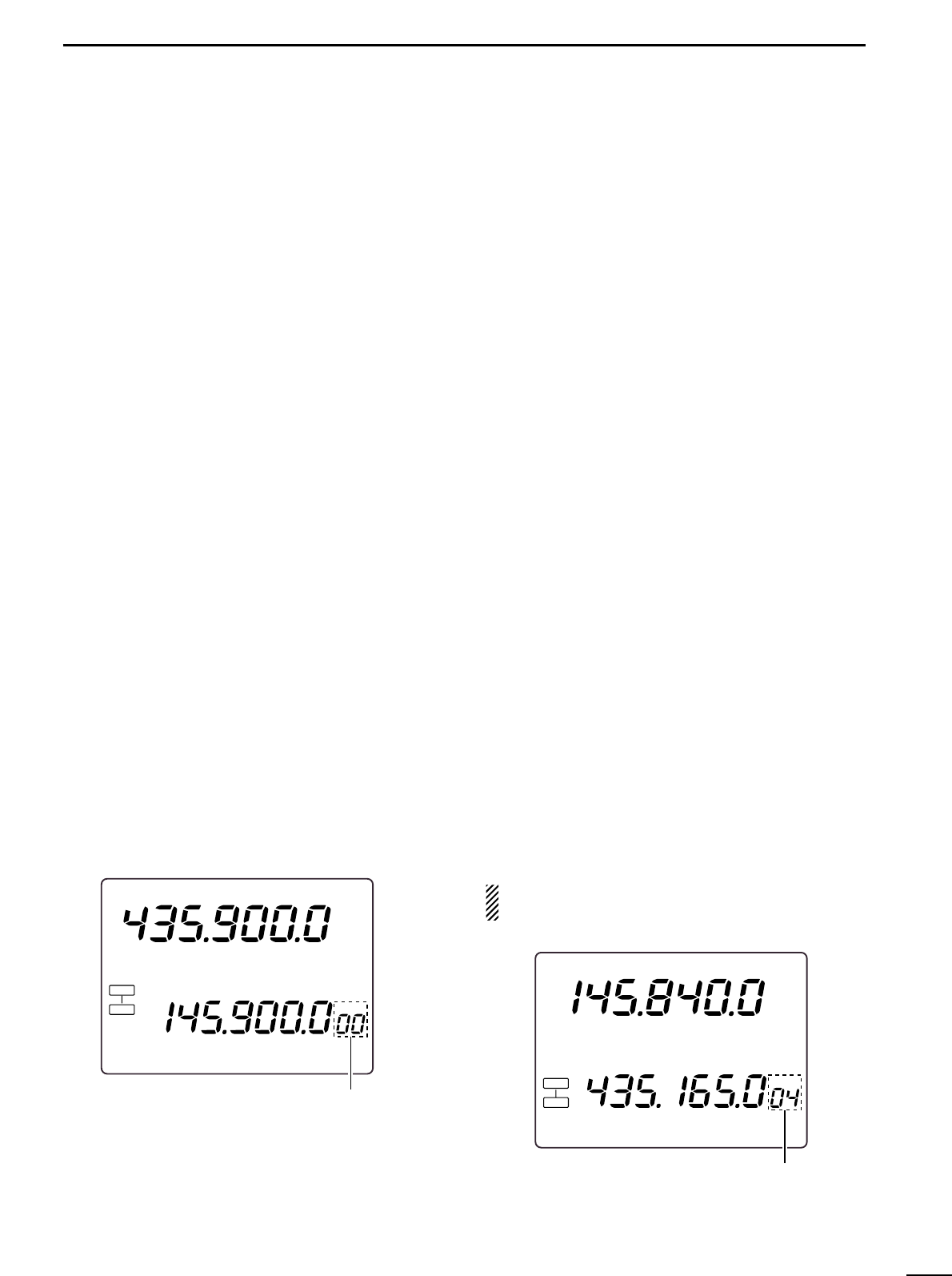
■ Frequency setting ......................... 22
■ SUB band OFF ............................. 24
■ SUB tuning dial ............................. 24
■ Dial lock function .......................... 25
5 RECEIVE AND TRANSMIT .. 26 –39
■ Functions for receive .................... 26
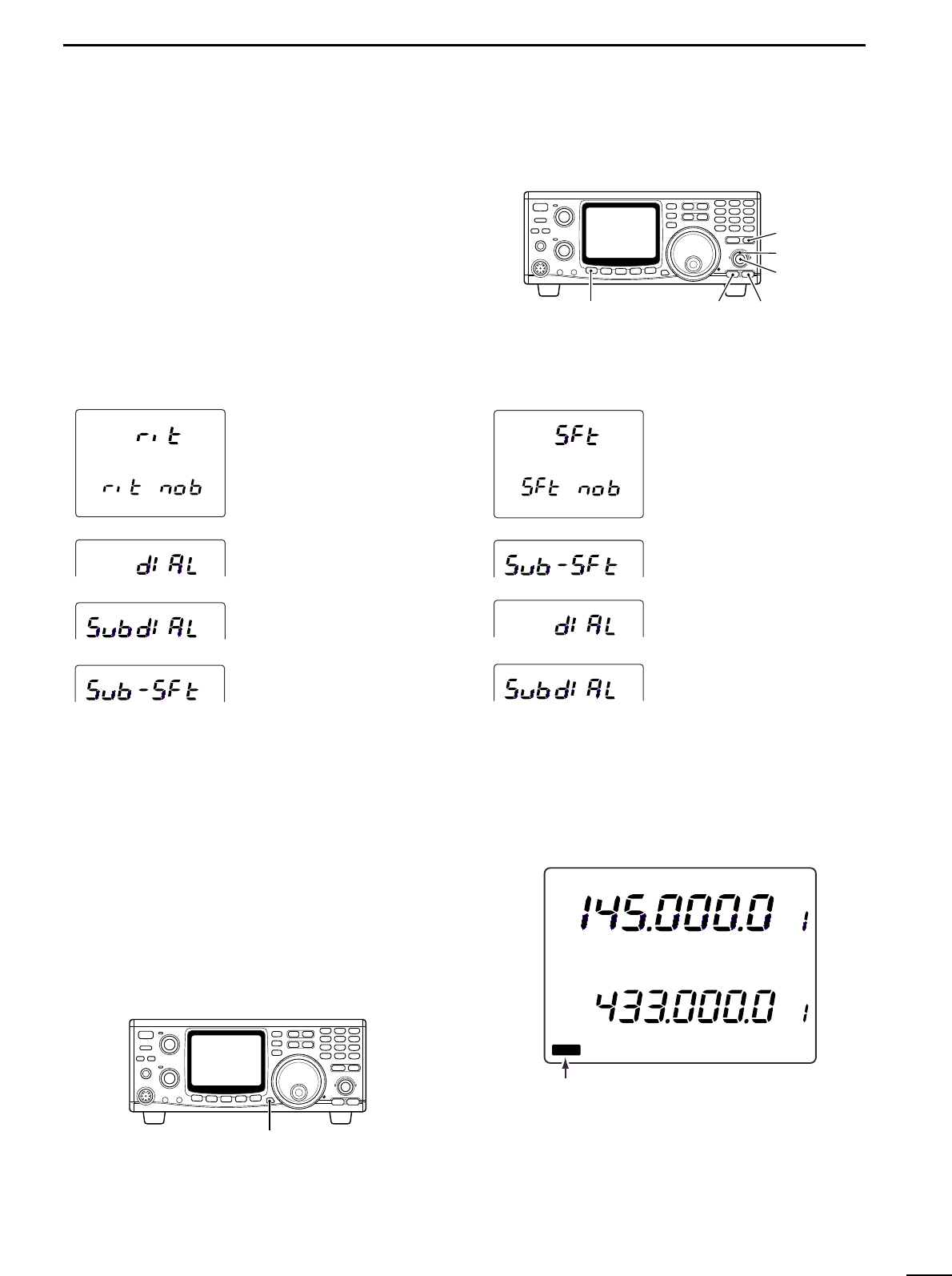
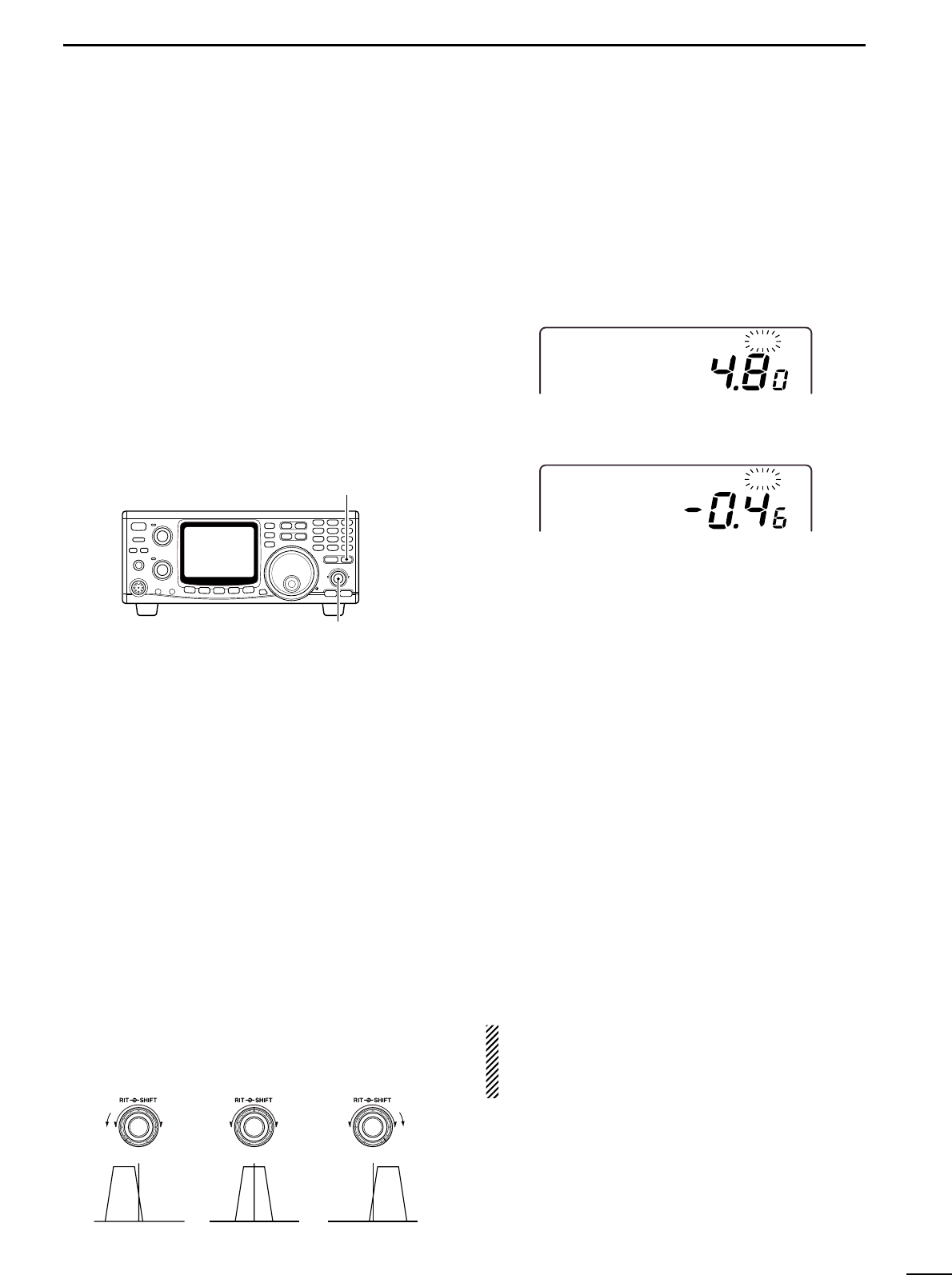
■ RIT function .................................. 27
■ IF shift function ............................. 27
■ AGC time constant ....................... 28
■ AFC function ................................. 28
■ FM center indicator ....................... 28
■ Attenuator ..................................... 29
■ Simple band scope ....................... 29
■ Noise blanker ............................... 30
■ Tone squelch operation ................ 30
■ Optional DSP functions ................ 31
■ Functions for transmit ................... 32
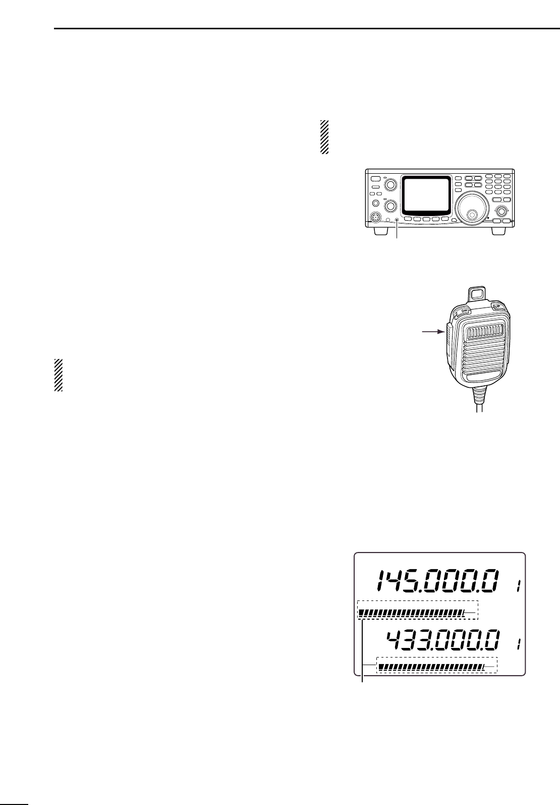
■ Transmit via microphone .............. 32
■ Indications during transmit ........... 32
■ FM mode operation ...................... 33
■ VOX operation .............................. 33
■ Repeater operation ....................... 34
■ SSB mode operation .................... 36
■ Speech compressor ..................... 36
■ Split frequency operation .............. 37
■ Full duplex operation .................... 37
■ Connections for CW ..................... 38
■ CW mode operation ..................... 38
6 MEMORY OPERATION ........ 40– 44
■ Memory channels ......................... 40
■ Operation on a memory channel .. 40
■ Programming in VFO mode .......... 41
■ Programming in memory mode .... 41
■ Blank channels ............................. 42
■ Frequency transferring ................. 42
■ Memory clearing ........................... 43
■ Call channels ................................ 43
■ Memo pads ................................... 44
7 SCANS ................................. 45– 47
■ Scan types .................................... 45
■ Preparation ................................... 45
■ Programmed scan operation ........ 46
■ Memory scan operation ................ 46
■ Memory select scan ..................... 47
■ Tone scan ..................................... 47
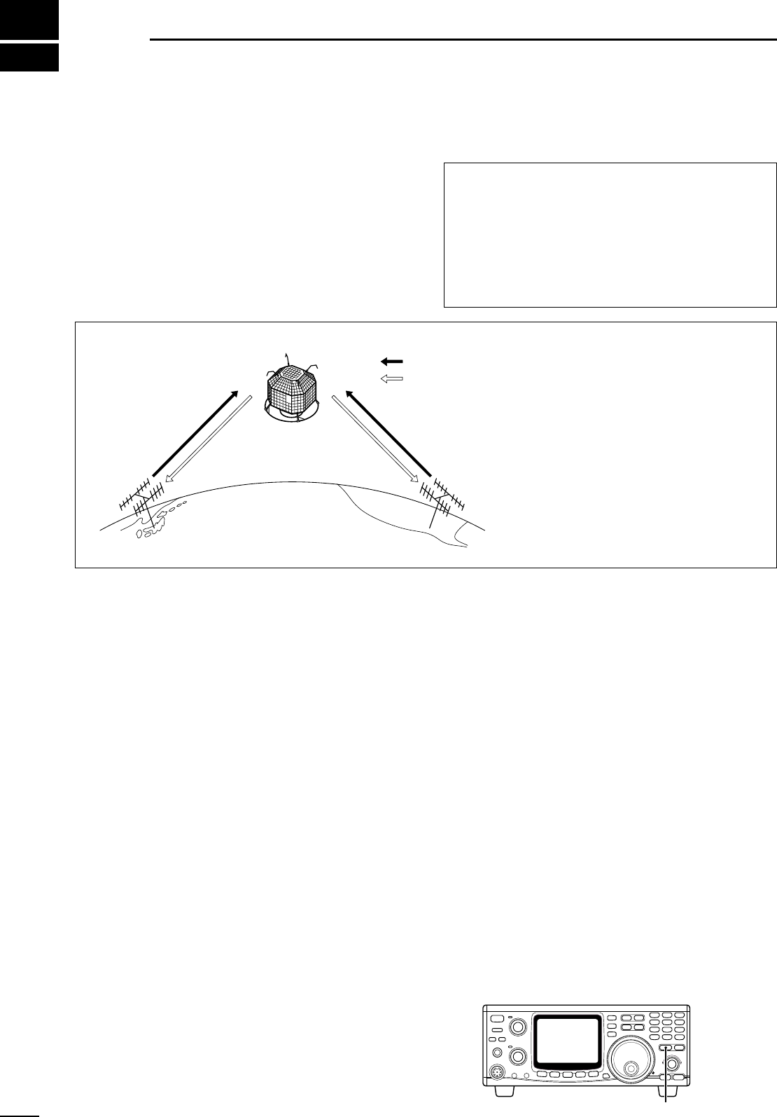
8 SATELLITE OPERATION ..... 48 –51
■ Satellite communications outline .. 48
■ Satellite notes ............................... 48
■ Entering into the satellite mode .... 48
■ Setting the satellite VFO ............... 49
■ Tracking selection ......................... 49
■ Preparation ................................... 50
■ Satellite operation ......................... 51
■ Satellite memory ........................... 51
9 DATA COMMUNICATION ..... 52– 54
■ Functions for AFSK ...................... 52
■ Connections for AFSK .................. 52
■ Operating mode notes .................. 53
■ Operating frequency notes ........... 53
■ AFSK operation ............................ 53
■ Setting the ACC socket ................ 54
10 SET MODE ........................... 55– 69
■ Set mode description .................... 55
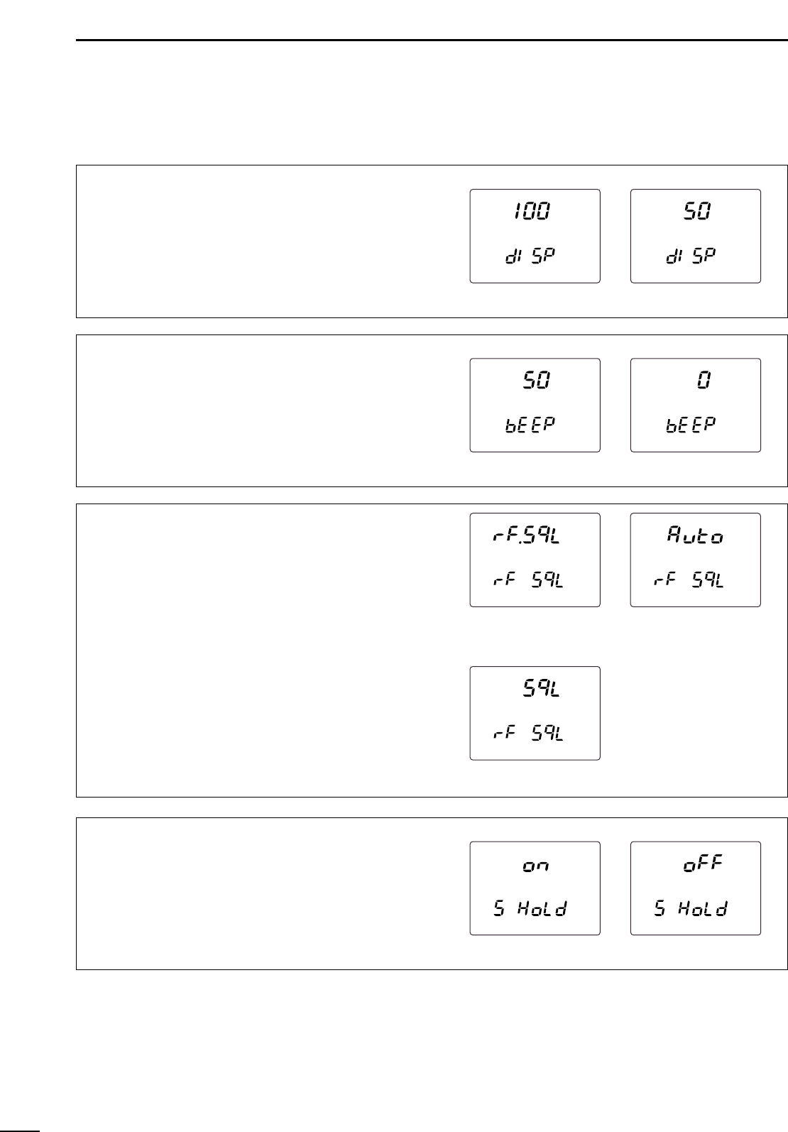
■ General set mode ......................... 56
■ FM set mode ................................ 60
■ SSB/CW set mode ....................... 62
■ Scan set mode ............................. 64
■ Memo pad set mode ..................... 64
■ Compressor set mode .................. 64
■ VOX set mode .............................. 65
■ Attenuator set mode ..................... 65
■ Transmit set mode ........................ 66
■ NR set mode ................................ 67
■ SWP set mode ............................. 67
■ RIT/SHIFT set mode .................... 68
■ Speech set mode ......................... 69
11 OPTION INSTALLATIONS ... 70– 76
■ Internal view ................................. 70
■ Opening the transceiver’s case .... 71
■ UT-102
VOICE SYNTHESIZER
UNIT
.............................................. 71
■ UT-106 DSP UNIT .......................... 72
■ UX-910 1200 MHz BAND UNIT
........ 73
■ CR-293
HIGH STABILITY CRYSTAL
UNIT
.............................................. 74
■ FL-132/FL-133
CW NARROW
FILTER
........................................... 75
12 MAINTENANCE ................... 76– 77
■ Troubleshooting ............................ 76
■ Fuse replacement ......................... 77
■ CPU resetting ............................... 77
13 CONTROL COMMAND ........ 78 – 79
■ Remote jack (CI-V) information .... 78
14 SPECIFICATIONS ....................... 80
15 OPTIONS ..................................... 81
16 INSTALLATION NOTES ....... 82– 83