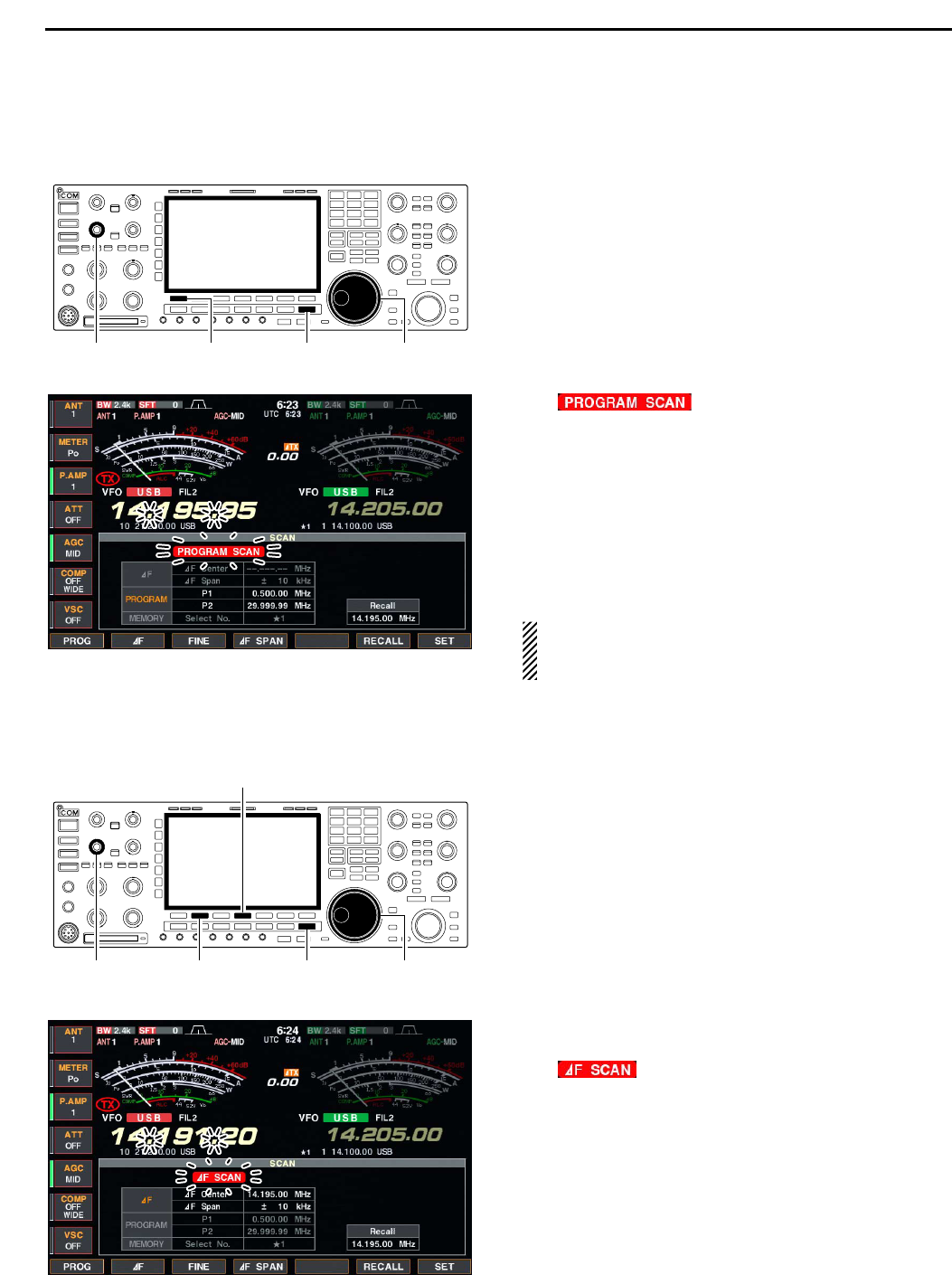
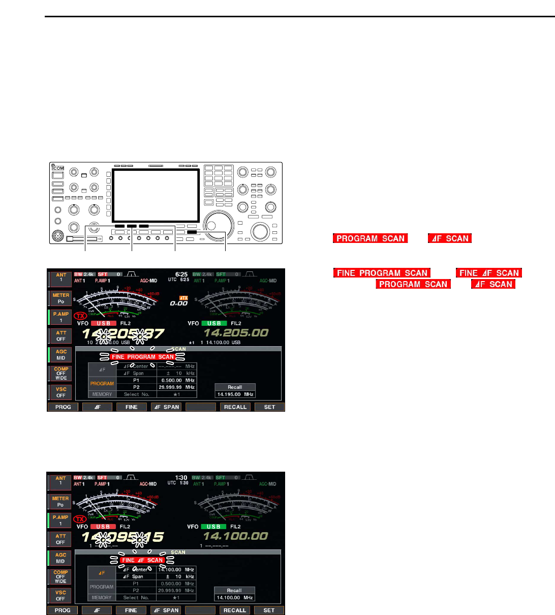
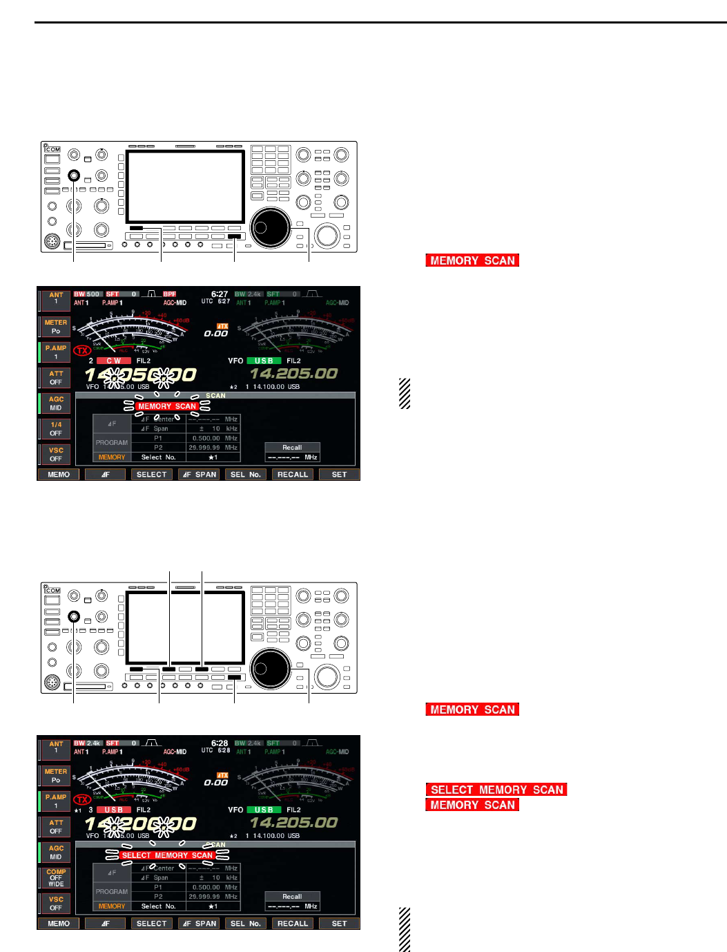
14-5
DD
Command table (continued)
14
CONTROL COMMAND
Command Sub command Description
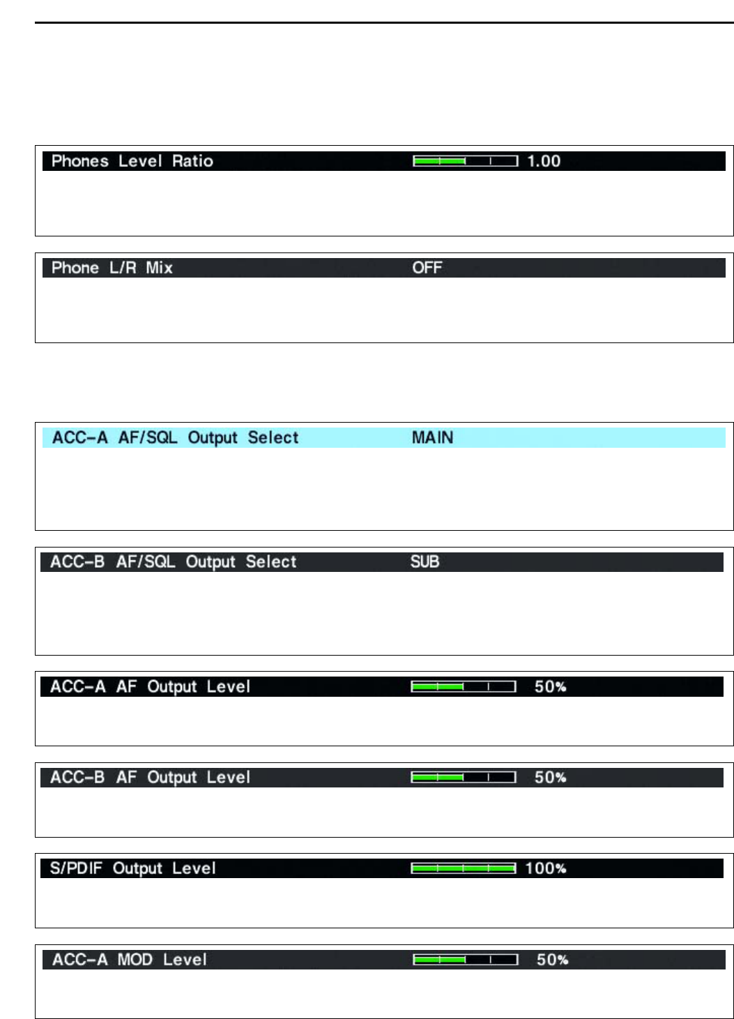
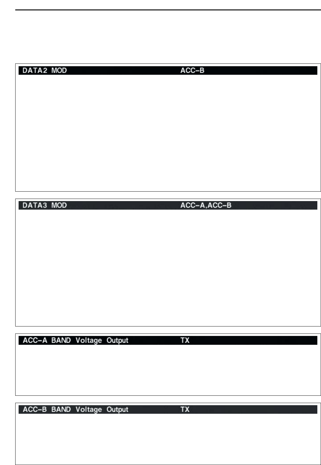
1A 050035 Send/read the band selection for
operating frequency band signal
output to ACC-A. (0=MAIN,
1=SUB, 2=TX)
050036 Send/read the band selection for
operating frequency band signal
output to ACC-A. (0=MAIN,
1=SUB, 2=TX)
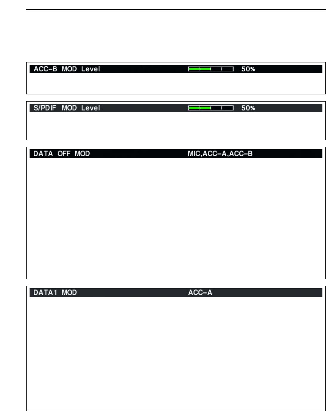
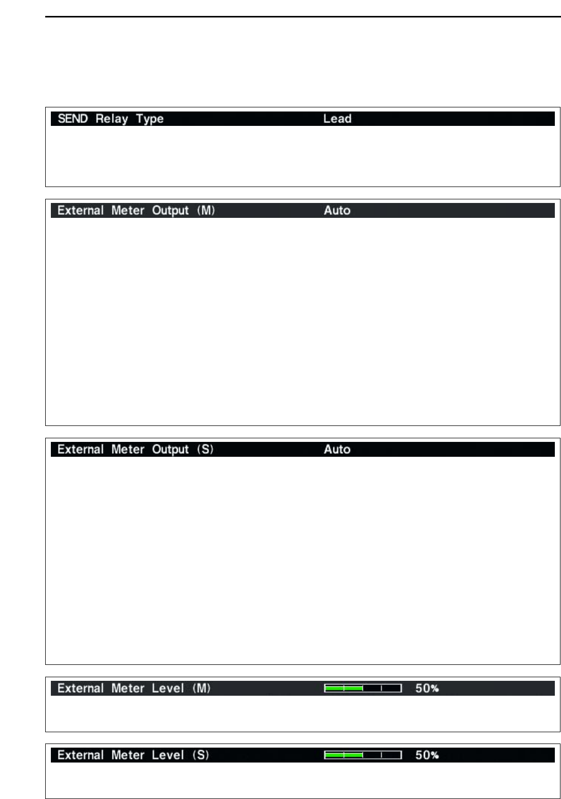
050037 Send/read relay type selection
(0=Lead, 1=MOS-FET)
050038 Send/read main band’s external
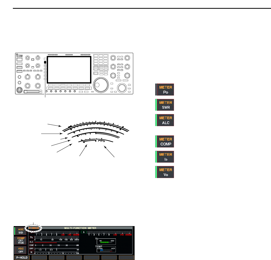
meter output selection (0=Auto,
1=S (main), 2=Po, 3=SWR,
4=ALC, 5=COMP, 6=V
D, 7=ID)
050039 Send/read sub band’s external
meter output selection (0=Auto,
1=S (sub), 2=Po, 3=SWR,
4=ALC, 5=COMP, 6=V
D, 7=ID)
050040 Send/read main band’s external
meter output level
(0=0% to 255=100%)
050041 Send/read sub band’s external
meter output level
(0=0% to 255=100%)
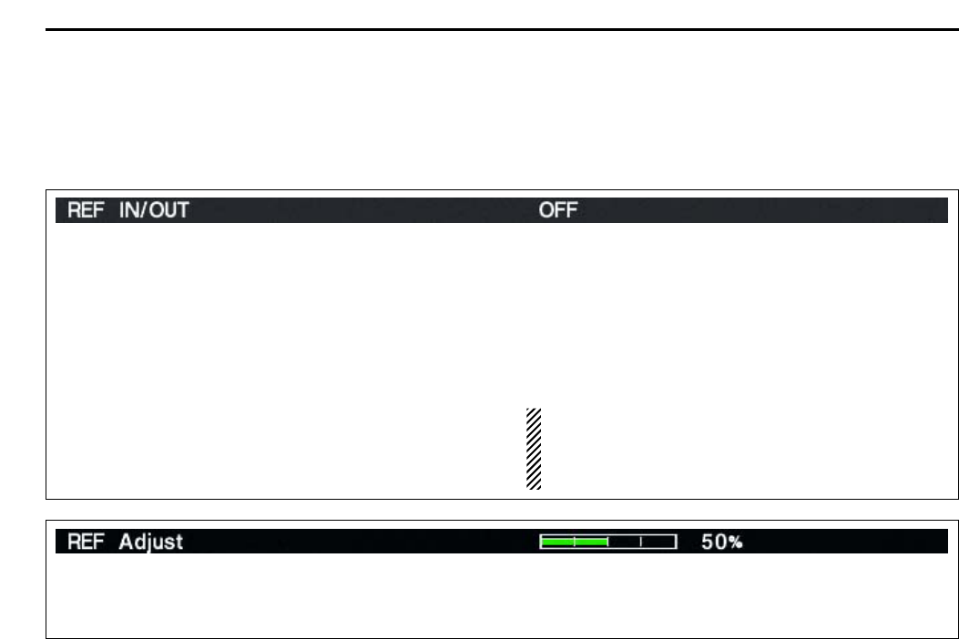
050042 Send/read reference signal in/out
setting (0=OFF, 1=IN, 2=OUT)
050043 Send/read reference signal fre-
quency setting
(0=0% to 255=100%)
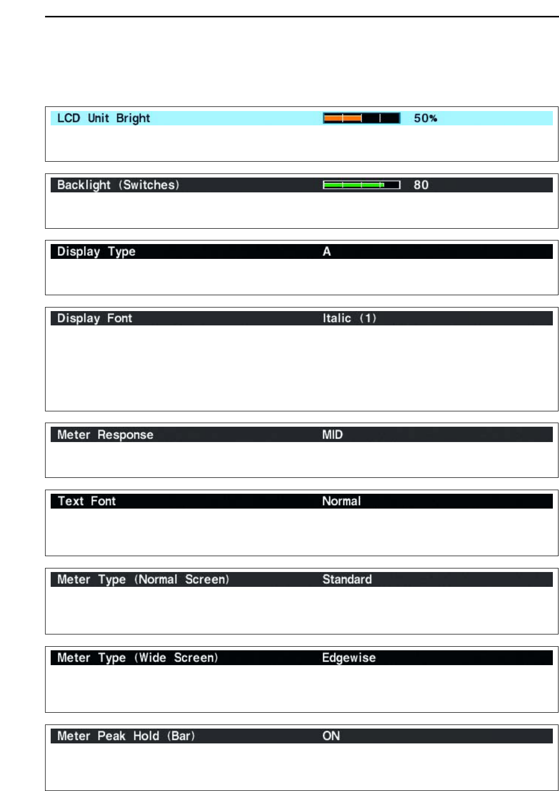
050044 Send/read LCD unit backlight
brightness (0=0% to 255=100%)
050045 Send/read switch indicator bright-
ness (0=0% to 255=100%)
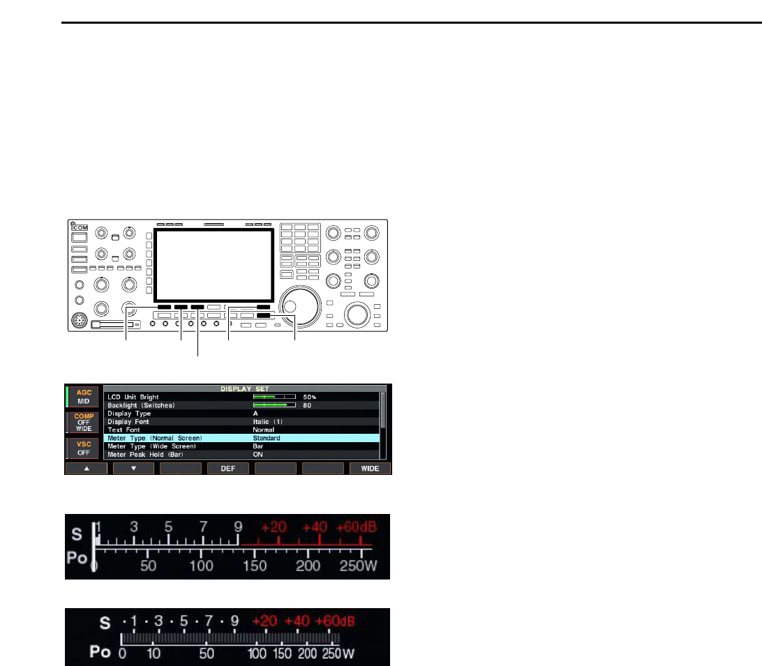
050046 Send/read screen image type
(0=A, 1=B, 2=C)
050047 Send/read frequency readout font
(
0=Italic (1), 1=Italic (2), 2=Italic (3),
3=Italic (4), 4=Round (1),
5=Round (2), 6=Round (3),
7=Shadow (1), 8=Shadow (2),
9=Shadow (3), 10=Qubic (1),
11=Qubic (2), 12=Qubic (3),
13=Qubic (4), 14=IC-780 (1),
15=IC-780 (2), 16=IC-780 (3),
17=IC-780 (4))
050048 Send/read font for other than fre-
quency readout
(0=Normal, 1=Slim)
050049 Send/read meter type
(0=Standard, 1=Edgewise, 2=Bar)
050050 Send/read meter type during wide
screen or mini scope indication
(0=Edgewise, 1=Bar)
050051 Send/read peak hold set
(0=OFF, 1=ON)
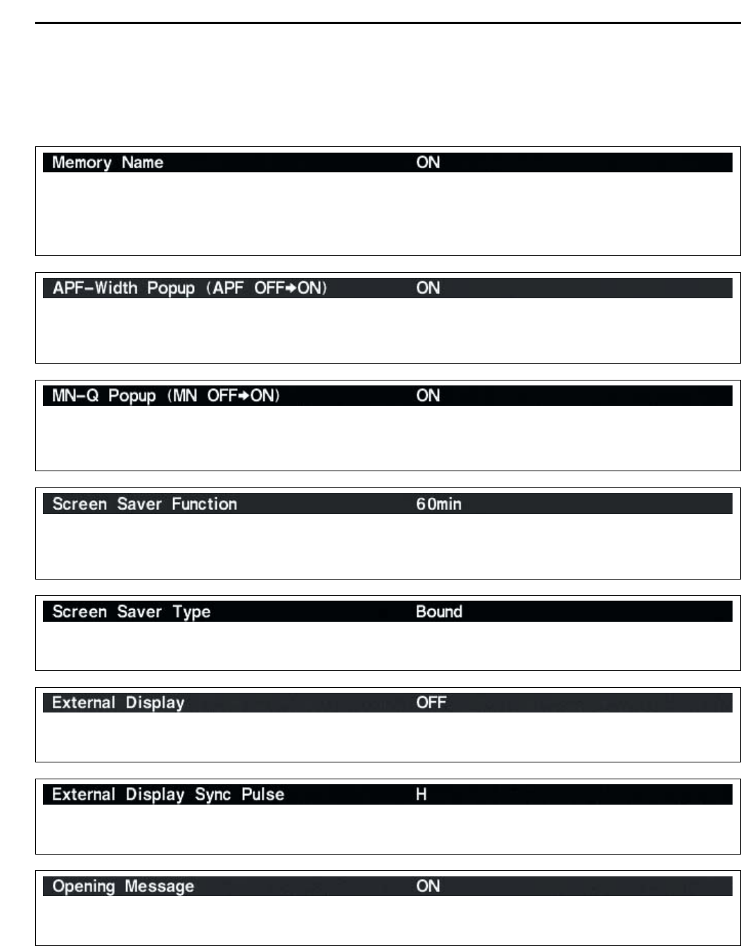
050052 Send/read memory name indica-
tion setting (0=OFF, 1=ON)
050053 Send/read audio peak filter width
pop-up indication setting
(0=OFF, 1=ON)
050054 Send/read manual notch width
pop-up indication setting
(0=OFF, 1=ON)
050055 Send/read output signal setting for
external display (0=OFF, 1=ON)
050056 Send/read synchronous pulse
level setting (0=L, 1=H)
Command Sub command Description
1A 050057 Send/read opening message indi-
cation (0=OFF, 1=ON)
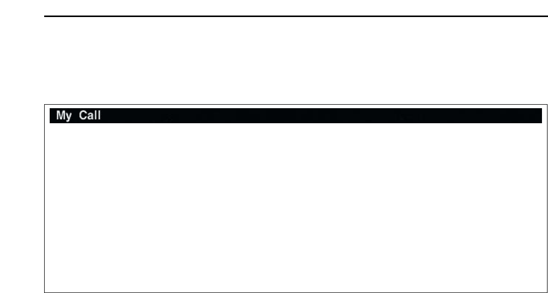
050058 Send/read opening message con-
tents (see p. 14-9 for details)
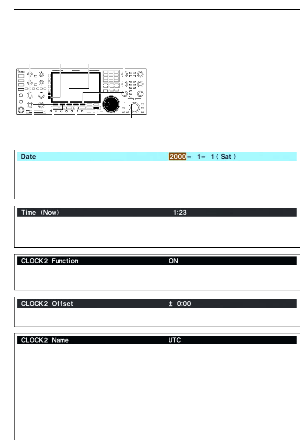
050059 Send/read date (20000101=1st
Jan. 2001 to 20991231=31st Dec.
2099)
050060 Send/read time (0000=00:00 to
2359=23:59)
050061 Send/read clock 2 function
(0=OFF, 1=ON)
050062 Send/read offset time for clock 2
(240001=–24:00 to 240000=+24:00)
050063 Send/read clock 2 name (up to 3-
character; see p. 14-9)
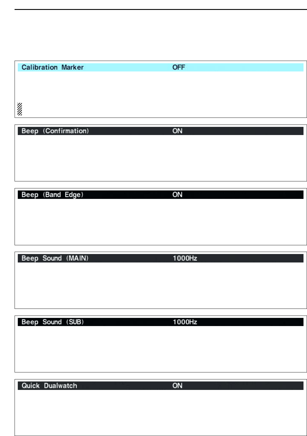
050064 Send/read calibration marker
(0=OFF, 1=ON)
050065 Send/read confirmation beep
(0=OFF, 1=ON)
050066 Send/read band edge beep
(0=OFF, 1=ON)
050067 Send/read main band’s beep
audio frequency
(50=500 Hz to 200=2000 Hz)
050068 Send/read sub band’s beep audio
frequency
(50=500 Hz to 200=2000 Hz)
050069 Send/read quick dualwatch func-
tion (0=OFF, 1=ON)
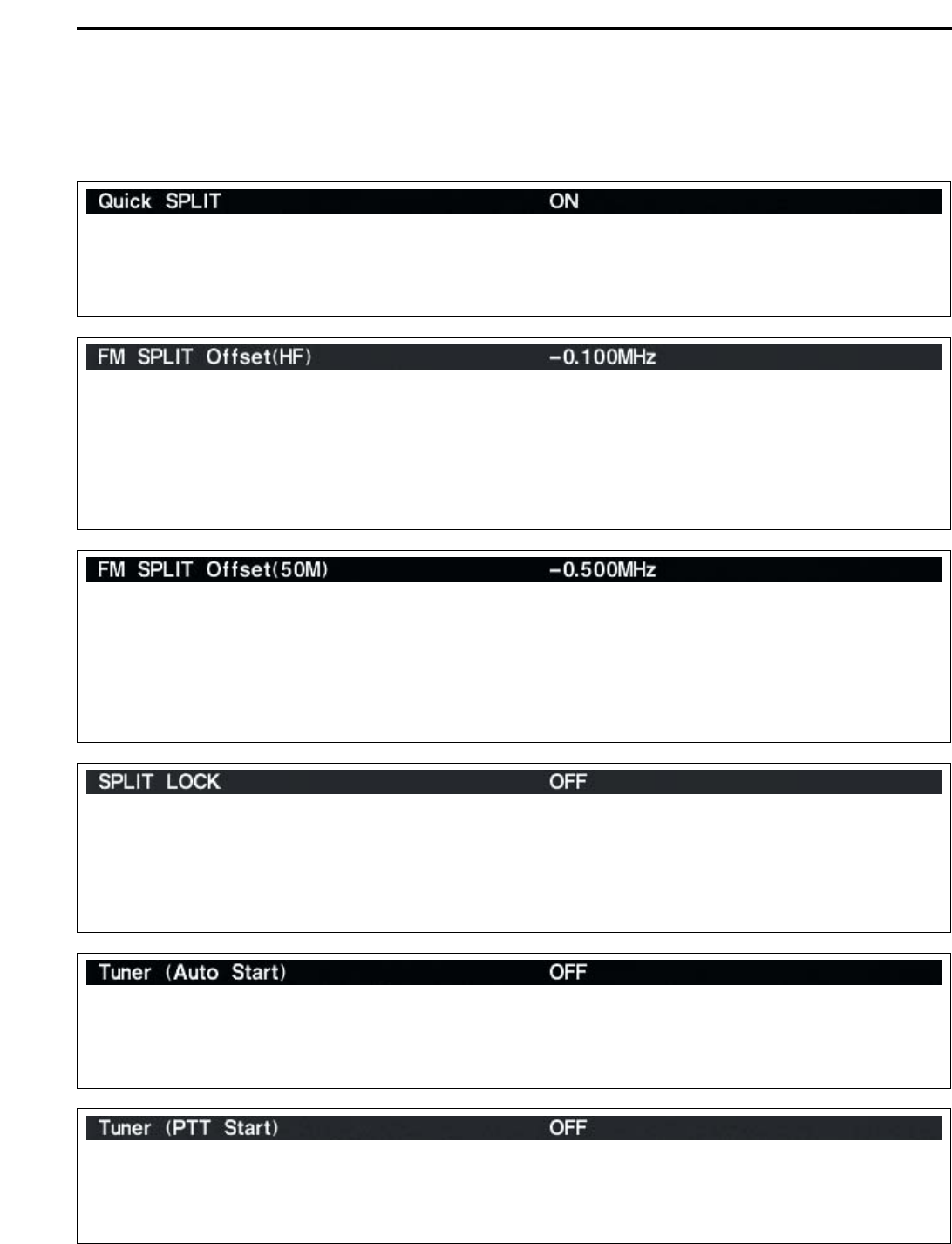
050070 Send/read quick split set (0=OFF,
1=ON)
050071 Send/read FM split offset –9.999
to +9.999 MHz for HF
(see p. 14-10 for details)
050072 Send/read FM split offset –9.999
to +9.999 MHz for 50 MHz
(see p. 14-10 for details)
050073 Send/read split lock set (0=OFF,
1=ON)
050074 Send/read tuner auto start set
(0=OFF, 1=ON)
050075 Send/read PTT tune set (0=OFF,
1=ON)
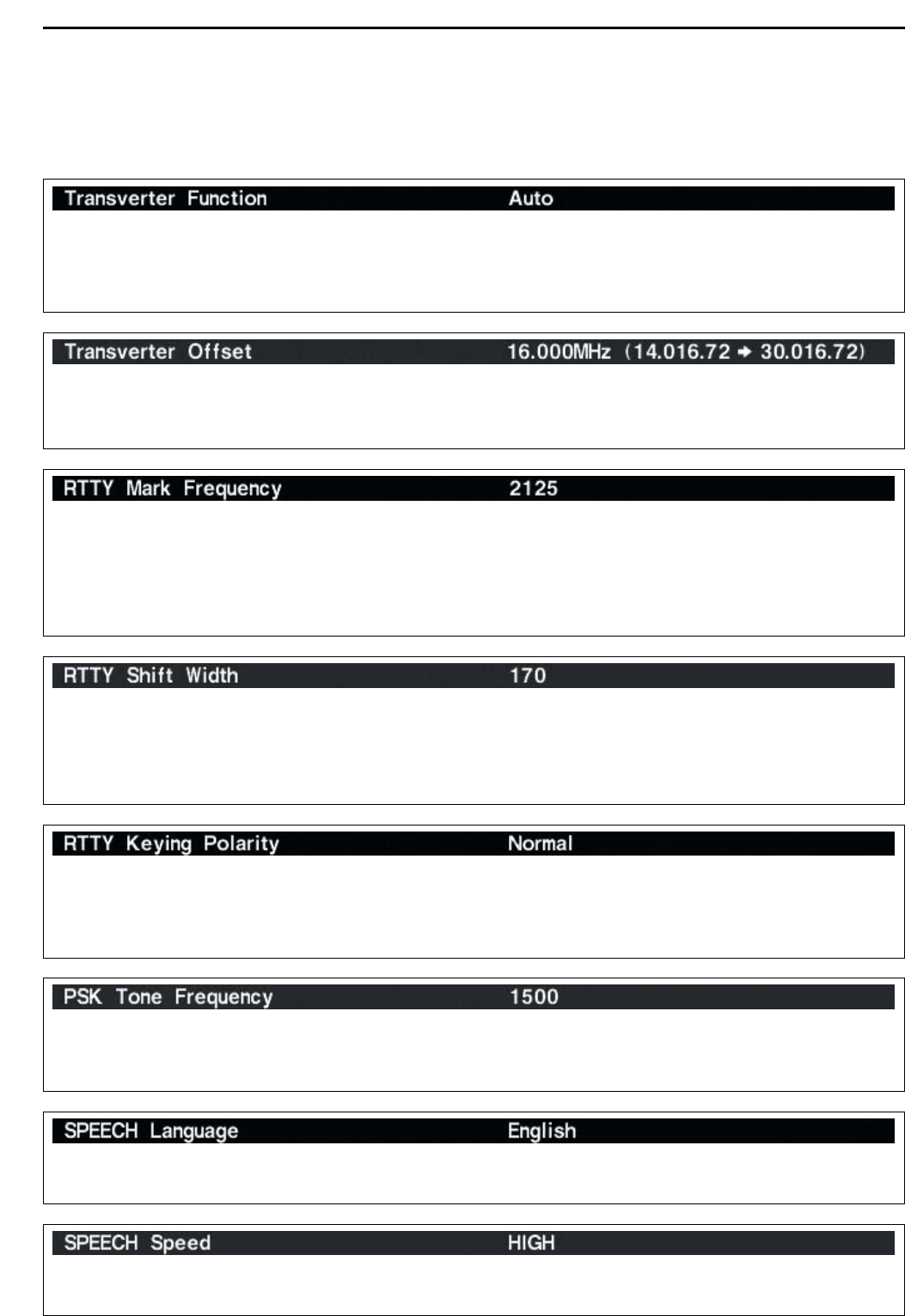
050076 Send/read transverter set
(0=OFF, 1=ON)
050077 Send/read transverter offset (see
p. 14-10 for details)
050078 Send/read RTTY mark frequency
(0=1275 Hz, 1=1615 Hz,
2=2125 Hz)
050079 Send/read RTTY shift width
(0=170 Hz, 1=200 Hz, 2=425 Hz)
050080 Send/read RTTY keying polarity
(0=Normal, 1=Reverse)
050081 Send/read PSK tone frequency
(0=1000 Hz, 1=1500 Hz,
2=2000 Hz)
050082 Send/read speech language
(0=English, 1=Japanese)
050083 Send/read speech speed (0=Slow,
1=Fast)
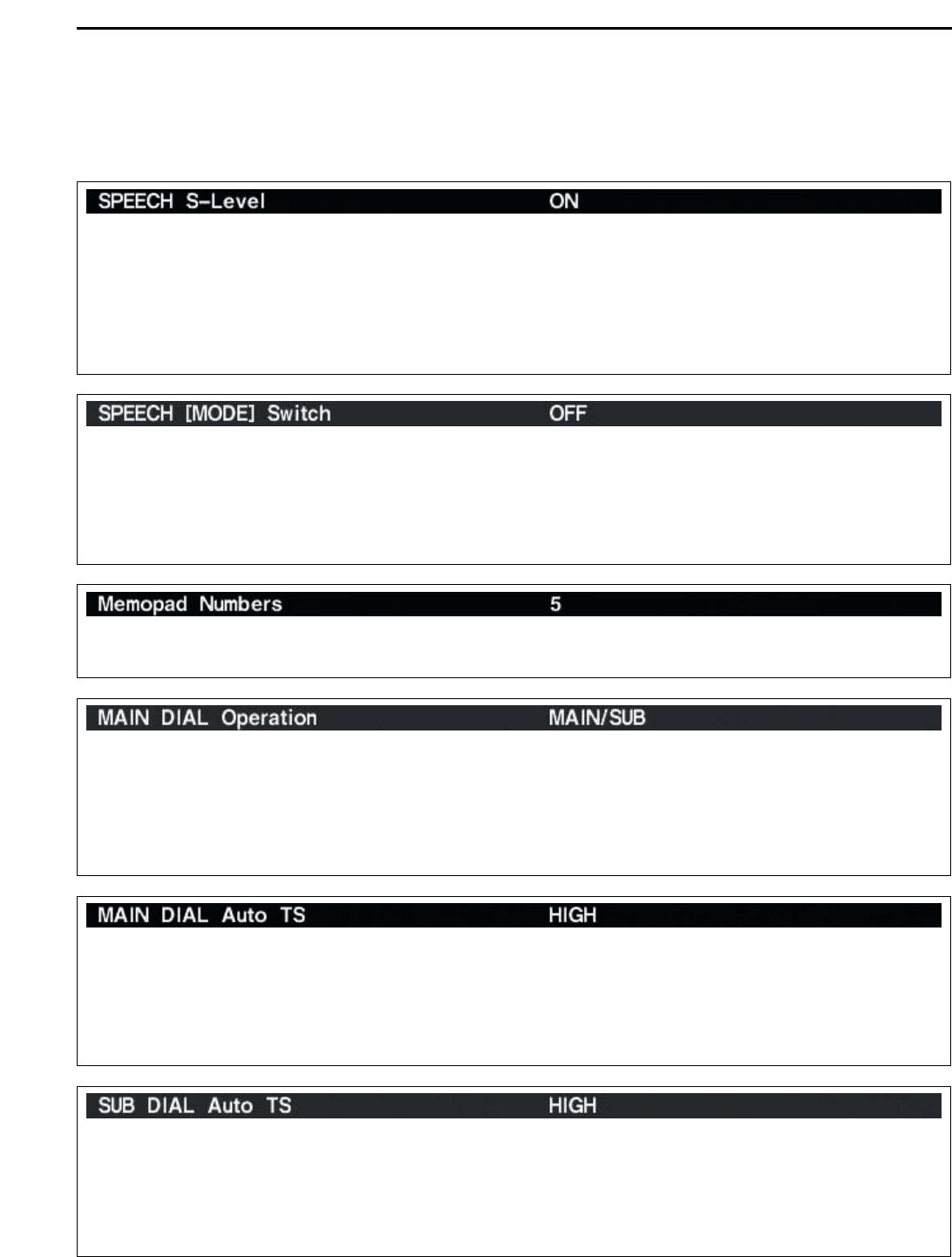
050084 Send/read S-level speech
(0=OFF, 1=ON)
050085 Send/read speech with a mode
switch operation (0=OFF, 1=ON)
050086 Send/read memo pad numbers
(0=5 ch, 1=10 ch)