IMPORTANT .............................................................. i
EXPLICIT DEFINITIONS ........................................... i
PRECAUTIONS ........................................................ i
1 TABLE OF CONTENTS ....................................... 1
SUPPLIED ACCESSORIES ..................................... 1
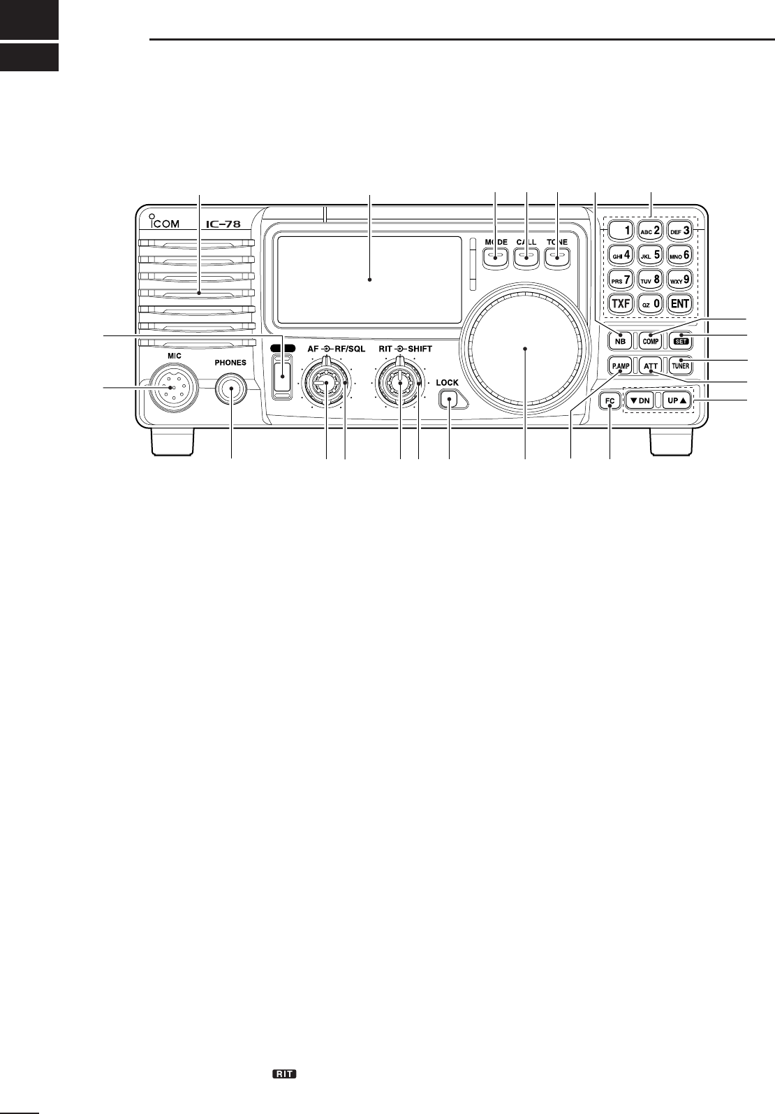
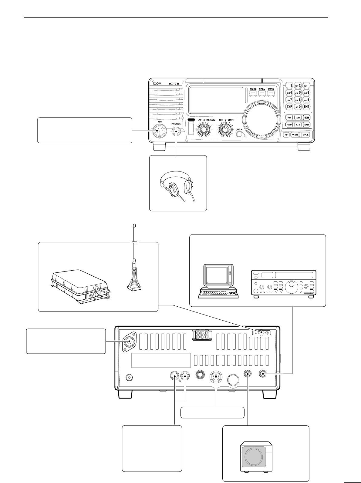
2 PANEL DESCRIPTION ................................... 2–7
■ Front panel ....................................................... 2
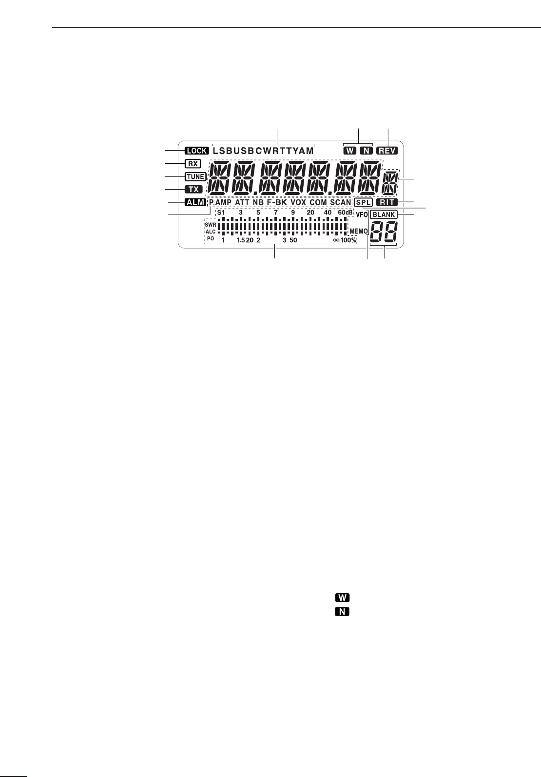
■ Function display ............................................... 4
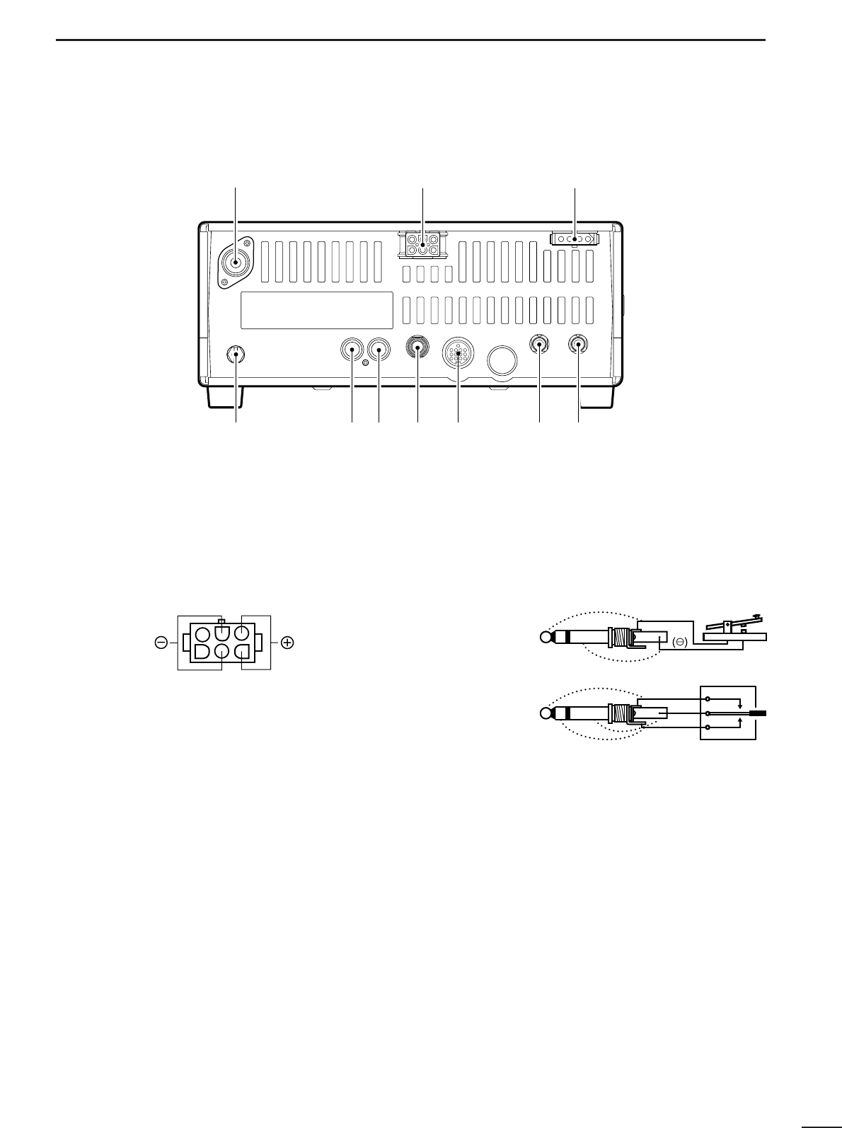
■ Rear panel ........................................................ 5
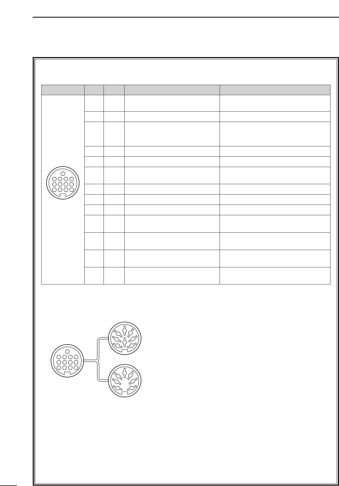
■ Microphone (HM-36) ........................................ 7
3 INSTALLATION AND CONNECTIONS ......... 8–12
■ Unpacking ........................................................ 8
■ Selecting a location .......................................... 8
■ Grounding ......................................................... 8
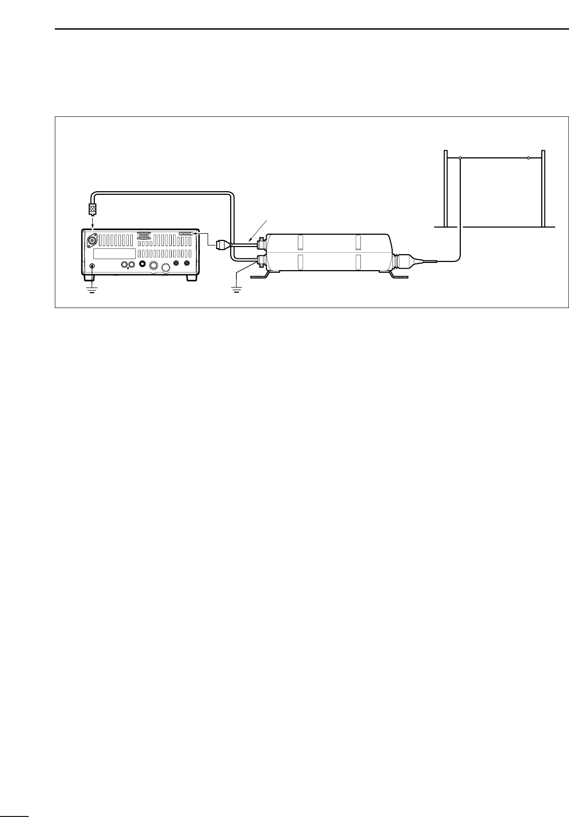
■ Antenna connection .......................................... 8
■ Required connections ....................................... 9
■ Power supply connections .............................. 10
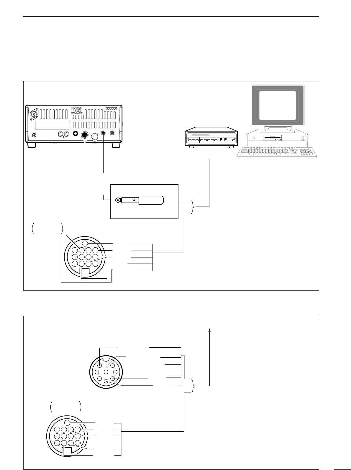
■ Advanced connections .................................... 11
■ External antenna tuners ................................. 12
4 OPERATION................................................. 13–27
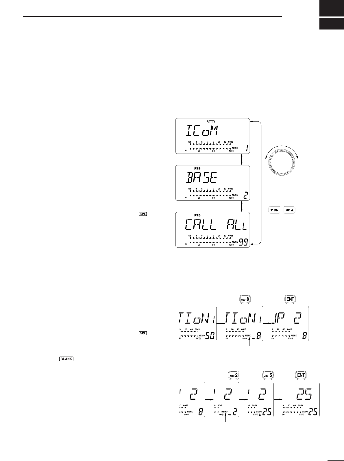
■ Selecting a channel......................................... 13
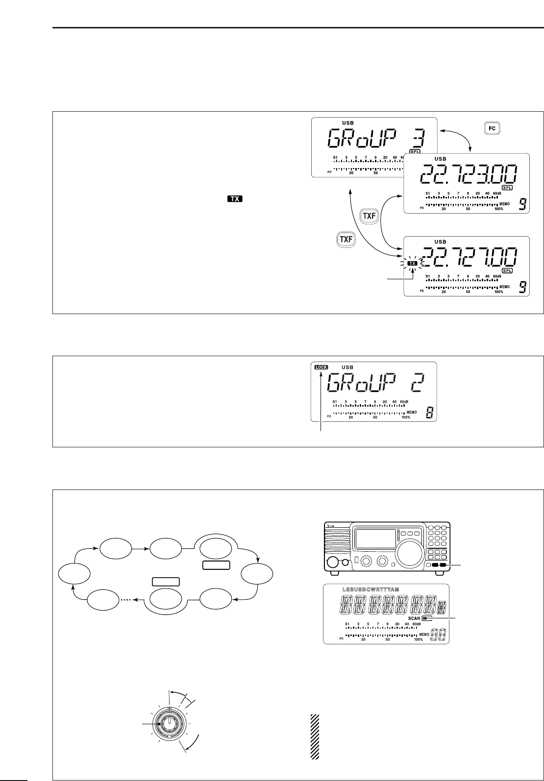
■ Frequency indication ....................................... 14
■ Lock function................................................... 14
■ Scan function................................................... 14
■ Basic voice receive and transmit..................... 15
■ Mode selection................................................ 15
■ RF gain and Squelch....................................... 15
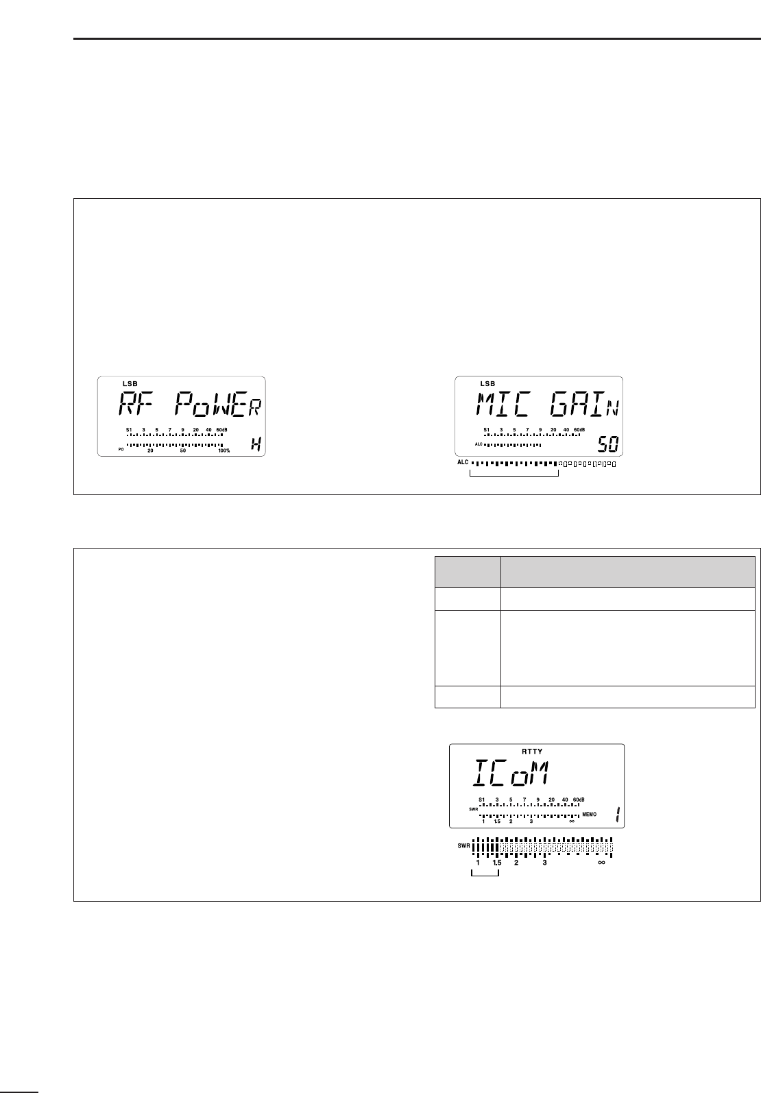
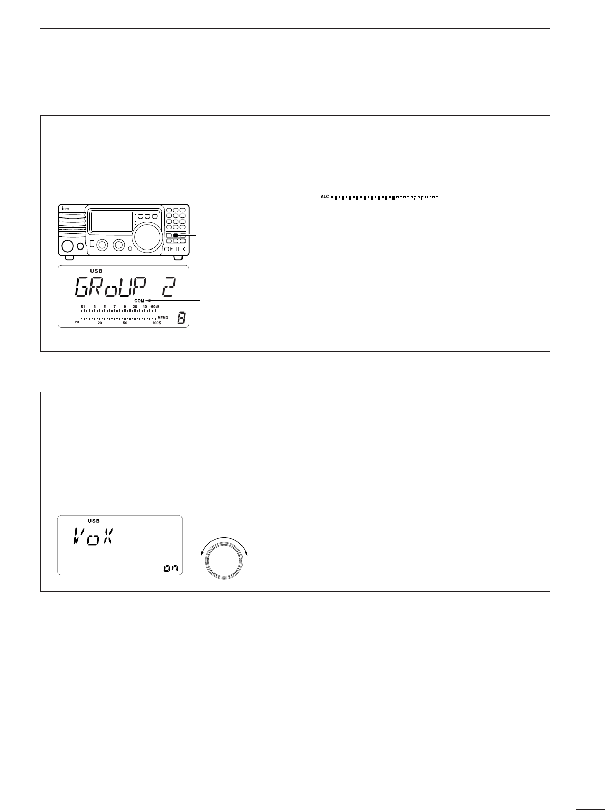
■ Functions for transmit...................................... 16
■ Functions for receive....................................... 19
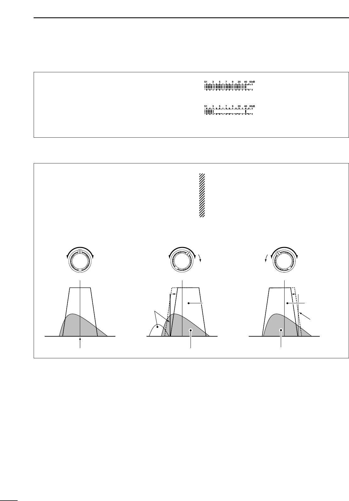
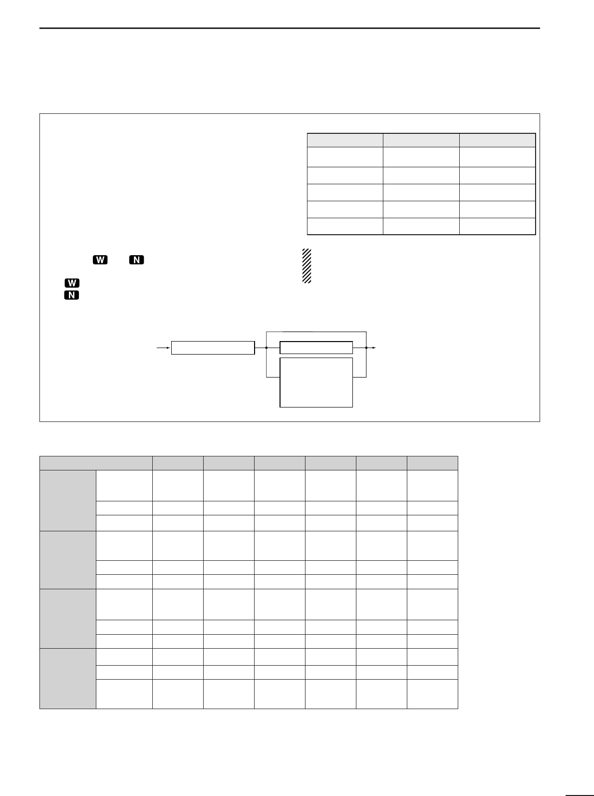
■ Filter selection ................................................. 21
■ Filter setting..................................................... 22
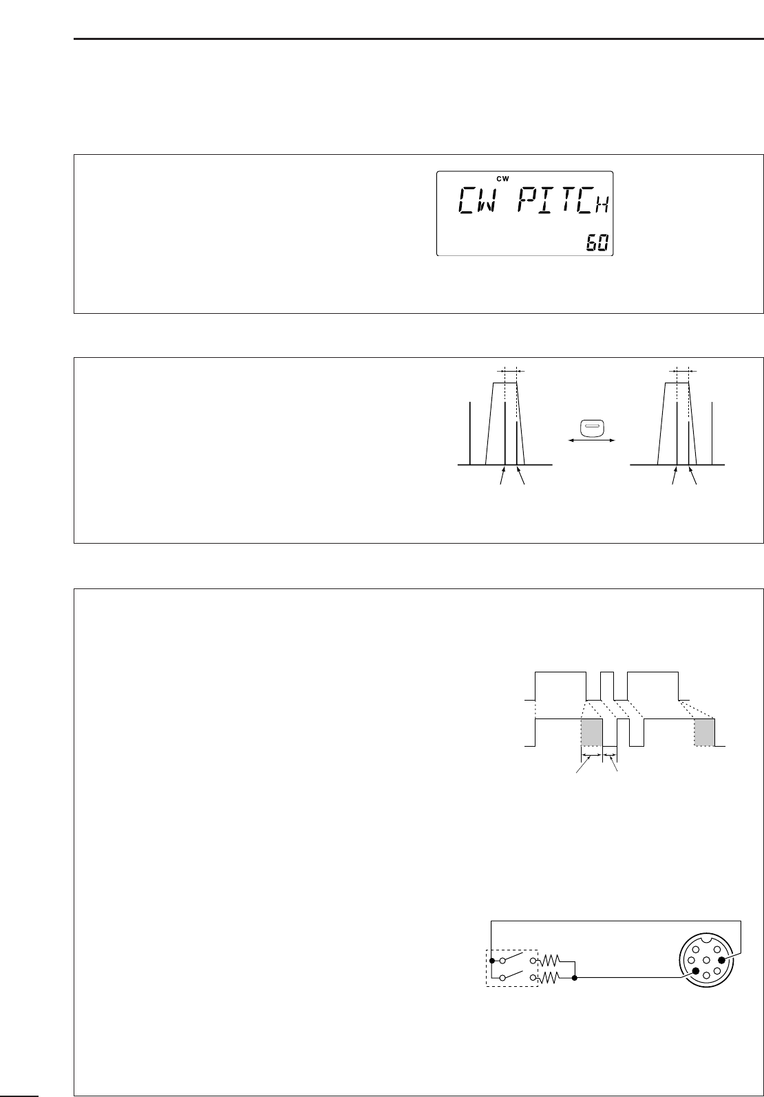
■ Functions for CW............................................. 23
■ Functions for RTTY ......................................... 25
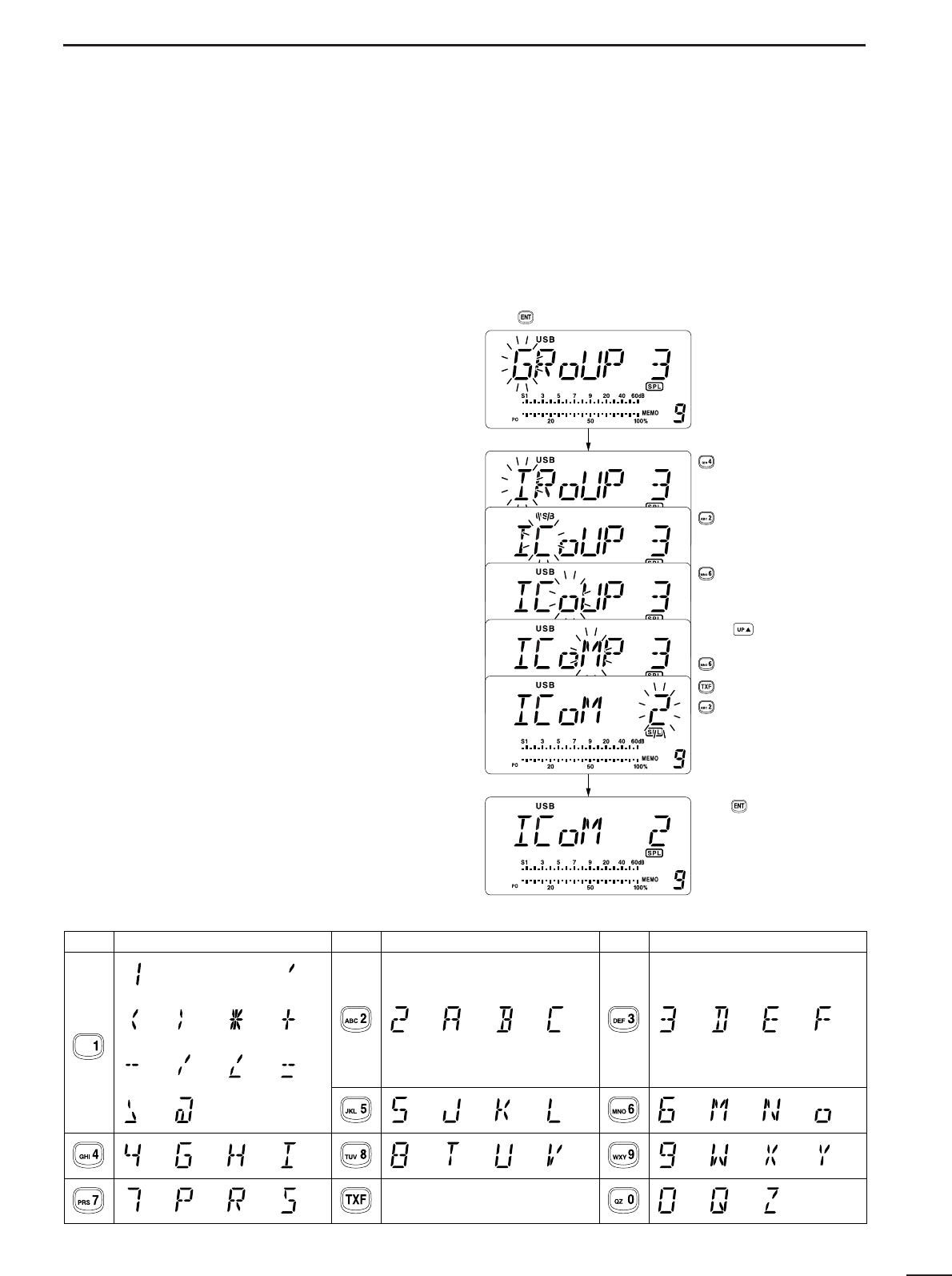
■ Channel comment programming..................... 27
5 SET MODE ................................................... 28–33
■ General............................................................ 28
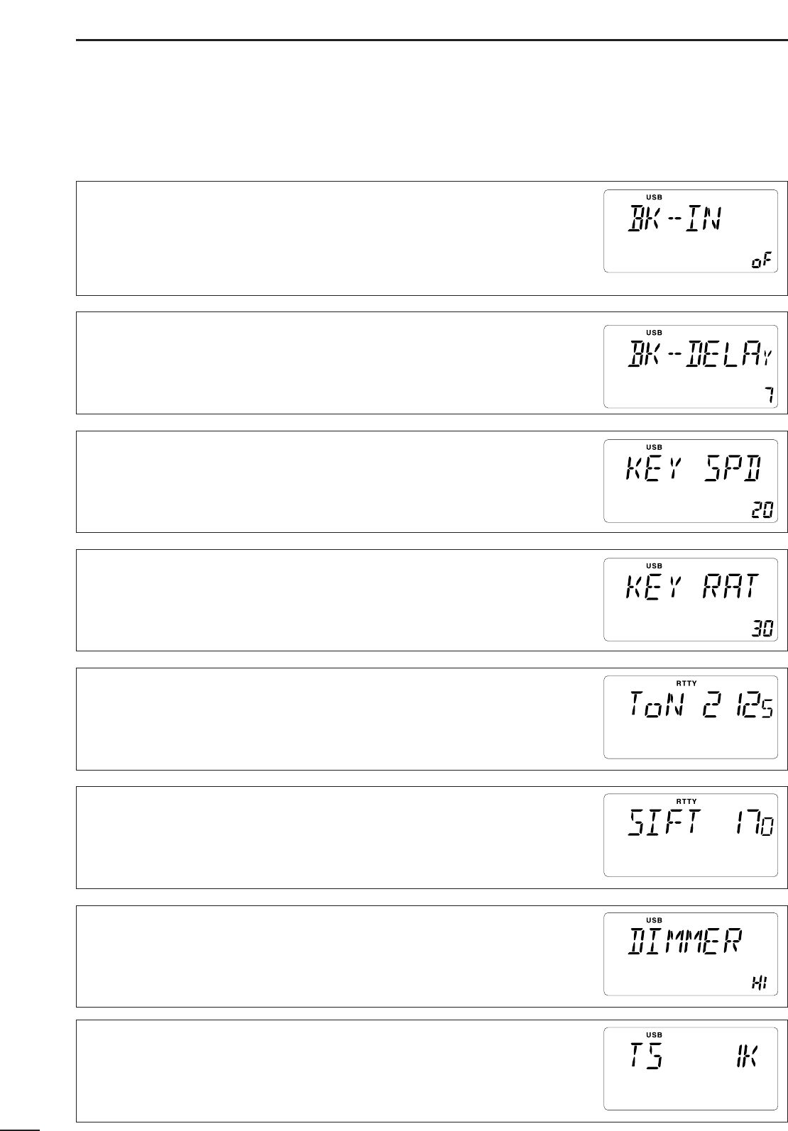
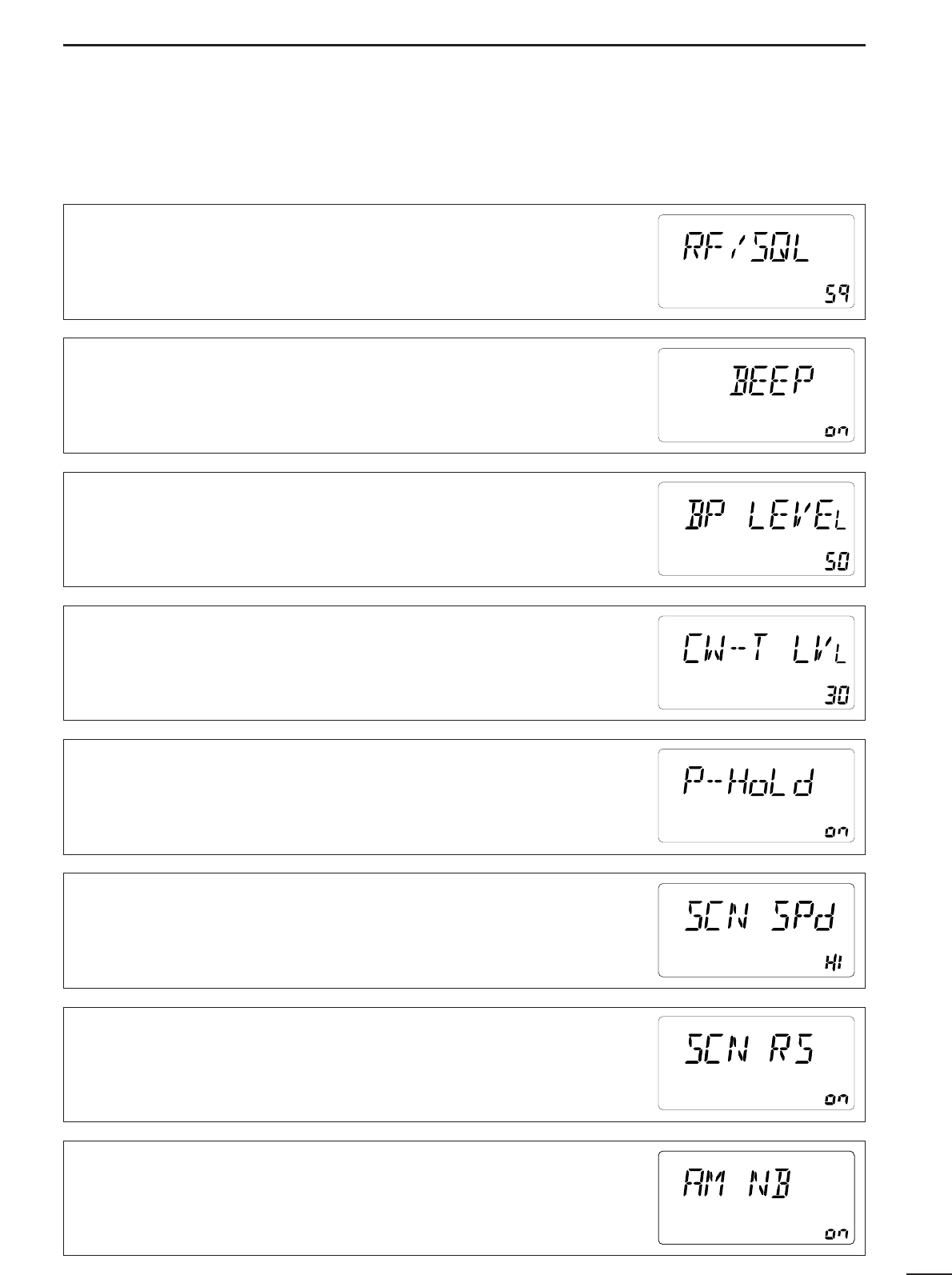
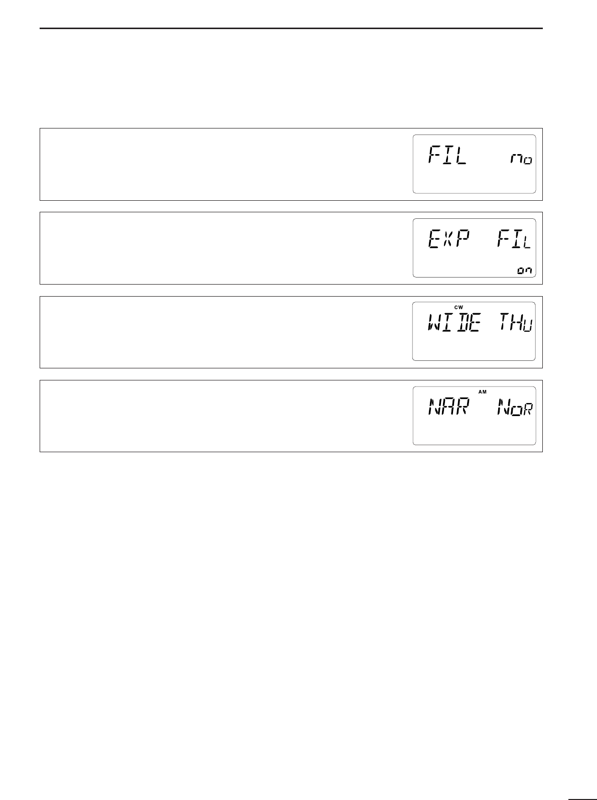
■ Quick set mode items...................................... 29
■ Initial set mode items....................................... 31
6 EXTRA FEATURES...................................... 34–36
■ Instruction........................................................ 34
■ VFO operation................................................. 34
■ 2-Tone alarm operation ................................... 36
7 INSTALLATION AND CONNECTIONS ........ 37–38
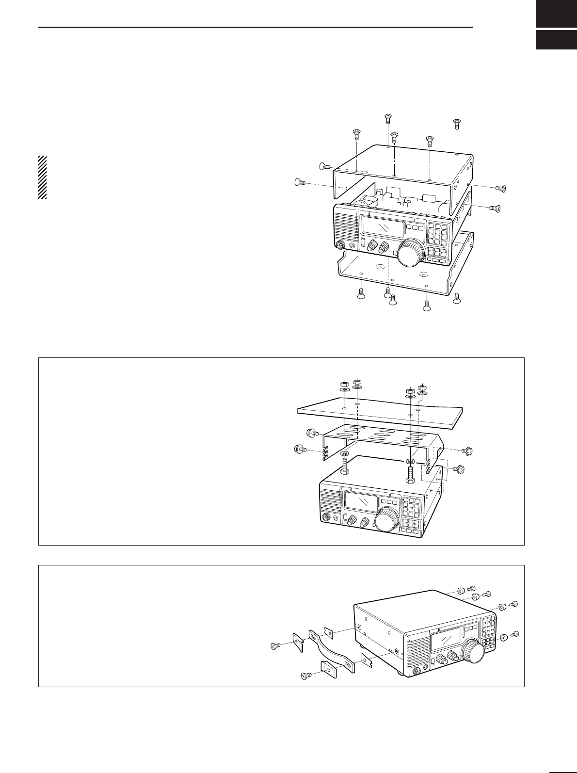
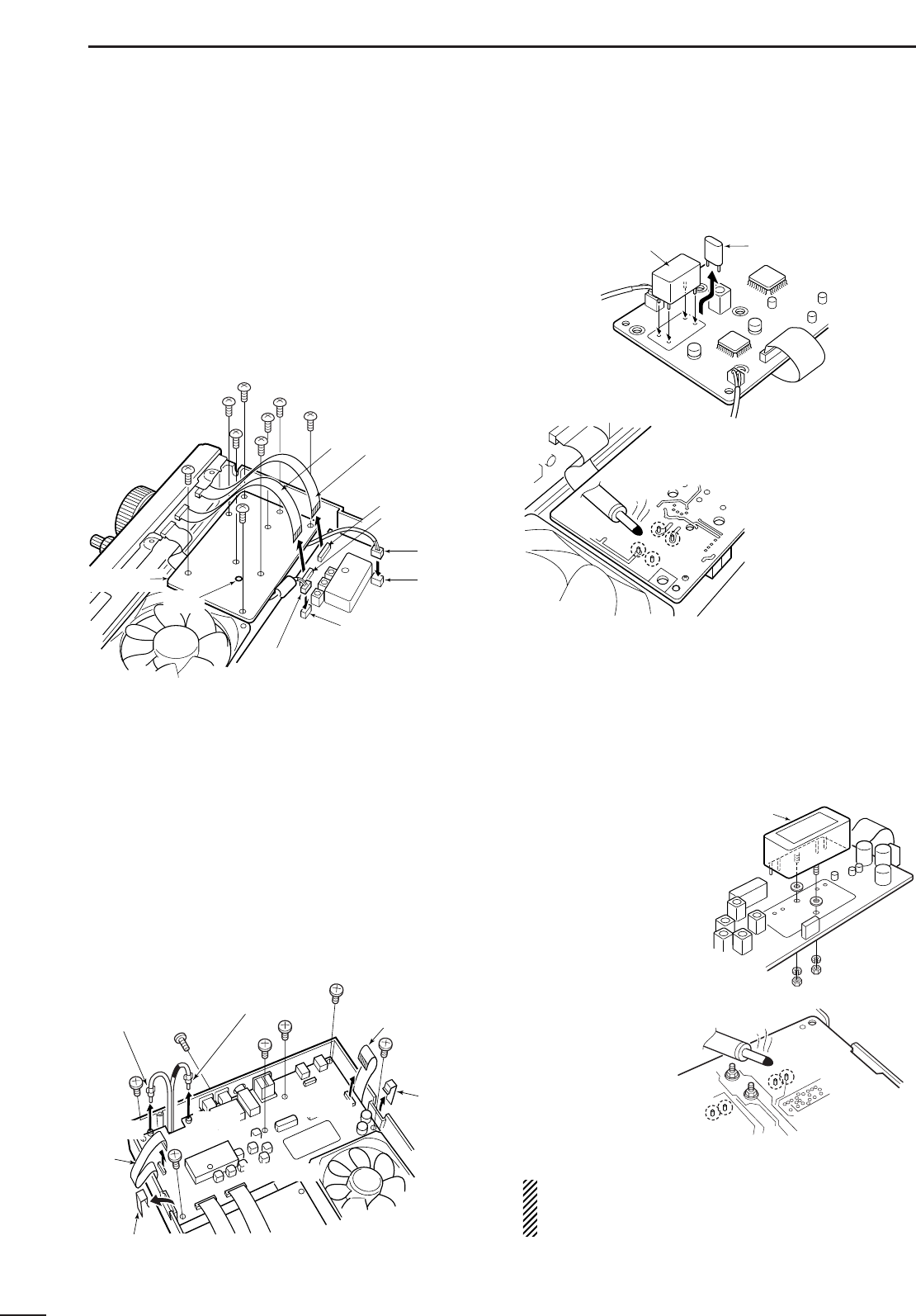
■ Opening the transceiver’s case ...................... 37
■ Optional bracket and carrying handle.............. 37
■ CR-338 HIGH STABILITY CRYSTAL UNIT ......... 38
■ Optional IF filters ............................................ 38
8 MAINTENANCE ........................................... 39–40
■ Troubleshooting .............................................. 39
■ Fuse replacement ........................................... 40
■ Resetting the CPU .......................................... 40
9 REMOTE JACK INFORMATION.................. 41–42
■ CI-V remote control ......................................... 41
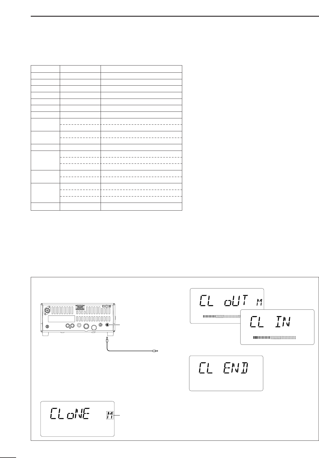
■ Data cloning between transceivers ................. 42
10 SPECIFICATIONS ........................................... 43
12 OPTIONS .................................................. 44–45
SUPPLIED ACCESSORIES
The transceiver comes with the following accessories.
Qty.
q DC power cable.................................................... 1
w Hand microphone (HM-36) .................................. 1
e Fuse (FGB 20 A; for DC cable) ............................ 1
r Fuse (FGB 4 A; internal use) ............................... 1