FOREWORD ........................................................................ i
EXPLICIT DEFINITIONS ..................................................... i
CAUTIONS ........................................................................... i
SUPPLIED ACCESSORIES................................................. ii
TABLE OF CONTENTS ...................................................... iii
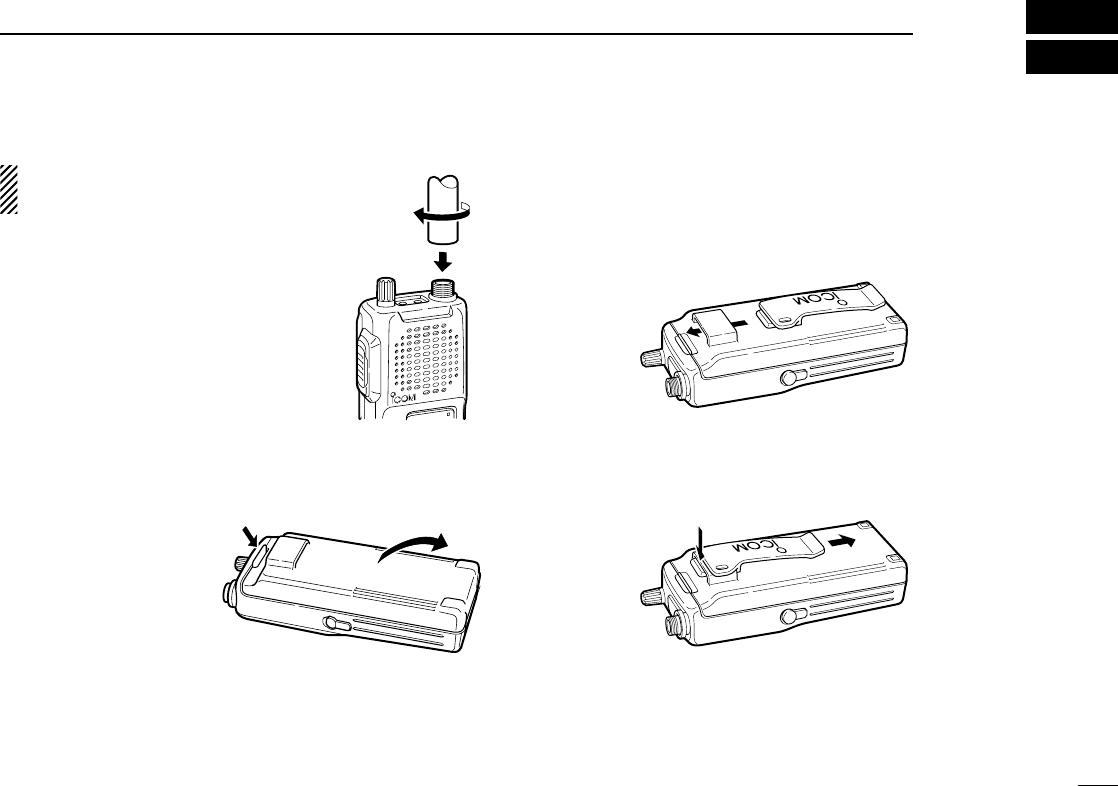
1 ACCESSORY ATTACHMENT ....................................... 1
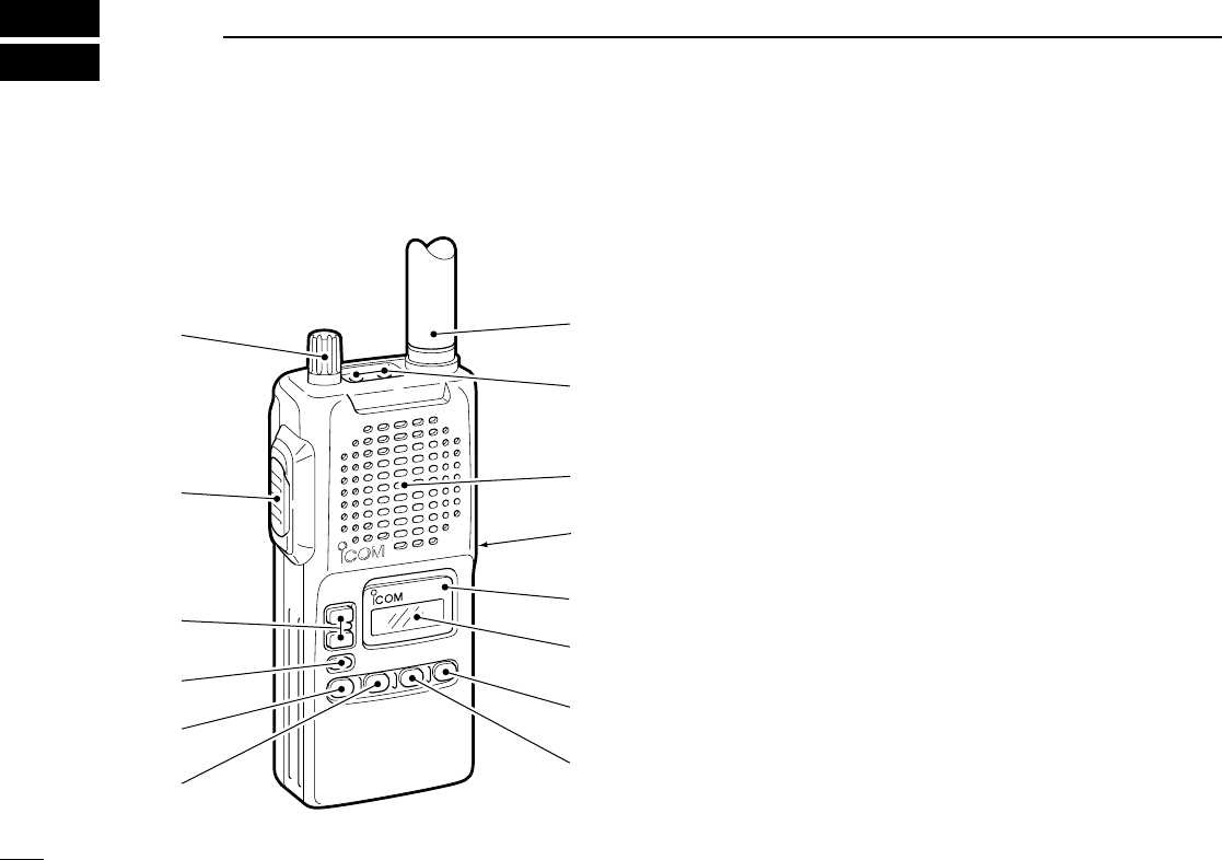
2 PANEL DESCRIPTION ............................................ 2–4
■Panel description ........................................................ 2
■Function display .......................................................... 4
3 BASIC OPERATION ................................................ 5 –7
■Receiving and transmitting ......................................... 5
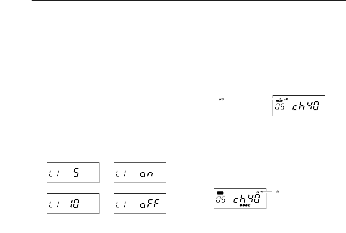
■Display backlighting .................................................... 6
■Lock function .............................................................. 6
■Monitor function .......................................................... 6
■Repeater operation ..................................................... 7
4 SCAN OPERATION ................................................ 8–10
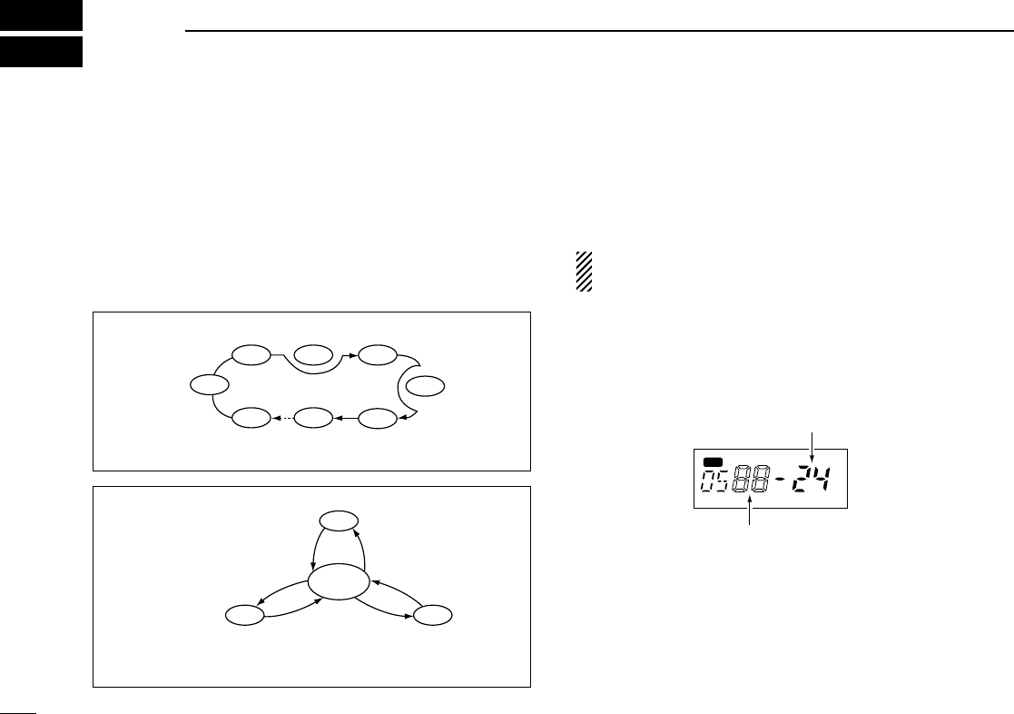
■Scan types .................................................................. 8
■Open scan .................................................................. 8
■Group and priority scans ............................................ 9
■Setting scan tag .......................................................... 9
■Scan resume condition ............................................. 10
5 TONE SQUELCH OPERATION .................................. 11
■Tone squelch operation ............................................ 11
■Pocket beep operation .............................................. 11
6 BATTERY PACKS ................................................ 12– 14
■Charging precautions ............................................... 12
■Battery pack charging ............................................... 12
■About the battery pack .............................................. 14
■Installing batteries in the battery case ...................... 14
7 OTHER FUNCTIONS ........................................... 15–16
■Time-out timer .......................................................... 15
■Power saver .............................................................. 15
■Confirmation beeps .................................................. 15
■Transmit lockout ........................................................ 16
■Optional HM-75A functions ....................................... 16
8 TROUBLESHOOTING ................................................ 17
9 SPECIFICATIONS ....................................................... 18
10 OPTIONS ..................................................................... 19
iii
TABLE OF CONTENTS