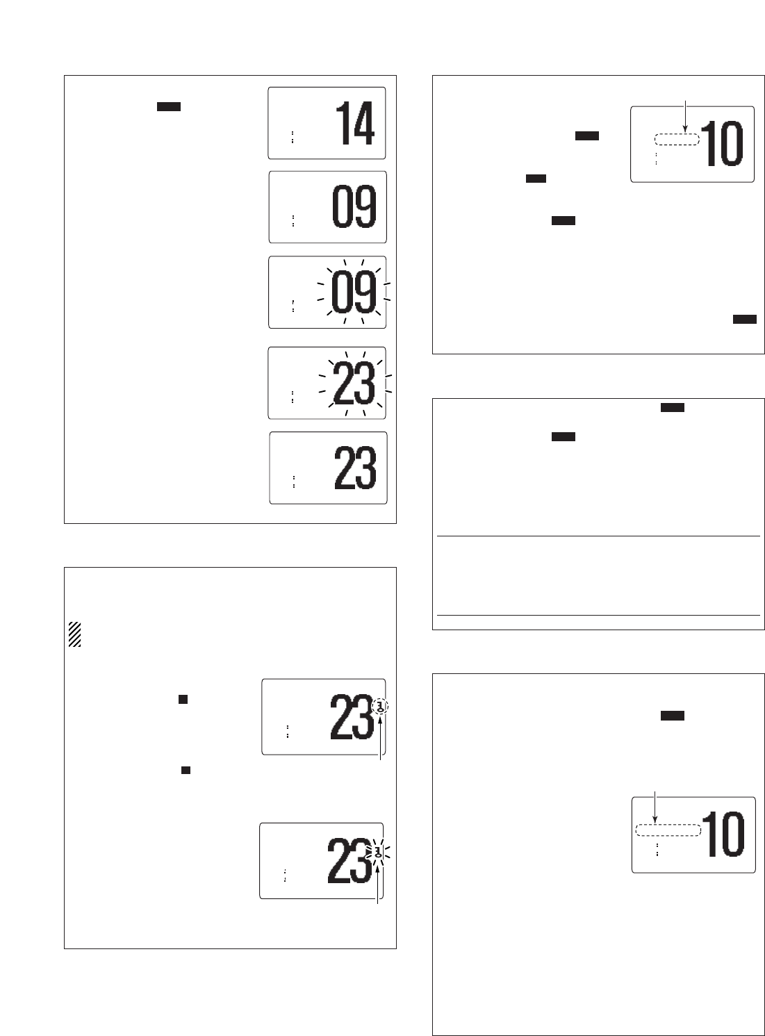
12204
1
Verklein
Vergroot
Pagina terug
1/8
Pagina verder
INSTRUCTIONS
REMOTE-CONTROL MICROPHONE
HM-162B/SW
Thank you for purchasing the HM-162B/SW
REMOTE
-
CONTROL MICROPHONE
. The COMMANDMIC III
TM
is a
remote control microphone for use with the IC-M604
or else.
Please read the connected transceiver’s instruction
manual carefully before installation and operation.
These instructions are just described the remote-
control operations only.
q BUSY/TRANSMIT INDICATOR
BBUUSSYY
” appears when receiving a signal or when the
squelch opens.
TTXX
” appears while transmitting.
w RECEIVER ATTENUATOR INDICATOR
LLOOCC
” appears when the Attenuator function is in use.
e SCRAMBLER INDICATOR
SSCCRRAAMM
” appears when an optional voice scrambler is acti-
vated.
r SCAN INDICATOR
Either “
NNOORRMMAALL SSCCAANN
” or “
PPRRII--SSCCAANN 1166
” scan type
appears while scanning.
DDUUAALL 1166
” appears during dualwatch; “
TTRRII 1166
” ap-
pears during tri-watch.
t SELECTOR STATUS INDICATOR
Indicates the [SELECTOR] active status;
[[VVOOLL]]
” appears when [SELECTOR] as the audio volume.
[[SSQQLL]]
” appears when [SELECTOR] as the noise squelch
controller.
[[CCHH ]]
” appears when [SELECTOR] as the channel selector.
y POSITION INDICATOR
Shows the GPS position data.
•“
????
” may blink every 2 sec. instead of position data when
the GPS position data is invalid. In this case, the last position
data is held for up to 23.5 hours.
•“
????
” may blink every 2 sec. instead of position data 4 hours
after the position data is input manually, up until 23.5 hours
have past.
NNoo PPoossiittiioonn
” appears when no GPS receiver is con-
nected and no position data is input manually.
u TIME ZONE INDICATOR
LLooccaall
” appears when the offset time data in the ‘Set
up’ menu is entered.
NNoo TTiimmee
” appears when no GPS receiver is connected
and no time data is input manually.
i CHANNEL COMMENT INDICATOR
Channel comment appears, if programmed.
o CHANNEL NUMBER READOUT
Indicates the selected operating channel number.
!0 KEY LOCK INDICATOR
Appears while the Key Lock function is in use.
Blinks while the All Key Lock function is in use.
!1 LOW BATTERY INDICATOR
“” blinks when the battery voltage drops to approx. 10 V
DC or below.
!2 CALL CHANNEL INDICATOR
CCAALLLL
” appears when the call channel is selected.
AALLEERRTT
” appears when the Weather Alert function is in
use; blinks when an alert tone is received.
!3 CHANNEL GROUP INDICATOR
Indicates whether an International “
IINNTT
,” U.S.A. “
UUSSAA
,”
Canadian “
CCAANN
” or weather “
WWXX
” channel is selected.
!4 DUPLEX INDICATOR
Appears when a duplex channel is selected.
Duplex channel has a different TX and RX frequency.
!5 TAG CHANNEL INDICATOR
Appears when a tag channel is selected.
!6 POWER INDICATOR
2255WW
” appears when high power is selected.
11WW
” appears when low power is selected.
!7 RX SPEAKER INDICATOR
Appears when an RX speaker function is activated.
BUSYBUSY-25W25W------INTINT------CALLCALL
LOCLOC- -- -- DUPDUP
SCRAMSCRAM--TAGTAG
NORMALNORMAL-SCANSCAN
-3434°34.506N34.506N
123123°23.236W23.236W
LocalLocal----1:101:10- - CALLINGCALLING
RXRX
[VOL]
w
q
e
y
u
r
t
!6!7 !4!5 !3 !2
o
!0
!1
i
Accessories included with the HM-162B/SW: Qty.
q Connection cable (OPC-1540*: 6 m; 20 ft) ....................... 1
w Mounting base .................................................................. 1
e Connector cap .................................................................. 1
r Microphone hanger .......................................................... 1
t Screws (M3 × 16; tapping) ............................................... 5
*: OPC 1540 has external speaker leads as illustrated at right.
(Yellow: Audio, Black: Speaker ground)
These instructions are described when the HM-162 is connected to the IC-M604. Some operations or indications may be dif-
ferent as these instructions depending on the connecting transceiver.
x Function display
z HM-162B/SW supplied accessories
qwe
r
t
Yellow
Black
1
The optional HM-162 remotely controls the transceiver and pro-
vides an optional Intercom function.
q DISTRESS KEY [DISTRESS]
Push for 5 sec. transmit a Distress call.
w TRANSMIT POWER KEY [H/L]
Push to toggle high or low power.
Some Channels are set to low power only.
While pushing this key, other keys perform secondary
functions.
While pushing this key, turn power ON to toggle the All key
Lock function ON or OFF.
•“ ” blinks while the All key Lock function is in use.
Only [PWR] ([CLR]/[MENU]), [DISTRESS] and [PTT] are
functional when the All key Lock function is in use.
e PTT SWITCH [PTT]
Push and hold to transmit; release to receive.
r SELECTOR DIAL [SELECTOR]
Rotate to adjust the audio level
, or select the items in DSC
menu, Set mode settings in set mode, etc.
Rotate to select the noise squelch level or operating chan-
nel after pushing
[VOL/SQL•MONI ].
Rotate to adjust the brightness of the LCD and key back-
light while pushing [H/L].
Checks TAG channels or changes scanning direction dur-
ing scan.
Rotate to adjust the audio level during in hailer mode.
Rotate [SELECTOR] then push [ENT] to adjust the audio
level during in RX Speaker mode.
t ENTER KEY [ENT]
Push to x the selected contents, or select Set mode set-
tings, etc.
Push for 1 sec. to indicate the GPS information of the con-
nected transceiver.
No information appears when GPS receiver is not con-
nected to the transceiver.
y CLEAR•POWER KEY [CLR•PWR]
While HM-162’s power is OFF, push this key and [MENU]
for 1 sec. to turn the power ON.
The connected transceiver power is also turned ON, if it’s
OFF.
While HM-162’s power is ON;
While pushing this key, push [MENU] to turn the HM-
162 power OFF.
The connected transceiver power is also turned OFF de-
pending on the transceiver’s Set mode setting.
Push to clear the selected contents, or select Set mode
settings, etc.
u DSC MENU KEY [MENU]
Toggles the DSC menu ON or OFF when pushed.
While pushing [CLR], push this key to turn the HM-162
power ON and OFF.
i SCAN KEY [SCAN•TAG]
Push to start and stop Normal or Priority scan when TAG
channels are programmed.
Push for 1 sec. to set the displayed channel as a TAG
(scanned) channel.
While pushing [H/L], push for 3 sec. to clear or set all TAG
channels.
o CHANNEL/DUALWATCH/TRI-WATCH KEY
[CH/WX•DW ]
Push to select and toggle the regular channels and
weather channels.
While pushing [H/L], push to select one of three channel
groups in sequence.
U.S.A., International and Canadian channels are available.
Push for 1 sec. to start Dualwatch or Tri-watch.
Push to stop Dualwatch or Tri-watch when either is acti-
vated.
Move the cursor backward while in the channel comment
programming condition.
!0 CHANNEL 16/CALL CHANNEL KEY [16•9]
Push to select Channel 16.
Push for 1 sec. to select call channel.
“CALL” appears when call channel is selected.
Push for 3 sec. to enter call channel programming condi-
tion when call channel is selected.
While pushing [H/L], push to enter the channel comment
programming condition.
While turning power ON, push to enter Set mode.
Advance the cursor while in channel comment program-
ming condition.
!1 VOLUME/SQUELCH•MONITOR/LOCK KEY
[
VOL/SQL• MONI
]
Push to select the volume, channel or squelch setting con-
dition.
After pushing this key, rotate [SELECTOR] to set the
audio level, channel selection or squelch level.
Push for 1 sec. to turn the monitor function ON.
While pushing [H/L], push this to toggle the (microphone)
Key Lock function ON or OFF.
•“ ” appears while (microphone) Key Lock function is in use.
[PWR] ([CLR]/[MENU]), [PTT], [VOL/SQL], [H/L] and [DIS-
TRESS] still function when the (microphone) Key Lock func-
tion is turned ON.
!2 ATTENUATOR/INTERCOM/SCRAMBLER KEY
[LO/DX•IC ]
Push to toggle the Attenuator function ON or OFF.
•“
LLOOCC
” appears when the Attenuator function is turned ON.
Push for 1 sec. to activate the Intercom function.
Calls the transceiver when pushed and held while in In-
tercom mode.
While pushing [H/L], activates an optional Voice scram-
bler function when it’s installed into the transceiver.
•“
SSCCRRAAMM
” appears when the Voice scrambler function is
turned ON.
•Voice scrambler function is available depending on the
transceiver or transceiver’s version.
The optional Voice scrambler function cannot be used on
Channel 16 and 70.
!3 HAILER/RX SPEAKER KEY [HAIL•RX ]
Push to turn the hailer mode ON or OFF.
Push for 1 sec. to turn the RX Speaker mode ON or OFF.
While pushing [H/L], push to turn the automatic foghorn
function ON or OFF.
SCR
é
L
U/I/C
L
é
L
Top keys
Back side
o
i
u
y
!0
!1 !2 !3
w
q
r
t
e
Icom, Icom Inc. and the logo are registered trademarks of Icom Incorporated (Japan) in the United States, the United Kingdom, Germany, France, Spain, Rus-
sia and/or other countries. COMMANDMIC III is a trademark of Icom Incorporated (Japan) in the United states.
c Panel description
2
q Push [PWR] to turn power ON.
w Set the audio and squelch levels.
Push
[VOL/SQL•MONI ] for 1 sec. to activate the moni-
tor function.
Rotate [SELECTOR
VOL
] to adjust the audio output level.
Push
[VOL/SQL•MONI ]
to cancel the monitor function
.
Push
[VOL/SQL•MONI ]
several times, then rotate [SE-
LECTOR
SQL
] to adjust the squelch level.
e While pushing [H/L], push [CH/WX•DW ] to change the
channel group, if desired.
r
Push [CH/WX•DW ] once, then rotate [SELECTOR
CH
]
to select the desired channel.
When receiving a signal, “
BBUUSSYY
” appears and audio is emit-
ted from the speaker.
Further adjustment of the audio level may be necessary.
t Push [LO/DX•IC ] to turn the Attenuator function ON or
OFF, if necessary.
•“
LLOOCC
” appears when the Attenuator function is in use.
y Push [H/L] to select the output power, if necessary.
•“
11WW
” appears when low power is selected.
Choose low power for short range communications, choose
high power for longer distance communications.
Some channels are for low power only.
u Push and hold [PTT] to transmit, then speak into the micro-
phone.
•“
TTXX
” appears.
Channel 70 cannot be used for transmission other than DSC.
Simplex channels, 3, 21, 23, 61, 64, 81, 82 and 83 CAN-
NOT be lawfully used by the general public in U.S.A. wa-
ters.
i Release [PTT] to receive.
IMPORTANT: To maximize the readability of your transmit-
ted signal (voice), pause a few sec. after pushing [PTT],
hold the microphone 2 to 4 inches (5 to 10 cm) from your
mouth and speak at a normal voice level.
SCR
U/I/C
U/I/C
L
L
L
The HM-162 has a selector dial, which works various functions.
Each pushing
[VOL/SQL] changes [SELECTOR]’s action.
Selector status indicator shows “
[[VVOOLL]]
,” “
[[SSQQLL]]
” or
[[CCHH ]]
” when [SELECTOR] functions
as an audio volume,
squelch controller or channel selector, respectively.
Pushing
[CH/WX] changes [SELECTOR]’s action to channel
selector.
• “
[[CCHH ]]
” appears.
Pushing
[ENT] or [CLR] returns [SELECTOR]’s action to the
audio volume when
[[SSQQLL]]
” or “
[[CCHH ]]
” is indicated on the
display
.
Even If [ENT] or [CLR] hasn’t been pushed, [SELECTOR]’s
action returns to the audio volume automatically after 5 sec. of
inactivity.
After these instructions describe [SELECTOR] as follow:
[SELECTOR
VOL
] : Functions as the audio volume.
[SELECTOR
SQL
] : Functions as the squelch controller.
[SELECTOR
CH
] : Functions as the channel selector.
[SELECTOR] : Functions as the any other selector or
controller.
v Selectors action
b Channel selection n Receiving and transmitting
m Monitor function
DD
Channel 16
q Push [16•9] to select Channel 16.
w Push [CH/WX] to return to the
condition before selecting Chan-
nel 16, (or rotate [SELECTOR
CH
] to select an other channel.
DD
Call channel
q Push [16•9] for 1 sec. to select
call channel.
w Push [CH/WX] to return to the
condition before selecting call
channel, (or rotate [SELECTOR
CH
] to select an other channel.
DD
Weather channels
q Push [CH/WX] once or twice to
select the weather channel group.
w Rotate [SELECTOR
CH
] to select
a weather channel.
e Push [CH/WX] once or twice to
return to the condition before se-
lecting the weather channel
group.
DD
U.S.A., International and Canadian channels
q Push [CH/WX•DW ] to select a regular channel.
• Push [CH/WX•DW ] again, if a weather channel appears.
w While pushing [H/L], push [CH/WX•DW ] to select a
channel group.
U.S.A., International and Canadian channels can be selected
in sequence.
e Push [CH/WX•DW ] then rotate [SELECTOR
CH
] to se-
lect a channel.
•“
DDUUPP
” appears for duplex channels.
•“ ” appears when a simplex channel is selected.
BUSY
-25W
25W
---
---
CAN
CAN
---CALL
---CALL
LOCAL--DUP
LOCAL--DUP
SCRAM
SCRAM
--TAG
--TAG
NORMAL-SCAN
NORMAL-SCAN
-34"34.206N
34"34.206N
123"23.236W
123"23.236W
--
--
UTC
UTC
-10:10
10:10
---
---
CCG
CCG
[VOL]
[VOL]
BUSY
-25W
25W
---
---
INT
INT
---CALL
---CALL
LOCAL--
LOCAL--
DUP
DUP
SCRAM
SCRAM
--TAG
--TAG
NORMAL-SCAN
NORMAL-SCAN
-34"34.206N
34"34.206N
123"23.236W
123"23.236W
--
--
UTC
UTC
-10:10
10:10
-TELEPHONE
TELEPHONE
[VOL]
[VOL]
BUSY
-25W
25W
---
---
USA
USA
---CALL
---CALL
LOCAL--DUP
LOCAL--DUP
SCRAM
SCRAM
--
--
TAG
TAG
NORMAL-SCAN
NORMAL-SCAN
-34"34.206N
34"34.206N
123"23.236W
123"23.236W
--
--
UTC
UTC
-10:10
10:10
---
---
CCG
CCG
[VOL]
[VOL]
U.S.A. channels
Canadian channels International channels
U/I/C
U/I/C
U/I/C
U/I/C
BUSY-25W----25W---WXWX---CALL---CALL
LOCAL--DUPLOCAL--DUP
SCRAMSCRAM--TAG--TAG
NORMAL-SCANNORMAL-SCAN
-34"34.206N34"34.206N
123"23.236W123"23.236W
----UTCUTC-10:10162.550MHz10:10162.550MHz
[CH[CH-]
Push
CH/WX
BUSY-25W25W------INTINT---CALL---CALL
LOCAL--DUPLOCAL--DUP
SCRAMSCRAM----TAGTAG
NORMAL-SCANNORMAL-SCAN
-34"34.206N34"34.206N
123"23.236W123"23.236W
----UTCUTC-10:1010:10-CALLINGCALLING
[CH[CH-]
for 1 sec.
916
Push
BUSY-25W25W------INTINT---CALL---CALL
LOCAL--DUPLOCAL--DUP
SCRAMSCRAM----TAGTAG
NORMAL-SCANNORMAL-SCAN
-34"34.206N34"34.206N
123"23.236W123"23.236W
----UTCUTC-10:1010:10- - CALLINGCALLING
[CH[CH-]
916
Push
The monitor function releases the noise squelch mute of the
microphone only. (An independent noise squelch system is
employed.)
Push
[VOL/SQL•MONI ]
for
1 sec. to activate the Monitor
function.
•“
BBUUSSYY
” blinks and audio is emit-
ted.
[VOL/SQL•MONI ] (or [ENT],
[CLR])
cancels the Monitor func-
tion
.
L
L
BUSYBUSY-25W25W------INTINT---CALL---CALL
LOCAL--DUPLOCAL--DUP
SCRAMSCRAM--TAG--TAG
NORMAL-SCANNORMAL-SCAN
-34"34.206N34"34.206N
123"23.236W123"23.236W
----UTCUTC-10:10COMMERCIAL10:10COMMERCIAL
[VOL][VOL]
Blinks
3
Set scan type (Priority or Normal scan) and scan resume timer
in advance, using Set mode.
q While pushing [H/L], push [CH/WX•DW ] several times
to select the desired channel group (USA, INT or CAN).
w Set TAG channels as described at previous item.
e Make sure the squelch is closed to start a scan.
r Push [SCAN•TAG] to start Pri-
ority or Normal scan.
•“
PPRRII--SSCCAANN 1166
”or “
NNOORRMMAALL
SSCCAANN
” appears during Priority
or Normal scan, respectively.
When a signal is detected, scan
pauses until the signal disap-
pears or resumes after pausing
5 sec. according to the Set mode
setting (Channel 16 is still moni-
tored during Priority scan).
Rotate [SELECTOR
CH
] to check the scanning TAG channels,
to change the scanning direction or resume the scan manu-
ally.
•“
1166
blinks at the channel comment indicator and a beep tone
sounds when a signal is received on Channel 16 during Prior-
ity scan.
t To stop the scan, repeat step r.
BUSYBUSY-25W25W------INTINT---CALL---CALL
LOCAL--DUPLOCAL--DUP
SCRAMSCRAM----TAGTAG
NORMALNORMAL-SCANSCAN
-34"34.206N34"34.206N
123"23.236W123"23.236W
----UTCUTC-10:10COMMERCIAL10:10COMMERCIAL
[CH[CH-]
During normal scan
Appears
U/I/C
, Call channel programming ⁄0 Dualwatch/Tri-watch operation
⁄1 Setting TAG channels
⁄2 Starting a scan
. Lock functions
q While pushing [H/L], push
[CH/WX•DW ] several times
to select the desired channel
group (USA, INT, CAN) to be pro-
grammed.
w Push [16•9] for 1 sec. to select call
channel of the selected channel
group.
•“
CCAALLLL
” and call channel number
appear.
e Push [16•9] again for 3 sec. (until
a long beep changes to 2 short
beeps) to enter the call channel
programming condition.
The channel number to be pro-
grammed blinks.
r Rotate [SELECTOR
CH
] to select
the desired channel.
t Push [16•9] to program the dis-
played channel as the call channel.
The channel number stops blinking.
• Push [CH/WX] to cancel.
BUSY
-25W---INT---CALL
LOCAL--DUP
SCRAM--TAG
NORMAL-SCAN
-34"34.206N
123"23.236W
--UTC-10:10- INTL
[CH-]
BUSY
-25W---INT---CALL
LOCAL--DUP
SCRAM--TAG
NORMAL-SCAN
-34"34.206N
123"23.236W
--UTC-10:10- INTL
[CH-]
BUSY
-25W---INT---CALL
LOCAL--DUP
SCRAM--TAG
NORMAL-SCAN
-34"34.206N
123"23.236W
--UTC-10:10-CALLING
[CH-]
BUSY
-25W---INT---CALL
LOCAL--DUP
SCRAM--TAG
NORMAL-SCAN
-34"34.206N
123"23.236W
--UTC-10:10-CALLING
[CH-]
U/I/C
BUSY
-25W---INT---CALL
LOCAL--DUP
SCRAM--TAG
NORMAL-SCAN
-34"34.206N
123"23.236W
--UTC-10:10- VTS
[VOL]
The Lock function electronically locks keys and switches to
prevent accidental changes and function access from the mi-
crophone.
All keys, switches and controllers on the transceiver are
functional.
DD
Activating the Lock function
While pushing [H/L], push
[VOL/SQL•MONI ]
to turn the
Lock function ON or OFF.
•“ ” appears.
Only [PWR] ([CLR]/[MENU]),
[DISTRESS], [PTT], [H/L],
[VOL/SQL•MONI ]
and [SE-
LECTOR] are functional.
DD
Activating the All Key Lock function
While pushing [H/L], turn the
power ON by pushing [PWR] to
turn the All Key Lock function ON
or OFF.
•“ ” blinks.
Only [PWR] ([CLR]/[MENU]),
[DISTRESS] and [PTT] are func-
tional.
é
BUSY-25W25W------INTINT------CALLCALL
LOCAL--LOCAL--DUPDUP
SCRAMSCRAM--TAG--TAG
NORMAL-SCANNORMAL-SCAN
-34"34.206N34"34.206N
123"23.236W123"23.236W
----UTCUTC-10:1010:10- - INTLINTL
[CH-][CH-]
Blinks
L
é
L
BUSY-25W25W------INTINT---CALL---CALL
LOCAL--LOCAL--DUPDUP
SCRAMSCRAM--TAG--TAG
NORMAL-SCANNORMAL-SCAN
-34"34.206N34"34.206N
123"23.236W123"23.236W
----UTCUTC-10:1010:10- - INTLINTL
[CH-][CH-]
Appears
q Select Dualwatch or Tri-watch in
Set mode.
w Rotate [SELECTOR
CH
] after
pushing [CH/WX•DW ] to
select the desired channel.
While pushing [H/L], push
[CH/WX•DW ] several times
to select the channel group
(USA, INT, CAN), if desired.
e Push [CH/WX•DW ] for 1 sec. to start Dualwatch or Tri-
watch.
•“
DDUUAALL 1166
” appears during Dualwatch; “
TTRRII 1166
” appears
during Tri-watch.
•Abeep tone sounds when a signal is received on Channel 16.
•Tri-watch becomes Dualwatch when receiving a signal on the
call channel.
r To cancel Dualwatch or Tri-watch, push [CH/WX•DW ]
again.
U/I/C
U/I/C
U/I/C
U/I/C
BUSYBUSY-25W25W------INTINT---CALL---CALL
LOCAL--DUPLOCAL--DUP
SCRAMSCRAM--TAG--TAG
--------DUALDUAL-1616
-34"34.206N34"34.206N
123"23.236W123"23.236W
----UTCUTC-10:10COMMERCIAL10:10COMMERCIAL
[VOL][VOL]
Appears
q While pushing [H/L], push [CH/WX•DW ] several times
to select the desired channel group (USA, INT or CAN).
w Push [CH/WX•DW ] then rotate [SELECTOR
CH
] to se-
lect the desired channel to be set as a TAG channel.
e Push [SCAN•TAG] for 1 sec. to set the displayed channel
as a TAG channel.
•“
TTAAGG
” appears in the display.
r To cancel the TAG channel setting, repeat step e.
•“
TTAAGG
” disappears.
Clearing (or setting) all tagged channels
While pushing [H/L], push [SCAN•TAG] for 3 sec. (until a long
beep changes to 2 short beeps) to clear all TAG channels in
the channel group.
Repeat above procedure to set all TAG channels.
U/I/C
U/I/C
4
⁄3 Display backlight
The function display and keys can be backlit for better visibility
under low light conditions. The backlighting condition can also
be adjusted independently from the transceiver.
While pushing [H/L], rotate [SE-
LECTOR] to adjust the backlight
level.
•“
BBAACCKKLLIIGGHHTT
” with the back-
light level appears.
The backlight is adjustable in 7
levels and OFF.
BUSY-25W25W------INTINT---CALL---CALL
LOCAL--DUPLOCAL--DUP
SCRAMSCRAM--TAG--TAG
NORMAL-SCANNORMAL-SCAN
BACKLIGHTBACKLIGHT
-7
-<ENT<ENT˘OK> COMMERCIALOK> COMMERCIAL
Appears
⁄4 RX Speaker function
q Push [HAIL• RX ] for 1 sec. to
enter the RX Speaker mode.
•“ ” indicator appears.
The audio output level for the RX
speaker can be adjusted when
entering this mode. Rotate [SE-
LECTOR] then push [ENT].
Or while pushing [HAIL• RX ], rotate [SELECTOR] before
tuning OFF this function (within for 1 sec.).
w To cancel the RX Speaker mode, repeat step q.
•“ ” indicator disappears.
BUSYBUSY-25W25W------INTINT---CALL---CALL
LOCALOCARXRX
--
UPUP
SCRAMSCRAM----TAGTAG
NORMAL-SCANNORMAL-SCAN
RXRX-
15154"34.206N4"34.206N
123"23.236W123"23.236W
-<ENT<ENT˘OK>OK>---- CALLINGCALLING
[CH[CH-]
⁄6 Hailer function
q Push [HAIL• RX ] to enter
the hailer mode.
w Push and hold [PTT] and speak
at a normal voice level.
•“
TTAALLKK
” appears.
•“
WWAAIITT
” appears while the trans-
ceiver side is in use.
•To adjust the hailer level, rotate [SELECTOR].
e After speaking, release [PTT].
r To cancel the hailer mode, repeat step q.
Pushing [16•9] also cancels the hailer function.
While in the hailer mode, the transceiver functions (transmit
and receive) are interrupted. If the transceiver is in transmit
condition, the hailer function is not available.
BUSY-25W---INT---CALLBUSY-25W---INT---CALL
LOCAL--DUPLOCAL--DUP
SCRAM--TAGSCRAM--TAG
NORMAL-SCANNORMAL-SCAN
HAILERHAILER
LISTENLISTEN
1515.236W.236W
_______al--1:10--CALLINGl--1:10--CALLING
⁄7 Automatic foghorn
The automatic foghorn function sounds a horn repeatedly until
the function is turned OFF. Four patterns are available for vary-
ing conditions.
The foghorn outputs from the hailer speaker. To use this func-
tion, the hailer speaker must be connected to the transceiver.
See the transceiver’s instruction manual for connection details.
The audio frequency of the foghorn is selectable in Set
mode.
q While pushing and holding [H/L],
push [HAIL• RX ] to enter auto
foghorn mode.
w Rotate [SELECTOR] to select
the desired foghorn pattern,
push [ENT].
•‘
UUNNDDEERRWWAAYY
,’
SSTTOOPP
,’
SSAAIILL
,’
TTOOWW
are available.
Even if [ENT] hasn’t been pushed, the display automatically
changes to the next step after 5 sec. of inactivity.
e Rotate [SELECTOR] to adjust
the foghorn level, push [ENT].
The foghorn level is adjustable in
30 steps.
Even if [ENT] hasn’t been
pushed, the display automati-
cally changes to the next step
after 5 sec. of inactivity.
[VOL][VOL]
BUSY-BUSY-25W25W------INTINT---CALL---CALL
LOCARXLOCARX
----
UPUP
SCRAMSCRAM----TAGTAG
NORMAL-SCANNORMAL-SCAN
FOGHORNFOGHORN
15154"34.206N4"34.206N
123"23.236W123"23.236W
-<ENT<ENT˘OK>OK>---- CALLINGCALLING
BUSY-BUSY-25W25W------INTINT---CALL---CALL
LOCARXLOCARX
----
UPUP
SCRAMSCRAM----TAGTAG
NORMAL-SCANNORMAL-SCAN
FOGFOG
15154"34.206N4"34.206N
123"23.236W123"23.236W
-UNDERWAYUNDERWAY---- CALLINGCALLING
[VOL][VOL]
The selected foghorn
pattern is displayed.
[VOL][VOL]
BUSY-BUSY-25W25W------INTINT---CALL---CALL
LOCALOCARXRX
--
UPUP
SCRAMSCRAM----TAGTAG
NORMAL-SCANNORMAL-SCAN
˘UNDERWAYUNDERWAY
-STOPSTOP4"34.206N4"34.206N
123"23.236W123"23.236W
-<ENT<ENT˘OK>OK>---- CALLINGCALLING
⁄5 Intercom operation
q Push [LO/DX•IC ] for 1 sec.
to activate the Intercom func-
tion.
w Push and hold [PTT] to talk.
•“
IINNTTEERRCCOOMM TTAALLKK
” appears.
e Release [PTT] to listen.
•“
IINNTTEERRCCOOMM LLIISSTTEENN
” ap-
pears when the transceiver is in
talking mode.
•To adjust the audio outoput level,
push [VOL/SQL] then rotate
[SELECTOR
VOL
].
r Push [LO/DX•IC ] to cancel
the Intercom function.
Pushing [16•9] also cancels the
Intercom function.
For your reference:
In case the Intercom mode is selected with the transceiver while
the microphone power is OFF, the microphone power is auto-
matically turned ON and the Intercom mode is selected.
DD
Intercom beep function
Push and hold [LO/DX•IC ] for more than 1 sec.
Emits the Intercom beep while holding.
SCR
SCR
SCR
BUSY-BUSY-25W---INT-25W---INT---CALL--CALL
LOCAL--DUPLOCAL--DUP
SCRAMSCRAM----TAGTAG
NORMAL-SCANNORMAL-SCAN
INTERCOMINTERCOM
TALKTALK
123"23.236W123"23.236W
--UTC-10:10--UTC-10:10COMMERCIALCOMMERCIAL
BUSY-BUSY-25W---INT-25W---INT---CALL--CALL
LOCAL--DUPLOCAL--DUP
SCRAMSCRAM----TAGTAG
NORMAL-SCANNORMAL-SCAN
INTERCOMINTERCOM
LISTENLISTEN
123"23.236W123"23.236W
--UTC-10:10--UTC-10:10COMMERCIALCOMMERCIAL
AquaQuake helps drain water away from the speaker housing
(water that might otherwise mufe the sound coming from the
speaker). The HM-162 emits a vibrating noise when this func-
tion is being used. This function is availabe depending on the
connected transceiver.
While pushing and holding [PTT], turn power ON to clear
water away from the HM-162.
•Alow beep tone sounds while [PTT] is pushed and held to
drain water, regardless of volume setting.
The HM-162 never accepts a key operation while the
AquaQuake function is activated.
⁄8 AquaQuake water draining function
(Available depending on the transceiver)
5
⁄9 Set mode programming
Set mode is used to change the condition of the transceiver’s
functions and the microphone’s own functions:
Transceiver’s functions—
Scan type, Scan resume timer, Weather alert, Dual/Tri-watch,
Beep tone*
1
, LCD contrast*
1
,Foghorn frequency, Radio Power,
Scrambler Type*
2
and Scrambler code*
2
.
Microphone’s own functions—
Beep tone*
2
, External speaker*
2
and LCD contrast*
2
*
1
For transceiver setting, *
2
For microphone setting,
*
3
Appears only when the optional scramber unit is installed.
In this instructions are for the microphone’s own functions only.
Refer to the transceiver’s instruction for the setting of the other
functions. (Some functions cannot be selected from the HM-
162.)
DD
Entering Set mode
q Turn power OFF.
w While pushing [16•9], turn power ON.
After a beep emission, a Set mode menu appears.
e After the display appears, release [16•9].
r Rotate [SELECTOR] to select the desired item, then push
[ENT].
t Rotate [SELECTOR] to select the desired condition of the
item, then push [ENT].
y Push [CLR] to exit Set mode.
Beep tone
You can select the silent operation by turning beep tones OFF
or you can have conrmation beeps sound at the push of a key
by turning beep tones ON.
LCD contrast
The LCD contrast can be adjustable in 8 levels. 1 is the lowest
contrast, and 8 is the highest contrast.
External speaker
You can select the external speaker ON or OFF. When this set-
ting is set ON, HM-162’ external speaker can be used instead
of internal speaker.
¤1 DSC operation
q Push [MENU] to enter the DSC menu.
w Rotate [SELECTOR] to select the desired item, then push
[ENT].
e Rotate [SELECTOR] to select the setting or condition, then
push [ENT].
Push [CLR] to cancel.
r Push [CLR], or select “
EExxiitt
” in the DSC menu then push
[ENT].
•“
PPoossiittiioonn IInnppuutt
” item appears when the suitable GPS
receiver is not connected.
•“
IInnddiivviidduuaall AACCKK
” item appears after an individual call
is received.
•“
PPoossiittiioonn RReeppllyy
” item appears after a position request
call is received.
•“
PPOOSS RReeppoorrtt RReeppllyy
” item appears after a position report
call is received.
•“
PPoolllliinngg RReeppllyy
” item appears after a polling request call
is received.
--DSC Menu--
Select Item
˘Position Input
Individual Call
Individual ACK
Group Call
All Ships Call
˘Position-Request-----
˘Position-Reply---
˘Position-Report---
˘POS-Report-Reply---
˘Polling-Request--
˘Polling-Reply---
˘Received-Calls
˘Distress-Setting
˘Set-up
˘Exit
¤0 Channel comments
Memory channels can be labelled with a unique alphanumeric
ID of up to 10 characters.
Capital letters, small letters, 0 to 9, some symbols (– . /) and
space can be used.
q Rotate [SELECTOR] after pushing [VOL/SQL] to select a
channel to edit the channel comment.
• While pushing [H/L], push [CH/WX•DW ] several times
to select the channel group (USA, INT, CAN), if desired.
w While pushing [H/L], push [16•9].
•Acursor and the rst character start blinking alternately.
e Select the desired character by rotating [SELECTOR].
• Push [CH/WX•DW ] or [16•9] to move the cursor forward
or backward, respectively.
r Repeat step e to input all characters.
t Push [ENT] to input and set the comment.
Push [CLR] to cancel.
The cursor and the character stop blinking.
y Repeat steps q to t to program other channel comments,
if desired.
U/I/C
U/I/C
¤2 Position and time programming
PPoossiittiioonn IInnppuutt
” item in the DSC menu appears when
a
suitable GPS receiver is not connected.
Manually programmed
position data will be held for 23.5 hours only.
q Select and enter “
PPoossiittiioonn IInnppuutt
” in the DSC menu.
w The position information appears. Rotate [SELECTOR] to
set your position (latitude and longitude) data, then push
[ENT].
• Push [16•9] or [CH/WX] to move the cursor forward or back-
ward, respectively.
• Push [CLR] for 1 sec. to clear the latitude/
longitude
data.
• Push [CLR] to cancel and return to the DSC menu.
e The time information appears. Rotate [SELECTOR] to set
the current UTC time, then push [ENT].
• Push [16•9] or [CH/WX] to move the cursor forward or back-
ward, respectively.
• Push [CLR] for 1 sec. to clear the UTC time data.
• Push [CLR] to cancel and return to the DSC menu.
r Push [CLR] or select “
EExxiitt
” in the DSC menu then push
[ENT].
• Returns to the normal operation mode.
6
¤3 Distress call
The distress call is repeated every 3.5–4.5 min., until re-
ceiving an ‘acknowledgement.’
• Push [CLR] to cancel the ‘Call repeat’ mode.
• “
????
” may blink instead of position and time indications
when the GPS data is invalid, or has not been manually
updated after 4 hours.
DD
Simple call
q Conrm no distress call is being received.
w While pulling down the distress key cover on the back
side, push [DISTRESS] for 5 sec. to transmit the distress
call.
When no GPS is connected, input your position and UTC
time, if possible.
While pushing [DISTRESS], the key backlighting blinks.
e After transmitting the distress call, the transceiver waits for
an acknowledgment call on Channel 70.
Transmitting after 2 sec., the display changes to Channel 16
automatically.
After receiving the acknowledgment, reply using the micro-
phone.
DD
Regular call
The nature of the distress call should be included in the dis-
tress call.
q Select and enter “
DDiissttrreessss SSeettttiinngg
” in the DSC
menu.
w Select and enter the nature of the distress.
•‘Undesignated,’ Explosion,’ Flooding,’ Collision,’
Grounding,’ Capsizing,’ ‘Sinking,’ Adrift (Disable adrift),’
Abandoning (Abandoning ship),’ Piracy (Piracy attack)’ and
MOB (Man overboard)’ are available.
• The selected nature of the distress is stored for 10 minutes.
r Push [DISTRESS] for 5 sec. to transmit the distress call.
While pushing [DISTRESS], the key backlighting blinks.
t After transmitting the distress call, the transceiver waits for
an acknowledgment call on Channel 70.
Transmitting after 2 sec., the display changes to Channel 16
automatically.
After receiving the acknowledgment, reply using the micro-
phone.
e Set your position data and current UTC time. (See ‘¤2 Po-
sition and time programming’ for details.)
When a suitable GPS receiver is connected to the transceiver,
this step is skipped.
Transmitting DSC calls (continued)
DD
Transmitting an individual acknowledgement
IInnddiivviidduuaall AACCKK
” item appears after an individual call is
received.
q Select and enter “
IInnddiivviidduuaall AACCKK
” in the DSC menu.
w Select and enter the desired individual address or ID code.
e Select and enter an acknowledgement “
AAbbllee ttoo CCoomm--
ppllyy
” or “
UUnnaabbllee ttoo CCoommppllyy
.”
r Push [ENT] to transmit the acknowledgement call.
DD
Transmitting a group call
q Select and enter “
GGrroouupp CCaallll
” in the DSC menu.
w Select and enter the desired group address.
e Select and enter a desired intership channel.
r Push [ENT] to transmit the group call.
t Push [CLR] to exit and the transceiver selects the intership
channel specied in step e automatically.
Even if [CLR] hasn’t been pushed, the transceiver selects the
specied intership channel in step e automatically after 2 sec.
of inactivity.
DD
Transmitting an all ships call
q Select and enter “
AAllll SShhiippss CCaallll
” in the DSC menu.
w Select and enter the desired category.
The selectable category may differ according to the connected
transceiver setting.
e Push [ENT] to transmit the all ships call.
r Push [CLR] to exit and the transceiver selects Channel 16
automatically.
Even if [CLR] hasn’t been pushed, the transceiver automati-
cally selects Channel 16 after 2 sec. of inactivity.
DD
Transmitting a position request call
q Select and enter “
PPoossiittiioonn RReeqquueesstt
” in the DSC
menu.
w Select and enter the desired individual address.
e Push [ENT] to transmit the position request call.
r Push [CLR] to return to the previous indication before en-
tering the DSC menu.
Even if [CLR] hasn’t been pushed, the display automatically
returns to the previous indication after 2 sec. of inactivity.
DD
Transmitting a position request reply call
PPoossiittiioonn RReeppllyy
” item appears after a position request
call is received.
q Select and enter “
PPoossiittiioonn RReeppllyy
” in the DSC menu.
w Select and enter the desired individual address.
r Push [ENT] to transmit the position request reply call.
•Your position data is transmitted.
DD
Transmitting a position report call
q Select and enter “
PPoossiittiioonn RReeppoorrtt
” in the DSC
menu.
w Select and enter the desired individual address.
r Push [ENT] to transmit the position report call.
t Push [CLR] to return to the previous indication before en-
tering the DSC menu.
Even if [CLR] hasn’t been pushed, the display automatically
returns to the previous indication after 2 sec. of inactivity.
e Set your position data and current UTC time. (See ‘¤2 Po-
sition and time programming’ for details.)
When a suitable GPS receiver is connected to the transceiver,
this step is skipped.
e Set your position data and current UTC time. (See ‘¤2 Po-
sition and time programming’ for details.)
When a suitable GPS receiver is connected to the transceiver,
this step is skipped.
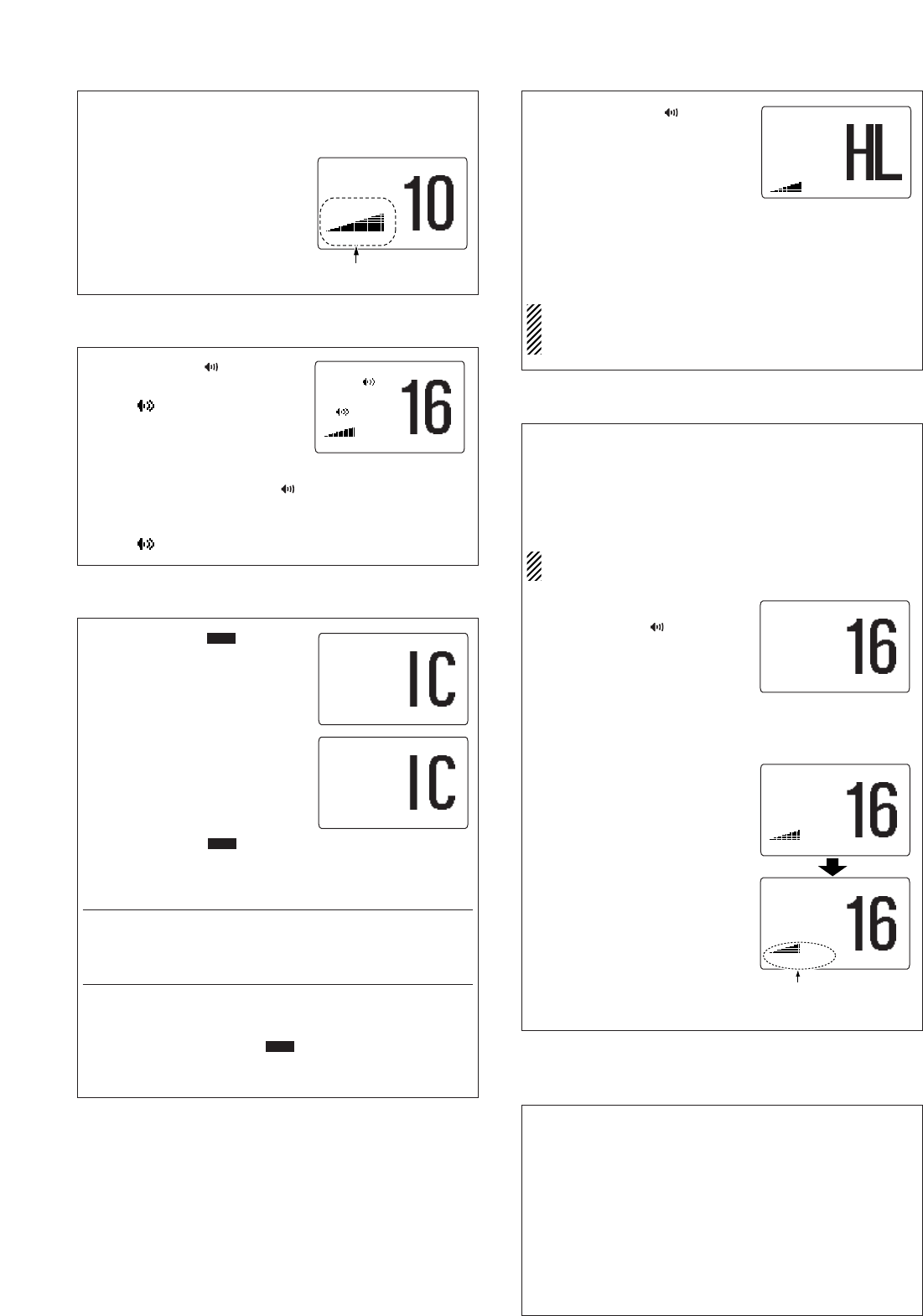
¤4 Transmitting DSC calls
To ensure correct operation of the DSC function, please
make sure you set the squelch correctly.
DD
Transmitting an individual call
q Select and enter “
IInnddiivviidduuaall CCaallll
” in the DSC
menu.
w Select and enter the desired individual address.
e Select and enter a desired intership channel.
r Push [ENT] to transmit the individual call.
t Standby on Channel 70 until an acknowledgement is re-
ceived.
y When the acknowledgement is received, and if it is ‘Able to
comply,’ the display changes to the specified channel (in
step e) is selected with beeps automatically.
Or it is ‘Unable to comply,’ the display returns to the operated
channel (before enter the DSC menu) with beeps.
u Push [CLR] to stop the beep, then push and hold [PTT] to
communicate your message to the responding ship.
7
1-1-32 Kamiminami, Hirano-ku, Osaka 547-0003, Japan
A-6496X-1EX-w
Printed in China
© 2006 Icom Inc.
Transmitting DSC calls (continued)
DD
Transmitting a position report reply call
PPOOSS RReeppoorrtt RReeppllyy
” item appears after a position report
call is received.
q Select and enter “
PPOOSS RReeppoorrtt RReeppllyy
” in the DSC
menu.
w Select and enter the desired individual address.
e Push [ENT] to transmit the position report reply call.
DD
Transmitting a polling request call
q Select and enter “
PPoolllliinngg RReeqquueesstt
” in the DSC
menu.
w Select and enter the desired individual address.
e Push [ENT] to transmit the polling request call.
r Push [CLR] to return to the previous indication before en-
tering the DSC menu.
Even if [CLR] hasn’t been pushed, the display automatically
returns to the previous indication after 2 sec. of inactivity.
DD
Transmitting a polling request reply call
PPoolllliinngg RReeppllyy
” item appears after a polling request call
is received.
q Select and enter “
PPoolllliinngg RReeppllyy
” in the DSC menu.
w Select and enter the desired individual address.
e Push [ENT] to transmit the polling request call.
DSC Set mode (continued)
After entering an 8-digit ID code, push [ENT] or [16•9] to enter
the ID name.
• 1st digit ‘0’ is xed for a group ID.
e After inputting, push [ENT] to program.
r Push [CLR] or select “Exit” in the set up menu then push
[ENT].
• Returns to the DSC menu.
• Repeat again to return to the normal operation condition.
DD
Deleting Individual ID/Group ID
q S
elect and enter “
DDEELL::IINNDDVV IIDD
” or “
DDEELL::GGrroouupp IIDD
in the set up menu.
w Select the desired ID name for deleting.
e Push [ENT] to delete the address ID and return to the set
up menu.
r Push [CLR], or select “
EExxiitt
” in the set up menu then push
[ENT].
• Returns to the DSC menu.
• Repeat again to return to the normal operation condition.
DD
Offset time
q S
elect and enter “
OOffffsseett TTiimmee
” in the set up menu.
w Rotate [SELECTOR] to set the offset time from the UTC
(Universal Time Coordinated) time.
Push [16•9] or [CH/WX] to move the cursor forward or
backward, respectively.
• Push [CLR] to cancel and return to the set up menu.
e Push [ENT] to program and return to the set up menu.
DD
MMSI code check
The 9-digit MMSI (DSC self ID) code can be checked.
q S
elect and enter “
MMMMSSII CChheecckk
” in the set up menu.
w Check the 9-digit MMSI (DSC self ID) code.
e Push [CLR], or select “
EExxiitt
” in the set up menu then push
[ENT].
• Returns to the DSC menu.
• Repeat again to return to the normal operation condition.
DD
Automatic acknowledgement
q S
elect and enter “
AAuuttoo AACCKK
” in the set up menu.
w T
urn the
automatic acknowledgement function ON or OFF
.
e Push [ENT] to set the condition.
• Push [CLR] to cancel and return to the set up menu.
DD
NMEA Output
When receiving position acknowledgment, the transceiver out-
puts it to the external equipment via the NMEA connector.
q S
elect and enter “
NNMMEEAA OOuuttppuutt
” in the set up menu.
w Select the NMEA Output function.
e Push [ENT] to set the condition.
• Push [CLR] to cancel and return to the set up menu.
• List Station: Outputs the position data from the specified
vessels listed on the DSC individual ID screen.
All Station : Outputs the position data from all vessels.
OFF : Does not output any position data to external
equipment.
¤5 Received messages
The transceiver automatically stores up to 20 distress mes-
sages and 20 other messages. The messages can be used as
an assistance to the logbook.
q Select and enter “
RReecceeiivveedd CCaallllss
” in the DSC menu.
w Select and enter “
DDiissttrreessss
” or “
OOtthheerr
.”
e Select and enter the desired message.
Messages which are blinking have not been read.
r Rotate [SELECTOR] to scroll in the message.
t Push [CLR] to exit or push [CLR] for 1 sec. to delete the
displayed message and return to the DSC menu.
¤6 DSC Set mode
q Select and enter “
SSeett uupp
” in the DSC menu.
w Se
lect and enter the desired item.
e Select and enter the desired setting or condition.
Push [CLR] to cancel before pushing [ENT].
r Push [CLR], or select “
EExxiitt
” in the set up menu then push
[ENT].
• Returns to the DSC menu.
• Repeat again to return to the normal operation condition.
DD
Programming Individual ID/Group ID
q S
elect and enter “
AAdddd::IINNDDVV IIDD
” or “
AAdddd::GGrroouupp IIDD
in the set up menu.
w Rotate [SELECTOR]
to s
et the individual ID and ID name
(or group ID and ID name).
• Push [16•9] or [CH/WX] to move the cursor forward or back-
ward, respectively.
• Push [CLR] to cancel and return to the set up menu.
• “
FFuullll IIDD
” appears when all of the DSC address IDs are al-
ready set.
[For individual ID]
After inputting the 9-digit MMSI number, push [ENT] or [16•9]
to enter the ID name.
• 1st digit must not be ‘0’ for a individual ID.
[For Group ID]
The group ID is a unique number that you create for your
group. The ID name is an associated text name for that group.
CLEAN THE HM-162B/SW THOROUGHLY WITH FRESH
WATER after exposure to water including salt water, oth-
erwise, the keys and switch may become inoperable due to
salt crystallization.
1

Hulp nodig? Stel uw vraag in het forum

Spelregels

Misbruik melden

Gebruikershandleiding.com neemt misbruik van zijn services uitermate serieus. U kunt hieronder aangeven waarom deze vraag ongepast is. Wij controleren de vraag en zonodig wordt deze verwijderd.

Product:

Bijvoorbeeld antisemitische inhoud, racistische inhoud, of materiaal dat gewelddadige fysieke handelingen tot gevolg kan hebben.

Bijvoorbeeld een creditcardnummer, een persoonlijk identificatienummer, of een geheim adres. E-mailadressen en volledige namen worden niet als privégegevens beschouwd.

Spelregels forum

Om tot zinvolle vragen te komen hanteren wij de volgende spelregels:

Belangrijk! Als er een antwoord wordt gegeven op uw vraag, dan is het voor de gever van het antwoord nuttig om te weten als u er wel (of niet) mee geholpen bent! Wij vragen u dus ook te reageren op een antwoord.

Belangrijk! Antwoorden worden ook per e-mail naar abonnees gestuurd. Laat uw emailadres achter op deze site, zodat u op de hoogte blijft. U krijgt dan ook andere vragen en antwoorden te zien.

Abonneren

Abonneer u voor het ontvangen van emails voor uw Icom HM-162B SW bij:


U ontvangt een email met instructies om u voor één of beide opties in te schrijven.


Ontvang uw handleiding per email

Vul uw emailadres in en ontvang de handleiding van Icom HM-162B SW in de taal/talen: Engels als bijlage per email.

De handleiding is 0,17 mb groot.


U ontvangt de handleiding per email binnen enkele minuten. Als u geen email heeft ontvangen, dan heeft u waarschijnlijk een verkeerd emailadres ingevuld of is uw mailbox te vol. Daarnaast kan het zijn dat uw internetprovider een maximum heeft aan de grootte per email. Omdat hier een handleiding wordt meegestuurd, kan het voorkomen dat de email groter is dan toegestaan bij uw provider.

Stel vragen via chat aan uw handleiding

Stel uw vraag over deze PDF

Uw handleiding is per email verstuurd. Controleer uw email

Als u niet binnen een kwartier uw email met handleiding ontvangen heeft, kan het zijn dat u een verkeerd emailadres heeft ingevuld of dat uw emailprovider een maximum grootte per email heeft ingesteld die kleiner is dan de grootte van de handleiding.

Er is een email naar u verstuurd om uw inschrijving definitief te maken.

Controleer uw email en volg de aanwijzingen op om uw inschrijving definitief te maken

U heeft geen emailadres opgegeven

Als u de handleiding per email wilt ontvangen, vul dan een geldig emailadres in.

Uw vraag is op deze pagina toegevoegd

Wilt u een email ontvangen bij een antwoord en/of nieuwe vragen? Vul dan hier uw emailadres in.


Info