Use the heating/ventilation system to defrost or defog the windshield:
A Type
B Type
A Type
B Type
1
FEATURES OF YOUR HYUNDAI
102
AUTOMATIC HEATING AND COOLING CONTROL SYSTEM
B970A01Y-AAT
(If installed)
Your Hyundai is equipped with an automatic
heating and cooling control system controlled
by simply setting the desired temperature.
TYPE A (Without A.Q.S: Air Quality System)
B970B01JM
B970B02JM
B970B01JM-GAT
Heating and Cooling Controls
1.Temperature Control Switch
2.Air Flow Control Switch
3.Display Window
4.Defroster Switch
5.Blower Fan Control Switch
6.AUTO (Automatic Control)Switch
7.OFF Switch
8.Air Conditioning Switch
9.Air lntake Control Switch
10. Air Quality System Switch
(If installed)
TYPE B (With A.Q.S: Air Quality System)
1
FEATURES OF YOUR HYUNDAI
103103
103103103
Photo sensor
HJM2086
NOTE:
oIf the battery has been discharged or
disconnected, the temperature mode will
reset to Centigrade degrees.
This is a normal condition and you can
change the temperature mode from Cen-
tigrade to Farenheit as follows;
Press the "TEMP" down button and
"AUTO" button simultaneously for 3
secs. The display shows that the unit of
temperature is adjusted to Centigrade or
Fahrenheit.
(°C
→→
→→
→°F or °F
→→
→→
→°C)
oNever place anything covering the sen-
sor which is located on the instrument
panel to ensure better control of the
heating and cooling system.
B970C01JM-AAT
Automatic Operation
The FATC (Full Automatic Temperature Con-
trol) system automatically controls heating and
cooling by doing as follows:
1.Push the "AUTO" button. The indicator light
will illuminate confirming that the Face, Floor
and/or Bi-Level modes as well as the blower
speed and air conditioner will be controlled
automatically.
2.Push the "TEMP" button to set the desired
temperature.
The temperature will increase to the maxi-
mum 90°F(32°C) by pushing the " " button.
Each push of the button will cause the tem-
perature to increase by 1°F(0.5°C).
The temperature will decrease to the mini-
mum 62°F(17°C) by pushing the " " button.
Each push of the button will cause the tem-
perature to decrease by 1°F(0.5°C).
HJM2124
HJM2126
1
FEATURES OF YOUR HYUNDAI
104
B980B01Y-AAT
Fan Speed Control Switch
The fan speed can be set to the desired speed
by pressing the appropriate fan speed control
button. The higher the fan speed is, the more air
is delivered. Pressing the "OFF" button turns off
the fan.
HJM2123
B980A01Y-AAT
MANUAL OPERATION
The heating and cooling system can be con-
trolled manually as well by pushing buttons
other than the "AUTO" button. In this state, the
system sequentially works according to the
order of buttons selected.
The function of the buttons which are not se-
lected will be controlled automatically.
Press the "AUTO" button in order to convert to
automatic control of the system.
B670C03Y-AAT
Air Intake Control Switch
(Without A.Q.S)
This is used to select fresh outside air or
recirculation inside air.
To change the air intake control mode, (Fresh
mode, Recirculation mode) push the control
button.
FRESH MODE ( ) : The indicator light on the
button goes on when the air intake control is
fresh mode.
RECIRCULATION MODE ( ) : The indicator
light on the button is illuminated when the air
intake control is recirculation mode.
B670C01JM
1
FEATURES OF YOUR HYUNDAI
105105
105105105
B980C02JM-GAT
Air Intake Control Switch
(With A.Q.S) (If installed)
This is used to select fresh outside air or
recirculate inside air automatically.
:OFF
:ON
Fresh Mode :
Air enters the vehicle from the outside and is
heated or cooled according to the function
selected.
Recirculation Mode :
Air from within the passenger compartment will
be drawn through the heating system and heated
or cooled according to the function selected.
Exhaust Gas Cutoff Mode :
Air enters the vehicle from the outside.
But if exhaust gas enters the vehicle from the
outside, the exhaust gas cutoff mode ( )
is automatically converted to the ( ) mode,
to prevent exhaust gas from entering the ve-
hicle.
NOTE:
It should be noted that prolonged opera-
tion of the heating system in recirculation
mode ( ) will give rise to misting of the
windshield and side windows and the air
within the passenger compartment will
become stale. In addition, prolonged use of
the air conditioning with the recirculation
mode ( ) selected may result in the air
within the passenger compartment becom-
ing excessively dry.
B980C01JM
With the "Fresh" mode selected, air enters the
vehicle from the outside and is heated or cooled
according to the function selected.
With the "Recirculation" mode selected, and air
from within the passenger compartment will be
drawn through the heating system and heated
or cooled according to the function selected.
NOTE:
It should be noted that prolonged opera-
tion of the heating system in "recirculation"
mode will give rise to fogging of the wind-
shield and side windows and the air within
the passenger compartment will become
stale. In addition, prolonged use of the air
conditioning with the "Recirculation" mode
selected may result in the air within the
passenger compartment becoming exces-
sively dry.
1
FEATURES OF YOUR HYUNDAI
106
B980D01Y-AAT
Heating and Cooling System Off
Press the "OFF" button to stop the operation of
the heating and cooling system.
!
CAUTION:
If the windows fog up with the Recircula-
tion or A.Q.S mode selected, set the air
intake control to the Fresh air position or
A.Q.S control to "OFF".
HJM2111
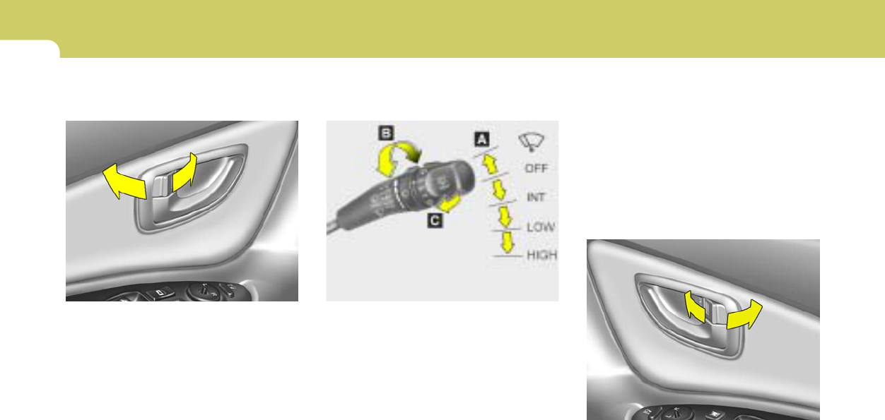
B980E01E-GAT
Air Flow Control
HJM2128
This is used to direct the flow of air. Air can be
directed to the floor, dashboard outlets, or
windshield. Four symbols are used to represent
Face, Bi-Level, Floor and Floor-Defrost air
position.
Face-Level
When selecting the "Face" mode, the indicator
light will come on, causing air to be discharged
through the face level vents.
1
FEATURES OF YOUR HYUNDAI
107107
107107107
HJM2113
HJM2112
Floor-Level
When selecting the "Floor-Level" mode, the
indicator light will come on and the air will be
discharged through the floor vents, windshield
defroster nozzle, side defroster nozzle and side
ventilator.
Floor-Defrost Level
When selecting the "Floor-Defrost" mode, the
indicator light will come on and the air will be
discharged through the windshield defrost vents,
the floor vents and side defroster nozzle and
side ventilator .
HJM2114
Bi-Level
When selecting the "Bi-Level" mode, the indica-
tor light will come on and the air will be dis-
charged through the face vents and the floor
vents.
1
FEATURES OF YOUR HYUNDAI
108
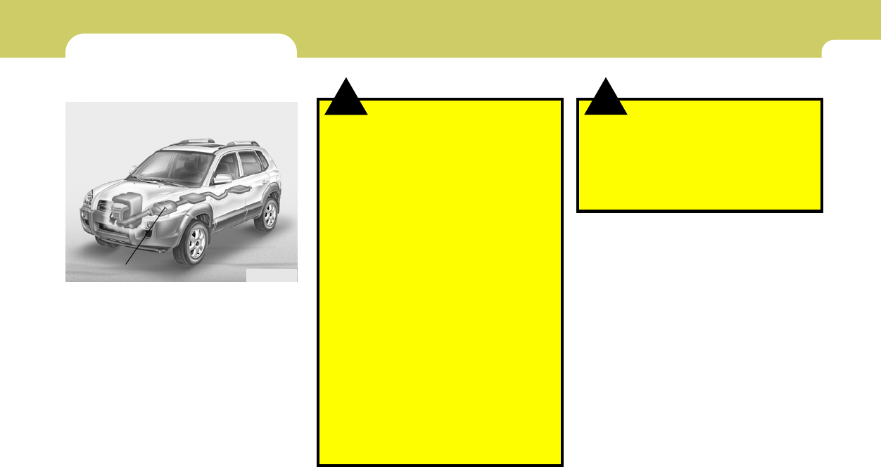
CLIMATE CONTROL AIR FILTER
(IN FRONT OF BLOWER UNIT)
B760A05E-AAT
(If installed)
The climate control air filter is located in front of
the blower unit behind the glove box.
It operates to decrease the amount of pollutants
entering the car.
To replace the climate control air filter, refer to
the page 6-17.
CAUTION:
oReplace the filter every 10,000 miles
(15,000 km) or once a year. If the car is
being driven in severe conditions such
as dusty, rough roads, more frequent
climate control air filter inspections and
changes are required.
oWhen the air flow rate is suddenly de-
creased, the system should be checked
by an authorized dealer.
!
B760A01E
Evaporator core
Filter
Heater core
Outside air
Inside air
Inside air
Blower fan
B980F01JM-GAT
Defrost Switch
When the "Defrost" button is pressed, the ( )
mode will be automatically selected and the air
will be discharged through the windshield de-
frost nozzle, side defroster nozzle and side
ventilator. To assist in defrosting, the air condi-
tioning will operate if ambient temperature is
higher than 2°C, and automatically turns off if the
ambient temperature drops below 2°C.
B980F01JM
1
FEATURES OF YOUR HYUNDAI
109109
109109109
STEREO SOUND SYSTEM
B750A02A-AAT
How Car Audio Works
AM broadcasts can be received at greater
distances than FM broadcasts. This is because
AM radio waves are transmitted at low frequen-
cies. These long, low frequency radio waves
can follow the curvature of the earth rather than
travelling straight out into the atmosphere. In
addition, they curve around obstructions so that
they can provide better signal coverage.
AM and FM radio signals are broadcast from
transmitter towers located around your city.
They are intercepted by the radio antenna on
your car. This signal is then received by the
radio and sent to your car speakers.
When a strong radio signal has reached your
vehicle, the precise engineering of your audio
system ensures the best possible quality repro-
duction. However, in some cases the signal
coming to your vehicle may not be strong and
clear. This can be due to factors such as the
distance from the radio station, closeness of
other strong radio stations or the presence of
buildings, bridges or other large obstructions in
the area.
FM broadcasts are transmitted at high frequen-
cies and do not bend to follow the earth's
surface. Because of this, FM broadcasts gen-
erally begin to fade at short distances from the
station. Also, FM signals are easily affected by
buildings, mountains, or other obstructions.
These can result in certain listening conditions
which might lead you to believe a problem exists
with your radio. The following conditions are
normal and do not indicate radio trouble:
Ionosphere
B750A02L
AM reception
Mountains
Buildings
Unobstructed
area
FM radio station
B750A03L
Ionosphere
FM reception
B750A01L
Obstructed area
Iron bridges
1
FEATURES OF YOUR HYUNDAI
110
oFading - As your car moves away from the
radio station, the signal will weaken and
sound will begin to fade. When this occurs,
we suggest that you select another stronger
station.
oFlutter/Static - Weak FM signals or large
obstructions between the transmitter and
your radio can disturb the signal causing
static or fluttering noises to occur. Reducing
the treble level may lessen this effect until the
disturbance clears.
oStation Swapping - As an FM signal weak-
ens, another more powerful signal near the
same frequency may begin to play. This is
because your radio is designed to lock onto
the clearest signal. If this occurs, select
another station with a stronger signal.
oMulti-Path Cancellation - Radio signals being
received from several directions can cause
distortion or fluttering. This can be caused by
a direct and reflected signal from the same
station, or by signals from two stations with
close frequencies. If this occurs, select
another station until the condition has passed.
B750A04L
B750A05L
!
B750B05Y-AAT
Using a cellular phone or a two-way radio
When a cellular phone is used inside the vehicle,
noise may be produced from the audio equip-
ment. This does not mean that something is
wrong with the audio equipment. In such a case,
use the cellular phone at a place as far as
possible from the audio equipment.
WARNING:
Hyundai recommends that you never use a
cell phone while driving. This could result
in loss of control, and an accident that may
cause death, serious injury, or property
damage. You must stop at a safe place to
use a cellular phone.
NOTE:
Some states and cities have regulations
prohibiting the use of cell phones while
driving. You should be aware of the specific
requirements in your area.
1
FEATURES OF YOUR HYUNDAI
111111
111111111
AUDIO SYSTEM
PA710E01JM-GAT
RADIO, SET UP, VOLUME CONTROL (PA 710S) (If installed)
A-200JMU
1. FM Selection Button
2. AM Selection Button
3. XM Selection Button
4. CD/AUX Selection Button
5. Automatic Channel Selection Button
6. Power ON/OFF
7. MUTE Button
8. SCAN Button
9. Information Display Button
10. SET UP Button
11. TUNE/ENTER Button
12. CAT(FLDR) Button
13. Preset Button
1
2
7
8
5
6
13
11
12
10
9
4
3
1
FEATURES OF YOUR HYUNDAI
112
1. FM Selection Button
Turns to FM mode and toggles FM1 and FM2
when the button is pressed each time.
2. AM Selection Button
Turns to AM mode, and toggles in the order of
AM1➟AM2➟···➟AM1···when the button is
pressed each time.
3. XM Selection Button
Turns to XM mode, and toggles in the order of
XM1➟XM2➟XM3➟···➟XM1··· when the button
is pressed each time.
4. CD/AUX Selection Button
If there is a cd in the CDP DECK it turns to CD
mode, and if a device is connected to AUX then
it toggles.
CD➟AUX➟CD··· when the button is pressed
each time.(It will not turn to AUX if the auxiliary
device is not connected)
5. Automatic Channel Selection Button
oWhen the [SEEK ]button is pressed, it
reduces the band frequency by 200khz to
automatically select channel. Stops at the
previous frequency if no channel is found.
oWhen the [SEEK ]button is pressed, it
increases the band frequency by 50khz to
automatically select channel. Stops at the
previous frequency if no channel is found.
6.Power ON/OFF & Volume Control
Button
Turns on/off the set when the IGNITION
SWITCH is on ACC or ON. If the button is turned
to the right, it increases the volume and left,
decreases the volume.
7. MUTE Button
Press to temporarily cut off the Sound.
8. SCAN Button
If this button is pressed, the frequencies will
become increased and receive the correspond-
ing broadcasts.
This function will play the frequencies for 5
seconds (XM MODE : 10 seconds) each and
find other broadcasts as the frequency in-
creases.
Press the button again when desiring to con-
tinue listening to the currently playing broad-
cast.
9. Information Display Button
Information Display function operation (Infor-
mation is displayed each time (the) Key is
pressed) : Pressing the Category ➟Channel
Name ➟Artist Name➟Song Title➟Category-
KEY for 3 seconds will display the correspond-
ing text then become restored.
Text Scroll operation
After pressing (the) Key, if the text to be dis-
played is longer than the LCD text line, then
rotating the Tune Knob will operate the Page up
function displaying 8 characters for 3 seconds
each - displays the maximum lines of text
supported by XM.
10. SET UP Button
Press this button to turn to the XMoption, SCROLL
and adjustment mode.
If no action is taken for 5 seconds after pressing
the button, it will return to the play mode.(After
entering SET UP mode, move between items
using the left, right and PUSH functions of the
TUNE button.)
The set up item changes from AUDIO adjust-
ment, TEXT SCROLL, XM setup.
1
FEATURES OF YOUR HYUNDAI
113113
113113113
11. TUNE/ENTER Button
Turn this button clockwise by one notch
to increase frequency by 0.05Mhz from current
frequency.
Turn this button counterclockwise by one notch
to decrease frequency by 0.05Mhz from cur-
rent frequency.
Press this button while holding SET UP button
to activate / inactivate the item to.
Select SET UP item using left and right function
of the Tune button.
Pressing the changes the BASS, MIDR- ANGE,
TREBLE, FADER and BALANCE TUNE mode.
The mode selected is shown on the display.
After selecting each mode, rotate the Audio
control knob clockwise or counterclockwise.
o BASS Control
To increase the BASS, rotate the knob clock-
wise, while to decrease the BASS, rotate the
knob counterclockwise.
o MID-RANGE Control
To increase the MID-RANGE, rotate the knob
clockwise, while to decrease the MID-RANGE,
rotate the knob counterclockwise.
o TREBLE Control
To increase the TREBLE, rotate the knob clock-
wise, while to decrease the TREBLE, rotate the
knob counterclockwise.
o FADER Control
Turn the control knob clockwise to emph- asize
rear speaker sound (front speaker sound will be
attenuated). When the control knob is turned
counterclockwise, front speaker sound will be
emphasized (rear speaker sound will be attenu-
ated).
o BALANCE Control
Rotate the knob clockwise to emphasize right
speaker sound (left speaker sound will be
attenuated). When the control knob is turned
counter clockwise, left speaker sound will be
emphasized (right speaker sound will be at-
tenuated).
12. CAT(FLDR) Button
Moves [CAT ] Button when Category Up
search operation.
oCategory is moved Up from the category
currently being received and Category Name
becomes displayed.
oIf the Enter Key is not pressed within 5
seconds, then the previous mode will be
restored.
oIf the Key is pressed while in the last Cat-
egory, then the first category will become
displayed and operation will be repeated.
oCorresponding category can be selected by
pressing ENTER.
Moves [CAT ] Button when Category Down
search operation.
oCategory is moved Down from the category
currently being received and Category Name
becomes displayed.
oIf the Enter Key is not pressed within 5
seconds, then the previous mode will be
restored.
oIf the [CAT ] Key is pressed while in the
first Category, then the last category will
become displayed and operation will be re-
peated.
oCorresponding category can be selected by
pressing ENTER.
13. Preset Button
Push [1]~[6] buttons less than 0.8 seconds to
play the channel saved in each button.
Push pre-set button for 0.8 seconds or longer
to save current channel to the respective button
with a beep.
1
FEATURES OF YOUR HYUNDAI
114
PA710F01JM-GAT
CD (PA 710S) (If installed)
A-201JMU
1. CD Loading Slot
2. CD Indicator
3. CD Eject Button
4. CD/AUX Selection Button
5. Automatic Track Selection Button
6. INFO Button
7. TUNE/ENTER Button
8. RANDOM Play Button
9. REPEAT Button
10. SCAN Play Button
11. FOLDER Button
1
3
5
8
7
11
2
6
4
9
10
1
FEATURES OF YOUR HYUNDAI
115115
115115115
1. CD Loading Slot
Please face printed side upward and gently
push in. When the ignition switch is on ACC or
ON and power is off, power is automatically
turned on if the CD is loaded. This CDP supports
both 8cm and 12 cm CDs. But if VCD, Data CD,
MP3 CD are loaded, "Er-6" message will appear
and CD will be ejected.
2. CD Indicator
When car ignition switch is ACC or ON and if the
CD is loaded, this indicator is lighted. If the CD
is ejected the light is turned off.
3. CD Eject Button
Push button to eject the CD during CD
playback. This button is enabled when ignition
switch is off.
4. CD/AUX Selection Button
If there is a cd in the CDP DECK it turns to CD
mode, and if a device is connected to AUX then
it toggles.
CD➟AUX➟CD··· when the button is pressed
each time.(It will not turn to AUX if the auxiliary
device is not connected)
5. Automatic Track Selection Button
oPush [SEEK ] button for less than 0.8
seconds to play from the beginning of cur-
rent song.
oPush [SEEK ] button for less than 0.8
seconds and press again within 1 seconds
to play the previous song.
oPush [SEEK ] button for 0.8 or longer to
initiate reverse direction high speed sound
search of current song.
oPush [SEEK ] button for less than 0.8
seconds to play the next song.
oPush [SEEK ] button for 0.8 or longer to
initiate high speed sound search of current
song.
6. INFO Button
Displays the information of the current CD
TRACK in the order of DISC TITLE ➟DISC
ARTIST➟TRACK TITLE➟ TRACK ARTIST
➟TOTAL TRACK➟ Play Screen ➟DISC
TITLE➟···.(not displayed if the information is not
available on the DISC.)
7. TUNE/ENTER Button
Turn this button clockwise to display songs
after current song.
Also, turn this button counterclockwise to dis-
play songs before current song.
To listen to the displayed song, press the button
to skip to the song and play.
Pressing the changes the BASS, MIDR- ANGE,
TREBLE, FADER and BALANCE TUNE mode.
The mode selected is shown on the display.
After selecting each mode, rotate the Audio
control knob clockwise or counterclockwise.
o BASS Control
To increase the BASS, rotate the knob clock-
wise, while to decrease the BASS, rotate the
knob counterclockwise.
o MID-RANGE Control
To increase the MID-RANGE, rotate the knob
clockwise, while to decrease the MID-RANGE,
rotate the knob counterclockwise.
o TREBLE Control
To increase the TREBLE, rotate the knob clock-
wise, while to decrease the TREBLE, rotate the
knob counterclockwise.
o FADER Control
Turn the control knob clockwise to emph- asize
rear speaker sound (front speaker sound will be
attenuated). When the control knob is turned
counterclockwise, front speaker sound will be
emphasized (rear speaker sound will be attenu-
ated).
1
FEATURES OF YOUR HYUNDAI
116
o BALANCE Control
Rotate the knob clockwise to emphasize right
speaker sound (left speaker sound will be
attenuated). When the control knob is turned
counter clockwise, left speaker sound will be
emphasized (right speaker sound will be at-
tenuated).
8. RANDOM Play Button
Turns on/off the randomization of the play list of
files in the currently played DISC.
To cancel the mode, press the key once again.
9. REPEAT Button
Repeats current song when the button is
pressed for less than 0.8 seconds.
Repeats the entire DISC when the button is
pressed for 0.8 seconds or longer.
10. SCAN Play Button
Plays first 10 seconds of each song in the DISC.
To cancel the mode, press the key once again.
11. FOLDER Button
Folder up/down operation.
oFolder is moved up or down from currently
playing and folder name becomes displayed.
oPress enter key to play the selected folder.
oIf the enter key is not pressed with in 5
seconds, then the previous folder name will
be displayed again.
1
FEATURES OF YOUR HYUNDAI
117117
117117117
PA760E01JM-GAT
RADIO, SET UP, VOLUME CONTROL (PA 760S) (If installed)
A-300JMU
1. FM Selection Button
2. AM Selection Button
3. XM Selection Button
4. CD/AUX Selection Button
5. Automatic Channel Selection Button
6. Power ON/OFF
7. MUTE Button
8. SCAN Button
9. Information Display Button
10. SET UP Button
11. TUNE/ENTER Button
12. CAT(FLDR) Button
13. Preset Button
1
2
7
8
5
6
13
11
12
10
9
4
3
1
FEATURES OF YOUR HYUNDAI
118
1. FM Selection Button
Turns to FM mode and toggles FM1 and FM2
when the button is pressed each time.
2. AM Selection Button
Turns to AM mode, and toggles in the order of
AM1➟AM2➟···➟AM1···when the button is
pressed each time.
3. XM Selection Button
Turns to XM mode, and toggles in the order of
XM1➟XM2➟XM3➟···➟XM1··· when the button
is pressed each time.
4. CD/AUX Selection Button
If there is a cd in the CDP DECK it turns to CD
mode, and if a device is connected to AUX then
it toggles.
CD➟AUX➟CD··· when the button is pressed
each time.(It will not turn to AUX if the auxiliary
device is not connected)
5. Automatic Channel Selection Button
oWhen the [SEEK ]button is pressed, it
reduces the band frequency by 200khz to
automatically select channel. Stops at the
previous frequency if no channel is found.
oWhen the [SEEK ]button is pressed, it
increases the band frequency by 50khz to
automatically select channel. Stops at the
previous frequency if no channel is found.
6.Power ON/OFF & Volume Control
Button
Turns on/off the set when the IGNITION
SWITCH is on ACC or ON. If the button is turned
to the right, it increases the volume and left,
decreases the volume.
7. MUTE Button
Press to temporarily cut off the Sound.
8. SCAN Button
If this button is pressed, the frequencies will
become increased and receive the correspond-
ing broadcasts.
This function will play the frequencies for 5
seconds (XM MODE : 10 seconds) each and
find other broadcasts as the frequency in-
creases.
Press the button again when desiring to con-
tinue listening to the currently playing broad-
cast.
9. Information Display Button
Information Display function operation (Infor-
mation is displayed each time (the) Key is
pressed) : Pressing the Category ➟Channel
Name ➟Artist Name➟Song Title➟Category-
KEY for 3 seconds will display the correspond-
ing text then become restored.
Text Scroll operation
After pressing (the) Key, if the text to be dis-
played is longer than the LCD text line, then
rotating the Tune Knob will operate the Page up
function displaying 8 characters for 3 seconds
each - displays the maximum lines of text
supported by XM.
10. SET UP Button
Press this button to turn to the XMoption, SCROLL
and adjustment mode.
If no action is taken for 5 seconds after pressing
the button, it will return to the play mode.(After
entering SET UP mode, move between items
using the left, right and PUSH functions of the
TUNE button.)
The set up item changes from AUDIO adjust-
ment, TEXT SCROLL, XM setup.
1
FEATURES OF YOUR HYUNDAI
119119
119119119
11. TUNE/ENTER Button
Turn this button clockwise by one notch to
increase frequency by 0.05Mhz from current
frequency.
Turn this button counterclockwise by one notch
to decrease frequency by 0.05Mhz from cur-
rent frequency.
Press this button while holding SET UP button
to activate / inactivate the item to.
Select SET UP item using left and right function
of the Tune button.
Pressing the changes the BASS, MIDR- ANGE,
TREBLE, FADER and BALANCE TUNE mode.
The mode selected is shown on the display.
After selecting each mode, rotate the Audio
control knob clockwise or counterclockwise.
o BASS Control
To increase the BASS, rotate the knob clock-
wise, while to decrease the BASS, rotate the
knob counterclockwise.
o MID-RANGE Control
To increase the MID-RANGE, rotate the knob
clockwise, while to decrease the MID-RANGE,
rotate the knob counterclockwise.
o TREBLE Control
To increase the TREBLE, rotate the knob clock-
wise, while to decrease the TREBLE, rotate the
knob counterclockwise.
o FADER Control
Turn the control knob clockwise to emph- asize
rear speaker sound (front speaker sound will be
attenuated). When the control knob is turned
counterclockwise, front speaker sound will be
emphasized (rear speaker sound will be attenu-
ated).
o BALANCE Control
Rotate the knob clockwise to emphasize right
speaker sound (left speaker sound will be
attenuated). When the control knob is turned
counter clockwise, left speaker sound will be
emphasized (right speaker sound will be at-
tenuated).
12. CAT(FLDR) Button
Moves [CAT ] Button when Category Up
search operation.
oCategory is moved Up from the category
currently being received and Category Name
becomes displayed.
oIf the Enter Key is not pressed within 5
seconds, then the previous mode will be
restored.
oIf the Key is pressed while in the last Cat-
egory, then the first category will become
displayed and operation will be repeated.
oCorresponding category can be selected by
pressing ENTER.
Moves [CAT ] Button when Category Down
search operation.
oCategory is moved Down from the category
currently being received and Category Name
becomes displayed.
oIf the Enter Key is not pressed within 5
seconds, then the previous mode will be
restored.
oIf the [CAT ] Key is pressed while in the
first Category, then the last category will
become displayed and operation will be re-
peated.
oCorresponding category can be selected by
pressing ENTER.
13. Preset Button
Push [1]~[6] buttons less than 0.8 seconds to
play the channel saved in each button.
Push pre-set button for 0.8 seconds or longer
to save current channel to the respective button
with a beep.
1
FEATURES OF YOUR HYUNDAI
120
PA760F01JM-GAT
CDC (PA 760S) (If Installed)
A-301JMU
1. CD Loading Slot
2. CD Eject Button
3. LOAD Button
4. CD/AUX Selection Button
5. Automatic Track Selection Button
6. INFO Button
7. TUNE/ENTER Button
8. RANDOM Play Button
9. REPEAT Button
10. DISC Selection Button
11. SCAN Play Button
12. FOLDER Button
1
2
5
8
7
12
3
6
4
9
10
11
1
FEATURES OF YOUR HYUNDAI
121121
121121121
1. CD Loading Slot
Please face printed side upward and gently
push in. When the ignition switch is on ACC or
ON and power is off, power is automatically
turned on if the CD is loaded. This CDP supports
both 8cm and 12 cm CDs. But if VCD, Data CD,
MP3 CD are loaded, "Er-6" message will appear
and CD will be ejected.
2. CD Eject Button
Push button to eject the CD during CD
playback. This button is enabled when ignition
switch is off.
3. CD LOAD Button
Push [LOAD] button to load CDs to available
CDC deck (from 1~6). Push [LOAD] button for
more than 2 seconds to load into all available
decks.
The last CD will play. 10 seconds idle status will
disable loading process.
4. CD/AUX Selection Button
If the auxiliary device is connected, it turns to
AUX MODE to play the sound from the auxiliary
player.
If no auxiliary device is connected, it displays
""NO MEDIA"" for 5 seconds and returns to the
previous mode."
5. Automatic Track Selection Button
oPush [SEEK ] button for less than 0.8
seconds to play from the beginning of cur-
rent song.
oPush [SEEK ] button for less than 0.8
seconds and press again within 1 seconds
to play the previous song.
oPush [SEEK ] button for 0.8 or longer to
initiate reverse direction high speed sound
search of current song.
oPush [SEEK ] button for less than 0.8
seconds to play the next song.
oPush [SEEK ] button for 0.8 or longer to
initiate high speed sound search of current
song.
6. INFO Button
Displays the information of the current CD
TRACK in the order of DISC TITLE ➟DISC
ARTIST➟TRACK TITLE➟ TRACK
ARTIST➟TOTAL TRACK➟Play Screen ➟DISC
TITLE➟···.(not displayed if the information is not
available on the DISC.)
7. TUNE/ENTER Button
Turn this button clockwise to display songs
after current song.
Also, turn this button counterclockwise to dis-
play songs before current song.
To listen to the displayed song, press the button
to skip to the song and play.
Pressing the changes the BASS, MIDR- ANGE,
TREBLE, FADER and BALANCE TUNE mode.
The mode selected is shown on the display.
After selecting each mode, rotate the Audio
control knob clockwise or counterclockwise.
o BASS Control
To increase the BASS, rotate the knob clock-
wise, while to decrease the BASS, rotate the
knob counterclockwise.
o MID-RANGE Control
To increase the MID-RANGE, rotate the knob
clockwise, while to decrease the MID-RANGE,
rotate the knob counterclockwise.
o TREBLE Control
To increase the TREBLE, rotate the knob clock-
wise, while to decrease the TREBLE, rotate the
knob counterclockwise.
o FADER Control
Turn the control knob clockwise to emph- asize
rear speaker sound (front speaker sound will be
attenuated). When the control knob is turned
counterclockwise, front speaker sound will be
emphasized (rear speaker sound will be attenu-
ated).
1
FEATURES OF YOUR HYUNDAI
122
o BALANCE Control
Rotate the knob clockwise to emphasize right
speaker sound (left speaker sound will be
attenuated). When the control knob is turned
counter clockwise, left speaker sound will be
emphasized (right speaker sound will be at-
tenuated).
8. RANDOM Play Button
Turns on/off the randomization of the play list of
files in the currently played DISC.
To cancel the mode, press the key once again.
9. REPEAT Button
Repeats current song when the button is
pressed for less than 0.8 seconds.
Repeats the entire DISC when the button is
pressed for 0.8 seconds or longer.
10. DISC Selection Button
o[DISC ] Change Button
Changes disc to the previous disc.
o[DISC ] Change Button
Changes disc to the next disc.
11. SCAN Play Button
Plays first 10 seconds of each song in the DISC.
To cancel the mode, press the key once again.
12. FOLDER Button
Folder up/down operation.
oFolder is moved up or down from currently
playing and folder name becomes displayed.
oPress enter key to play the selected folder.
oIf the enter key is not pressed with in 5
seconds, then the previous folder name will
be displayed again.
1
FEATURES OF YOUR HYUNDAI
123123
123123123
INDICATION
Er2
Er3
Er6
Er8
HHH
no CD
B890A01Y-AAT
AUDIO FAULT CODE
If you see any error indication in the display while using the system in the CD or Tape mode, find the cause in the chart below. If you cannot clear the
error indication, take the car to your Hyundai dealer.
SOLUTION
After resetting the audio system, push the eject button.
If disc is not ejected, consult your Hyundai dealer.
Make sure the disc is not scratched or damaged.
Press the eject button and pull out the disc.
Then insert a normal CD disc.
Check if the disc is inserted correctly in the CD player.
Make sure the disc is not scratched or damaged.
After resetting the audio system, push the eject button.
If tape does not eject, consult your Hyundai dealer.
Fault code will reset automatically when the temperature returns to normal.
Insert disc in magazine or insert CD magazine in the auto changer.
CAUSE
CD DECK MECHANICAL ERROR
(EJECT ERROR, LOADING ERROR)
FOCUS ERROR
DATA READ ERROR
DISC ERROR
TAPE DECK ERROR
TAPE EJECT ERROR
TEMPERATURE IS TOO HIGH
NO DISC IN MAGAZINE
NO CD MAGAZINE IN THE AUTO CHANGER
1
FEATURES OF YOUR HYUNDAI
124
CARE OF CASSETTE TAPESCARE OF DISCS
B850A02L
B850A02F-AAT
Proper Handling
Storage
When not in use, place your discs in their
individual case and store them in a cool place
away from the sun, heat, and dust.
Do not grip or pull out the disc with your hand
while the disc is being pulled into the unit by the
self loading mechanism.
Keep Your Discs Clean
Handle your disc as shown. Do not drop the
disc. Hold the disc so you will not leave finger-
prints on the surface. If the surface is scratched,
it may cause the pickup to skip signal tracks. Do
not affix tape, paper, or gummed labels on the
disc. Do not write on the disc.
Damaged Disc
Do not attempt to play damaged, warped or
cracked discs. These could severely damage
the playback mechanism.
Fingerprints, dust, or soil on the surface of a disc
could cause the pickup to skip signal tracks.
Wipe the surface clean with a clean soft cloth.
If the surface is heavily soiled, dampen a clean
soft cloth in a solution of mild neutral detergent
to wipe it clean. See drawing.
B860A01A-AAT
Proper care of your cassette tapes will extend
the tape life and increase your listening enjoy-
ment. Always protect your tapes and cassette
cases from direct sunlight, severely cold and
dusty conditions. When not in use, cassettes
should always be stored in the original protec-
tive cassette case. When the vehicle is very hot
or cold, allow the interior temperature to become
more comfortable before listening to your cas-
settes.
B850A01L
B860A01L
1
FEATURES OF YOUR HYUNDAI
125125
125125125
oBe sure that the cassette label is not loose
or peeling off or tape ejection may be difficult.
oNever touch or soil the actual audio tape
surfaces.
oKeep all magnetized objects, such as elec-
tric motors, speakers or transformers away
from your cassette tapes and tape player
unit.
Head
Cotton applicator
B860A01JM
B860A02L
oThe playback head, capstan and pinch roll-
ers will develop a coating of tape residue that
can result in deterioration of sound quality,
such as a wavering sound. They should be
cleaned monthly using a commercially avail-
able head cleaning tape or special solution
available from audio specialty shops. Follow
the supplier's directions carefully and never
oil any part of the tape player unit.
oAlways be sure that the tape is tightly wound
on its reel before inserting in the player.
Rotate a pencil in the drive sprockets to wind
up any slack.
oNever leave a cassette inserted in the player
when not being played. This could damage
the tape player unit and the cassette tape.
oWe strongly recommend against the use of
tapes longer than C-60 (60 minutes total).
Tapes such as C-120 or C-180 are very thin
and do not perform as well in the automotive
environment.
oStore cassettes in a cool, dry place with the
open side facing down to prevent dust from
settling in the cassette body.
oAvoid repeated fast reverse usage to replay
one given tune or tape section. This can
cause poor tape winding to occur, and even-
tually cause excessive internal drag and
poor audio quality in the cassette. If this
occurs, it can sometimes be corrected by
fast winding the tape from end to end several
times.If this does not correct the problem,
do not continue to use the tape in your
vehicle.
1
FEATURES OF YOUR HYUNDAI
126
CAUTION:
oBe sure to remove the antenna before
washing the car in an automatic car
wash or it may be damaged.
oBefore entering a place with a low height
clearance, be sure to adjust the roof
antenna low.
oIn some vehicles, the antenna can be
folded into only front position.
oWhen reinstalling your antenna, it is
important that it is fully tightened to
ensure proper reception.
!
ANTENNA
B870D02JM-U
B870D02JM-AAT
Roof Antenna
Your car uses a roof antenna to receive both AM
and FM broadcast signals.
This antenna is a removable type. To remove
the antenna, turn the antenna counterclock-
wise. To install the antenna, turn the antenna
clockwise.
NOTE:
Look at a tape before you insert it. If the tape
is loose, tighten it by turning one of the
hubs with a pencil or your finger. If the label
is peeling off, do not put it in the drive
mechanism.
Do not leave tapes sitting where they are
exposed to hot, warm, or high humidity,
such as on top of the dashboard or in the
player. If a tape is excessively hot or cold, let
it reach a moderate temperature before
putting it in the player.
B860A03L
Type AType B
DRIVING YOUR HYUNDAI
2
Engine Exhaust Can Be Dangerous!............................ 2-2
Before Starting the Engine............................................2-4
Gebruikershandleiding.com neemt misbruik van zijn services uitermate serieus. U kunt hieronder aangeven waarom deze vraag ongepast is. Wij controleren de vraag en zonodig wordt deze verwijderd.
Product:
Spelregels forum
Om tot zinvolle vragen te komen hanteren wij de volgende spelregels:
lees eerst de handleiding door;
controleer of uw vraag al eerder door iemand anders is gesteld;
probeer uw vraag zo duidelijk mogelijk te stellen;
heeft u een probleem en al geprobeerd om dit op te lossen, vermeld dit erbij aub;
heeft u een oplossing gekregen van een bezoeker dan horen wij dat graag in dit forum;
wilt u een reactie geven op een vraag of antwoord, gebruik dan niet dit formulier maar klik op de knop 'reageer op deze vraag';
uw vraag wordt direct op de website gezet; vermijd daarom persoonlijke gegevens in te vullen;
Belangrijk! Als er een antwoord wordt gegeven op uw vraag, dan is het voor de gever van het antwoord nuttig om te weten als u er wel (of niet) mee geholpen bent! Wij vragen u dus ook te reageren op een antwoord.
Belangrijk! Antwoorden worden ook per e-mail naar abonnees gestuurd. Laat uw emailadres achter op deze site, zodat u op de hoogte blijft. U krijgt dan ook andere vragen en antwoorden te zien.
Abonneren
Abonneer u voor het ontvangen van emails voor uw Hyundai Tucson 2008 bij:
nieuwe vragen en antwoorden
nieuwe handleidingen
U ontvangt een email met instructies om u voor één of beide opties in te schrijven.
Ontvang uw handleiding per email
Vul uw emailadres in en ontvang de handleiding van Hyundai Tucson 2008 in de taal/talen: Engels als bijlage per email.
De handleiding is 11,54 mb groot.
U ontvangt de handleiding per email binnen enkele minuten. Als u geen email heeft ontvangen, dan heeft u waarschijnlijk een verkeerd emailadres ingevuld of is uw mailbox te vol. Daarnaast kan het zijn dat uw internetprovider een maximum heeft aan de grootte per email. Omdat hier een handleiding wordt meegestuurd, kan het voorkomen dat de email groter is dan toegestaan bij uw provider.
Stel vragen via chat aan uw handleiding
Stel uw vraag over deze PDF
Uw handleiding is per email verstuurd. Controleer uw email
Als u niet binnen een kwartier uw email met handleiding ontvangen heeft, kan het zijn dat u een verkeerd emailadres heeft ingevuld of dat uw emailprovider een maximum grootte per email heeft ingesteld die kleiner is dan de grootte van de handleiding.
Er is een email naar u verstuurd om uw inschrijving definitief te maken.
Controleer uw email en volg de aanwijzingen op om uw inschrijving definitief te maken
U heeft geen emailadres opgegeven
Als u de handleiding per email wilt ontvangen, vul dan een geldig emailadres in.
Uw vraag is op deze pagina toegevoegd
Wilt u een email ontvangen bij een antwoord en/of nieuwe vragen? Vul dan hier uw emailadres in.