Maintenance under Severe Usage Conditions............. 5-6
Explanation of Scheduled Maintenance Items..............5-7
California Perchlorate Notice...................................... 5-10
VEHICLE MAINTENANCE REQUIREMENTS
5
5
VEHICLE MAINTENANCE REQUIREMENTS
2
F010C01A-AAT
Specified Scheduled Procedures
These are the procedures such as inspec-
tions, adjustments and replacements that
are listed in the maintenance charts start-
ing on page 5-4. These procedures must
be performed at the intervals shown in the
maintenance schedule to assure that your
warranty remains in effect. Although it is
strongly recommended that they be per-
formed by the trained technicians at your
Hyundai dealer, these procedures may be
performed at any qualified service facility.
It is suggested that genuine Hyundai ser-
vice parts be used for any required repairs
or replacements. Other parts of equivalent
quality such as engine oil, engine coolant,
manual or auto transaxle oil, brake fluid
and so on which are not supplied by
Hyundai Motor Company or its distributor
may be used without affecting your war-
ranty coverage but you should always be
sure these are equivalent to the quality of
the original Hyundai parts. Your Owner's
Handbook provides further information
about your warranty coverage.
F010A01A-AAT
Service Requirements
To ensure that you receive the greatest
number of miles of satisfying operation
from your Hyundai, certain maintenance
procedures must be performed. Although
careful design and engineering have re-
duced these to a minimum, those that are
required are of the utmost importance.
It is your responsibility to have these main-
tenance procedures performed to comply
with the terms of the warranties covering
your new Hyundai. The Owner's Hand-
book supplied with your new vehicle pro-
vides further information about these war-
ranties.
F010B01A-AAT
Maintenance Requirements
The maintenance required for your
Hyundai can be divided into three main
areas:
o Specified scheduled procedures
o General checks
o Do-it-yourself maintenance
MAINTENANCE INTERVALS
5
VEHICLE MAINTENANCE REQUIREMENTS
3
SCHEDULED MAINTE-
NANCE REQUIREMENTS
F020A02Y-AAT
oInspection should be performed any
time a malfunction is experienced or
suspected.
oReceipts for all emission control system
services should be retained to demon-
strate compliance with conditions of the
emissions system warranty.
oAfter 120 months or 150,000 miles
(240,000 km), continue to follow the
prescribed maintenance intervals.
oFor severe usage maintenance require-
ments, see page 5-6 of this section.
F010D02A-AAT
General Checks
These are the regular checks you should
perform when you drive your Hyundai or
you fill the fuel tank. A list of these items will
be found on page 6-5.
F010E01A-AAT
Do-It-Yourself Maintenance
If you are mechanically inclined, own a few
tools that are required and want to take the
time to do so, you can inspect and service
a number of items. For more information
about doing it yourself, see Section 6.
F010F01A-AAT
A Few Tips
oWhenever you have your Hyundai ser-
viced, keep copies of the service records
in your glovebox. This will help ensure
that you can document that the required
procedures have been performed to
keep your warranties in effect. This is
especially important when service is
not performed by an authorized
Hyundai dealer.
oIf you choose to do your own mainte-
nance and repairs, you may find it
helpful to have an official Hyundai Shop
Manual. A copy of this publication may
be purchased at your Hyundai dealer's
parts department.
5
VEHICLE MAINTENANCE REQUIREMENTS
4
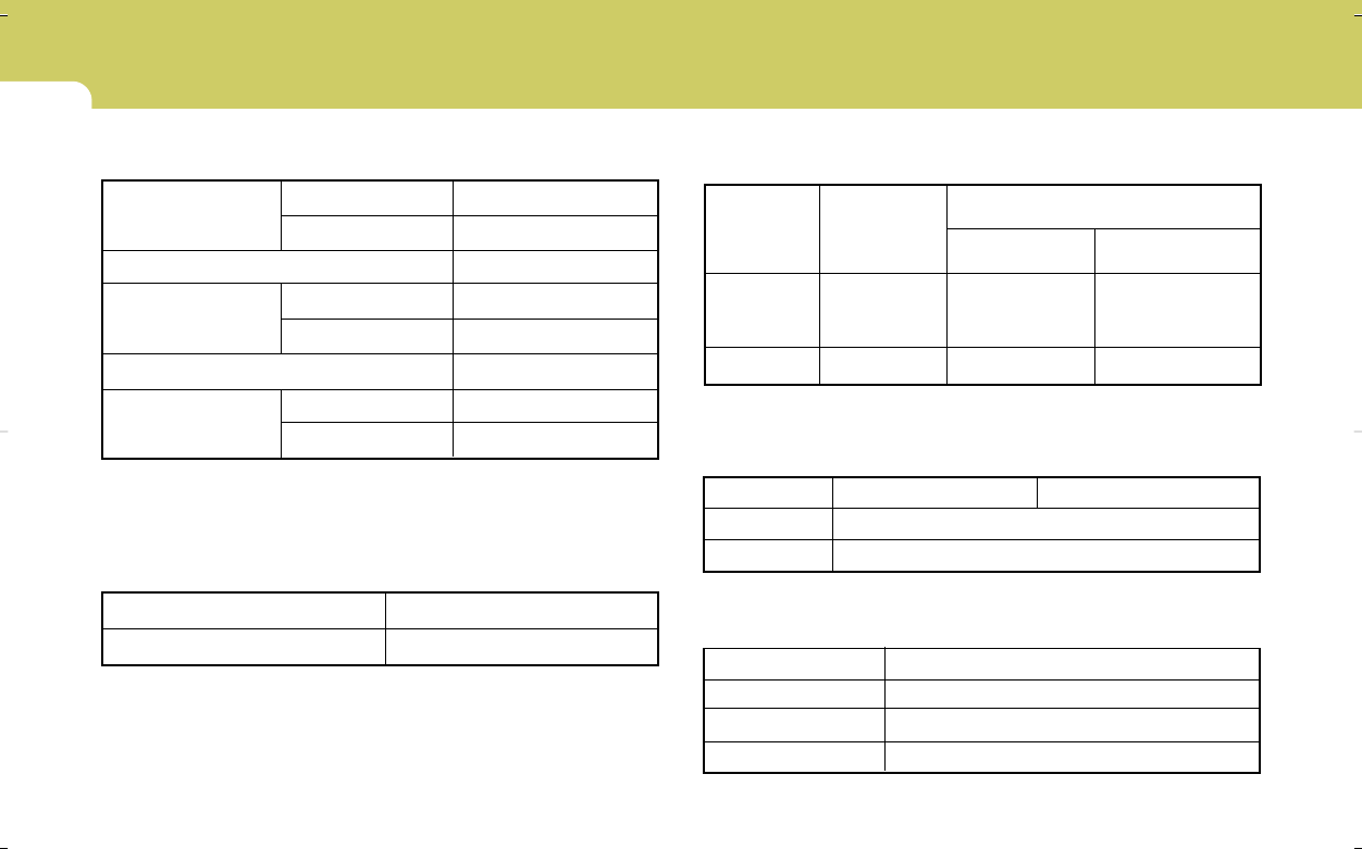
SCHEDULED MAINTENANCE
F030B02O-AAT
R :Replace I : Inspect and, after Inspection, clean, adjust, repair or replace if necessary.
DESCRIPTION
EMISSION CONTROL ITEMS
ENGINE OIL AND FILTER
FUEL FILTER
FUEL LINES, FUEL HOSES AND CONNECTIONS
VACUUM HOSES
CRANKCASE VENTILATION HOSE
VAPOR HOSE AND FUEL FILLER CAP
AIR CLEANER FILTER
FUEL TANK AIR FILTER
SPARK PLUGS (IRIDIUM COATED) *
1
VALVE CLEARANCESee Note *
2
No.
1
2
3
4
5
6
7
8
9
10
MILES X 1000
KILOMETERS X 1000
MONTHS
7.5
12
6
R
I
15
24
12
R
I
I
I
22.5
36
18
R
I
30
48
24
R
I
I
I
R
R
37.5
60
30
R
I
45
72
36
R
I
I
I
52.5
84
42
R
I
I
60
96
48
R
R
I
I
I
R
R
67.5
108
54
R
I
75
120
60
R
I
I
I
82.5
132
66
R
I
90
144
72
R
I
I
I
R
R
97.5
156
78
R
I
R
105
168
84
R
I
I
I
I
112.5
180
90
R
I
120
192
96
R
R
I
I
I
R
R
127.5
204
102
R
I
135
216
108
R
I
I
I
142.5
228
114
R
I
150
240
120
R
I
I
I
R
R
F030A01A-AAT
The following maintenance services must be performed to ensure good emission control and performance. Keep receipts for all vehicle
emission services to protect your warranty. Where both mileage and time are shown, the frequency of service is determined by whichever
occurs first.
2.7 ENGINE
3.3 ENGINE
EVERY 7,500 MILES (12,000 KM) OR 12 MONTHS : "R"
INSPECT AND ADJUST EVERY 60,000 MILES (96,000 KM) OR 48 MONTHS
Note :*1. Spark plugs should be long-reach type when replaced (2.7 only)
*2. Inspect for excessive tappet noise and/or engine vibration and adjust if necessary.
5
VEHICLE MAINTENANCE REQUIREMENTS
5
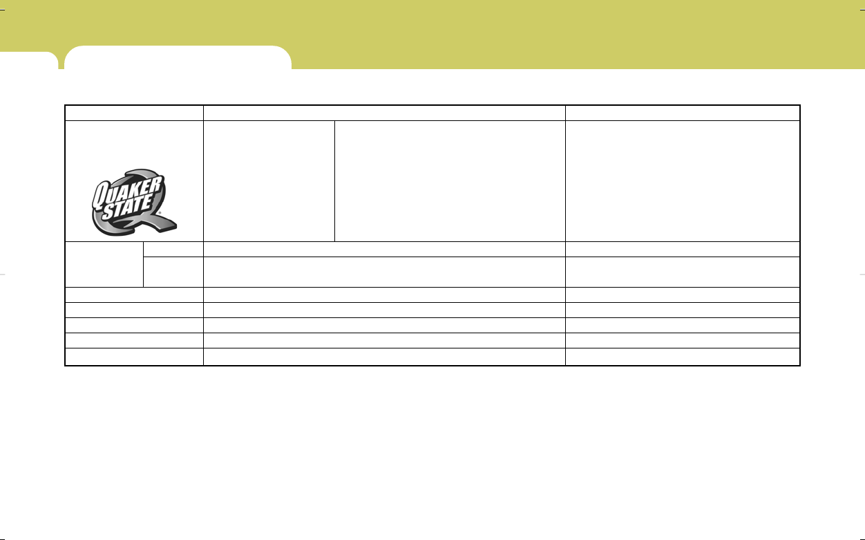
Note :*1.For the first time replace the coolant at 60,000 miles (96,000 km) or 60 months. After that replace it every 30,000 miles (48,000 km) or 24 months.
*2.Inspect every 37,500 miles (60,000 km) replace every 75,000 miles (120,000 km) or 60 months
*3.For every 12 months or 10,000 miles (15,000 km), whichever occurs first: "R"
F030C01CM-AAT
R : Replace I : Inspect and, after inspection, clean, adjust, repair or replace if necessary
GENERAL ITEMS
DRIVE BELT
COOLANT
TIMING BELT (ONLY 2.7 V6)
MANUAL TRANSAXLE FLUID
AUTOMATIC TRANSAXLE FLUID
BRAKE FLUID
BRAKE HOSES AND LINES
PARKING BRAKE
BRAKE PADS, CALIPERS AND ROTORS (FRONT, REAR)
EXHAUST PIPE AND MUFFLER
SUSPENSION MOUNTING BOLTS
STEERING GEAR BOX, LINKAGE & BOOTS / LOWER ARM
BALL JOINT
POWER STEERING PUMP, BELT AND HOSES
DRIVESHAFTS AND BOOTS
AIR CONDITIONING REFRIGERANT
CLIMATE CONTROL AIR FILTER
(FOR EVAPORATOR AND BLOWER UNIT)
TRANSFER CASE OIL (AWD)
REAR AXLE OIL (AWD)
PROPELLAR SHAFT CLEAN, BOLT RETIGHTEN (AWD)
1
2
3
4
5
6
7
8
9
10
11
12
13
14
15
16
17
18
19
No.DESCRIPTION
MILES X 1000
KILOMETERS X 1000
MONTHS
2.7 V6 (ALT, P/STR'G, A/CON)
3.3 V6 (ALT, P/STR'G, A/CON)
7.5
12
6
I
I
15
24
12
I
I
I
I
I
I
I
I
I
22.5
36
18
I
I
30
48
24
I
I
I
I
I
I
I
I
I
I
I
I
I
I
I
I
I
37.5
60
30
I
I
45
72
36
I
I
I
I
I
I
I
I
I
52.5
84
42
I
I
60
96
48
I
I
I
I
I
I
I
I
I
I
I
I
I
I
I
I
I
67.5
108
54
I
I
75
120
60
I
I
I
I
I
I
I
I
R
I
82.5
132
66
I
I
90
144
72
I
I
I
I
I
I
I
I
I
I
I
I
I
I
I
I
I
97.5
156
78
I
I
105
168
84
R
I
I
I
I
I
I
I
I
112.5
180
90
I
I
120
192
96
I
I
I
I
I
I
I
I
I
I
I
I
I
I
I
I
I
127.5
204
102
I
I
135
216
108
I
I
I
I
I
I
I
I
I
142.5
228
114
I
I
150
240
120
I
I
I
I
I
I
I
I
I
I
I
I
I
I
I
I
I
See Note *
1
See Note *
2
See Note *
3
5
VEHICLE MAINTENANCE REQUIREMENTS
6
MAINTENANCE UNDER SEVERE USAGE
CONDITIONS
F040A01CM-AAT
The following items must be serviced more frequently on cars normally used under severe driving conditions. Refer to the chart below
for the appropriate maintenance intervals.
R : Replace I : Inspect and, after inspection, clean, adjust, repair or replace if necessary
*1. Transfer case Oil and Rear Axle Oil should be changed anytime they have been submerged in water.
ik heb net een santa fe gekocht , praCHT AUTO , IK BEN EEN ROKER EN WIL DE ASBAK LEGEN MAAR IK KRIJG DE ASBAK ER NIET UIT , HOE MOET BIK DAT DOEN ?
Gesteld op 31-5-2023 om 20:24
Hallo, sinds enige tijd gaat er een lampje op mijn dashbord aan en uit. Ik heb een Hyundai Santa Fe 4x4 uit 2007. Het gaat om een lampje (links op dashbord) van een geel oliekannetje met golfjes (water) eronder. Iemand enig idee wat dit betekend? Ik heb alle boeken en gebruiksaanwijzingen erop nageslagen, maar kan dit symbool nergens terug vinden (ook niet bij andere modellen). Alvast dank! Groetjes Debby
Gesteld op 25-3-2021 om 15:23
Gebruikershandleiding.com neemt misbruik van zijn services uitermate serieus. U kunt hieronder aangeven waarom deze vraag ongepast is. Wij controleren de vraag en zonodig wordt deze verwijderd.
Product:
Spelregels forum
Om tot zinvolle vragen te komen hanteren wij de volgende spelregels:
lees eerst de handleiding door;
controleer of uw vraag al eerder door iemand anders is gesteld;
probeer uw vraag zo duidelijk mogelijk te stellen;
heeft u een probleem en al geprobeerd om dit op te lossen, vermeld dit erbij aub;
heeft u een oplossing gekregen van een bezoeker dan horen wij dat graag in dit forum;
wilt u een reactie geven op een vraag of antwoord, gebruik dan niet dit formulier maar klik op de knop 'reageer op deze vraag';
uw vraag wordt direct op de website gezet; vermijd daarom persoonlijke gegevens in te vullen;
Belangrijk! Als er een antwoord wordt gegeven op uw vraag, dan is het voor de gever van het antwoord nuttig om te weten als u er wel (of niet) mee geholpen bent! Wij vragen u dus ook te reageren op een antwoord.
Belangrijk! Antwoorden worden ook per e-mail naar abonnees gestuurd. Laat uw emailadres achter op deze site, zodat u op de hoogte blijft. U krijgt dan ook andere vragen en antwoorden te zien.
Abonneren
Abonneer u voor het ontvangen van emails voor uw Hyundai Santa Fe 2007 bij:
nieuwe vragen en antwoorden
nieuwe handleidingen
U ontvangt een email met instructies om u voor één of beide opties in te schrijven.
Ontvang uw handleiding per email
Vul uw emailadres in en ontvang de handleiding van Hyundai Santa Fe 2007 in de taal/talen: Engels als bijlage per email.
De handleiding is 12,24 mb groot.
U ontvangt de handleiding per email binnen enkele minuten. Als u geen email heeft ontvangen, dan heeft u waarschijnlijk een verkeerd emailadres ingevuld of is uw mailbox te vol. Daarnaast kan het zijn dat uw internetprovider een maximum heeft aan de grootte per email. Omdat hier een handleiding wordt meegestuurd, kan het voorkomen dat de email groter is dan toegestaan bij uw provider.
Stel vragen via chat aan uw handleiding
Stel uw vraag over deze PDF
Uw handleiding is per email verstuurd. Controleer uw email
Als u niet binnen een kwartier uw email met handleiding ontvangen heeft, kan het zijn dat u een verkeerd emailadres heeft ingevuld of dat uw emailprovider een maximum grootte per email heeft ingesteld die kleiner is dan de grootte van de handleiding.
Er is een email naar u verstuurd om uw inschrijving definitief te maken.
Controleer uw email en volg de aanwijzingen op om uw inschrijving definitief te maken
U heeft geen emailadres opgegeven
Als u de handleiding per email wilt ontvangen, vul dan een geldig emailadres in.
Uw vraag is op deze pagina toegevoegd
Wilt u een email ontvangen bij een antwoord en/of nieuwe vragen? Vul dan hier uw emailadres in.