


-
De braaiknop knippert en de robot verlaat het station niet Gesteld op 25-7-2024 om 19:58
Reageer op deze vraag Misbruik melden -
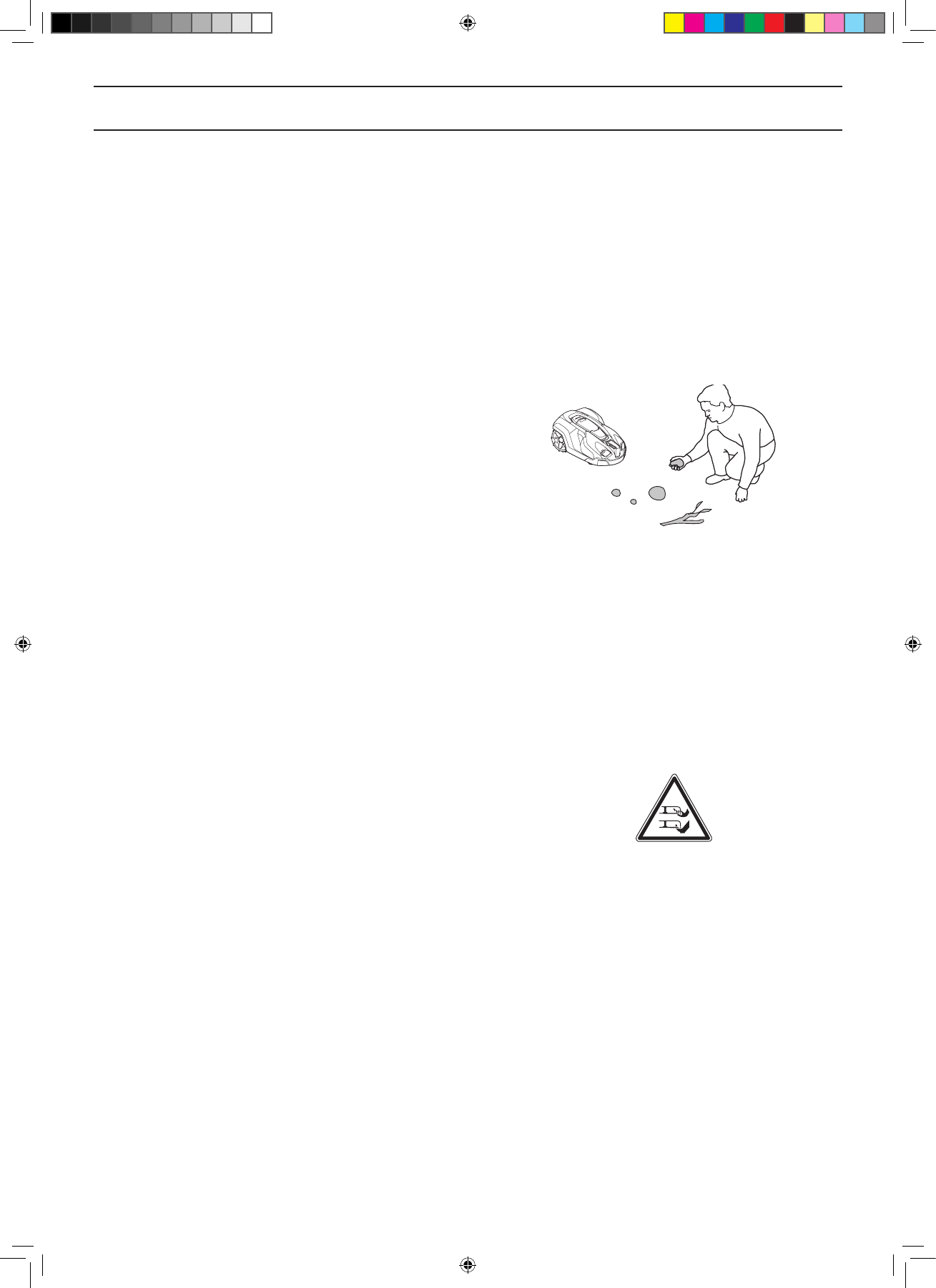
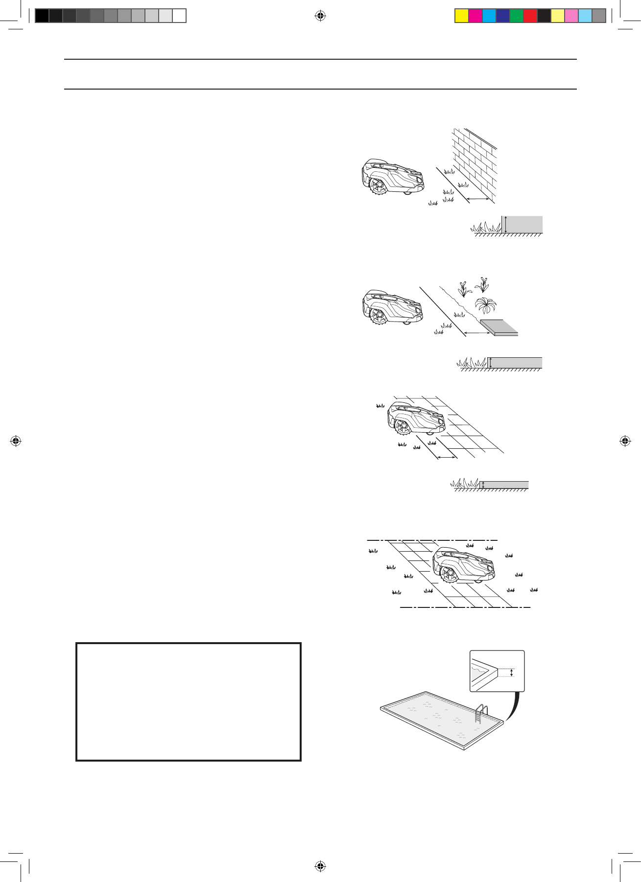
De 430X heeft over zijn draad gereden, het zwembad in. Dat heeft hij nog nooit gedaan, hoe kan hij dit plots wel doen? Gesteld op 2-2-2024 om 13:46
Reageer op deze vraag Misbruik melden -
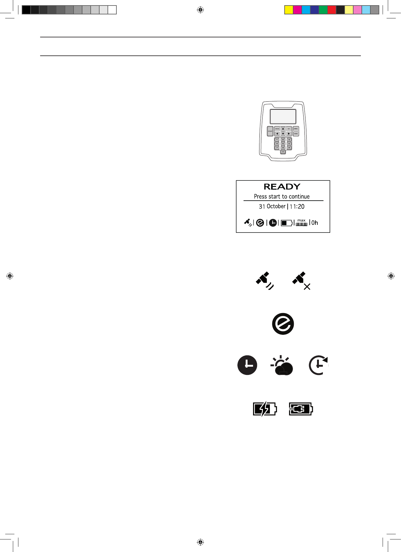
Ik zie helemaal geen lampje in het laad station branden. Gesteld op 14-11-2023 om 11:51
Reageer op deze vraag Misbruik melden-
Dan staat er geen netspanning op Geantwoord op 14-11-2023 om 11:53
Waardeer dit antwoord Misbruik melden
-
-
Waarschijnlijk trafo kapot. Geantwoord op 14-11-2023 om 14:28
Waardeer dit antwoord Misbruik melden -
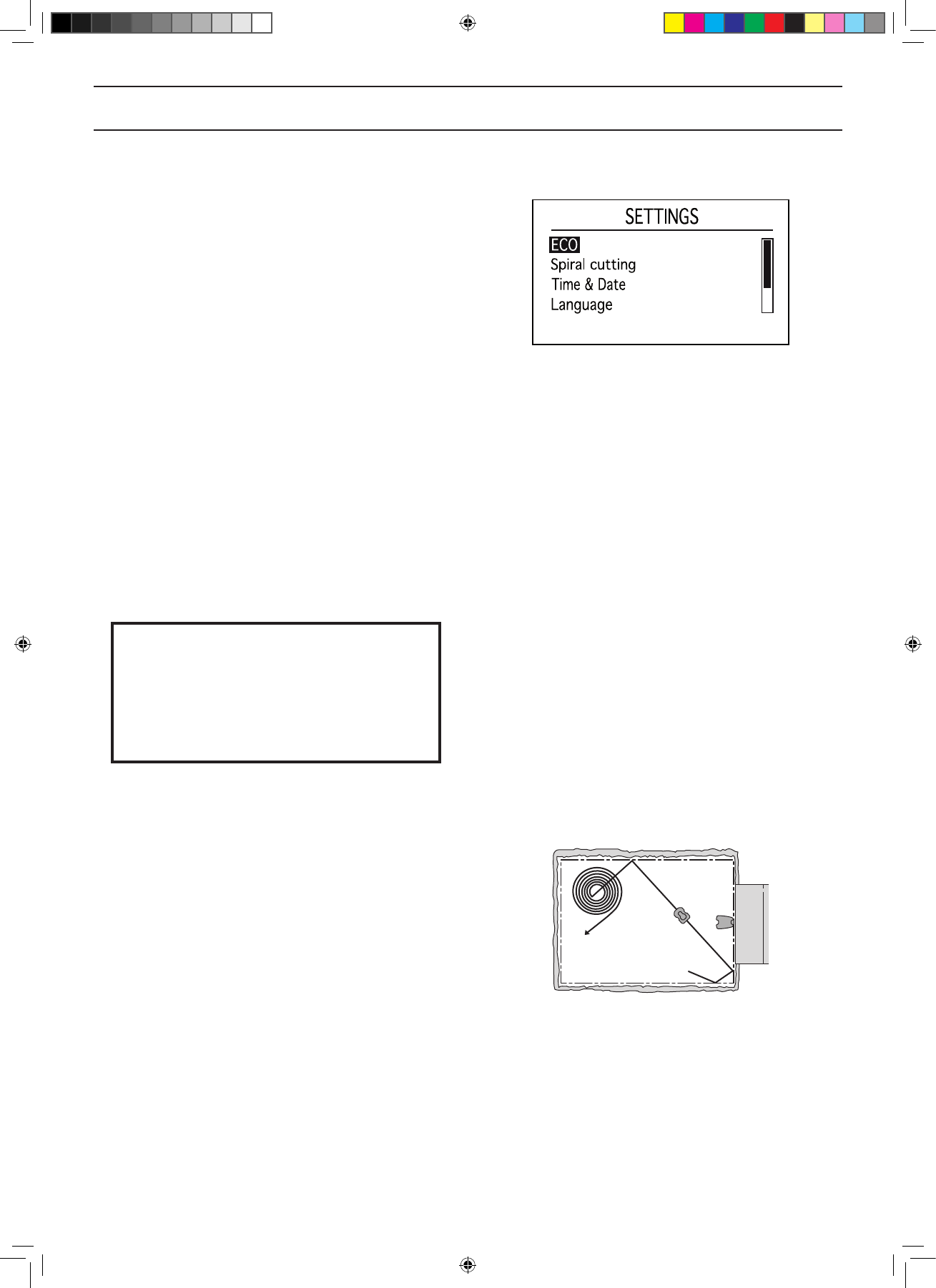
Hoe kan ik de maaier instellen zodat hij een bijgebied gaat maaien? Gesteld op 1-10-2023 om 13:49
Reageer op deze vraag Misbruik melden -
430 X Ik geplaatst in het laadstation maar er kom geen display er is 220 Volt aanwezig Gesteld op 3-4-2023 om 19:38
Reageer op deze vraag Misbruik melden -
Mijn husquarna maait een gedeelte van de tuin niet meer. Wanneer ik de maaier daar neer zet geeft hij aan “ Buiten maaigebied”. Dit is nadat de maaier opnieuw geïnstalleerd is na de winter.
Reageer op deze vraag Misbruik melden
Weet iemand wat er fout is gegaan Gesteld op 23-3-2023 om 08:05
-
Ik heb de robot zojuist aangesloten,maar geeft aan op de app geen verbinding te hebben. Gesteld op 17-3-2023 om 16:02
Reageer op deze vraag Misbruik melden -
De maaier geeft melding : Botsen Actief en hij gaat niet door!
Reageer op deze vraag Misbruik melden
Hoe kan ik hem verder laten maaien? Gesteld op 11-4-2022 om 15:53 -
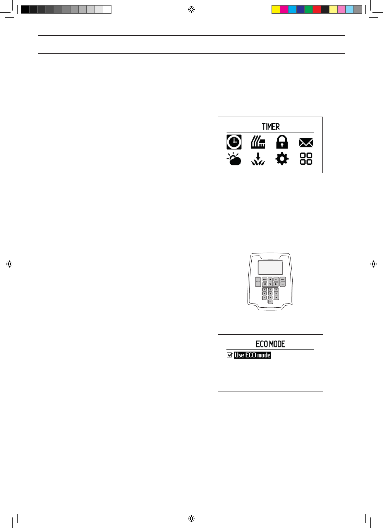
Maaier doet het niet. Er staat lus systeem uit (ecomodus) Gesteld op 10-3-2022 om 15:37
Reageer op deze vraag Misbruik melden -
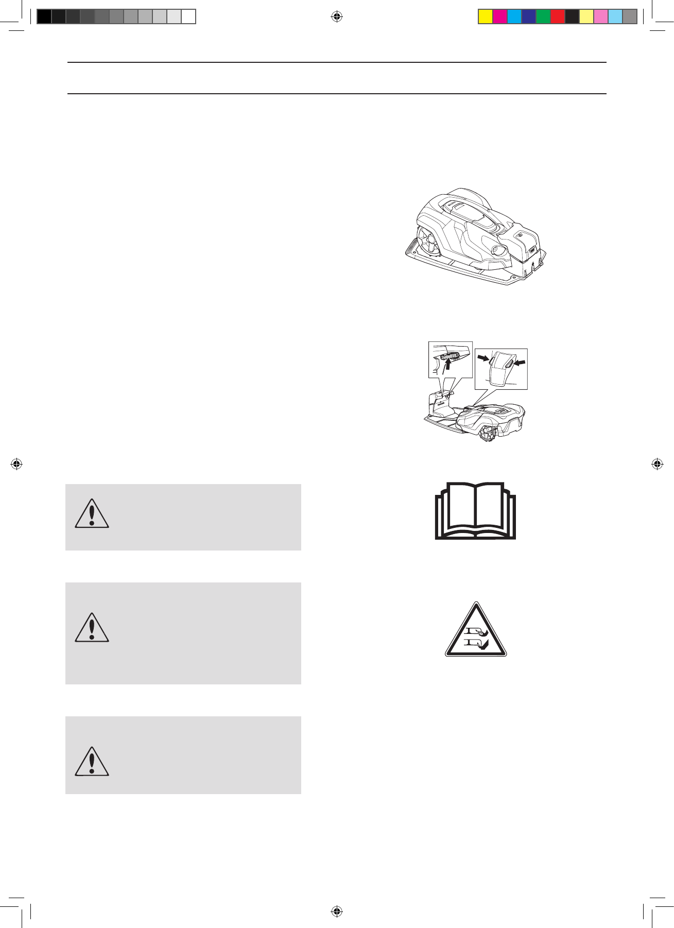
Mijn 430X verliest zijn voorwiel. Hoe terug plaatsen Gesteld op 24-10-2021 om 14:54
Reageer op deze vraag Misbruik melden-
Bovenkant van de automower verwijderen door alle schroeven los te draaien. Waarschijnlijk is het borgveertje van het voorwiel door roest afgebroken. Nieuw borgveertje plaatsen. Zijn na te bestellen of bij een bouwmarkt te kopen. Geantwoord op 24-10-2021 om 15:00
Waardeer dit antwoord (6) Misbruik melden
-
-
De klok van de 430X geeft niet de juiste tijd aan. Hoe kan ik de klok verzetten? Gesteld op 4-9-2021 om 10:22
Reageer op deze vraag Misbruik melden -
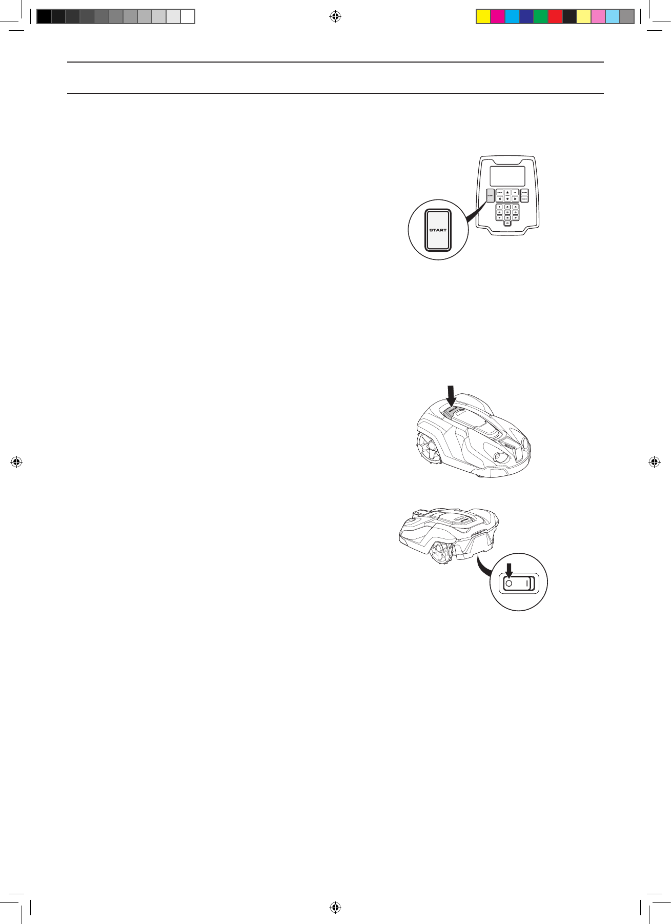
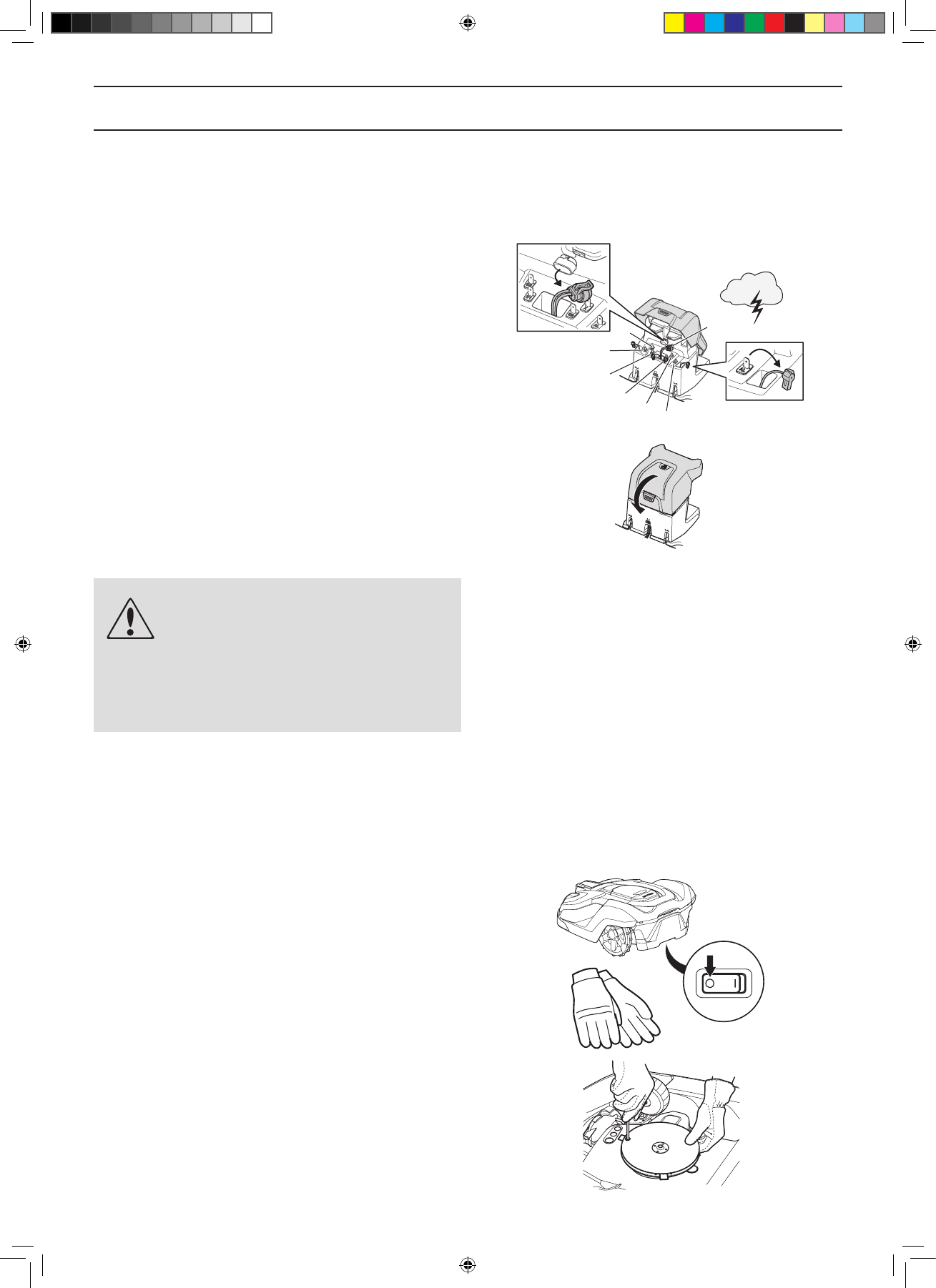
de motormaaier op zijn kop gehad en krijg deze niet meer aan de gang, wat nu?
Reageer op deze vraag Misbruik melden
Gesteld op 24-3-2021 om 14:20-
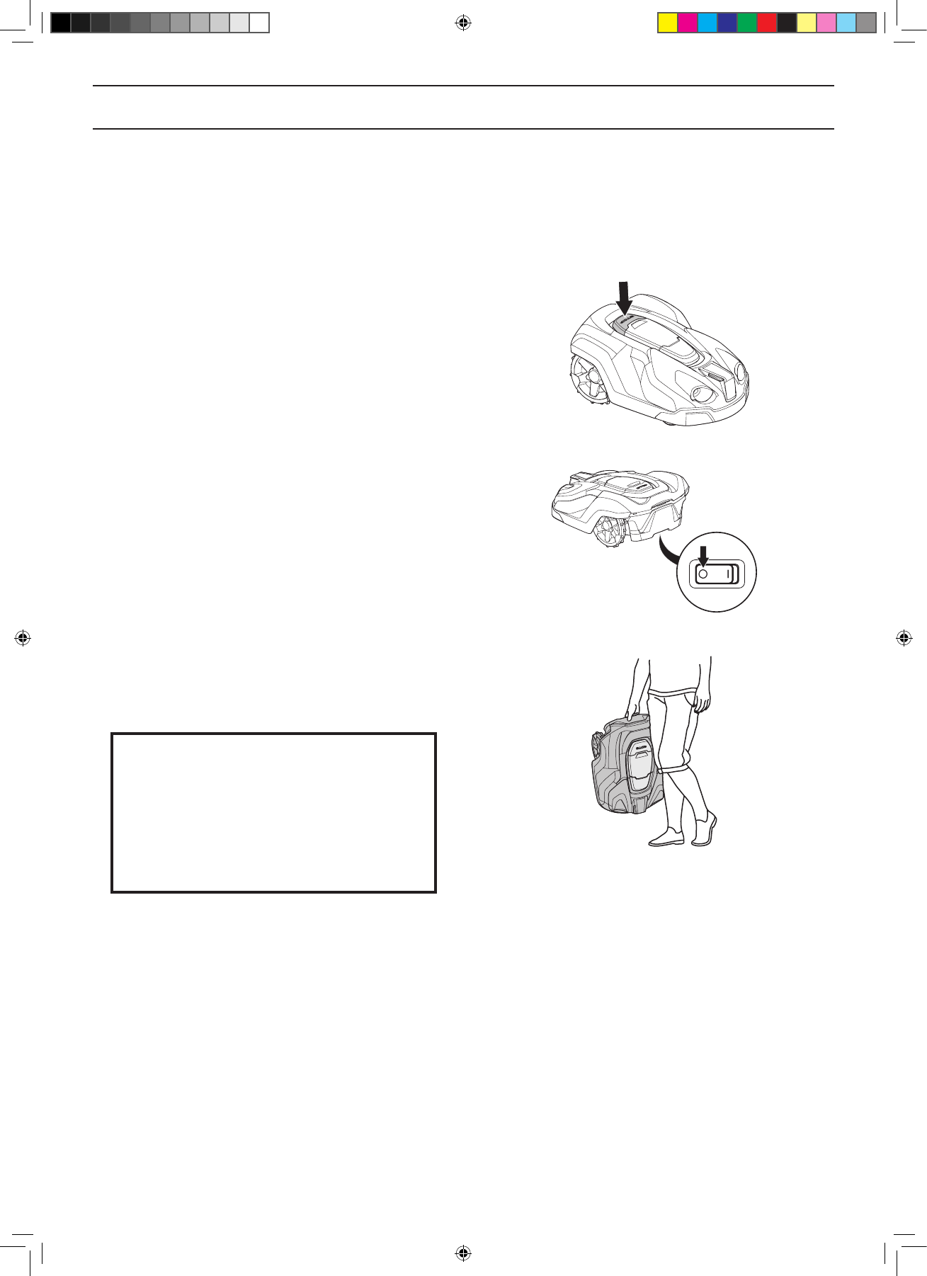
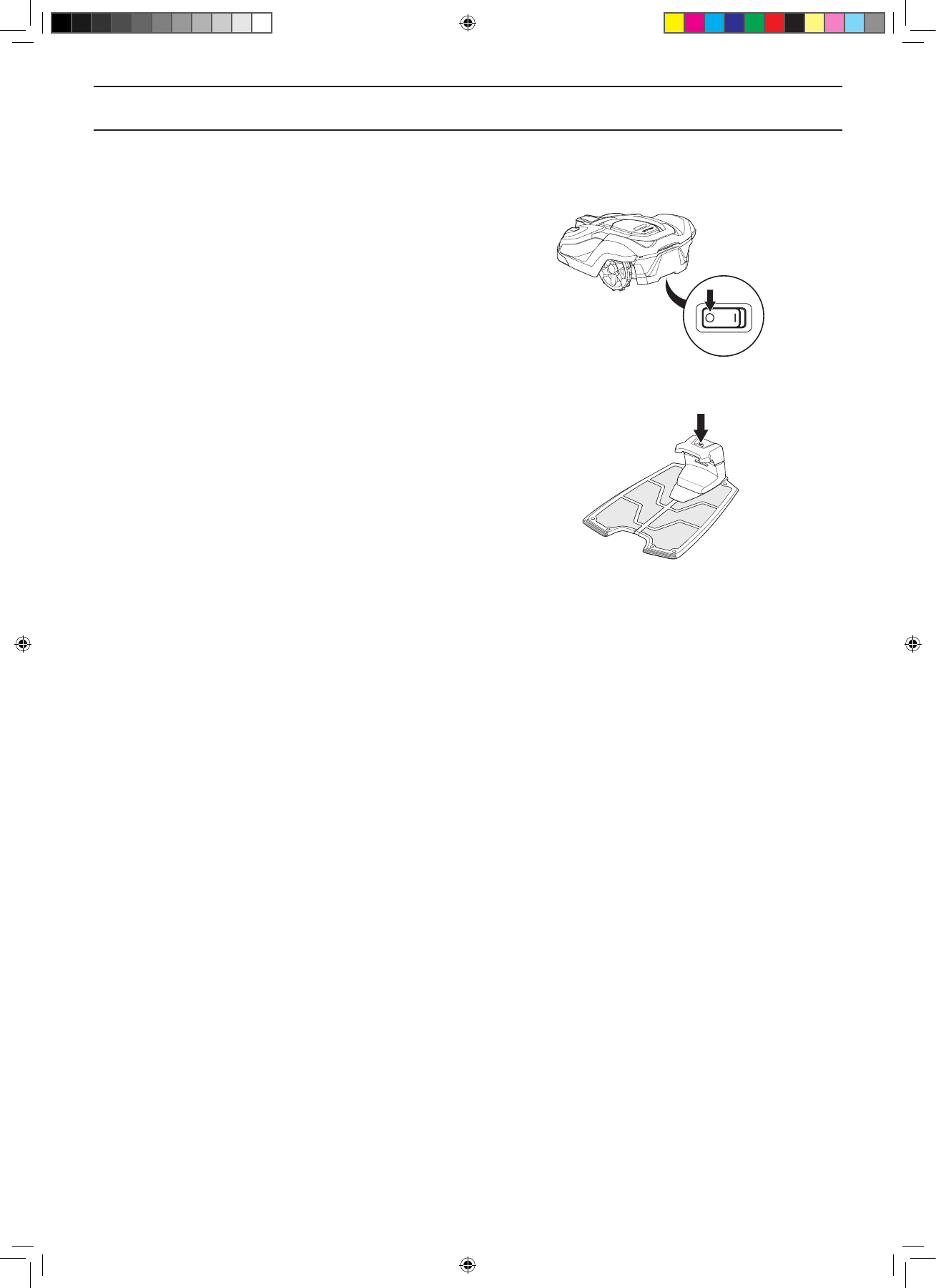
Eerste uitschakelen met de knop onderaan de achterzijde van de maaier, daarna weer overeind zetten en op het laadstation plaatsen en met die knop weer aanzetten. Vervolgens weer op de normale wijze via de klep inschakelen en activeren. Geantwoord op 24-3-2021 om 16:00
Waardeer dit antwoord Misbruik melden
-
-
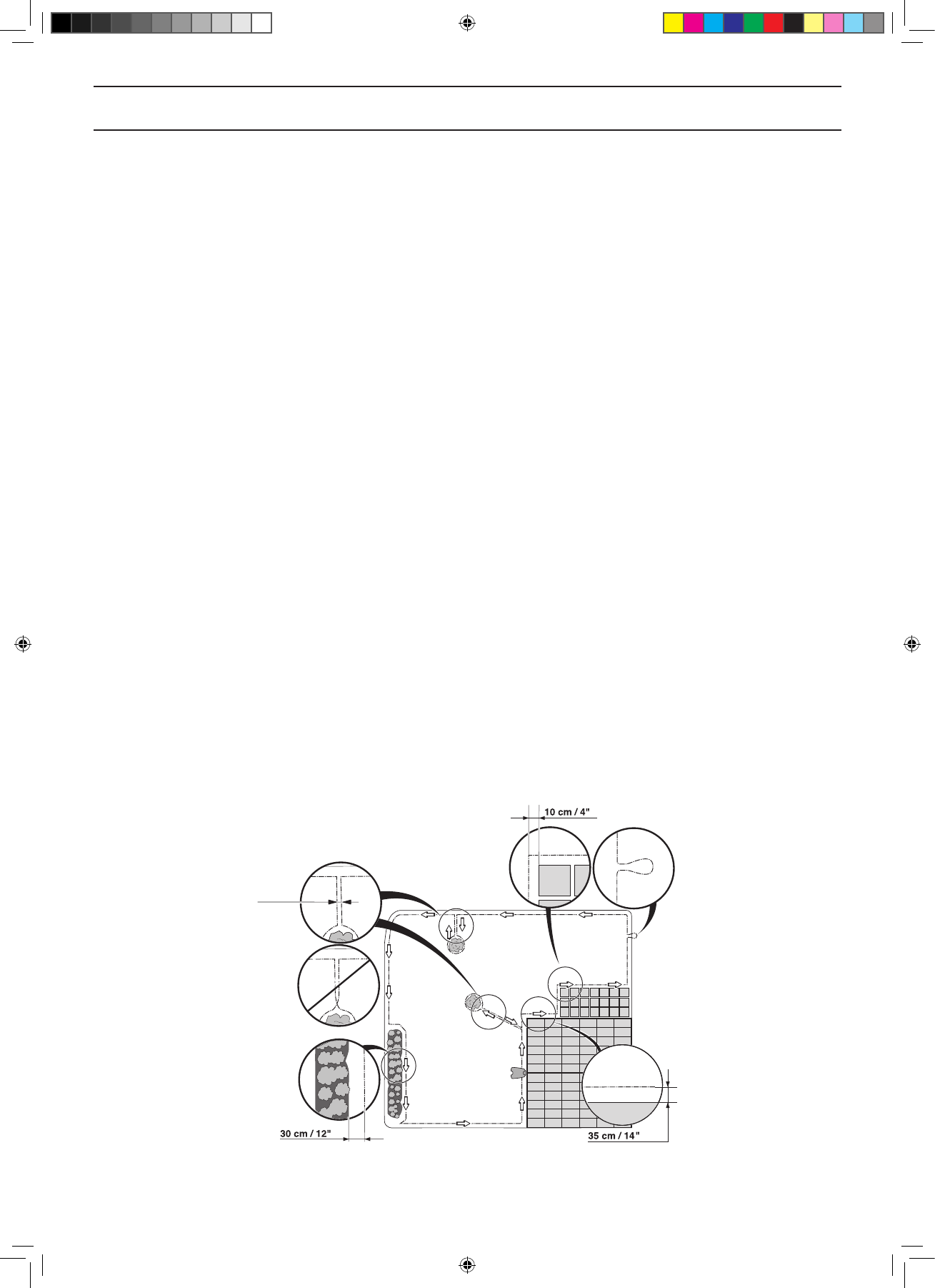
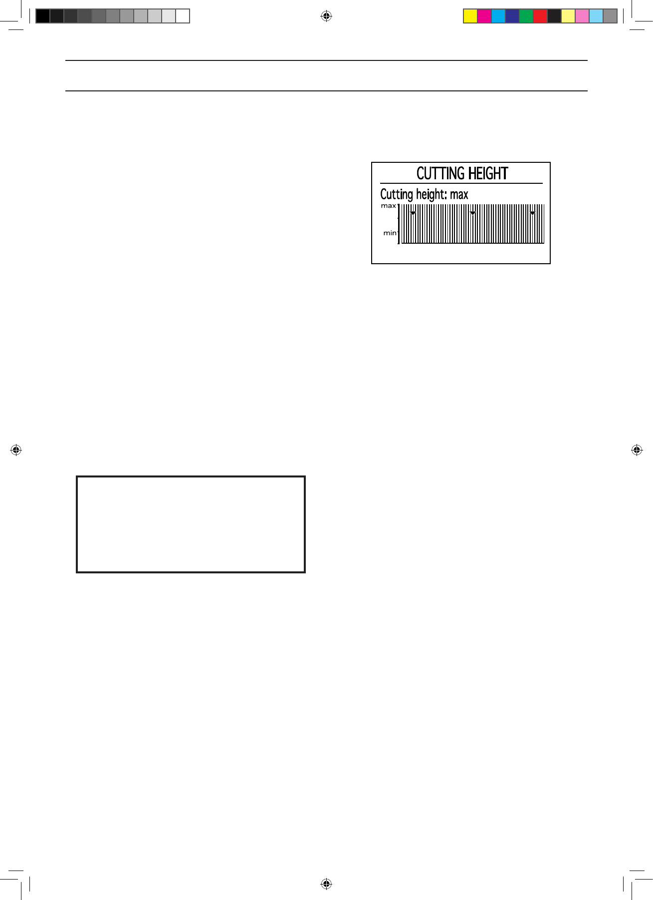
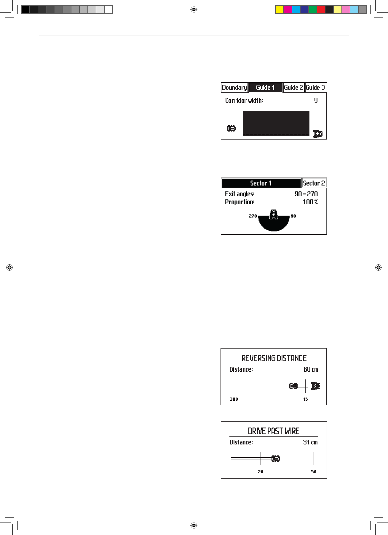
automower 430X ingesteld om 40 cm over begrenzingsdraad te rijden, maar laat bij de rand van de tegels veel gras staan. Kan hij niet met 1 wiel over de tegels de hele rand maaien? Een ander merk kan het wel. Gesteld op 22-8-2020 om 22:36
Reageer op deze vraag Misbruik melden-
De draad moet dan anders gelegd
Waardeer dit antwoord Misbruik melden
Is bij ons ook gebeurd Geantwoord op 27-3-2021 om 09:29
-
-
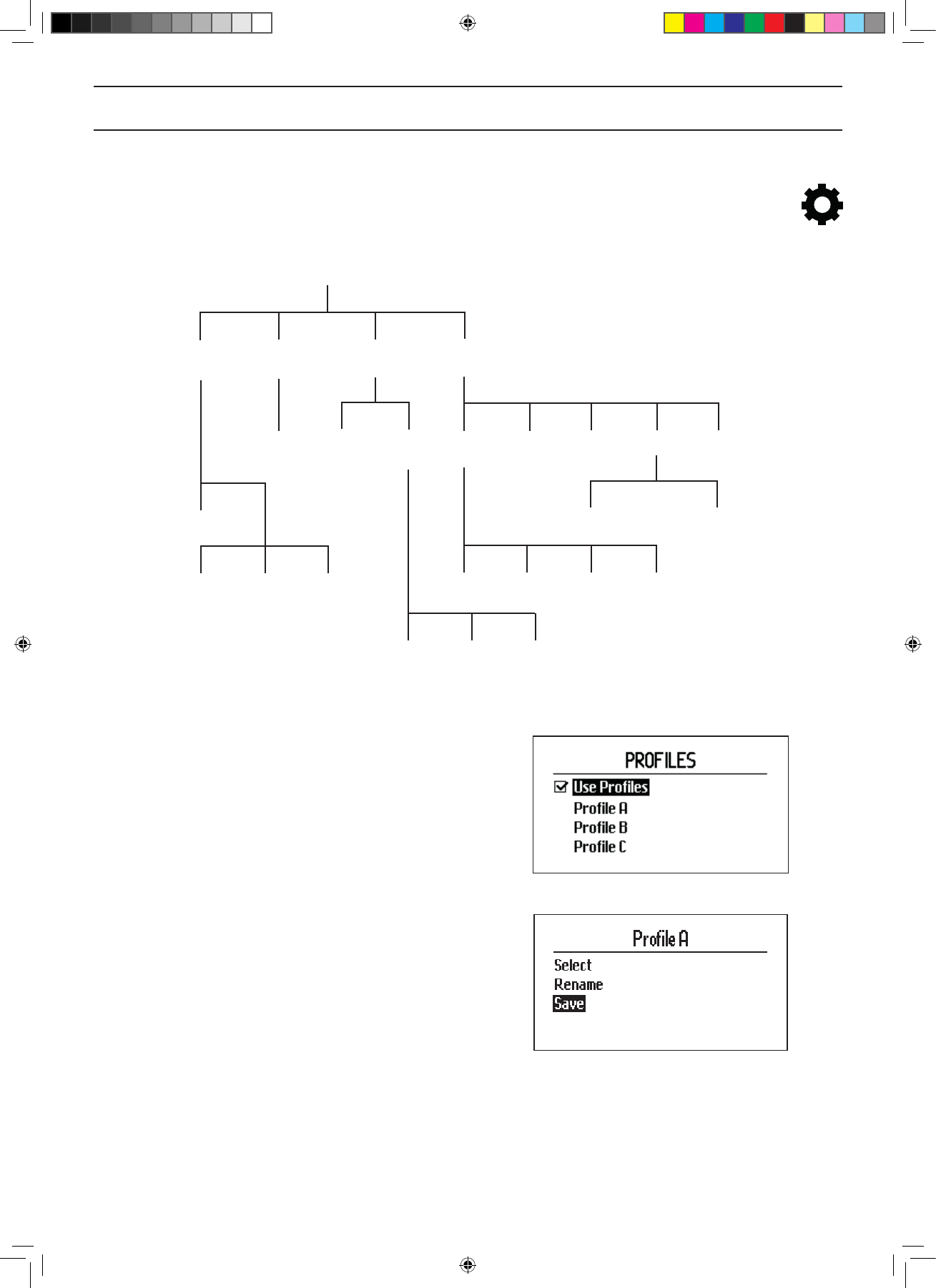
hoe kan ik bestaande profiel opslaan op mijn huidige automower 430x ?
Reageer op deze vraag Misbruik melden
Gesteld op 9-5-2020 om 12:59 -
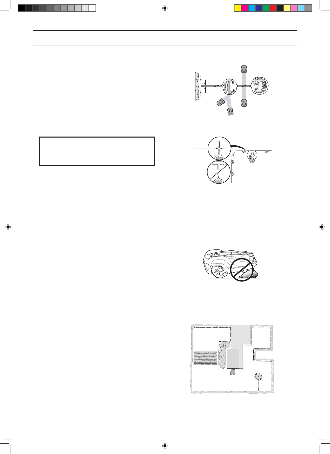
ik heb een stuk verhard terein waar mijn automower over moet om een ander stuk te maaien maar ook daar maait hij telkens alsof het gras is !
Reageer op deze vraag Misbruik melden
Hoe kan ik dit oplossen, ik dacht eraan om op die plaats mijn begeleidingsdraden samen te leggen nu liggen deze ongev 60cm uit elkaar ? of is er een betere oplossing?
Freddy Brodeoux
email: freddy.brodeoux@gmail.com Gesteld op 25-4-2020 om 09:49 -
Robotdiet het niet en in display staat opgetild
Reageer op deze vraag Misbruik melden
Gesteld op 9-3-2020 om 17:29 -
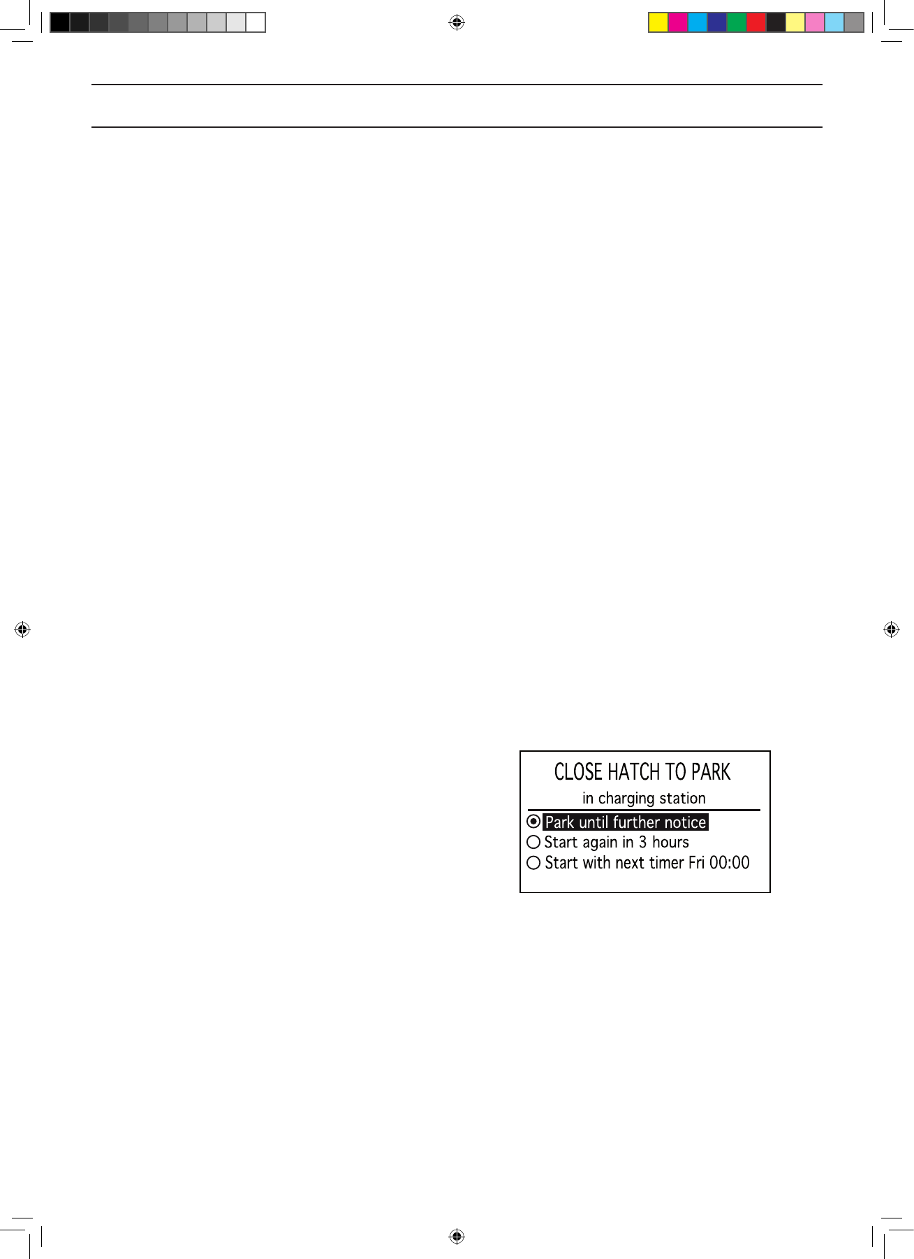
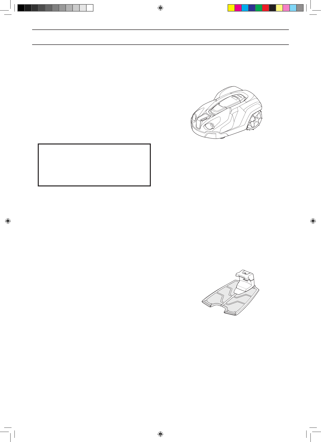
hoe moet de robot worden opgeslagen in de winter horizontaal of moet hij verticaal worden gestald? Gesteld op 2-11-2019 om 09:29
Reageer op deze vraag Misbruik melden-
Maakt geen verschil. Ik sla de maaier altijd 's winters op in horizontale stand in een vorstvrije ruimte. Geantwoord op 2-11-2019 om 14:19
Waardeer dit antwoord Misbruik melden
-
-
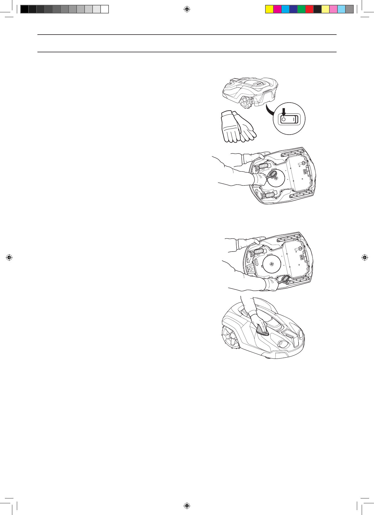
Hoe moet de mover aan de onderkant schoon ge maakt worden ,de mover staat nu in het laadstation Gesteld op 3-7-2017 om 21:30
Reageer op deze vraag Misbruik melden-
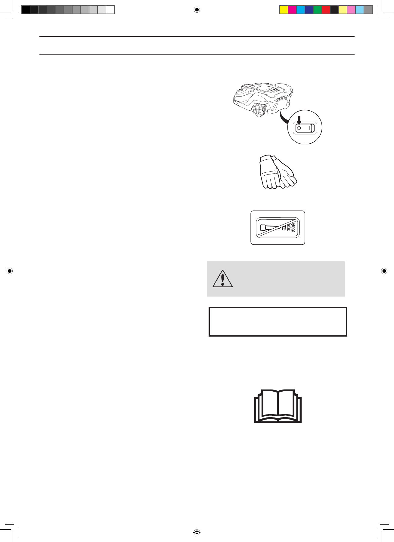
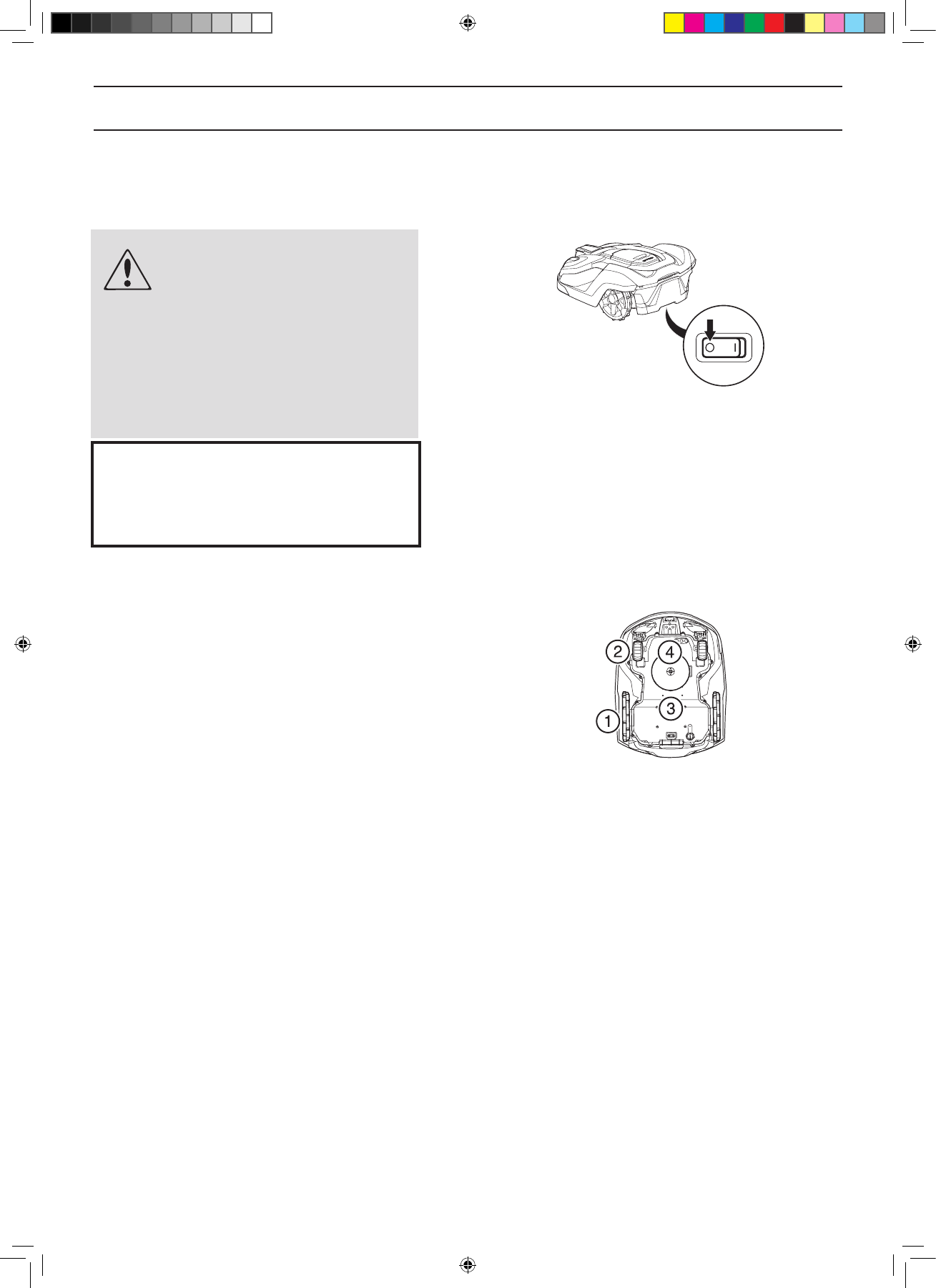
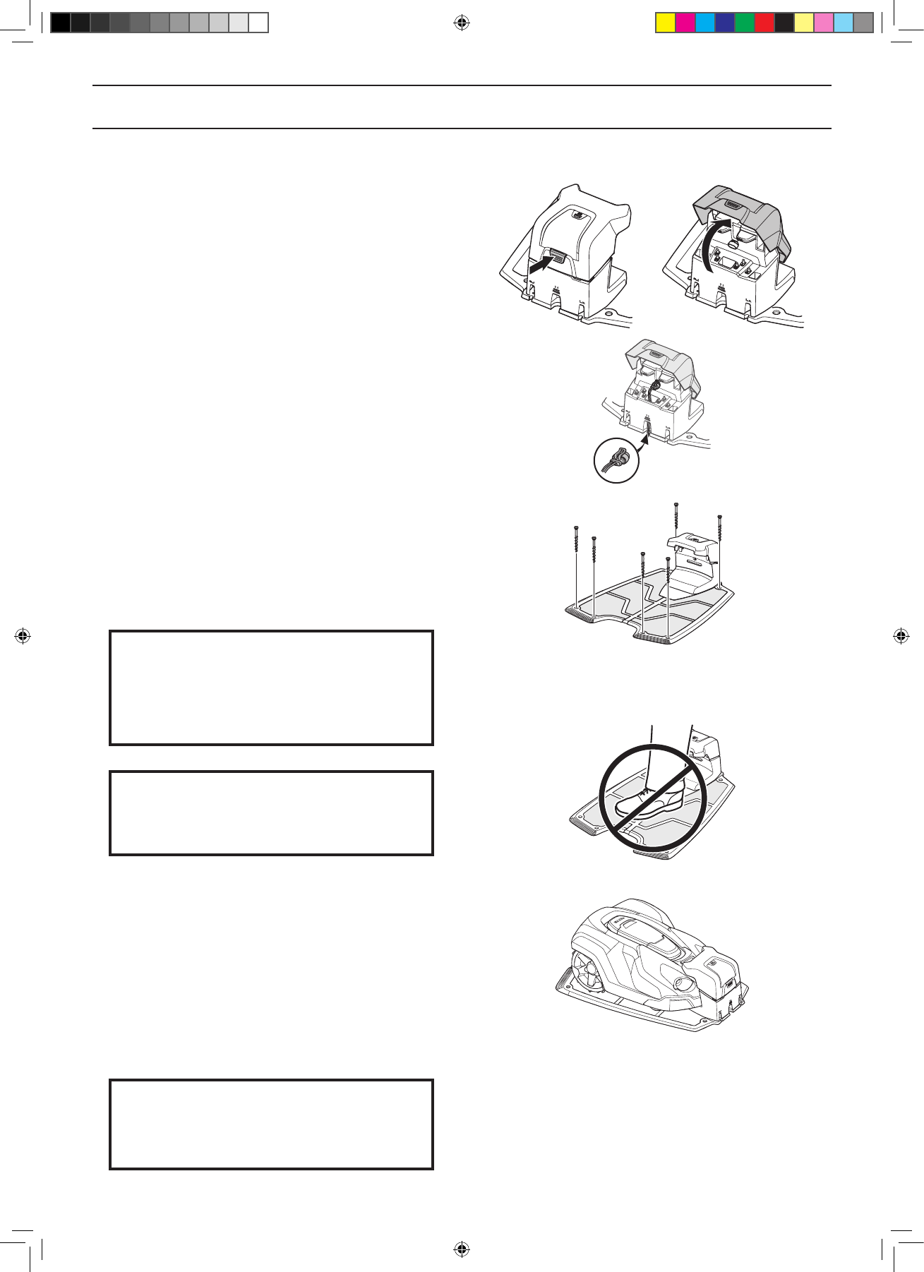
1. Druk de stopknop in. 2. Voer de pincode in. 3. Zet de schakelaar op 0. 4. Draai de automower op zijn zijde en maak met een zachte borstel schoon.. 5. Zet de aotumower op zijn wielen. 6. Zet de schakelaar op 1. 7 Voer de pincode in. 8. Druk op start. 9. Sluit de klep. Geantwoord op 4-7-2017 om 17:06
Waardeer dit antwoord Misbruik melden
-
