This user manual will inform you, on the one hand, about the technology, installation, commis-
sioning and functioning of HomematicIP. On the other hand, you will find numerous answers
to questions for everyone who is in home automation and HomematicIP in general.
You will furthermore be provided with basic information on the topic of smart home and
radio technology, giving you valuable tips for planning and the optimum operation of the
HomematicIP System.
Introduction
7
2 INTRODUCTION
A smart home oers automation of recurring day-to-day operations and tasks in houses or
flats: While using an appropriate system, dierent (technical) devices and functionalities can be
connected within one household in order to control them as comfortably as possible and for
the automation of recurring tasks.
In the following pages, you will find detailed information on HomematicIP in general, for start-up
and for the control of your system.
2.1 eQ-3 - a Company
On the smart home market, eQ-3 counts among the innovation and technology leaders, and it
is considered a pioneer especially in the home control area. In 2021, eQ-3was thus elected -
for the fifth time running - the European market leader1by Berg Insight, the renowned Swedish
market research institute. With its own brands and OEM products, eQ-3 has a 40 % share of the
installed base of all whole-home systems in Europe. Moreover, the manufacturer has more than
200 product types and thus the broadest portfolio in the smart home sector industry-wide. More
than 2 million households were equipped to date with over 36 million radio solutions.
2.2 Overview of HomematicIP
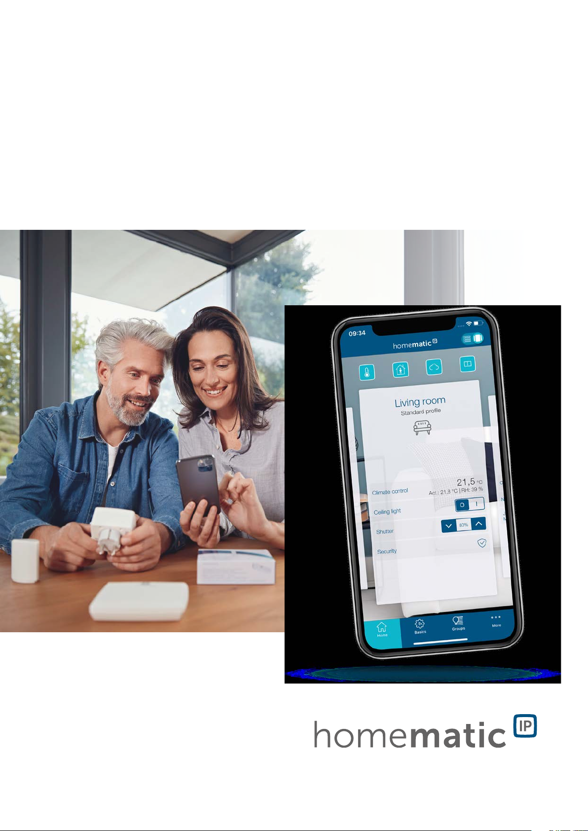
HomematicIP helps turn your regular home quickly and easily into a smart home. The system
will win you over, in particular, with its simplicity and reliability.
The steadily increasing product range comprises the areas of indoor climate, light and shading,
safety and alarm as well as weather, environment and access. The practical starter sets oer
the easiest way to get started. They can be flexibly expanded at any time. The system is thus
suitable for any application: whether new construction or renovation, your own house or a rental
accommodation.
Installation of the system is fast and simple, without prior knowledge, via the free HomematicIP
smartphone app and a HomematicIP Access Point. The free of charge Cloud service enables
control of the system via one or several smartphones – even while en route. Other operating
options are directly available on HomematicIP equipment, via practical remote controls or by
voice command via Amazon Alexa/Google Assistant.
The easiest way into the smart home – set up swiftly and intuitively
HomematicIP oers various possibilities for setting up a smart home. The Cloud solution of
HomematicIP provides the ideal solution for everybody.
The easiest and most economical way of starting into the smart home is the HomematicIP
Access Point. As a gateway, it provides the connection between the HomematicIP devices and
the HomematicIP Cloud in which the setup and configuration of the system is anonymously
stored — required is only recording the IP address for technical reasons.The free HomematicIP
smartphone app is available as the operating element to download for Android operating systems
and iOS. The combination of cloud and app enables a particularly swift, simple and secure setup
and operation of the smart home.
1 Smart Homes and Home Automation Study (02/2021) Berg Insight concerning "Whole Home" systems
Introduction
8
Single devices are configured by the free HomematicIP Cloud Service, which is run exclu-
sively on servers located in Germany and therefore complies with European and German data
protection guidelines. Furthermore, all communication between the Access Point, cloud and
app is encrypted. Neither during nor after installation of the app, you will need to provide private
data such as name, email address or mobile phone number.
All products communicate via the robust and reliable 868 MHz HomematicIP Wireless Protocol.
There are no interferences caused by WLAN, Bluetooth or other radio standards operating within
the 2.4GHz frequency band.
Anonymity for maximum data protection
Your home is the most crucial private area. This is where you want to feel not only at ease and
secure but safe as well. Accordingly, the decision for a smart home should certainly not come
at the cost of any compromises in the areas of data protection and security.
HomematicIP can also be relied upon at this point. Because your privacy is already protected in a
first step: No personal data are queried or recorded for the system setup – aside from the techni-
cally necessary IP address. Moreover, all data saved in the HomematicIP Cloud are provided on
servers in Germany and are thus subject to the German and European data protection guidelines.
HomematicIP is the only smart home system whose protocol, IT and data security has been
certified by VDE.
In addition to the security of your data, the transmission security also ranks first. The
communication of HomematicIP is secure and cannot be manipulated. Any reading or changing
of data or other kinds of attack are impossible. Approved procedures are used for it which are
also applied in online banking.
Oine operation – direct communication of devices without the internet
“A cloud-based smart home does not work without the internet” – that’s just one of the
innumerable prejudices concerning smart home systems, and for some providers, this might
even be true. HomematicIP proves just the opposite: Owing to the use of the IPv6 protocol,
every HomematicIP device has its own IPv6 address for communication within the system. Thus,
storage of information and device status is enabled directly in the devices themselves – without
use of the cloud. Such direct communication among themselves results in a high fail safety and
very low latencies, thus remarkably fast execution of commands.
While an internet connection is required for the setup and control, the basic functions are
working oine anytime. This comprises the direct operation on the devices (for example, to
switch on the light), the execution of heating, time and shading schedules, as well as local alarms
in the security area.
HomematicIP received several awards already
HomematicIP is convincing in every respect and also scores all around the important security
standards. This is confirmed by independent institutes: In March 2020, the AV TEST Institute
distinguishes HomematicIP already for the third time running as a data protection-friendly,
smart home solution.
Moreover, HomematicIP is the first smart home system whose protocol, IT and data security
has been certified by VDE. In this respect, the tests concern not only the total system but also, in
detail, the Access Point, the backend version, the respectively valid iOS and Android app versions
as well as the wireless-based protocol.
In examinations by the German product testing foundation ‘Stiftung Warentest’, HomematicIP
products also achieved time and again top marks in the tests. These products include, among
others, various radiator thermostats.
Introduction
9
Yet more possibilities thanks to open interfaces
HomematicIP covers many user wishes with the product portfolio. Moreover, the system can
be operated with Amazon Alexa and Google Assistant which not only enables comfortable
voice control, but also the preparation of individual, multi-vendor scenarios. The open system
interfaces are additionally used for tying in other IoT platforms, such as Home Connect + or
mediola. That’s how the smart home will become even more individualized and more extensive.
* Smart Homes and Home Automation study (02/2021). Berg Insight on whole-home systems.
Introduction
10
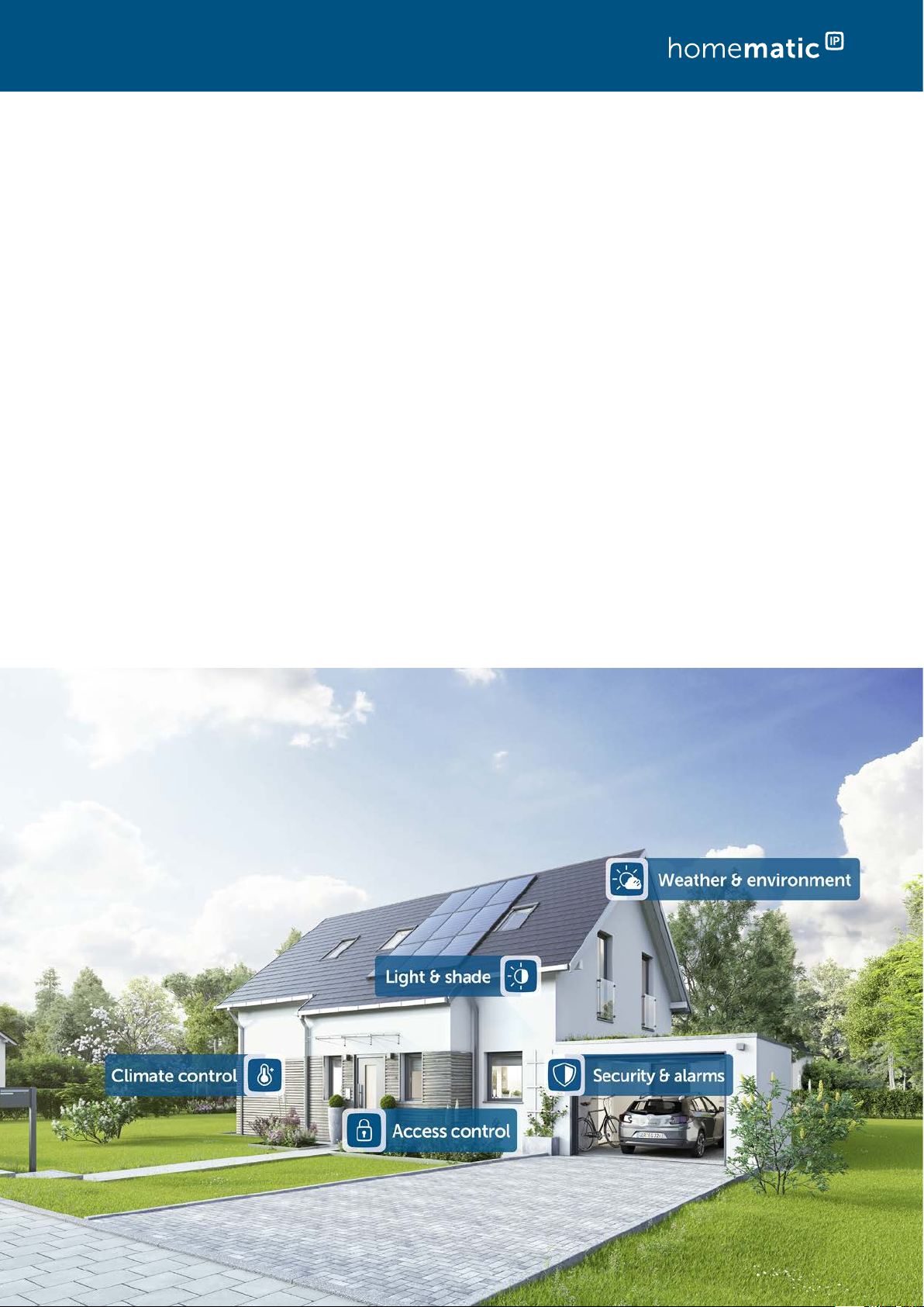
2.3 Application areas
Room climate
HomematicIP oers demand-based control of radiators room-by-room in the entire house,
enabling increased living comfort and energy savings of up to 30 %. The HomematicIP Window
/ Door Contact detects open windows and doors and automatically turns down the heating
during ventilation. In addition, ecient floor heating control that oers operation via app can
be realised with HomematicIP. The system detects the required heating demand for individual
rooms and – unlike conventional heating circuit control systems – intelligently circulates the hot
water into the dierent heating zones. This provides load balancing and ecient energy distri-
bution thanks to the continuous flow of heating water. The room temperature can be regulated
via radiator thermostats, an installed wall thermostat or simply via app. Also, individual heating
schedules can be created with HomematicIP. Afterwards, your heating is controlled automati-
cally and makes everyday life easier. However, you can still react flexibly to changed conditions
and adjust the desired temperature according to your needs.
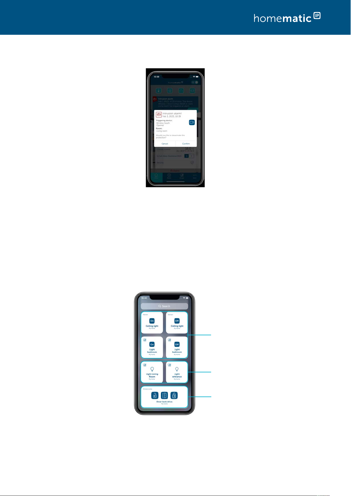
Security and alarms
No movement goes unnoticed with HomematicIP security components. Our security and alarm
products increase the protection against break-ins and the sense of security inside one’s own
four walls.
In alarm mode, users are informed whenever windows and doors are opened. Motion detectors
oer reliable monitoring for inside and outside areas while sirens trigger an alarm in case of
break-ins.
Just a quick glance at the app is all it takes to see that everything is as it should be at home. So
you no longer need to worry about windows and doors being left open. And that even if you’re
thousands of miles away.
The alarm mode can be easily activated via app or HomematicIP Key Ring Remote Control. If
the presence mode is activated, the system triggers an alarm as soon as windows or doors are
opened unauthorised, for example. If the absence mode is activated, sensors for indoor areas
like the motion detectors are additionally included. In case of an alarm, an audio signal can be
triggered not only via the HomematicIP Siren; a push notification can also be sent to all regis-
tered smartphones. The event protocol provides an overview of all activities in your home at
any time.
For every application the
appropriate solution –
SIMPLY SMART!
Introduction
11
Access
With HomematicIP, you can easily make your front door smart and turn your smartphone into
a digital key. The door can thus be opened at any time via the free smartphone app or via the
practical remote control.
Thanks to configurable access authorizations, access to the smart home can be individually
managed – regardless of the day of the week or the point in time. The front door can only be
opened when you want it to. Thus, for example, cleaning personnel or nursing care services can
access the house only at specific times and via Key Ring Remote Control.
Is the front door really locked? Thanks to scheduled locking and unlocking, this question is moot.
You can schedule the front door to lock automatically at any desired time (e.g. over night) This
not only increases the security of your smart home, but it also saves you from having to go check
the front door. For those who want to play it safe, you can also schedule the front door – after
each unlocking action – to automatically relock the door immediately again.
Light and shade
Comfortable switching and dimming of lights creates a sense of well-being at your home. Thus,
a comfortable atmosphere for TV evenings is created via the app as the ceiling light is dimmed
to a desired brightness level while the floor lamp is switched on. Also, the sense of security is
increased with an illuminated driveway or house façade in the evening.
Shutters and blinds darken rooms; they create a sense of privacy and increase security. With our
shutter and blind actuators, the window coverings can be set up with just a few turns of the hand
via the HomematicIP App. Afterwards, they can be raised or lowered automatically.
The actuators are conveniently controlled via individual week-long profiles that also factor in
sunrise and sunset. Furthermore, active shutters and blinds make the home look inhabited even if
you are not at home. In addition to the anti-burglary eect of shutters, our solution thus actively
increases security. Another advantage: In case of increased room temperatures due to strong
sunlight, shutters or blinds are automatically lowered to prevent the rooms from heating up.
The HomematicIP Blind Actuators also allow the exact adjustment of the slats position of
exterior and interior blinds. If necessary, awnings can also be integrated into the smart home
using our products. The automatic storm protection avoids damage to shutters, interior blinds,
or awnings during unfavourable weather conditions and thus raises or lowers the window
coverings.
Weather & the environment
With the weather sensors, the HomematicIP smart home system is automatically adjusted to
the particular weather condition. In connection with other HomematicIP devices, the sensors
can automatically trigger commands for moving awnings, interior blinds or shutters up or down
in case of certain weather conditions, providing active protection of your home. In this respect,
users have almost unlimited possibilities for creating individual rules. Thus, it is possible for
example, in case of strong sunlight and inactive security mode, that the awning is automati-
cally extended to 80 % or that, with a previously defined rainfall volume, the drainage pump is
activated for a certain period of time.
Introduction
12
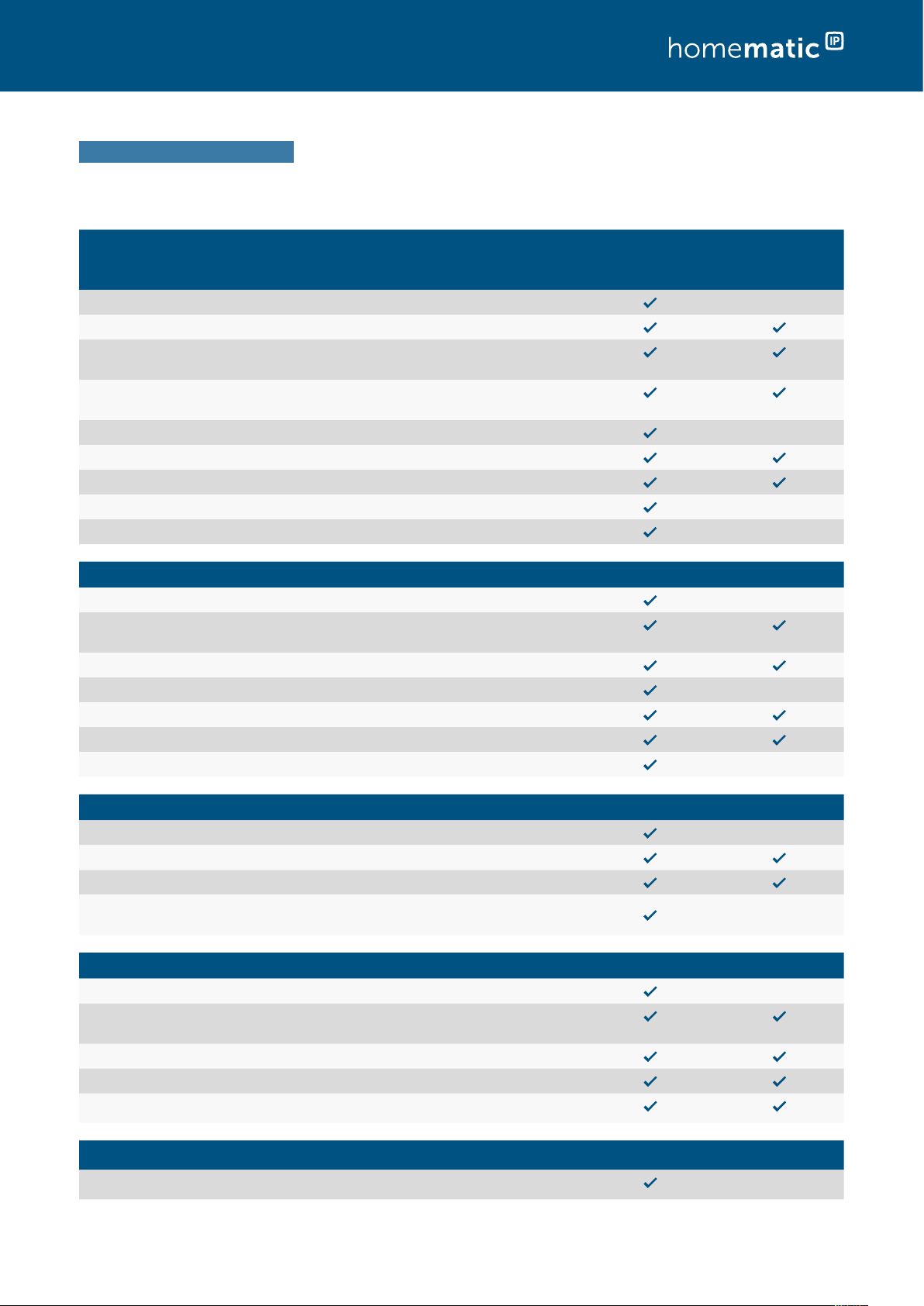
2.4 Summary – Discover why HomematicIP is the first choice
Simplicity
The entire solution can be intuitively set up and comfortably controlled via smart-
phone app. Single devices are configured by the HomematicIP cloud service. As the
devices communicate via radio, they can be retrofitted into houses really easily and
also expanded at any time.
Interference immunity
HomematicIP is based on the 868MHz radio band. There is no interference
whatsoever from WLAN, Bluetooth, video streaming or other users of 2.4 GHz.
Superior range
Reliable communication between HomematicIP devices works even over a distance of
a few 100 meters. Even for remote places, you need not worry about the functionality
of your chosen smart home solution.
Uncompromising security
Already during installation of the system the communication of HomematicIP is secure
and cannot be manipulated. During operation, all radio packages are encrypted and
authenticated. Reading, changing or repeating data or other kind of attacks are impos-
sible. Similar to online banking, the universally accepted AES-128 and CCM standards are
used. The HomematicIP Cloud operates exclusively on German servers. HomematicIP
is the first smart home system for which VDE certified not only the IT and data security
from smartphones via the cloud all the way to a gateway inside the house, but for which
certification of security was also realised for the wireless protocol.
Battery operation
HomematicIP focusses, among others, on battery operated devices in order to enable
smart home installations also in existing buildings. The products can be easily screwed
on to radiators or stuck to walls. Thanks to the low energy consumption of the devices,
batteries usually only need to be replaced every two years, or even less frequently.
Reliability
The radio communication between HomematicIP devices is always going on bidirec-
tionally. The receiver confirms every radio command that is sent to him and reports
to the sender that a command was recognised and executed. Thanks to IPv6 , the
system has a secure future and is optimally prepared for the internet of things. Bidirec-
tional communication oers increased reliability for every system. On the other hand,
and based on the type of feedback, you are informed about the current status of the
devices involved at any time (e.g. window status or switching state).
Privacy policy
For setting up the system, no personal data has to be provided, except the IP address.
The HomematicIP Cloud is only operated on servers located in Germany. The
operation does therefore comply with European and German privacy policies.
Experience
HomematicIP is the smart home solution and technology by eQ-3 AG. Based on
long-term experience in developing wireless smart home products, eQ-3 has estab-
lished itself as the European market leader*2 in home control.
2 * according to Berg-Insight (02/2021). Installed base of whole-home devices.
Components of the HomematicIP system
13
3 COMPONENTS OF THE HOMEMATICIP SYSTEM
3.1 HomematicIP devices
The devices of the HomematicIP system are characterised by an attractive, uniform product
design. Largely determinative were the main aspects of ergonomics and usability. This applies
to the individual devices whose design and functional elements were reduced to the essentials,
which significantly simplifies the operation.
Detailed information about the single HomematicIP devices can be found in the product
datasheets of the HomematicIP devices, available for download at the website
www.homematic-ip.com.
3.2 HomematicIP Cloud
The HomematicIP Cloud enables communication between the app and the Access Point as
well as saving and managing of system relevant data. This encompasses e.g. information about
which devices have been added or connected, as well as details about the configuration.
All communication between the Access Point, cloud and app is encrypted. The system can be
put safely into operation without entering any private data – exclusively by scanning the QR
code and pressing the button at the Access Point; solely the IP address is necessary for technical
reasons.
3.3 HomematicIP smartphone app
Via the HomematicIP smartphone app you can set-up your smart home solution. The app oers
step-by-step guidance through the entire installation process. All necessary links between the
devices are established automatically.
After set-up, the app takes over the function of a central control unit, enabling you to control
and configure your entire HomematicIP system. In addition, the app informs you about the
current status of your devices at all times.
No matter where you are:
With the free smartphone app, you have
everything in sight. Control your smart home
at any time from any place.
Simply comfortable.
Components of the HomematicIP system
14
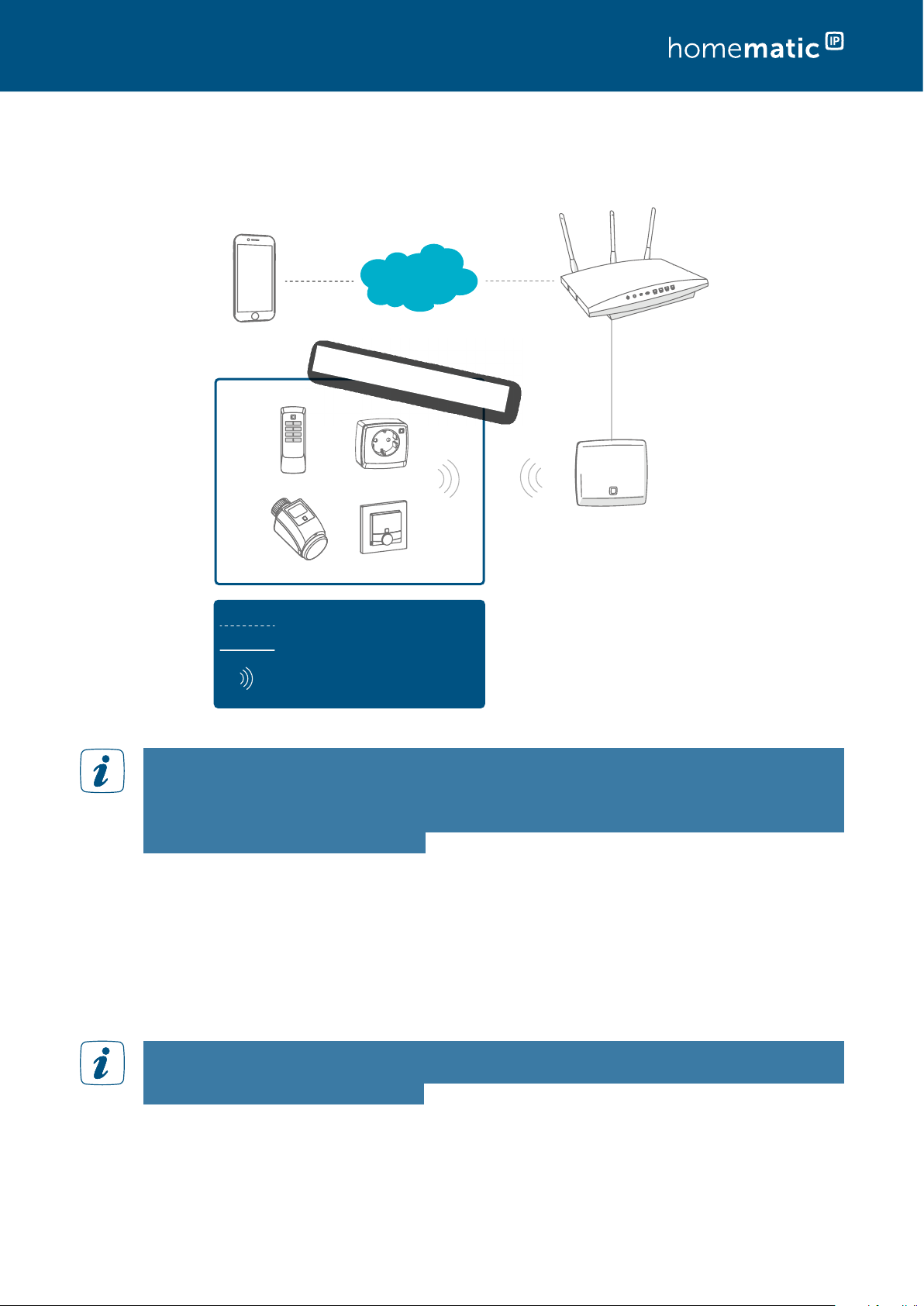
3.4 Operating principle of HomematicIP
Homematic IP
Access Point (HmIP-HAP)
Homematic IP devices
LAN
Data connection (mobile data)
Wireless
Cloud-Server
Homematic IP
App
Router
All data stored in the HomematicIP Cloud are completely anonymous. That means they
do not permit any conclusions about the user’s identity and the individual user behaviour
– it is only required to record the IP address for technical reasons. The identification of
a HomematicIP user is – even theoretically – only possible as part of a criminal prose-
cution and based on a court order.
The HomematicIP smartphone app – together with the cloud and the Access Point – enables
the setup, programming and controlling of your smart home system. A scan function in the
app makes integration of individual HomematicIP components into the system very easy by
scanning the device QR code. To make sure that the system continues to run even in case of
an internet failure, all necessary links among the devices are determined by the HomematicIP
Cloud Service and created automatically. Thanks to direct links among the devices, it is ensured
that the operation still continues even during an internet failure.
All communication between the Access Point, cloud and app is encrypted. Neither during
nor after installation of the app, you will need to provide private data such as name, email
address or mobile phone number.
Home control by wireless technology
15
4 HOME CONTROL BY WIRELESS TECHNOLOGY
4.1 Wireless range
eQ-3 benefits from more than 40 years of experience in the field of wireless technology for
smart home applications. HomematicIP is based on particularly eective and robust wireless
technology like Homematic and has proven its market success with millions of devices.
The wireless range of HomematicIP exceeds the standard requirements of a typical installation.
Depending on the device type, a wireless range between 150 and 400 meters in the open air
can be reached. Experience shows that, in less than 1 % of the installations, repeaters are used
to extend the wireless range.
Radio waves behave in a similar way as sound waves. They can penetrate walls and spread out in
all directions. Similar to the volume of sound, the energy of radio waves decreases with distance.
Thus, the range of radio waves is limited.
In practice, there are factors that can influence the radio signal in a positive and negative way,
compared to the range in the open air.
Information on the extension of the wireless range is found in section (see section “4.2
Advanced routing” on page 16).
Information on the extension of the wireless range is found in(see section “4.2 Advanced routing”
on page 16).
The following table gives an overview of the damping eects of individual building materials:
Building materialDamping
Pumice stone/autoclaved aerated concrete
Gypsum and gypsum plasterboard
Uncoated glass
Metallised glass
Wood
Metal grille (e.g. in plaster)
Press boards
Stone slabs
Brick
Home control by wireless technology
16
4.2 Advanced routing
Due to the extension of the HomematicIP Protocol with advanced routing, the HomematicIP
system will become even more flexible and provides the following advantages:
Extension of the wireless range via additional Access Points to practically any arbitrarily
sized buildings or in more remote living areas, such as e.g. the garden house.
Fail safety for direct links between HomematicIP devices by tying in an additional
Access Point.
Homematic IP
Access Point (HmIP-HAP)
Advanced Routing
Homematic IP devices
LAN
Data connection (mobile data)
Wireless
Cloud-Server
Homematic IP
App
Router
Homematic IP
Access Point (HmIP-HAP)
4.2.1 Range extension
Generally, HomematicIP wireless components communicate – owing to their open field
range of about 150 to 400 meters – trouble-free even over considerable distances within
buildings. However, it cannot be excluded that the range is impaired in case of larger buildings,
unfavourable structural conditions or non-ideal placement of components.
In order to optimise the wireless range in these cases, HomematicIP principally oers two
possibilities:
• Range extension by an additional Access Point (HmIP-HAP)
• Range extension by Pluggable Switches or Pluggable Switches and Meter, respectively
4.2.1.1 Range extension by an additional Access Point
Expansion of the HomematicIP Protocol renders it possible to tie in an additional Access Point
into a HomematicIP installation. Thanks to advanced routing, the wireless range can be signifi-
cantly increased, if necessary; for example, if the optimum wireless covering over several floors
or in larger buildings is concerned.
In a comparison regarding range extension with HomematicIP Pluggable Switches or, respec-
tively, Pluggable Switches and Meter, the use of an additional HomematicIP Access Point is to be
preferred. This provides the advantage that the duty cycle3 of an installation – due to increased
radio communications – is not reached as fast if an additional Access Point is used than in case
3 The duty cycle is a legally regulated limit of the transmission time of devices in the 868 MHz range. In the 868 MHz frequency range which we use, the
maximum transmission time of any device is 1% of an hour (i.e. 36 seconds in an hour). When they reach the 1 % limit, the devices must cease transmission
until this time restriction comes to an end. During normal operation, the duty cycle is not usually reached. However, repeated and radio-intensive pairing
processes mean that it may be reached in isolated instances during start-up or initial installation of a system. The device will start working correctly again
after a short period (max. 1 hour).
Home control by wireless technology
17
of the use of Pluggable Switches or, respectively, Pluggable Switches and Meter.
After you set up a range extension and checked the functionality, the position of the
HomematicIP components, whose signal was to be strengthened, as well as that of the Access
Point should not be changed if at all possible.
Three direct transmission attempts
Transmission
attempts with
HAP as the router
Standard wireless communication:
Wireless communication if direct communication is not possible:
4.2.1.2 Range extension with HomematicIP Pluggable Switches or, respectively,
Pluggable Switches and Meter
In addition to switching connected consumers with the “range extension” function, HomematicIP
Pluggable Switches (HmIP-PS) or, respectively, Pluggable Switches and Meter (HmIP-PSM) may
also be used, if necessary, for further transmission of radio commands. In this case, after three
unsuccessful sending attempts by the sender to the receiver, the sending command is sent to
the pluggable switch and meter acting as a router; and from there, it is further transmitted to
the receiver.
Not more that two Pluggable Switches or, respectively, Pluggable Switches and Meter, that are
configured for range extension, can be used in a row as routers.
After the range extension has been set up and the functionality been verified, the position of
the HomematicIP components whose signal was to be strengthened, as well as the Pluggable
Switches or, respectively, Pluggable Switches and Meter should not be changed any more, if at
all possible. Please keep this in mind especially for mobile devices like HomematicIP Remote
Controls.
Proceed as follows to activate the range extension:
• Tap on the main menu symbol “... More“ and there on „Overview of devices“.
• In the overview of devices, select an installed HomematicIP Pluggable Switch or
HomematicIP Pluggable Switch and Meter.
• Tap on “Range extension”.
• In the following screen tap on “Activate”. By tapping on “Done”, the range extension
will be activated.
Only activate the range extension if it is really required to avoid any unnecessary routing
or radio trac. You can deactivate the range extension again via the app at any time.
Home control by wireless technology
18
The Pluggable Switch or, respectively, the Pluggable Switch and Meter can continue to
be used for normal operation and switching of connected loads, even after activation
of the range extension.
Activation of the range extension via the HomematicIP Pluggable Dimmer is not possible.
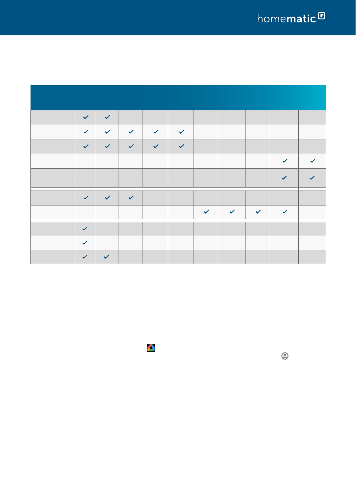
4.2.2 Use of several Access Points/device limits
The number of possible devices which can be simultaneously operated in a HomematicIP
system is determined by the number of Access Points in the system. Operation of the first
HomematicIP Access Point (HmIP-HAP) enables the use of a maximum of 80 devices. With
an additional Access Point, another 40 devices can be added, thus increasing the number of
maximum devices per installation to 120.
The Access Points act as routers and provide for maximum fail safety in the system and practi-
cally unlimited wireless range. If several Access Points are used in an installation, HomematicIP
devices now automatically select the path with the best connection quality when sending
commands or status information. This is advantageous, for example, for installations in larger
buildings or on several floors. If the Access Point is placed on the ground floor for example,
another Access Point may be used to expand the range for communication with devices on the
upper floor or in the garden house.
Figure 1:
1x HAP
Up to 80 Homematic IP
devices per installation
2x HAP
Up to 120 Homematic IP
devices per installation
Max. 2 HAPs possible per
installation
Combination and limits of Access Points
Home control by wireless technology
19
5 SETTING UP THE HOMEMATICIP SYSTEM
5.1 First steps
You can easily and intuitively set up your HomematicIP installation using the smartphone
app “ HomematicIP”; this was developed exclusively for the configuration and control of the
HomematicIP smart home system. Individual HomematicIP devices are started in operation as
presented in the respective operating instructions.
In just a few steps, your system is already installed:
Check the system prerequisites.
Install the free smartphone app.
Set up the Access Point.
Register the Access Point to the server.
You can now train by smartphone app all HomematicIP devices you want to use in your instal-
lation; you can subsequently configure your system.
5.1.1 System requirements
For setting up the system, you will need the following components:
• HomematicIP Access Point
• Smartphone with current Android or iOS version
• Router with active internet connection
5.1.2 Download the free app
The free app can be downloaded in the Google Play Store (for Android smartphones) or in the
iTunes store (for iPhones) directly to your smartphone.
• Start the HomematicIP App on your smartphone.
• Confirm the General Terms and Conditions as well as the Data Privacy Statement via
the button “Confirm” (Android) or “Accept” (iOS).
Home control by wireless technology
20
5.1.3 Set up your Access Point
The following step-by-step instructions describe the startup of a HomematicIP system by means
of a HomematicIP Access Point (HmIP-HAP).
•
L
L
AN
AN
The menu item “Set up your Access Point” is displayed in the app.
• Follow the instructions and connect your HomematicIP
Access Point using the supplied network cable to your router.
• Provide power to your Access Point using the supplied
plug-in mains adapter.
As soon as power is supplied, the Access Point establishes a connection
to the server. Dierent flashing sequences of the device LED inform
the user during set-up about the current status of the Access Point.
During the initial startup of the system, there might possibly be a direct update of the
device software (firmware) of the Access Point. This results in a more frequent change
of the device’s flashing action.
Information regarding the LED flashing sequences of the HomematicIP devices are
found in the section “Overview flashing behaviour of HomematicIP devices” on page
117.
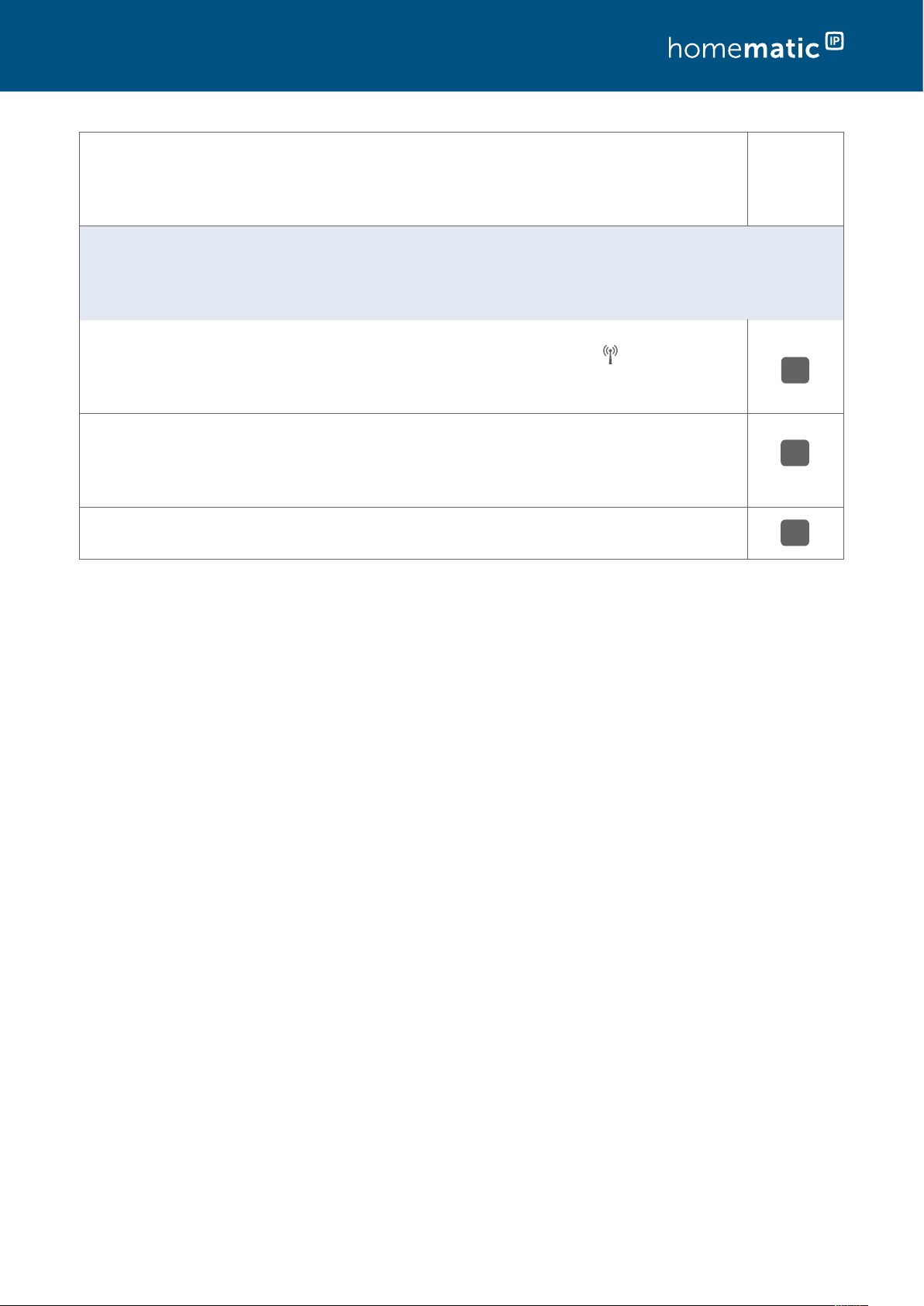
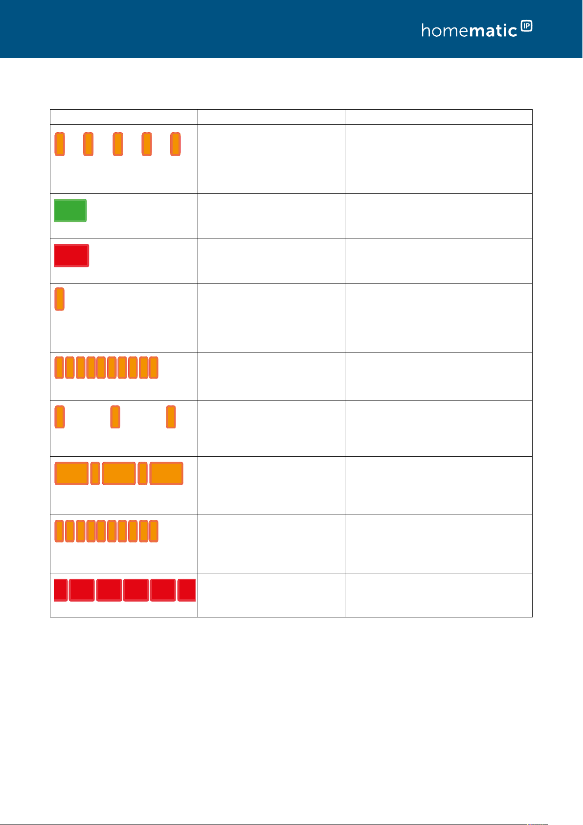
In case of an active internet connection, the flashing sequence is generally as follows upon
startup of the Access Point:
Flashing codeMeaningSolution
Permanent orange
lighting
HomematicIP Access Point starts upPlease wait until the device has
started and observe the subse-
quent flashing behaviour.
Fast blue flashingConnection to the server is being
established
Wait until the connection is estab-
lished and the LED lights perma-
nently blue.
Permanent blue
lighting
Connection to the server is being
established
Standard mode - you can continue
operation.
Additional flashing codes which can be shown via the LED of the Access Point:
Flashing codeMeaningSolution
Permanent
turquoise lighting
Connection to the server is active;
display of a secondary Access Point
Standard operation upon the use of
more than one Access Point.
Fast yellow
flashing
No connection to network or routerConnect the Access Point to the
network or the router, respectively.
Permanent yellow
lighting
No internet connectionPlease check the internet
connection and firewall settings.
Alternately long
and short orange
flashing
Update is carried out (only if required)Please wait until the update has
been completed.
Home control by wireless technology
21
5.1.4 Register Access Point to the server
If the connection to the server is established, you can register your
Access Point to the server.
• In the app, tap on the “Scan” button.
• Scan the QR code on the back of your Access Point. To this
end, position the QR code in the centre of the frame of your
QR scanner integrated in the app.
After scanning the QR code, “QR code detected” is displayed in the app for confirmation.
Alternatively, you can manually enter the individual device number (SGTIN) of your
Access Point. This can be found under the QR code on your device. To do this, tap on
the button “Enter”; enter the last four numbers of your SGTIN manually and confirm after
entering all numbers with .
• Tap on “Yes” if the device LED of your Access Point lights up permanently blue.
If this is not the case, tap on “No” and follow the instructions in the app.
• The Access Point is registered to the server. For confirmation, press the system button
of your Access Point.
• After successful registration, the Access Point is set-up immediately ready for use. Tap
on “Done” and you will get to the homescreen of the app.
With existing installations, the Access Point appears in the app’s overview of devices in the room
“Access Points” and can be moved from there into another room if necessary. The room “Access
Points” can be activated or deactivated, for presentation in the home screen, in the main menu
under settings, home screen, display of rooms. For new installations, add the Access Point to a
desired room.
You have the opportunity to adjust the brightness of the system LED on the Access Point
(0 - 100 %). To do this, go to overview of devices in the main menu and select the Access
Point there. The function “brightness system LED” is here available for configuration.
5.1.5 Adding a new smartphone
In order to add a new smartphone to an existing installation, proceed as described in the
following. Please note that the new smartphone must be close to the Access Point.
• Install the HomematicIP App on your smartphone.
• Open the app; follow the instructions. As soon as the app instructs you to, please
scan the QR code of the Access Point and press the system key. If a PIN was already
assigned beforehand for the installation, please enter it now.
• The already installed system is displayed on the new smartphone.
• Subsequently, go to settings – user overview in the main menu. You can there delete
the old smartphone, if necessary.
If you start up a new smartphone and use a backup for restoring your smartphone
profile, the HomematicIP App must first be uninstalled and subsequently reinstalled.
The data of your HomematicIP system do not get lost and, after new installation
of the app and a renewed registration with the Access Point, they will be restored.
Home control by wireless technology
22
5.1.6 Deleting a smartphone from the installation
Proceed as follows to delete a smartphone from your installation:
• Tap on the main menu symbol “... More” at bottom right on the home screen, and
there on “Settings”.
• Tap on “User overview” to view the list of all linked smartphones.
Delete the desired smartphone by swiping to the left in the relevant line (iOS) or
long-tapping on the line (Android) and then selecting “Delete”.
After deleting the smartphone, the user can no longer access the app of the HomematicIP
system.
Home control by wireless technology
23
5.2 HomematicIP App
5.2.1 Home screen
Using the button top right in the home screen, you are able to select between a tile view and a
list view.
5.2.1.1 Tile view
In the tile view, every room created is individually presented via a central tile which can be
individually covered with up to four Home favourites. In this view, all essential information of a
room are gathered at a glance. Using horizontal wipe gestures, you can swiftly and intuitively
change from room to room.
L
L
K
D
H
J
C
M
N
P
O
E
F
B
A
I
G
Q
(A)Optional: Multi Home administration (change to
another HomematicIP system while using
several Access Points)
(B)Button for changing between the tile and the list
view
(C) Operating mode for heating schedules (eco,
automatic, holiday)
(D)Alarm mode (fuzzy, presence mode, absence
mode)
(E)Local and weather information as well as display
of the values of outside sensors
(F)Window status (display about opened windows)
(G)Warning and informational notes symbols
(H)Room name
(I)Current heating schedule
(J)Room icon (adjustable via room menu)
(K) Room tile
(L) Additional rooms (view by wiping to the left or
right)
(M) Home favourites (individual adjustment for quick
access to selected functions; only available in
tile view)
(N) Home button for access to the home screen
(O) Main menu
(P)Basics (managed arrangement of basic
functions, such as PIN allocation, adjustment of
location or registering a first device)
(Q)Groups (operation of switching and shading
groups)
Home control by wireless technology
24
5.2.1.2 List view
The list view shows the rooms individually one below the other. Several rooms can be simul-
taneously clearly presented in the home screen. The nominal temperature is shown in rooms
with radiator thermostats. If a wall thermostat is installed in a room, the currently measured
actual temperature as well as the humidity are presented in addition to the nominal temperature.
Moreover, if relevant information is available, warning and information symbols are shown in
the pertinent room. Tap on the room tile to invoke other configuration settings for the room.
K
J
L
I
D
H
C
M
N
P
E
F
B
A
G
O
(A)Optional: Multi Home administration (change to
another HomematicIP system while using
several Access Points)
(B)Button for changing between the tile and the list
view
(C) Operating mode for heating schedules (eco,
automatic, holiday)
(D)Alarm mode (fuzzy, presence mode, absence
mode)
(E)Local and weather information as well as display
of the values of outside sensors
(F)Window status (display about opened windows)
(G)Current heating schedule
(H)Room name
(I)Room icon (adjustable via room menu)
(J)Display of nominal temperature in the room
(when using a radiator thermostat) as well as
actual temperature and humidity of the air
(when using a wall thermostat)
(K)
Status symbols as well aswarning and infor
mation symbols
(L) Room tile
(M) Home button for access to the home screen
(N)Basics (managed arrangement of basic
functions, such as PIN allocation, adjustment of
location or registering a first device)
(O)Groups (operation of switching and shading
groups)
(P)Main menu
Home control by wireless technology
25
5.2.2 Room menu
Tapping on the room name (both in the tile and the list view) will open the room menu. Further
adjustments can here be made for the pertinent room.
The room menu is structured according to the solution areas available for the pertinent room
(e.g. here room climate, light, shading, security). For every solution, dierent settings can be
provided, such as e.g. selection of the heating schedule.
Figure 2: Screenshot room menu
It is possible – through the selection “processing” – to provide configuration settings for the
pertinent solution, to process Home favourites (only in the tile view), change the room icon,
to rename the room, to sort anew the standard view in the room menu or to delete the room.
Tapping on “devices” will show all devices allocated to the selected room.
Home control by wireless technology
26
5.2.2.1 Determine individually the home favourites
In the tile view you are able to individually determine your home
favourites for a room. Up to four favourites can be determined per room.
This enables the control of numerous room-specific functions (e.g.
switching the lights or moving shutters up and down) directly above the
tile view.
• Tap on the room name to access the configuration menu.
• Determine via processing – processing home favourites which information in the
pertinent tile is to be presented in the home screen.
The selection of favourites diers depending on the installed system components. In
the list view, it is not possible to determine home favourites.
5.2.2.2 Changing room icon
Depending on the selected room designation, HomematicIP
allocates icons as a standard already for the various rooms. Via the
menu item “Change room icon”, you have the option to select, at
any time, its own icon for the room tile in the home screen.
5.2.2.3 Rename room
Within the HomematicIP App, there are dierent possibilities to change the name of a room.
Please proceed as follows in the room menu:
• Tap on the room name.
• Tap on “Processing” in the room menu.
• Tap on “Rename room”.
• Please enter a new name. After tap on “Confirm”, the new name will be saved.
5.2.2.4 Default view
You can determine under Processing – Default view which solution
is to be shown first (room climate, light, shading, security or access)
for the default view in the selected room when the room view is
opened.
5.2.2.5 Delete room
Within the HomematicIP App, there are dierent possibilities to delete a room. In the room
menu, use the menu item “Delete room” under “Processing”.
If there are still devices assigned to a room, you first have to delete all devices in the
device overview of the room.
Home control by wireless technology
27
5.2.3 Overview of symbols
In the device overview, as well as in parts on the home screen, certain information on the devices
is indicated via symbols.
General and status symbolsWarnings
Eco modeBattery voltage low
Cooling modeWater alarm
Party modeSabotage message
Holiday modeMotion detected
Window tiltedError messages
Door lockedRadio interference
Door unlocked/openedVoltage supply faulty
Garage door openedBus connection faulty
Garage door closedConnection to cloud faulty
Garage door in ventilation
position
Connection to Access Point
faulty
Light on
Sunset
Sunrise
Shutter/blind moved down (from
1 % shutter level)
A time profile has been allocated
to the device.
Shutters/blind moves or, respec-
tively, door lock drive is locked or
unlocked
Slat position
Multi-channel display
The device overview additionally shows to which solution a device was added. The presentation
is provided via the blue icons on the right in the list of devices ( = climate control, = light
and shade, = security and alarms, = access control, = weather and environment).
Home control by wireless technology
28
5.2.4 Pairing of devices
You can integrate, without any problems, additional HomematicIP devices into your smart home
solution. To do this, you must register, i.e. pairing, the devices at the Access Point. After you add
the devices, they appear in the app and can be configured.
You are at liberty to choose the sequence of pairing the devices. In order to keep track of things,
it is recommended to:
• proceed room after room;
• add devices bit by bit;
• install them subsequently;
• configure them conclusively.
The pairing procedure is identical for all HomematicIP devices:
• Tap on the main menu symbol “... More” on the bottom right in the home screen.
• Tap on “Add device”.
• Follow the app request “Activate device” (supply voltage to the device)
-Battery-operated devices: Insert batteries or remove insulation strips
-Power-supplied device: Plug into outlet
• If the energy supply is active, the device is displayed in the app.
• Follow the instructions in the app.
• All devices of your HomematicIP system are registered either via scanning the QR
code or by entering the last four digits of the device number (SGTIN).
• Confirm your entry with .
• In the next step, allocate the just pairing device to one or more solutions (e.g.
security, room climate and/or light and shading).
QR code and SGTIN can be found on the supplied device stickers and on the back of
the Access Point. With battery supplied devices, you will additionally find the SGTIN in
the battery compartment. Please keep the stickers in a safe place.
Devices that can be used in one solution only (e.g. the HomematicIP Radiator Thermostat)
are automatically allocated to one solution (e.g. room climate). In this case, the request
for allocation is skipped. For devices with several possible solutions (e.g. HomematicIP
Window and Door Contact), please select in which applications (e.g. room climate and/
or security) you want to use the device.
• Allocate the device to a room . Select a room that is already available or create a new
room by tapping on “New room” (Android) or “Create new room” (iOS).
• Assign a name for the device. You can optionally supplement the device name
automatically generated by the system or assign a new name.
Select the designations for devices and rooms such that a unique and unambiguous
allocation will be subsequently possible. Via the app, you have the opportunity to rename
the devices and rooms at any time.
As soon as you add additional devices, the app will suggest already existing rooms to you. Select
one of these rooms or create a new room via “New room”. The newly added device automatically
appears in the device overview of the app under the correspondingly selected room.
Home control by wireless technology
29
5.2.5 Location and weather information
Query of the location is required for utilisation of the weather data as well as the
location-dependent sunrise and sunset times.
Depending on the location of the smartphone, upon the initial setup, the time zone is set and
transmitted to the system as well as to the HomematicIP components. The changeover from
summer to winter time is eected automatically.
The app obtains the values shown via the online service OpenWeatherMap or directly via
measurements of your own HomematicIP Weather Sensors and makes them available to other
functions. Shutters / blinds / awnings are thus automatically controlled.
Via the “Sort” button at the top right of the screen you can determine the weather view order.
• Tap on “Determine weather location”. In the search field, enter the name of the city or
the postcode.
• Select the location for your weather data and tap on the left arrow at the the top left
screen and confirm your selection (Android) or tap on “Done” (iOS).
After tapping on the weather symbol, numerous location -dependent items of information will
be available to you. This includes, aside from the outside temperature, the times of sunrise and
sunset, as well as the humidity and wind velocity including the prevailing direction of the wind.
If you have additional HomematicIP products installed from the category of weather and
environment, you will be correspondingly shown additional weather data.
5.2.6 Determine system PIN
Assign a PIN for the protection of your system. By setting up a system PIN, you protect your
HomematicIP installation from unlawful access by unauthorised persons. It is thus recom-
mended to deposit a system PIN already at the beginning of the installation.
Always keep this system PIN in a well-protected place since resetting the PIN is not possible.
You will need the PIN for the following administrative functions within the HomematicIP system:
• Adding a new smartphone and deleting an existing smartphone
• Changing the PIN
• Deleting the event protocol
• Exchanging an Access Point
• Preparing couplings with additional services, such as Amazon Alexa
• Setting up access authorisations in the access solution or configuration of the
HomematicIP Door Lock Drive.
• In the field “Define PIN”, enter an at least 4-digit combination of digits of your choice.
• Tap on the left arrow at the top left screen and confirm your selection (Android) or tap
on “Done” (iOS).
After the PIN has been provided in the setup screen, the code can also be subsequently changed
in the main menu under More, Settings, PIN.
General configuration of the system
30
6 GENERAL CONFIGURATION OF THE SYSTEM
6.1 Main menu
In the main menu you can make the settings for your HomematicIP system.
• Tap on the main menu symbol “... More” on the bottom right in the home screen.
Depending on the configuration of the system, you will have the following options in the main
menu:
• General
-Device overview
-Add device
-Device updates
-Automation
-Camera
-Settings
-Info and help
• climate control
-Heating / cooling schedules
-Climate control configuration
-Holiday mode
-Hot water configuration
• Security
-Alarm protocol
-Alarm configuration
-Light groups
-Presence mode
• Light and shade
-Links/ groups
-Time profiles
-Shutter configuration
• Other information
-Automation
-Camera
-Voice control and additional services
-Multi home administration
Please note that only menu items are displayed for which devices are available in your
system. If, for example, you are not using devices of the security solution, the menu item
“Security” is not displayed.
General configuration of the system
31
6.1.1 Device overview
In the app, you manage your HomematicIP devices via the main menu symbol “... More” in the
“overview of devices”. You will find all added devices displayed, allocated according to rooms.
Devices which were paired without room allocation are displayed in a pop-up window on the
home screen.
All rooms follow in alphabetical order or in the sorting order that you specified in the settings
under the menu item “Display of rooms”.
Via a tap on “All” (Android) or “Filter” (iOS), you have the option to filter your devices according
to individual rooms.
In the overview of devices, you can adjust individual device settings. Configuration possibilities
result depending on the device. Basically, you can change – with all devices – the allocation to
a room or the name of the device.
• For this, select a device in the overview of devices. Tap on the name of the device.
• Select the menu item “Allocation” to push the device into another room and to
change the name.
Depending on the type of device, the dierent possibilities of settings are dierentiated. For
example, for devices with a push button or a rotary knob, an operating lock can be activated
or deactivated.
Devices for which the operating lock is activated can be operated only via the app, not,
however, via the device itself.
Deactivation of the operating lock is possible only via the app.
Moreover, you can adjust e.g. a temperature oset for radiator thermostats to balance out
temperature deviations. Should you operate a wall thermostat in a room, only the temperature
oset is to apply which was adjusted with the wall thermostat. For window contacts, an individual
message delay between 0 and 60 seconds can be defined.
A message delay can be useful if a window is opened only shortly without the heating to
be turned down with it.
By means of a tap on the device designation, you will find – via the infor-
mation icon at the top right of the edge of the screen – additional infor-
mation for every device in the following sequence:
• SGTIN: Individual device number
• Device type: Short designation of the device
• Current firmware: Installed firmware version of the device
• Update status: Availability of current updates for devices and
firmware
• Connection quality: Informative bar chart about the connection
quality between Access Point and device
General configuration of the system
32
6.1.2 Multi-channel view
In devices with several channels, the multi-channel view enables the allocation and designation
of individual channels to individual rooms and solutions. This concerns multi-channel devices
by HomematicIP, such as floor heating controllers, contact interfaces or multi-channel switch
actuators. After adding multi-channel devices, the allocation of individual channels to rooms
will be automatically queried.
The allocation of individual channels can be eected at any time via the display of the device
overview:
• Tap on the main menu symbol “...More” and there on “Device overview”.
In terms of devices whose channels can be allocated to dierent rooms, the already allocated
channels are displayed in the device overview under the pertinent room. One example for this
type of device are floor heating controllers which frequently control heating circuits in dierent
rooms. These channels are designated by the multi-channel symbol .
Gebruikershandleiding.com neemt misbruik van zijn services uitermate serieus. U kunt hieronder aangeven waarom deze vraag ongepast is. Wij controleren de vraag en zonodig wordt deze verwijderd.
Product:
Spelregels forum
Om tot zinvolle vragen te komen hanteren wij de volgende spelregels:
lees eerst de handleiding door;
controleer of uw vraag al eerder door iemand anders is gesteld;
probeer uw vraag zo duidelijk mogelijk te stellen;
heeft u een probleem en al geprobeerd om dit op te lossen, vermeld dit erbij aub;
heeft u een oplossing gekregen van een bezoeker dan horen wij dat graag in dit forum;
wilt u een reactie geven op een vraag of antwoord, gebruik dan niet dit formulier maar klik op de knop 'reageer op deze vraag';
uw vraag wordt direct op de website gezet; vermijd daarom persoonlijke gegevens in te vullen;
Belangrijk! Als er een antwoord wordt gegeven op uw vraag, dan is het voor de gever van het antwoord nuttig om te weten als u er wel (of niet) mee geholpen bent! Wij vragen u dus ook te reageren op een antwoord.
Belangrijk! Antwoorden worden ook per e-mail naar abonnees gestuurd. Laat uw emailadres achter op deze site, zodat u op de hoogte blijft. U krijgt dan ook andere vragen en antwoorden te zien.
Abonneren
Abonneer u voor het ontvangen van emails voor uw HomeMatic IP system bij:
nieuwe vragen en antwoorden
nieuwe handleidingen
U ontvangt een email met instructies om u voor één of beide opties in te schrijven.
Ontvang uw handleiding per email
Vul uw emailadres in en ontvang de handleiding van HomeMatic IP system in de taal/talen: Engels als bijlage per email.
De handleiding is 3.55 mb groot.
U ontvangt de handleiding per email binnen enkele minuten. Als u geen email heeft ontvangen, dan heeft u waarschijnlijk een verkeerd emailadres ingevuld of is uw mailbox te vol. Daarnaast kan het zijn dat uw internetprovider een maximum heeft aan de grootte per email. Omdat hier een handleiding wordt meegestuurd, kan het voorkomen dat de email groter is dan toegestaan bij uw provider.
Stel vragen via chat aan uw handleiding
Stel uw vraag over deze PDF
Uw handleiding is per email verstuurd. Controleer uw email
Als u niet binnen een kwartier uw email met handleiding ontvangen heeft, kan het zijn dat u een verkeerd emailadres heeft ingevuld of dat uw emailprovider een maximum grootte per email heeft ingesteld die kleiner is dan de grootte van de handleiding.
Er is een email naar u verstuurd om uw inschrijving definitief te maken.
Controleer uw email en volg de aanwijzingen op om uw inschrijving definitief te maken
U heeft geen emailadres opgegeven
Als u de handleiding per email wilt ontvangen, vul dan een geldig emailadres in.
Uw vraag is op deze pagina toegevoegd
Wilt u een email ontvangen bij een antwoord en/of nieuwe vragen? Vul dan hier uw emailadres in.