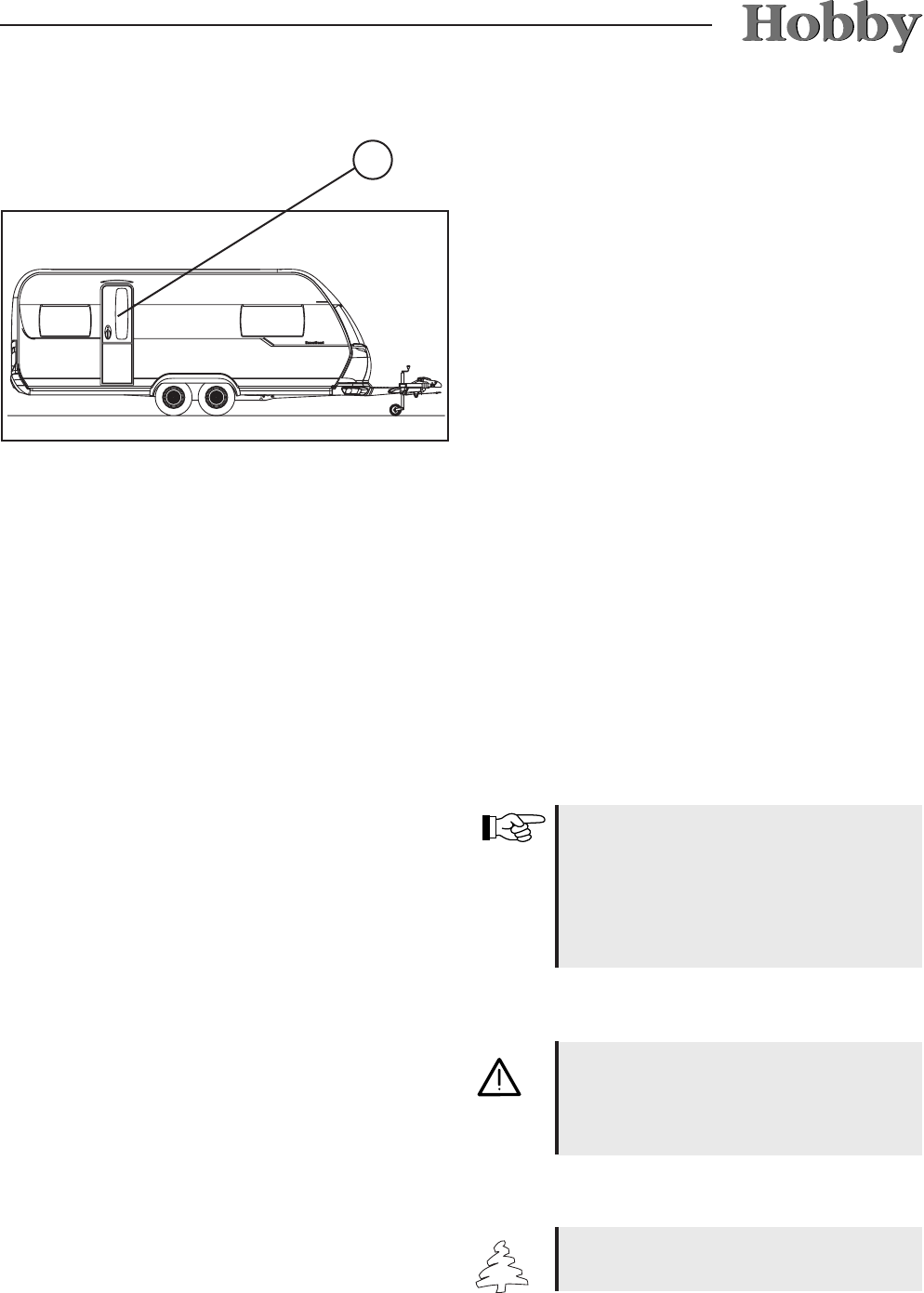
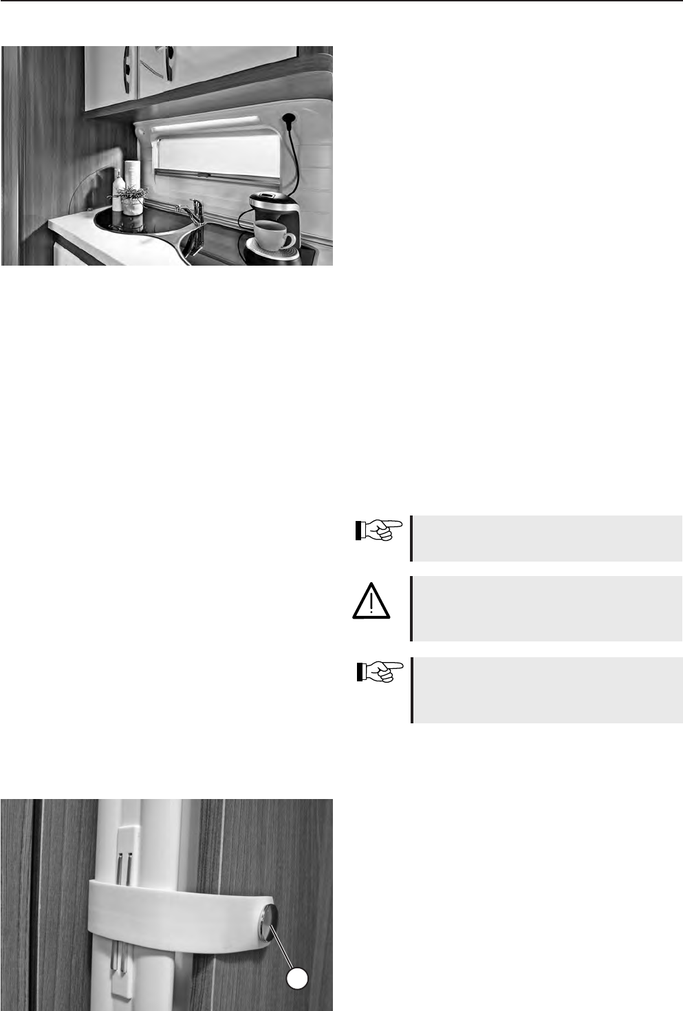
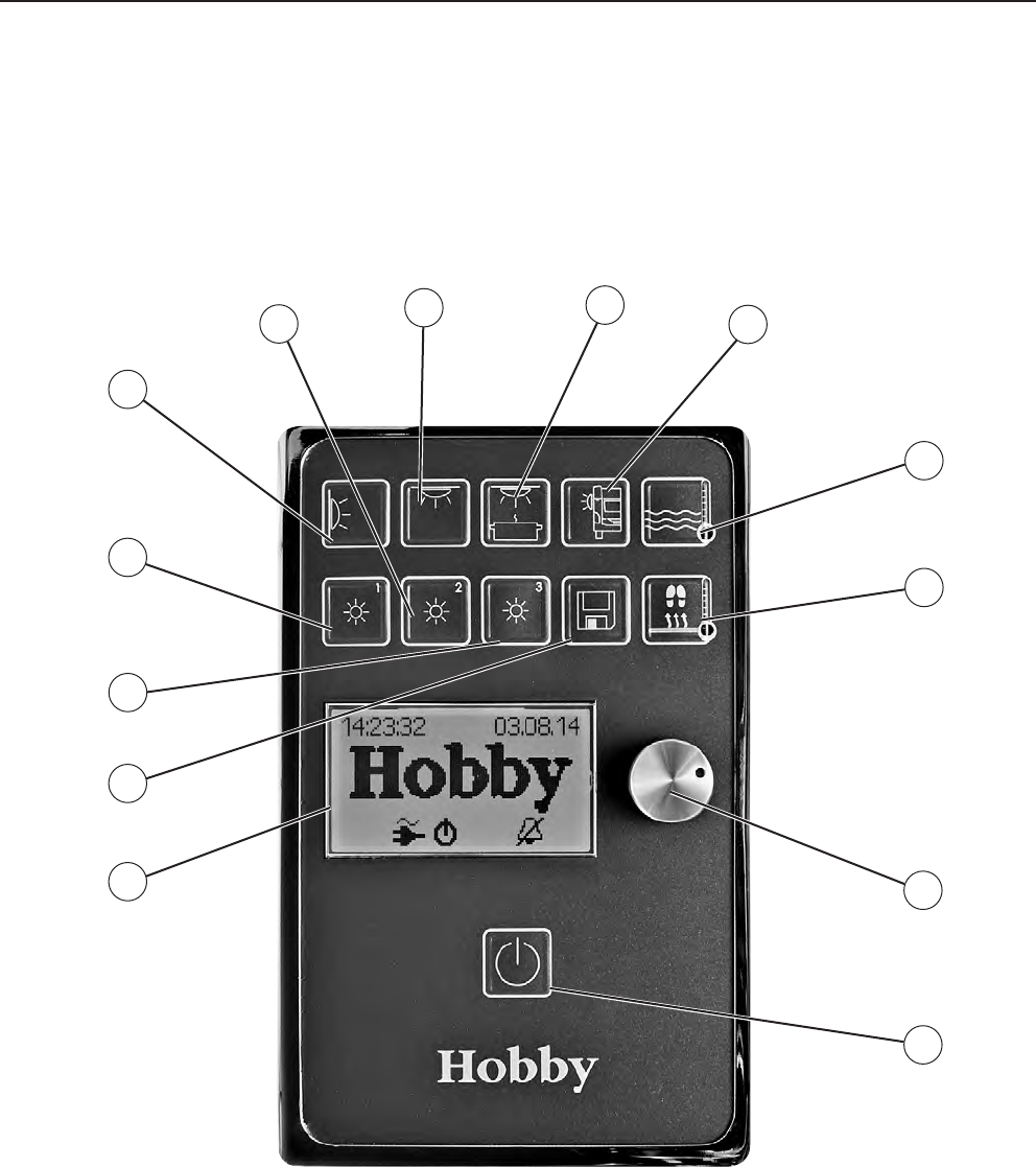
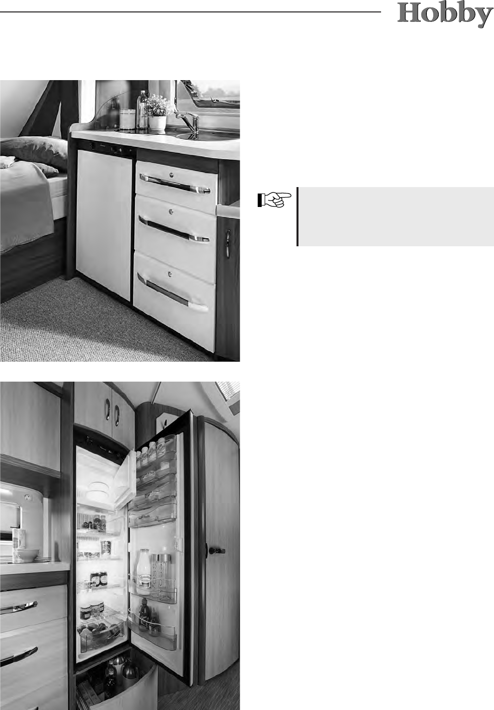
water supply, Porta Potti, refrigerator illumination
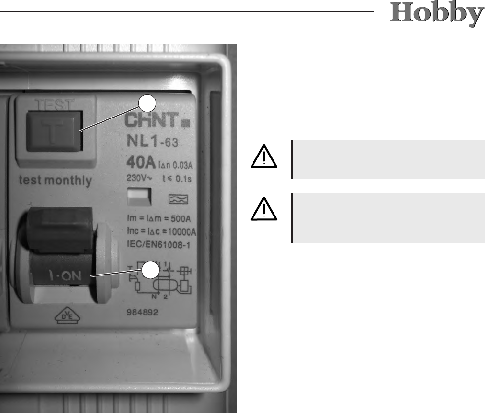
Only replace defect fuses if you know
what caused the fuse to blow and
have xed this.
In some models, there may be slight
deviations in this assignment.
Electric circuit 1 (7,5 A):
ceiling light
Electric circuit 2 (7,5 A):
dependent on the model
Electric circuit 3 (7,5 A):
right hand bed, kitchen, shower
Electric circuit 4 (7,5 A):
washstand, outer tent light, left hand bed
Electric circuit 5 (7.5 A):
water pump
12345
12345
De Luxe/Excellent/Prestige/Premium/
Landhaus
De Luxe easy
07-26
Only replace defect fuses if you know what
caused the fuse to blow and have xed this.
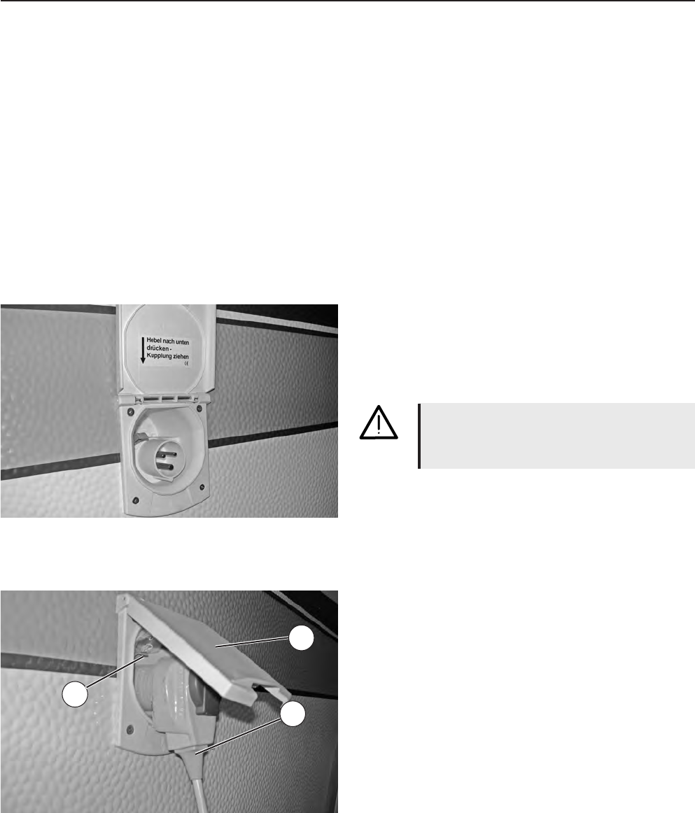
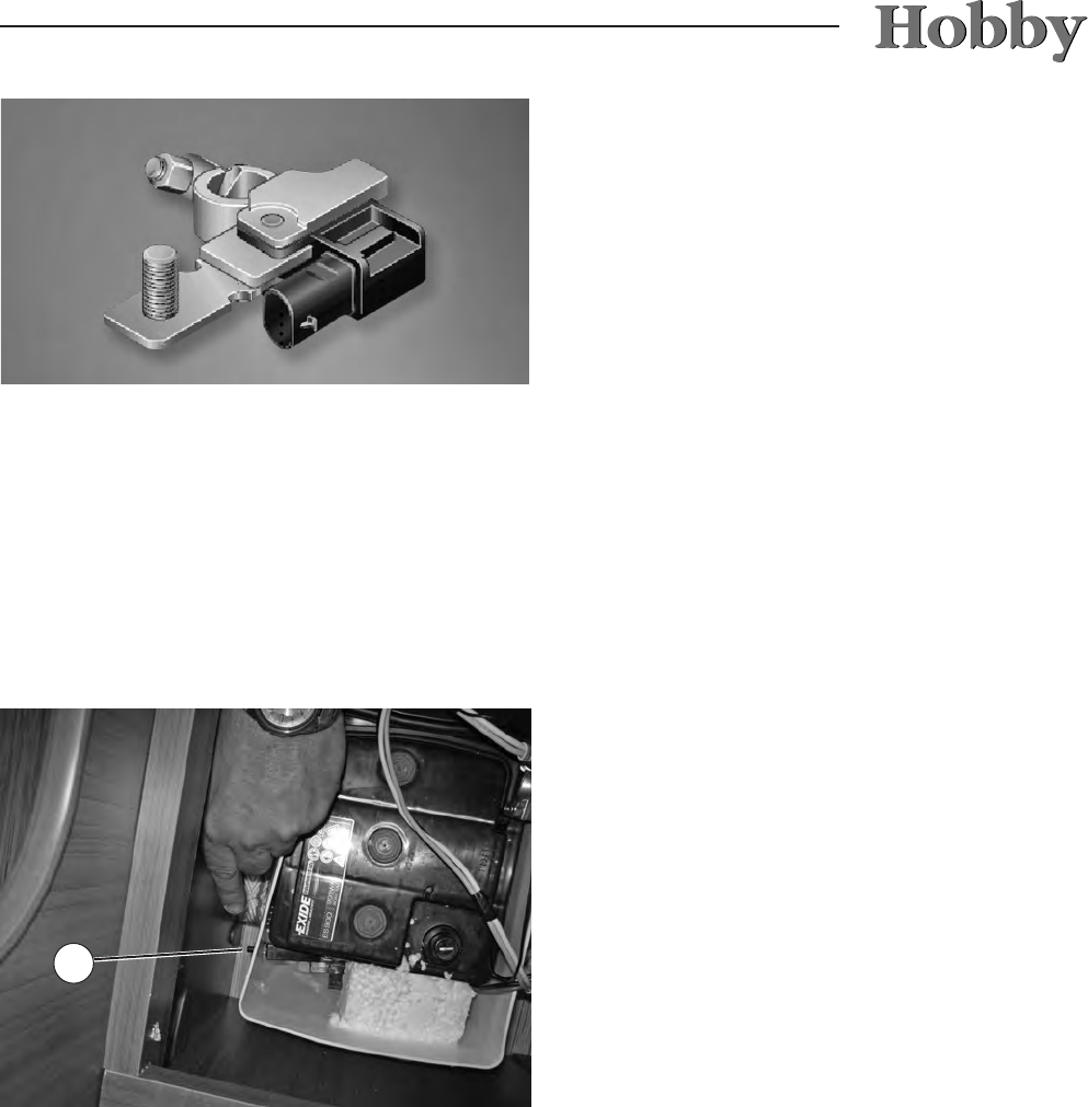
Your caravan also has a combined external so-
cket and antenna terminal in the outer tent
(optional extra for De Luxe and De Luxe easy).
This can be used, for example, to set up a TV
in the outer tent. Depending on how you wire it,
the integrated antenna terminal can be used as
either an input or an output socket. For further
information, please speak to your Hobby dealer
(also see 6.2).
07-27
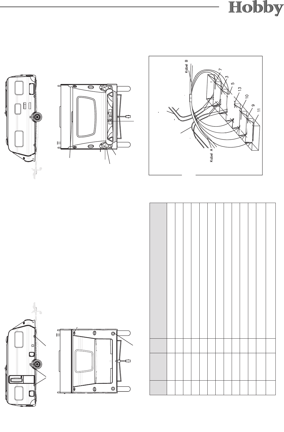
7.5 External circuit diagram
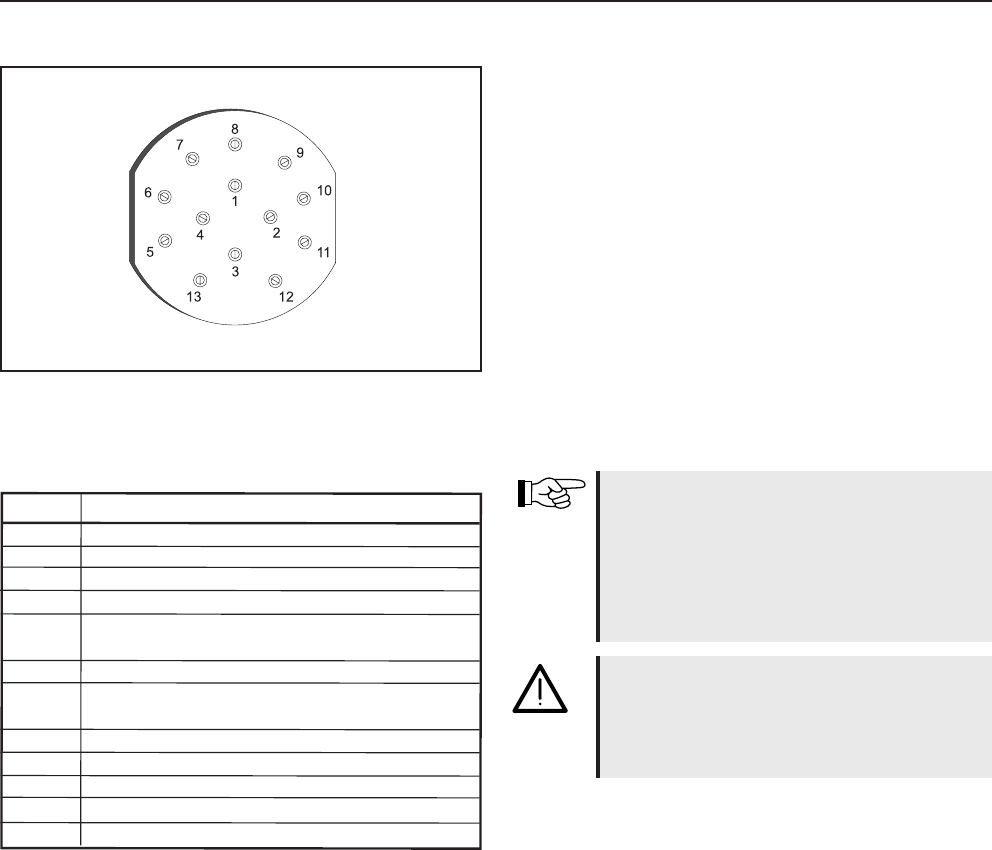
r e h c u a r b r e V t t i n h c s r e u Q e b r a f r e d A N I P
² m m n i
s k n i l , r e g i e z n a s g n u t h c i r t r h a F 5 , 1 b l e g 1
e t h c u e l ß u l h c s l e b e N 5 , 1 u a l b 2
) 8 s i b 1 s i e r k m o r t S r ü f ( e s s a M 5 , 2 ß i e w 3
s t h c e r , r e g i e z n a s g n u t h c i r t r h a F 5 , 1 n ü r g 4
g n u t h c u e l e b n e h c i e z n n e K d n u e t h c u e l s g n u z n e r g e B , e t h c u e l ß i r m U , e t h c u e l ß u l h c S e t h c e R 5 , 1 n u a r b 5
n e t h c u e l s m e r B 5 , 1 t o r 6
g n u t h c u e l e b n e h c i e z n n e K d n u e t h c u e l s g n u z n e r g e B , e t h c u e l ß i r m U , e t h c u e l ß u l h c S e k n i L 5 , 1 z r a w h c s 7
r e f r e w
n i e h c s r h a f k c ü R 5 , 1 e g n a r o 8
) s u l p r e u a D (
g n u g r o s r e v m o r t S 5 , 2 u a l b 9
t r e u e t s e g r e t l a h c s d n ü Z , g n u g r o s r e v m o r t S 5 , 2 ß i e w / u a l b 0 1
0 1 r ü f e s s a M 5 , 2 t o r / ß i e w 1 1
3 n o v e s s a M g n u n n e k r e r e g n ä h n A 5 , 1 t t e l o i v 2 1
9 r ü f e s s a M 5 , 2 u a l b / ß i e w 3 1
Side positioning light 5W
Red clearance light 5W
Front running light with
reector 5W
LED brake lights
Red clearance light 5W
Route-indicating signal 21W
brake lights 21W
Taillight 10W
Rear fog light 21W
Number plate light 5W
PINPIN
Wire colour
mm
2
Consumer
1yellow1,5Route-indicating signal, left
2blue1,5Rear fog light
3white2,5Mass (for electric circuit 1-8)
4green1,5Route-indicating signal, right
5brown1,5Right taillight, clearance light, running light and number plate light
6red1,5Brake lights
7black1,5Left taillight, clearance light, running light and number plate light
8orange1,5Reverse light
9blue2,5Electric power supply (steady plus)
10blue / white2,5Electric power supply, ignition-controlled
11white / red2,5Mass for 10
12violet1,5Trailer number plate, mass from 3
13white/blue2,5Mass for 9
Distribution box 12V
Side positioning
light, left
Side positioning
light, right
Positioning and
clearance light, left
Positioning and clea-
rance light, right
black
white
brown
white/blue
blue/white
blue
white/red
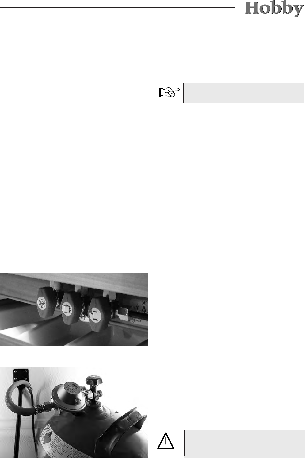
12 V Electrical Installations in the Vehicle,
using the De Luxe easy model as an example
07-28
Contact assignments may differ slightly
in some models.
S37
34
35
36
1234
S41
+ +--
+ -
38
39
40
1
+ -
+ -
2
3
18
4
5
23
6
11
12
7
21
19
26
27
22
9
De Luxe easy
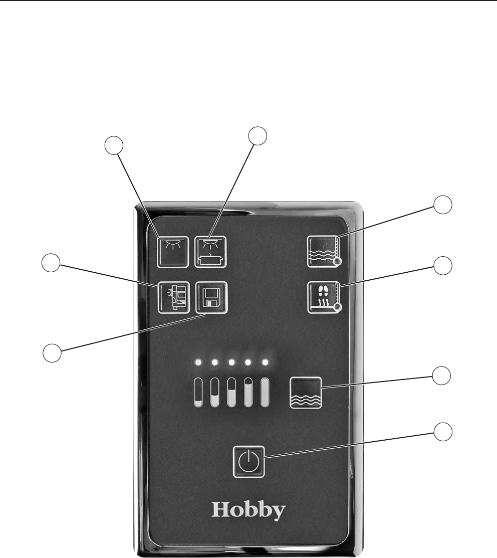
7.6 Contact plan for the light control system
230V current range
Therme
Floor heating
Input lead
Protective
conductor
S40 10/11 from plus
terminal ignition
circuit
S39 to charge controller,
control RE+-
(only self-sufcient / 12V)
Plus electrical supply
S38 to charge controller,
input 1 charging current
(only self-sufcient / 12V)
9 and 13 from car or
connection to charge controller,
battery connection for self-sufcient / 12V
Fuses 7,5A
Bridge circuit
from S37 to 4
S37 earth connection to PE4
Jumper 1
closed for
self-sufcient / 12 Fz
Connection for external keys
Battery monitoring control
Main panelBathroomBedBedRadioKitchen
Shower
Ceiling
light
Washstand
right-hand
bed
Kitchen
Outer tent
light
left-hand
bed
Earthing
electrical
supply
07-29
S37
7,5A
34
35
36
1234
S41
+ +--
+ -
38
39
40
1
+ -
+ -
2
3
18
30
31
32
33
8
13
4
9
14
5
10
15
23
6
11
16
12
7
17
21
19
20
24
28
25
26
27
29
22
7,5A7,5A7,5A15A
230V current range
Therme
Floor heating
Input lead
Protective
conductor
S40 10/11 from plus
terminal ignition
circuit
S39 to charge controller,
control RE+-
(only self-sufcient / 12V)
Plus electrical supply
S38 to charge controller,
input 1 charging current
(only self-sufcient / 12V)
9 and 13 from car or
connection to charge controller,
battery connection for self-sufcient / 12V
Fuses
Bridge circuit
from S37 to 4
S37 earth connection to PE4
Wall light
dimmerr
Ceiling
light
dimmer
Children's
bedside
lights III
Children's
bedside
lights
Clothes
cupboard
light
Fan
Water
supply
For WLU: left
bed
Porta
Potti
For WLU:
clothes
cupboard
light II
Clothes
cupboard
roof cable
Clothes
cupboard
roof cable
Clothes
cupboard
roof cable
Outer tent
light
Washstand
Shower
Jumper 1
closed for
self-sufcient / 12 Fz
Dimmer for
left-hand
bed
Dimmer for
right-hand
bed
Connection for external keys
Battery monitoring control
Main panelBathroomBedBedRadioKitchen
Contact assignments may differ slightly
in some models.
Ambiente
2a
Kitchen
Ambiente
2b
Ambiente
3a
Ambiente
3b
Ambiente
3c
Ambiente
1a
Ambiente
1a
Ambiente
1b
De Luxe/Excellent/Prestige/Premium/Landhaus
Earthing
electrical
supply
07-30
Children‘s bed light is switched on and off by
turning the bear‘s nose.
This light can be dimmed and set as a night light
(„blue ears“ - cannot be switched on the control
panel). The night light is switched on and off
separately by means of a switch underneath the
children‘s bed light.
The clothes cupboard light
l
is switched on
and off by opening the doors of the cupboard
(integrated contact switch - cannot be switched
on the control panel). The LED light is battery-
operated. Before initial operation, pull off the foil
that prevents battery contact.
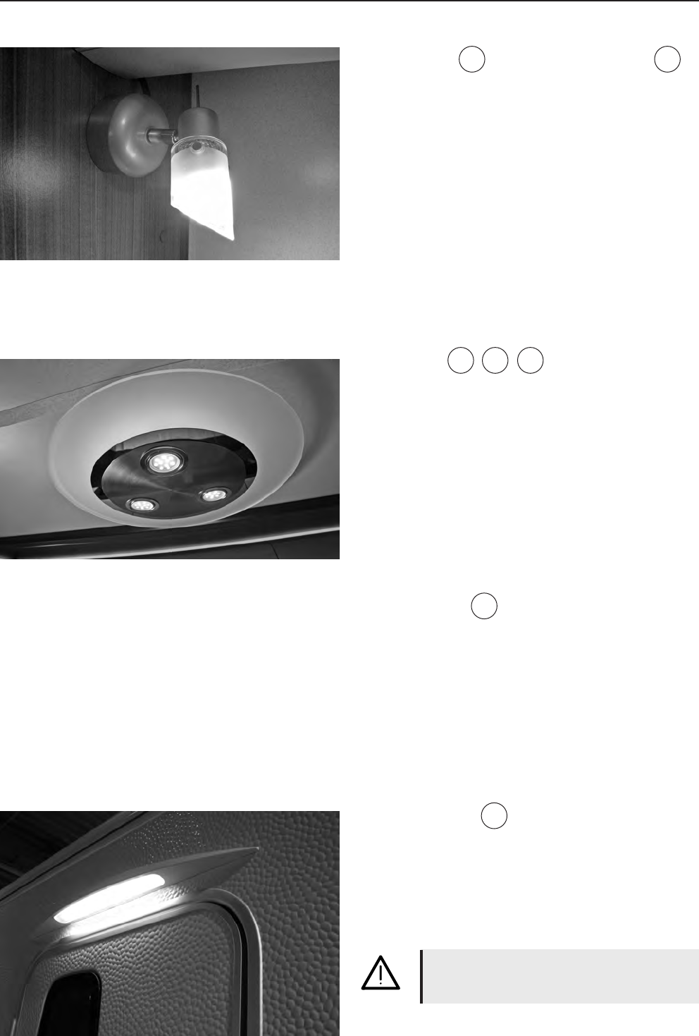
Corner lights
Spotlight
j
and integrated lighting columns
k
can be switched separately.
7.7 Special Lights
The switches for the lights described here are
located directly on the lights themselves; they
are not controlled via the control panel.
1
2
3
08-1
8. Water
8.1 General information
Function of the water supply
Water is provided to the kitchen and toilet area
via an immersion pump. The immersion pump
functions on electricity:
- via a 12 volt automobile battery if the caravan
is connected via a plug to the base vehicle,
- via a transformer if the caravan is connected
to the 230 volt main.
- In self-sufcient mode * via the installed auxi-
liary battery.
Rules for the immersion pump
• The immersion pump is only suitable for water.
• The immersion pump tolerates temperatures
up to 60° C for a short time.
• Avoid dry runs.
• Protect the pump from freezing.
• Hard blows or hits as well as very dirty water
can destroy the pump.
Please note
• Water that is suitable for drinking should
always be used with working with food. This
also applies to washing your hands and clea-
ning the objects that have come into contact
with food.
• To ensure that the quality of the water is fault-
less, the water should be taken directly from
the public drinking water system.
• Under no circumstances should garden ho-
ses, watering cans and similar materials that
are unsuitable for drinking water be used to
ll the mobile system.
• If the caravan will not be used for a longer
period of time, the entire water system must
be emptied completely.
• After long periods of stagnation, the water
system must be rinsed thoroughly before it is
used again. If you nd that it is contaminated,
the material should be disinfected using clea-
ning agents that are permitted and suitable.
We recommend that you inspect
any water you have left in the tank,
this is very critical before using the
water again.
08-2
8.2 Water supply
Rolling waste water tank
The rollable waste water tank
m
can be pushed
beneath the vehicle when the caravan is stati-
onary. It collects the waste water and holds 24
litres. The waste water tank can be transported
on wheels and has an extendable transport
handle
l
, allowing you to transport it to the
appropriate waste disposal place for emptying.
4
5
Built-in fresh water tank
The tank
j
has a model-specic volume of 25
or 50 litres.
The tank is lled with fresh water by means of
the ller neck
k
on the side wall.
The fresh water ller neck is identied by a blue
screw cap as well as a water faucet symbol on
the lower edge of the frame. The screw cap is
opened and closed by means of the enclosed
key for exterior ap locks and the door of the
structure.
Should the tank overow, the excess water is
drained off underneath the vehicle by means of
an overow.
The water can be emptied from the tank by un-
screwing the overow pipe
l
.
1
3
3
2
08-3
Empty the waste water tank before
beginning your journey and then use
the belt in the gas-bottle container to
secure it.
Empty the waste water tank if there
is danger of frost.
Never pour boiling water into the
sink drain. This can lead to deformi-
ties and leakages in the waste water
system.
Only empty the waste water tank at
waste disposal stations, camping
grounds or specially marked waste
disposal facilities.
During the trip, the waste water tank
m
can be
stored in the gas-bottle container to save space.
Exception: In the Landhaus model, the waste wa-
ter tank is stored under the queen-size bed (acces-
sible via the service ap).
Filling the water system
• Place the caravan in a horizontal position.
• Switch on the main switch on the control panel.
• Shut the outlet valves on the therme.
• Shut all of the water taps.
• Unlock the petrol cap
o
and turn it counter-clo-
ckwise to open it.
• Fill the water tank using the fresh water ller neck.
• Turn all of the water taps to „hot“ and open them.
The water pump will be switched on.
• Leave the water taps open until the water ows
out of the taps without any bubbles. This is the
only way to ensure that the therme will also be
lled with water.
• Turn all of the taps to „cold“ and leave them open.
The cold water pipes will be lled with water.
• Leave the water taps open until the water ows
out of the xtures without any bubbles.
• Shut all of the water taps.
• Shut the ller neck.
Use the control panel to check the
amount of water in the fresh water
tank.
6
4
08-4
To remove water
•
The water will be mixed to the desired
temperature according to the position of the
pre-mixing unit.
Emptying the water system
• Use the control panel to switch off the electrici-
ty for the water pump
p
by pressing the main
switch for a longer period of time (4 sec.).
• Open all of the water taps
q
to the centre
setting.
• Hang up the adjustable shower head in the
shower.
• Open the outlet valves
o
on the therme.
• Unscrew the cap on the cleaning port of the
fresh water tank
j
.
• Unscrew the overow pipe
k
in the fresh
water tank.
• Remove the lid of the water tank. Take out
the water pump and hold it up until the water
pipes have emptied completely.
• Check whether the tank, therme, faucets and
pipes have emptied completely. If necessary,
blow out any remaining water in the pipes
using compressed air (max. 0.5 bar).
• Re-insert the overow pipe and the water
pump in the fresh water tank and close the
openings.
• Leave the faucets
q
and the outlet valves
o
open.
Hot water supply
• Use the control panel to switch on the ther-
me. The temperature of the water is regulated
by means of a thermostat via 230V mains
supply to 55° C.
• The therme will hold approx. 5 litres.
• If you have turned on the heating system, the
water in the therme will also be heated by the
air circulation of the heating; in self-sufcient
mode, it will be heated solely in this manner.
Rules for the therme
•Use the control panel to switch off this equip-
ment whenever the caravan is not in use.
Plan for warm water supply
8
7
6
6
08-5
•
Empty the therme at the risk of frost. Frozen
water can cause the therme to burst!
•A depressuriser must be used if the pump is
connected to a central water supply, or on
stronger pumps. The pressure in the therme
may not exceed 1.2 bar. In addition, a safety
valve or runoff valve must be used in the cold
water tap.
Never operate the therme electrically
when it is empty.
Please also note the manufacturer‘s
separately enclosed operating in-
structions.
Hot-water function in the shower in
Premium vehicles
•
The shower regulator in the Premium vehicles
rst regulates the amount of cold water up to
a certain point.
If you turn the regulator beyond this point,
you will get hot water.
However, the amount of hot water
can then no longer be regulated. This
is only possible when the regulator is
turned to cold water.
08-6
8.3 Boiler *
The optional boiler holds approx. 14 litres of
water. It uses gas to heat the water or, depen-
ding on the model, there is also an option to heat
it electrically using an integrated heating rod. It
replaces the standard Truma therme.
Before each journey, make sure the
boiler has been switched off and then
attach the chimney cap.
Before operating the boiler you must
remove the chimney cap.
Empty the boiler if there is a danger of
frost.
Never operate the boiler if it is empty.
Should you operate the cold water
system without the boiler, the boiler
will also be lled with water. To avoid
damage due to frost, empty the con-
tents even if the boiler has not been
used.
Filling the boiler
• Shut the outlet valve on the cold water intake
pipe. Set the lever in a horizontal position.
• Switch on the energy supply by pressing the
main switch on the control panel.
• Open at least one faucet and leave it open
until the boiler has been lled by displacing
the air and the water ows.
• Shut the faucet.
Emptying the boiler
• Use the control panel to switch off the energy
supply.
• Open the faucets in the kitchen and the ba-
throom.
• Open the outlet valve on the boiler. Set the
lever in a vertical position.
• Empty the water directly outside.
08-7
Operating on gas
• Remove the chimney cap.
• Open the gas bottle and the emergency shut-
off valve on the gas pipe.
• Use the rotary switch on the control panel to
switch on the boiler. The green control light
will shine.
• Use the rotary switch to set the desired tem-
perature (approx. 30° C – 70° C).
Operating on electricity
• Use the control panel to switch on the
boiler. The control light will shine.
When operating on electricity, it is
not possible to preselect the water
temperature. This is automatically
set to approx. 70° C.
Switching off the boiler
• Use the rotary switch to turn off the boiler.
• Attach the chimney cap and close the emer-
gency shutoff valve and, if necessary, the gas
bottle (only when operating on gas).
30
40
50
60
70
Boiler
Boiler EL
230 V ~
When operating on electricity, the
boiler functions only when the
caravan is connected to the 230 V
mains supply.
08-8
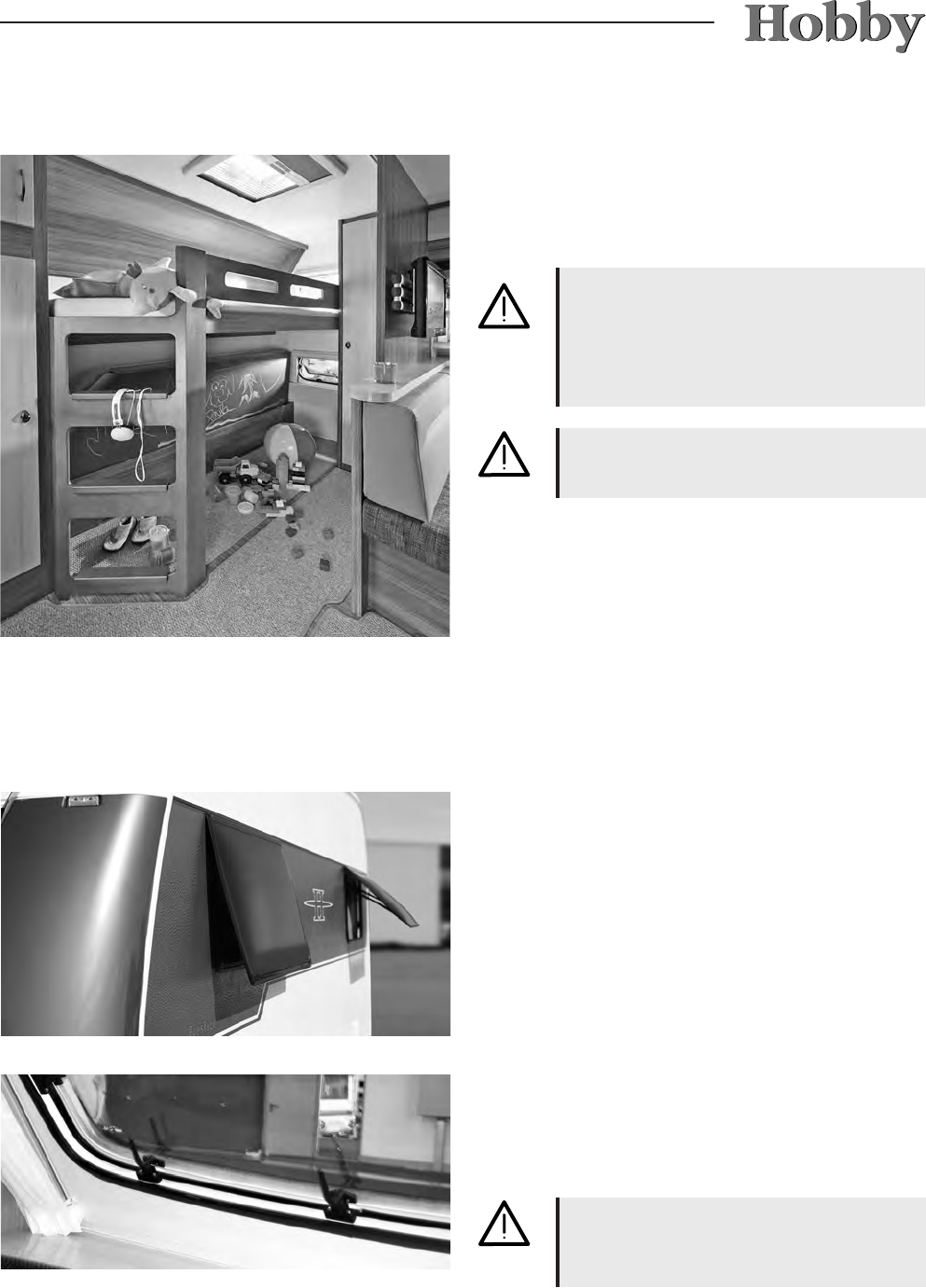
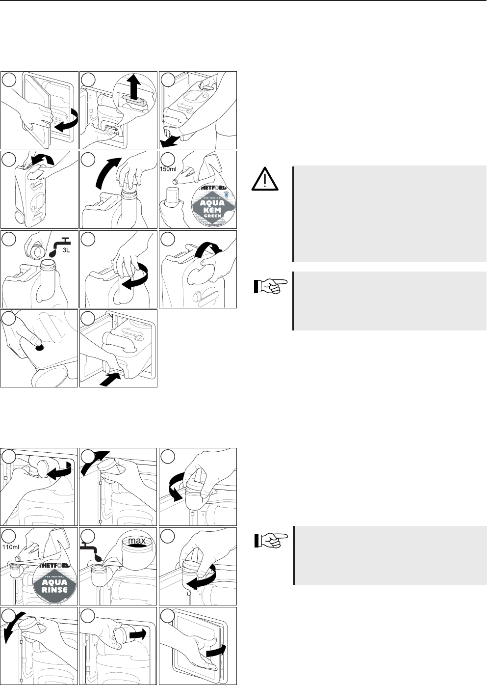
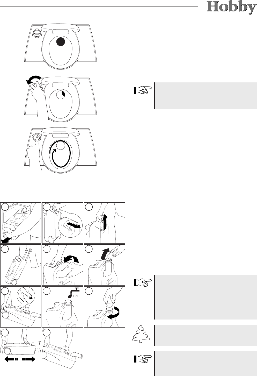
8.4 Toilet
Preparing the excrement tank
Before you can use the toilet, you must rst pre-
pare the excrement tank. How to do this is shown
in Figures 1 to 11 on the left.
Never add sanitary liquids directly
through the valve or into the toilet bowl,
because this may damage the washer
of the valve in the excrement tank.
Always add liquids through the empty-
ing support (Fig. 6).
We recommend that you press the
ventilation button (Fig. 10) before
putting the excrement tank back into
its correct position.
Preparing the ushing water tank
The next step is to prepare the ushing water
tank as shown in Figures 12 to 20.
To avoid water damage in your cara-
van, ensure that you are not travelling
with a ushing water tank that is too
full (Fig. 16).
Check the emptying hose or the lling level indi-
cator on the adjusting knob (C-500 only) to deter-
mine how much water is in the tank.
123
456
789
10
11
121314
15
1617
1819
20
08-9
Using the toilet
The toilet can be used when the valve is either
open or closed. To open the valve, turn the con-
trol knob counter-clockwise or push the lever to
the left (depending on your model).
Never leave any water in the bowl
when the toilet is not being used.
This prevents unpleasant odours.
Flush the toilet by pressing the ush knob for
several seconds. Shut the valve every time you
have nished using the toilet.
Emptying the excrement tank
The excrement tank has a capacity of approx.
19 litres. It must be emptied when the lling level
indicator lights up red. Once this lights up, the
tank can be used no more than two times.
Ensure that the valve is closed, open the Porta
Potti ap and follow the instructions shown in
Figures 21 to 31 on the left.
To empty the tank without spraying,
press the ventilation button while
you are emptying the contents of the
tank. Only press the ventilation but-
ton when the emptying support is in a
downward position!
Empty the excrement tank only in
special places for sanitary disposal.
Please refer also to the
manufacturer's operating manual,
included in this package.
21
2223
242526
272829
3031
08-10
09-1
9. Gas system
9.1 General safety rules for the use of liquid gas
facilities
Inspection of the gas facilities
•Have the gas facilities checked by an expert
before the rst use.
•The gas facilities should be inspected by
an expert every two years. This inspection
should be documented on the inspection cer-
ticate in accordance with the German Asso-
ciation of Gas and Water Experts, worksheet
G 607, and EN 1949.
•Regulator knobs, hoses and waste gas out-
lets should also be inspected.
•We recommend that you replace the safety
regulator knob and hose pipes fter 10 years at
the latest.
•The owner/operator is responsible for arran-
ging the inspection. This also applies for ve-
hicles that are not licensed to drive on public
roads.
Installations and modications
•Installations and modications may only be
conducted by an expert.
•Only devices with a uniform inlet pressure of
30 mbar may be operated.
• Any change in the gas facilities requires a new
inspection by an expert and written documen-
tation of this inspection.
Regulator knobs and valves
•Only use those regulator knobs custom-made
for vehicles, with a safety valve. Other regula-
tor knobs are not permissible in accordance
with the German Association of Gas and Wa-
ter Experts, worksheet G 607, and EN 1949.
They are not sufcient to tolerate the im-
mense strain.
The gas operation pressure is
30 mbar.
Connections on gas pressure regu-
lators are screwed on counterclock-
wise.
09-2
Before rst use
•
Ventilation openings should remain unob-
structed.
•If necessary, remove snow from the ue.
•Remove any dirt and snow/debris mixture
from the suction openings under the vehicle
oor; otherwise, the levels of carbon mon-
oxide could increase to dangerous levels.
•The safety ventilation openings may not be
closed.
•We recommend that you keep a re extin-
guisher that uses drying powder, with a capa-
city of at least 1 kg, by the entry door, as well
as a re blanket by the cooker. Ensure that
everyone is familiar with the re prevention
measures on site (see also 2.1 General infor-
mation).
Read the operating instructions from
the manufacturer carefully.
Never use portable cooking or hea-
ting equipment, except for electrical
heating equipment (note the power
consumption), but not radiant hea-
ters, because these may cause a re
or risk of suffocation.
• Pressure regulators must have a xed output
pressure of 30 mbar. The requirements of EN
12864, Appendix D, apply accordingly. The
regulator must have a rate of ow of 1.2 kg/h.
•Connect the regulator knobs very carefully by
hand. do not use keys, pliers or similar tools.
•Use the de-icing system (Eis-Ex) for the
regulator knobs when the temperature drops
below 5° C.
09-3
The caravan is equipped with propane gas
facilities. These facilities opeate the following
devices:
-cooker
-refrigerator
-heating element
-warm water boiler, if necessary
-special equipment, if necessary
- baking oven, if necessary
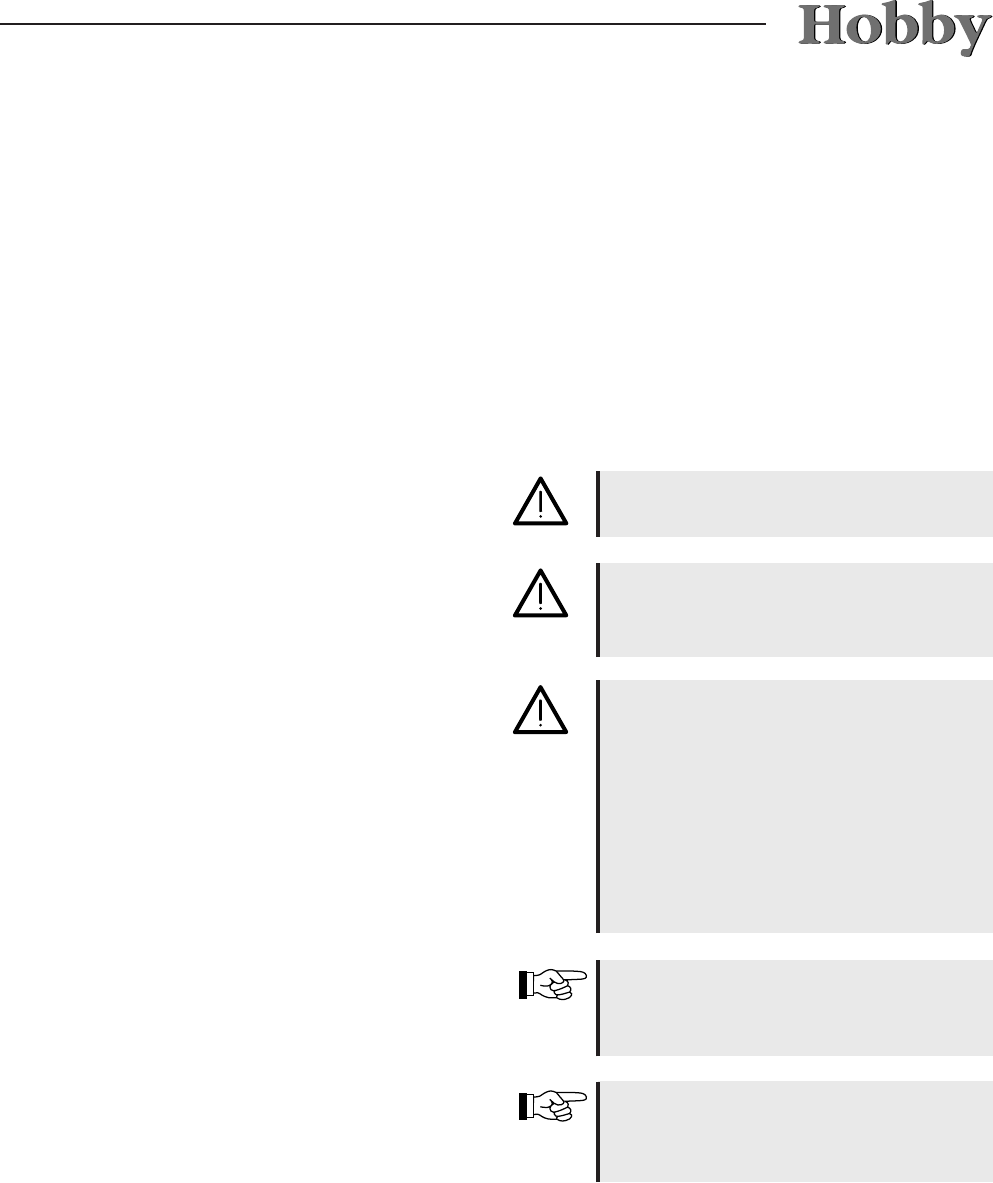
9.2 Gas supply
2
1
3
4
5
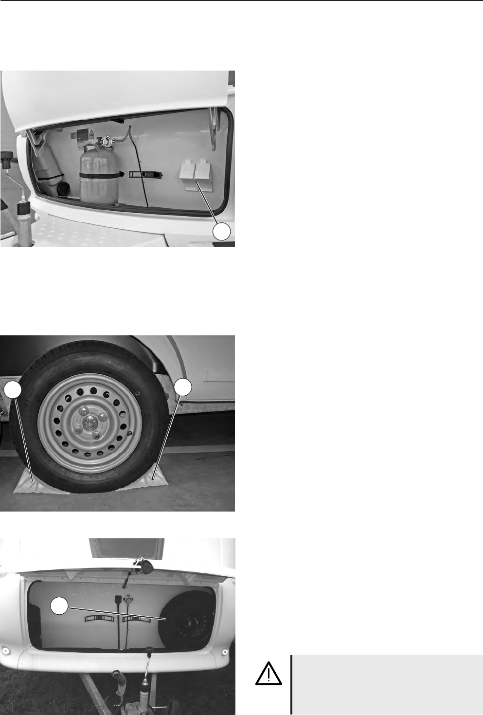
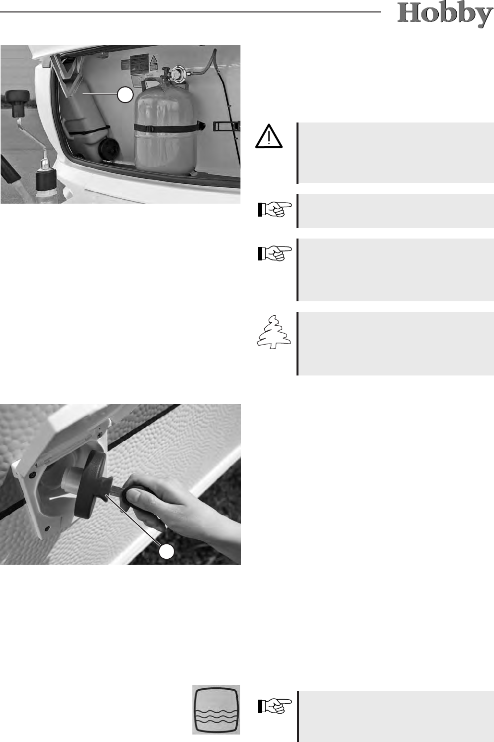
Bottle container
The gas bottle container holds two 11 kg pro-
pane cylinders
j
. Via a safety regulator
k
, the
gas bottles are attached by a hose
m
to the
supply line
n
. Each bottle is fastened by two
separate belts
l
to the oor of the gas bottle
container and the wall at the front end of the
caravan.
Rules for the gas-bottle container:
•Before every trip, check that gas bottles are
securely fastened. Place them in an upright
position and shut the valves.
•Re-lash all loose belts.
•Using a leak indicator, inspect the regulator
connection for leaks every time you change a
bottle.
•The gas-bottle container is not suitable for
transporting accessories (e.g. outer tent).
• The main shutoff valves on the gas bottles
must always be easily accessible.
•The ventilation of the gas-bottle container
(gap between the bottom of the bottle contai-
ner and the front wall) must not be closed.
• Lock the gas-bottle container to prevent un-
authorised people from obtaining access.
Gas bottles may only be carried in
the gas-bottle container.
Gas bottles must be closed whene-
ver you are driving.
09-4
Changing gas bottles
•Open the ap of the gas-bottle container.
•Shut the main shutoff valve on the gas bottle.
•Manually unscrew the gas pressure regulator
and gas hose from the gas bottle (left-handed
thread).
•Loosen the belts and remove the gas bottle.
• Put full gas bottle back in the bottle container.
•Lash belts securely.
• Manually screw gas pressure regulator and
gas hose onto the gas bottle (left-handed
thread).
• Close the lid of the gas-bottle container.
Never smoke or light open res when
changing gas bottles. After changing
bottles, check whether gas is escaping
from the points of attachment by spra-
ying these with a leak indicator.
Shutoff spigots and valves
The gas circulation to the corresponding device
can be cut off with these spigots. The spigots
are marked with stickers for the corresponding
devices.
Place of installation of gas shutoff spigots
• These are located in the kitchen in the upper
drawer.
Rules for shutoff spigots and valves:
•Close all spigots on gas-powered devices
during the drive.
• The gas shutoff spigots shown on the adjoi-
ning photos are closed. To open the valves,
they must be turned to a vertical position.
• No inammable devices may be in operation
when lling the petrol tank of the base vehi-
cle, on ferries and in the garage.
If you suspect a leak in the gas
system, you must immediately close
all the shutoff spigots in the caravan
and the gas bottle valves in the bottle
compartment.
If you suspect leaks, have your
dealer or another expert inspect for
leaks.
Such an inspection may never be
conducted in the presence of open
ames.
The symbols on the gas shutoff spigots
have the following meanings:
Heating
element
Baking
oven
Gas
range
Refrigerator
09-5
The external gas socket can be used for connec-
ting gas devices (such as the barbeque).
When hitching, the plug connection is plugged
into the safety coupling. The plug connection
can only be hitched when the emergency shutoff
valve
j
has been closed. Push back the clutch
sleeve to undo the safety latch.
9.3 External gas socket*
• The operating pressure of devices to
be connected must be 30 mbar.
• Maximum performance of devices to
be connected: 1.5 kW
Shut the cap
k
of the valve opening
when the clutch is not in use.
1
2
09-6
10-1
10. Built-in devices
10.1 General information
In this chapter, you will nd information on the
devices that have been built into the caravan.
This information refers only to the operation of
these devices.
For further information on the individual built-in
devices, please refer to the separate operating
instructions that have been included in the blue
service bag found in the vehicle.
Built-in devices may only be repaired
by specialists.
Only the device manufacturer‘s origi-
nal spare parts may be used for main-
tenance and repair work.
Any changes to the built-in devices as
well as non-compliance with the rules
for use will cause the guarantee to
become void and lead to the exclusi-
on of liability claims. Furthermore, the
operating licence for the device will
become void and, in some countries,
this means that the operating licence
for the vehicle is also void.
Please also refer to the instructions in
Chapter 9 for operating gas devices,
gas regulators and gas bottles.
Please observe the instructions in
Chapter 7 for operating electrical
devices.
10-2
10.2 Hot-air heating
Place of installation
-In the closet or the corner of the ue
Before rst use
•
Several air outlet nozzles have been built into
the caravan. Pipes lead the hot air to the air
outlet nozzles. Turn the nozzles so that the
hot air is expelled where you want it.
• Check whether the ue is unobstructed. Any
covers must always be removed.
•Before the rst ignition, ensure that the bat-
teries in the automatic ignitor are working
properly.
Heating while driving is forbidden.
Should there be any difculty, please
wait at least 3 minutes before re-at-
tempting ignition; otherwise, there is a
danger of explosion.
The space behind the heating may
not be used as stowage space.
To operate
•Open the bottle valve and the quick-close
valve in the gas line.
•Turn the operation handle
j
to the thermo-
stat position 1-10.
•Press the operation handle
j
down until it
locks. The ignition is automatic from this posi-
tion, until the ame burns. The ignition spark
is audible. The control light on the automatic
ignitor blinks during ignition.
•Hold the operation handle in for up to 10 se-
conds, so that the ignition fuse kicks in.
•If the gas line is lled with air, it can take up to
a minute until the gas is ready to burn. Hold
the operation lever
j
in during this period,
until the ame burns.
Due to its design, the radiator cover
gets hot when the heating is on. The
operator is responsible for exercising
due diligence so that third parties
(especially small children) are not hurt.
1
10-3
•If the ame goes out again, it will immediately
be re-ignited during the closing time of the
safety pilot (approx. 30 seconds).
•If no ame is ignited, the automatic ignitor will
continue to work until the operation handle
j
is switched to “0”.
Changing batteries on the automatic
ignitor
If you cannot hear any ignition sparks or only
hear them in intervals of more than one second,
then you must insert a new battery.
• Ensure that the heating has been switched
off.
• Remove the radiator cover (see Truma opera-
ting instructions).
• Push the cover of the battery compartment
up and exchange the battery (take special
note of plus and minus).
• Close the battery compartment.
• Reattach the external panel.
• Use only a temperature-resistant (+70° C) and
leakproof mignon battery.
During initial operation of the heating
system, there will be a slight nui-
sance caused by smoke and odours.
Immediately turn the operating
handle
j
on the heating to position
„5“ and set the circulation fan to the
highest position. Open all doors and
windows and air the caravan well.
The smoke and odours will disperse
after a short while.
To shut off
•Turn the operation handle
j
to position "0".
The automatic ignitor is thereby shut off.
•Switch off the fan (set the rotary switch to "0").
•Close the bottle valve and the quick-close
valve if the unit is not used for a longer period
of time.
Insert new batteries before the begin-
ning of each heating season.
Also note the separate operating
instructions from the manufacturer.
1
10-4
Circulation fan
Fig.
3
The heating system in your caravan has been
tted with a recirculation air system which distri-
butes the hot air throughout the entire interior by
means of several air vents. The air vents can be
turned and opened individually, enabling the hot
air to escape with the corresponding intensity to
where it is required. The desired heating power
can be regulated by using the adjusting knob
k
. The adjusting knob
k
is located on the
reecting panel of the heater.
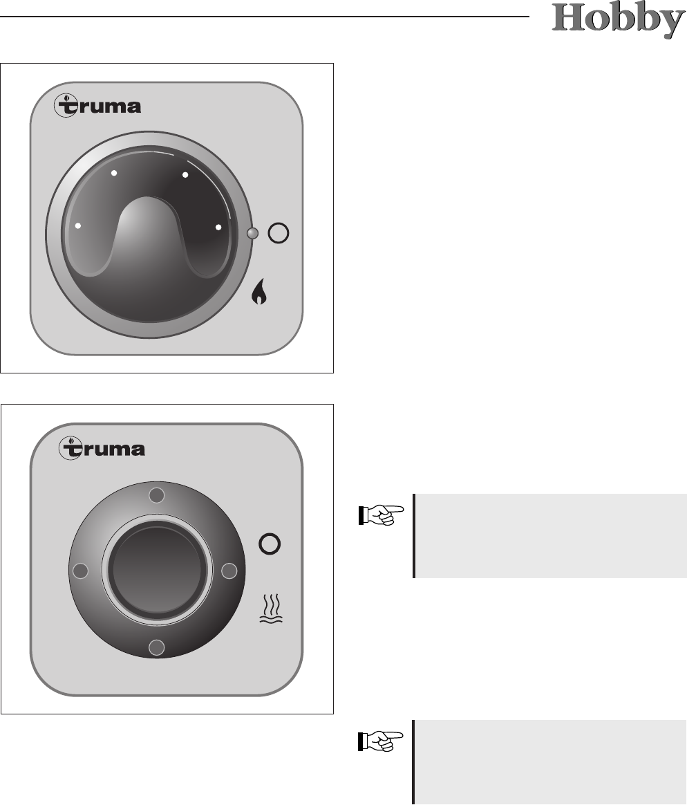
Adjustment by hand
•Turn the rotating ring
l
to "M".
•Adjust the desired level via the turning knob
m
.
To turn off
•Turn the rotating ring
l
to "O".
Automatic operation
•
Turn the rotating ring
l
to "A".
3
The electronic system regulates the required
blower speed and limits the RPM to the value set
on the adjusting knob
k
.
Booster Stage
•Turn the rotating ring
l
to " ".
•Set the blower speed on the adjusting knob
k
to "5" (for maximum air ow volume).
The thermostat sensor is located at
the bottom of the heater. Please note
that a cold draft will adversely affect
the thermostat. Such sources of in-
terference must be eliminated; other-
wise, there is no guarantee that you
will be able to adjust the temperature
to your satisfaction.
Room Thermostat
- For an average room temperature of approx.
22° C without using the fan, set the thermostat
k
to about "3". To feel comfortable and distri-
bute the warm air evenly, Truma recommends
that you use the fan and set the thermostat
k
to about "4".
- The exact thermostat setting must be deter-
mined in accordance with the oor plan and
your personal comfort.
2
10-5
10.3 Electric auxiliary heating*
The electric auxiliary heating (Ultrahe-
at) operates only when the caravan is
connected to the 230V mains supply.
The electric auxiliary heating is integrated in the
hot-air heating system. This allows for three pos-
sible heating methods:
- just the gas heater
- gas heater + electric heater
- just the electric heater
The electric auxiliary heating allows you to heat
up the vehicle more quickly. It has three power
settings:
- 500 W
- 1000 W
- 2000 W
Before switching on the Ultraheat,
please ensure that the fuse protection
of the electrical supply at the caravan
corresponds to the power setting you
have selected.
During operation, the reecting panel
of the heater will get very hot in some
places.
The power feed lead for the caravan
must be completely unwound from the
cable drum.
If you operate on electricity and gas at
the same time to heat, the electric com-
ponent will switch itself off to prevent the
stronger gas burner from possibly over-
heating.
10-6
10.4 Electrical oor heating*
The heating system is located in the middle
walking space of the oor. It is 60 cm wide; the
length depends on the type of vehicle. This he-
ating system is not meant to heat the room; in-
stead, it reduces the loss of heat via the oor.
To turn on the 24 V oor heating
You will nd the switch on the service panel. The
oor heating operates only when the caravan has
been attached to a 230 V power supply.
Technical data
Voltage 24V~ from its own 230V/24V transfor-
mer.
Depending on the length of the caravan, power
consumption lies between 150W and 320W.
To prevent local hot spots, do not
place objects for a longer period of
time on the oor if the oor heating
system has been turned on. Do not
drill any holes in the oor or screw in
any screws.
To switch on
• Set the rotary switch to the desired power set-
ting (green indicator light will light up during
„Operation“).
• Set the desired room temperature using the
rotary switch.
To switch off
• Use the rotary switch to turn off the heater.
To distribute hot air evenly and
quickly and ensure that the surface
temperature on the heater is reduced,
the heater should be operated only
when the circulation fan has been
switched on.
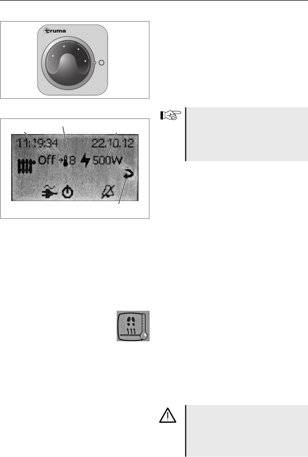
Ultraheat
230 V ~
2000
500
1000
1
3
5
7
9
Ultraheat
On/Off
Room temperature
Power setting
500 - 1000 - 2000 W
Return
Quit the menu
Standard rotary switch
Menu for LCD panel
10-7
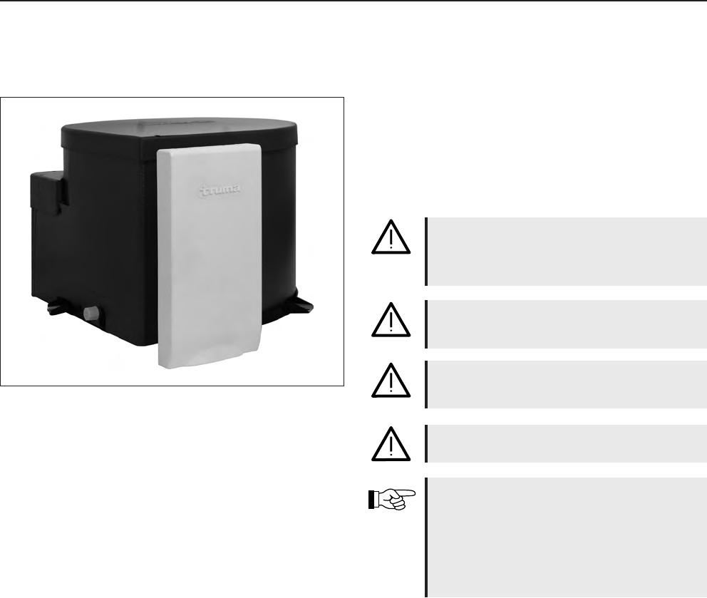
10.5 Hot-water heating system*
You are not permitted to operate the
hot water heater while driving.
The Compact 3010 LPG heater is a hot-water
heating system which heats hot water separately
(contents: 8.5 l). It is possible to heat up the he-
ating system without lling the hot-water heater
with fresh water.
Location
• In the wardrobe.
Important information
• Please read the separate operating instructions
carefully before initial operation of the heating
system.
• Always turn off the main switch for the heating
system whenever the vehicle is not in use.
• If there is danger of frost, always drain off the
fresh water in the hot-water heater.
• You may not start the heating if the device has
not been lled with glycol.
• To make the best possible use of the convection
principle, the air must not be prevented from
circulating throughout the caravan, e.g. behind
the back cushions, winter ventilation slots, in the
bed frame and behind the stowage cupboards.
Modes of operation
• LPG operation
• Heating cartridge operation (230 V)
• Combined LPG and heating cartridge operation
Function modes
• Water heating
• Heating and water heating
• Heating
Check the amount of liquid in the ex-
pansion tank at regular intervals. When
the heating is off, the liquid should be
approx. 1 cm above the "Min" mark.
10-8
For further detailed information on
operation, handling and maintaining
the hot-water heating system, please
refer to the separate operating in-
structions for “Alde Compact 3010”.
Operating device
When in the idle position, the device shows
which heating functions have been activated; the
background lighting of the display is off.
After two minutes, the operating device automa-
tically switches from the set position to the idle
position if no button has been pressed or if the
idle position has been set using the arrows.
To start the hot water heater
Press the On/Off button. The heater will start,
using the settings that were last selected. The
Alde logo appears on the display.
Idle state
A Clock
B Outside temperature
C Inside temperature
D Circulation pump
E Remote indicator
F 230V connection
G Menu button
H On/Off button
Settings menu
Press the menu button to reach the Settings
menu. Any settings you make will be automati-
cally saved after 10 seconds. If no buttons are
pressed, the control unit will return to the idle
state after 2 minutes.
If the vehicle is equipped with an
LCD control panel, the basic func-
tions of the hot water heating system
can be controlled using the panel
next to the entrance (see p. 07-11).
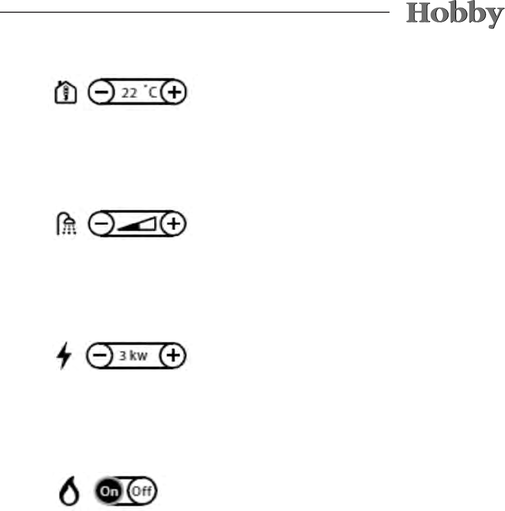
10-9
Setting the desired temperature
(+5°C to +30°C)
by pressing – or + in steps of 0.5°C.
Hot water (50°C) is always available when this is
switched on. The hot-water system is operated
electrically or uses LPG.
Setting the hot water
Should you require more hot water, the tempera-
ture can be increased temporarily from 50°C to
65°C. After 30 minutes, the hot-water heater will
switch back to normal operation. Increase the
amount by pressing +; turn the hot water off by
pressing -.
Setting the electric heating system
Use the – and + buttons to select the output
(Off, 1/2/3 kW). Preference is given to electrical
operation when selecting whether to operate on
electricity or gas.
Setting for heating with gas
Set the heating to gas operation. Start operation
with gas by pressing the On button. The heating
system will operate until the temperature you
have set has been reached. Turn gas operation
off by pressing the Off button.
10-10
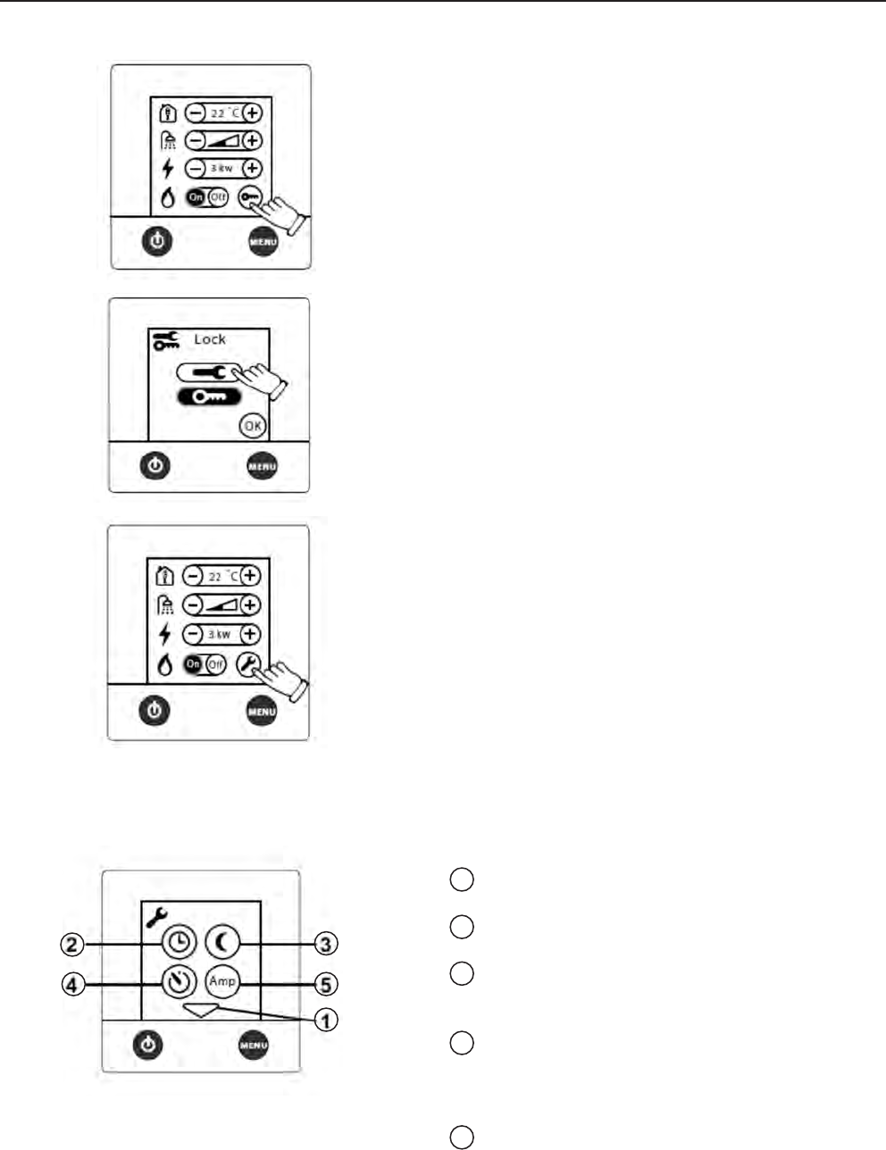
Activating the Tools menu
The Tools menu is used to control the remaining
functions of the control unit.
To activate the Tools menu, the following icons
must be pressed, as shown on the left:
Functions of the Tools menu
1Arrow icons enabling you to switch between
the individual Tools elds.
2Setting the clock to use functions such as
automatic start or automatic temperature.
3Automatic temperature change to set
temperatures, e.g. at night or on individual
days.
4Automatic start at a later time. The heating
system will run for 24 hours and repeats this
procedure every week at the same time.
The On/Off button must be set to Off.
5Overload protection prevents 230V fuses
from overloading. If power consumption
exceeds the value that has been set, the
electric output of the heating system will
automatically be reduced.
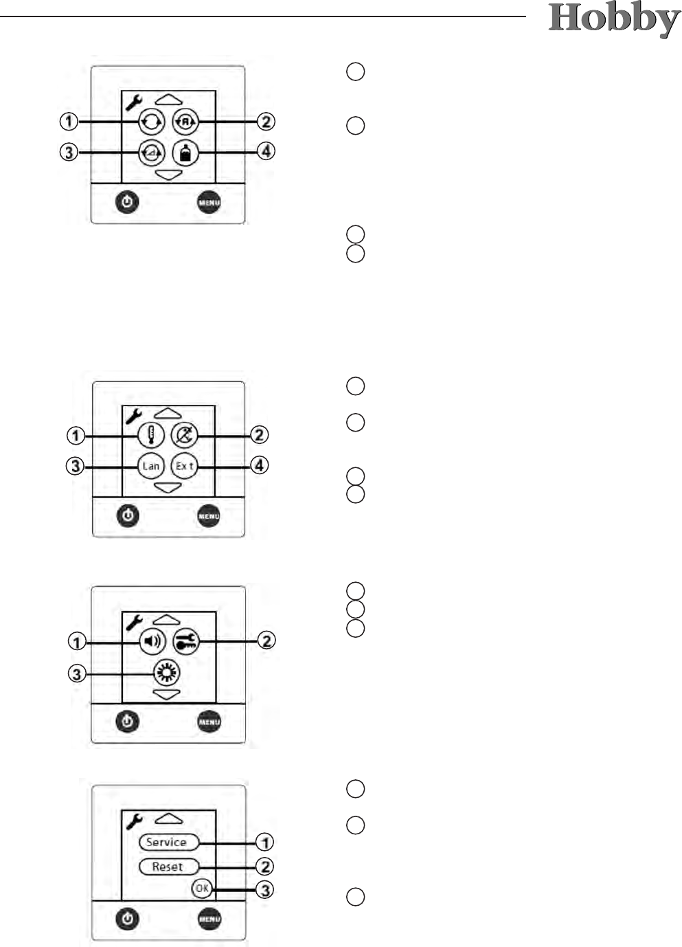
10-11
1Continuous operation of the pumps to limit
the volume of hot water, especially if little
heating is required.
2
Pump Auto / 12V – the 230V pump will run
if this is set to the auto position; if the 230V
electric power supply is interrupted, the 12V
pump will start up. If set to 12V, the 12V
pump will run even if the 230V electric power
supply has been connected.
3
Setting the pump speed.
4This function is used in combination with
the automatic gas-bottle change-over (Duo-
Comfort). It indicates whether the liquid gas
bottle is empty..
1
Temperature setting for calibrating the tem-
perature using the control unit.
2Automatic increase in temperature at 2.00
a.m. to reduce danger of Legionella
bacteria.
3Language setting (German, English, French)
4Function for external start, e.g. using GSM.
1Setting for key tone.
2Lock/Activate access to Tools menu.
3Setting the light intensity from 1-10.
1The Service function allows you to view cer-
tain values on the display (only in English).
2Resets the system to the manufacturer's
default settings (heating Off; electrical
operation 1kW; heating with LPG On; inside
temperature 22°C).
3Quits the Tools menu
10-12
Error messages
Error messages are shown on the display
(panel in idle state).
Battery low: if voltage sinks to under 10.5V,
the heating system will switch
off. Automatic reset to above
11V.
Fan failure: incorrect fan speed. Automatic
reset after 5 minutes.
Gas failure: gas bottle is empty. Reset by
switching off or restart.
Overheating is red: to reset, interrupt the 12V
electric power supply and
connect it again.
Overheating is blue: to reset, interrupt the 12V
electric power supply and
connect it again.
Window is open: the heating system interrupts
the gas supply when the
window is open. Shut the
window.
Connection failure: connection error between the
heating system and the panel.
Switch the main voltage off
and then on again.
Panel failure 1: panel error
Panel failure 2: panel error
10-13
Refrigerators made by Dometic will be installed.
If the external temperature is high, full refrige-
rating capacity can only be ensured by means
of sufcient ventilation. If necessary, to achieve
better ventilation, the refrigerator’s ventilation
grille can be removed at the caravan.
Methods of operation
The refrigerator can be operated in three ways.
The desired mode of operation is set using the
energy selection switch.
-12 V operation: electrical supply from the bat-
tery of the base vehicle (ignition lock on),
-230 V operation: electrical supply from an
external source,
-liquid gas: gas bottles from the caravan.
12 V operation
•Set the energy selection switch to the battery
symbol.
• 12 V operation will only work when the motor
of the base vehicle is running.
• The refrigerator operates without regulating
the thermostat (continuous operation). The-
refore, 12 V operation should only serve to
maintain the temperature that has already
been reached.
• To switch off, turn the energy selection switch
to 0.
230 V operation
• Set the energy selection switch to mains ope-
ration.
• Use the thermostat to regulate the tempera-
ture.
• To switch off, turn the energy selection switch
to 0.
Gas operation
• Set the energy selection switch to gas opera-
tion.
• Open the main shutoff valve on the gas bottle
and the gas shutoff spigot marked “refrigerator”.
10.6 Refrigerator
Turn on the refrigerator at least 12
hours before putting anything in it and,
if possible, store only goods that have
already been cooled.
10-14
• Turn the thermostat up full and keep it pressed
down. The refrigerator will either ignite automa-
tically or by using the knob for manual ignition
(depending on your model).
• When it is ignited, let go of the thermostat. Re-
peat the previous step if it has not ignited.
• Use the thermostat to regulate the cooling efci-
ency.
•
To switch off, turn the energy selection switch to 0.
• Close the main shutoff valve on the gas bottle
and the gas shutoff spigot marked “refrigerator”.
The refrigerator door must always be
kept shut and locked while driving.
Lock on the Slim Tower model
There is an automatic lock on the door of the
'Slim Tower'.
If you close the refrigerator and press the door
rmly shut, it will lock automatically.
Lock on the Dometic model
Lock on the refrigerator door
It is not permitted to operate the refrige-
rator with gas
- at petrol stations
- while driving
- when transporting the caravan by means
of a transport or towing vehicle.
This may cause a re.
10-15
• Food should always be stored in closed con
tainers, aluminium foil or similar materials.
• Never store heated food in the refrigerator;
always let it cool off rst.
• Goods that might emit readily volatile or am
mable gases must not be stored in the refri
gerator.
• Always store perishable food directly next to
the cooling ns or as close to the bottom of
the refrigerator as possible.
Storing food
The freezer compartment is suitable for making
ice cubes or for storing frozen food for a short
period of time. It is not suitable for freezing food.
It is not suitable for freezing food nor
for the proper storage of medication.
Removable freezer (Slim Tower)
To make the best use of space, the freezer can
be removed.
To remove the freezer
• Fold down the locking clamps underneath the
freezer.
• Push both clamps towards the middle.
• Pull the freezer slightly out.
• Unhinge the door.
• Remove the oor panel of the freezer.
Turn on the refrigerator at least 12
hours before putting anything in it.
10-16
10.7 Gas cooker
The kitchen segment of the caravan is equipped
with a 3-ame gas cooker.
Before rst use:
• Open the bottle valve and the quick-close
valve in the gas line.
•The roof ventilation or the window must be
open while operating the gas cooker.
•Operation handles, which must be pressed to
ignite gas devices, must automatically spring
back into the original position upon release.
•Before you use the gas cooker for the rst
time, any ame guards that may be provided
must be set up or permanently fastened so
as to provide effective heat protection for
components and furnishings that may be
endangered by re.
• The sockets above the cooker may not be
used when cooking. Shut the protective caps.
Cookers or other devices which use
combustion air from the interior may
never be used to heat the vehicle;
this would cause a potentially life-
threatening lack of oxygen due to
carbon-monoxide build-up.
The cooker may not be used when
the glass covering is still on it.
10-17
Operation
• Open the cover
j
.
• Set the turning knob
k
of the desired burner
in the ignition position (large ame) and press.
• Ignite the burner with gas lighter uid, a
match and/or lighter.
• Hold the turning knob
k
in for an additional
10-15 seconds.
• Release the turning knob
k
and position it to
the desired setting (large or small ame).
• If the ignition is unsuccessful, repeat the pro-
cess from the beginning.
Use potholders or mitts when hand-
ling hot pots, pans and similar ob-
jects. Danger of injury!
Keep the cover
j
open after coo-
king for as long as the burners are
still giving off heat.
Do not store easily inammable
objects such as dish towels, napkins,
etc., near the cooker. use the protec-
tive device on the cooker at all times
when cooking. Danger of re!
Never allow gas to escape without
burning. Danger of explosion!
2
1
10-18
10.9 Oven*
• The ventilation openings on the
oven must never be closed.
• Only operate the oven when it has
been connected to the 230 V mains
(automatic ignition).
• A skylight or window must be ope-
ned when operating the oven.
• The oven door must remain open
while igniting the oven.
• If it has not ignited, repeat this pro-
cedure from step 1.
• Should the ame on the burner ac-
cidentally be extinguished, turn the
switch back to the neutral position
and leave the burner off for at least
one minute before igniting it again.
10.8 Fume hood*
As an option, the kitchen can be tted with an
extractor fan. The built-in fan blows kitchen
odours directly outside.
Clean the lter of the fume hood regu-
larly, as it collects the fat from kitchen
odours.
The kitchen light, which is operated via the con-
trol panel, can also be switched on using the left
button.
Press the right button to turn on the fume hood.
Hold the fan button rmly to select the speed of
the fan from among 15 different speeds.
10-19
Turning on the oven
• Switch on the 12 V power supply using the
main switch on the control panel.
• Open the main shutoff valve on the gas bottle
and the gas shutoff spigot marked “oven”.
• Open the oven door completely.
• Position the baking tray or grill so that it is not
in direct contact with the ame.
• Press the switch lightly and set it to the
desired ignition position (oven or grill, if availa-
ble).
• Press the switch. Gas ows to the burner and
the ame will ignite automatically.
• Press the switch for several seconds until the
safety pilot valve keeps the gas ow open.
• Let go of the switch and turn it to the desired
setting (oven only).
• Close the oven door carefully to prevent the
ame from extinguishing.
Turning off the oven
• Turn the switch to the neutral position. The
ame will extinguish.
• Close the main shutoff valve on the gas bottle
and the gas shutoff spigot marked “oven”.
• Never operate the oven when it is
empty (i.e., without food that is to
be heated).
• The grill * should never be used
for longer than 25 minutes and only
operated when the oven door is
open.
• Never use the oven to heat the
caravan.
10-20
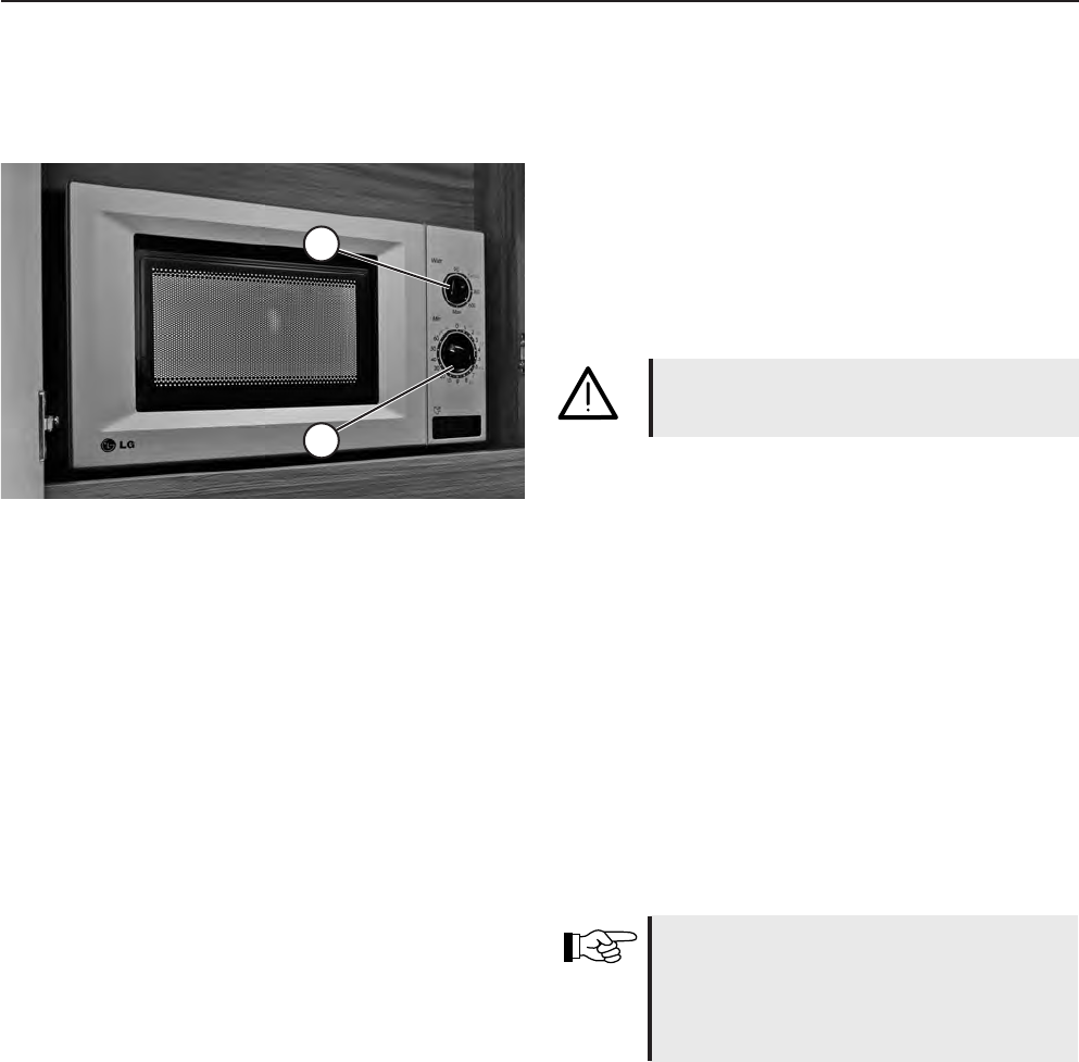
10.10 Microwave*
The kitchen of your camper can be outtted with a
230 V microwave, which is installed behind a ap
in the kitchen wall cabinet. This device is suitable
for defrosting, heating up and cooking food for
your personal use.
Leave the ap open when operating
the microwave. Risk of overheating!
To operate
• Turn the upper knob to the desired level of
power
j
.
• Select the desired cooking time by turning the
lower knob, taking the recommendations into
account
k
.
• The microwave will automatically start to heat
up once the time and level of power have
been entered.
• The device will make a beeping signal when
the time has expired.
• When not in use, please set the time (2) to"0".
Please refer to the separate operating
instructions for safety instructions and
detailed information on how to ope-
rate, use and care for the microwave.
1
2
11-1
11. Accessories
Note the detailed operation instructions, instal-
lation instructions and circuit diagrams from the
manufacturers when using accessories. These
are located in your service package.
•Any changes to the status of the caravan as
delivered by the manufacturer may endanger
driving performance and roadworthiness.
•Anyaccessories,add-ons,modicationsor
mounted parts that have not been approved
by HOBBY may cause damage to the vehicle
and impair its roadworthiness. Even if an
expertise, general type approval or design
approval has been provided for these parts,
this does not ensure the orderly condition of
the product.
•HOBBY cannot accept liability for any
damages caused by parts or changes that
have not been approved by HOBBY.
The following table includes a list of weights for accessories. If these parts are carried in or on the
caravan and are not included in the standard scope of delivery, they must be taken into consideration
when determining the full load.
Object Weight [kg]Object Weight [kg]
50 l instead of 25 l built-in fresh water tank 28.0
7-zone cold foam mattress 2.9
Adapter 7/13-pole 0.3
Additionalserviceap0.5
Air-conditioning Dometic HB 2500 25.0
Alde hot-water heater Compact 3010 27.5
AL-KO spare tyre holder + spare tyre 28.2
AL-KO spare tire holder 7.7
Antenna mast, Teleco 0.9
Bed expansion for single beds 5.0
Bedspread 1.5
Bicycle carrier rear/drawbar 6.8/9.2
Boiler 15.0
Bunk bed, 3-storey 15.0
Car jack with box 6.0
Charge controller incl. 600 VA
electrical supply 2.8
City water supply 0.5
Clothes rod in shower 0.3
Dinette instead of centre seating arrangement 0.0
Dometic fume hood 3.0
Double bed instead of long bed
with children's bunk bed (UKF) 15.0
Drawbar anti-theft device Robstop 3.0
Extendable shelf/articulated mount
for LCD television 2-3
External socket in outer tent 0.4
Floor heating 4.0 - 6.0
Front landing wheel with load indicator 0.6
Front window/pane 11.3
Garage 5.0
Gas, external socket 1.5
Heavy-duty stanchions 1.6
Increased load, single axle 0 - 24.0
Increased load, tandem axle 16.0
LCD control panel 0.0
Leather interior 10.0
Microwave 12.0
Oven incl. light, grill and electric ignition 15.0
Pillared table 0.5
Queen-size bed, crossways in the rear 8.0
Remote control for lighting system 0.3
Removable carpeting
for de Luxe models 7.0 - 10.0
Removable carpeting
for De Luxe/easy models up to 7.0
Roof awning 23.0 - 49.0
Self-sufcientpackage29.0
Shower device in external washroom 2.8
Sound system 11.0
Spare tire incl. mount for bottle container 22.2
Truma electric auxiliary heating Ultraheat 2.0
Truma heating S5004 instead of S3004 8.0
Truma hot-air system Isotherm 3.0
Universal mount for LCD television 3.5
11-2
12-1
12. Maintenance and upkeep
12.1 Maintenance
Maintenance intervals
xed maintenance intervals apply to the caravan
and the devices installed in it.
Rules for maintenance intervals
• Have the rst maintenance performed by a
HOBBY dealer 12 months after the initial
registration.
• Havve all further maintenance performed
once annually at a HOBBY dealer.
• Have all maintenance on built-in devices
performed in accordance with the corres
ponding maintenance intervals indicated in
the operating instructions.
1
Greasing and oiling
Regularly examine and grease the sliding parts
and stationary parts of the chassis. If the ca-
ravan is used seldom, yearly maintenance is
required.
Rules for greasing and oiling
•Grease the bearings on the rocker arm
j
on
the axle shaft every 5,000 kilometres travelled
or at least once a year.
•Movable parts such as pins and hinged parts
on the hand brake lever and deexion lever of
the ramp should be oiled lightly.
HOBBY grants a 5-year guarantee on
the absence of leaks in the caravan in
accordance with the guarantee condi-
tions.
To this end, the vehicle must be taken to
your HOBBY dealer every 12 months for
a chargeable inspection for leak tight-
ness.
The inspection of the gas facilities
(subject to extra cost) is to be repea-
ted every two years by a liquid gas
expert. This inspection is to be con-
ducted and certied in accordance
with the German Association of Gas
and Water Experts, worksheet G 607,
and EN 1949. The operator is respon-
sible for scheduling this inspection.
Replace safety regulator knobs and
hoses after 10 years at the latest!
12-2
For safety reasons, the spare parts for
heating devices must conform with
the manufacturer's instructions. They
must be installed by the manufacturer
or an authorised representative.
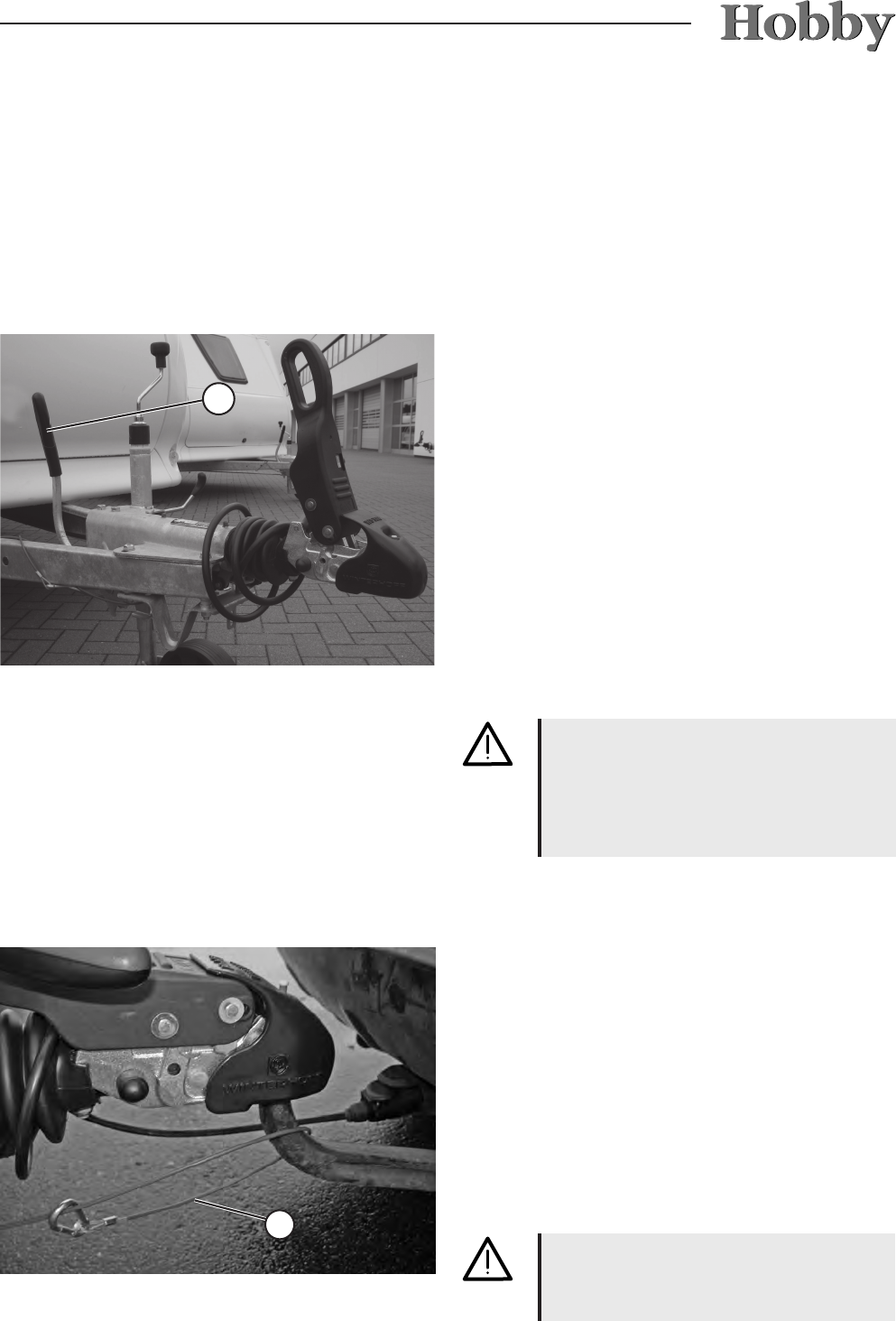
Coupling ball on base vehicle
Ensure that the coupling ball meets the required
dimensions and is undamaged, clean and free of
grease. When using dacromet-coated (dull silver
anti-corrosion coating) as well as lacquered cou-
pling balls, the coating must be removed com-
pletely with sandpaper (200-240 grain) so that
it does not create deposits on the friction lining.
The metal surface of the coupling ball must be
bright. A damaged or dirty coupling ball causes
increased wear and tear on the friction pads; a
greased coupling ball negates the stabilizing ef-
fect. Thinning solvents or spirit are both suitable
for cleaning.
12.2 Drawgear
The axle(s) of the caravan is (are)
tted with compact wheel bearings.
The cylinder hub, compact bearings
and axle nuts form a closed unit.
The compact bearings are free of
maintenance due to their special
grease.
The wheel brake may never be
repositioned on the xing lock or on
the yoke end of the bars!
Only reposition the wheel brake on
the self-securing stationary hexago-
nal nut!
You can nd further guidelines in
the operating instructions from the
axle supplier.
2
• Lightly grease the stationary parts on the case
of the overrunning equipment
k
after every
5,000 kilometres of driving.
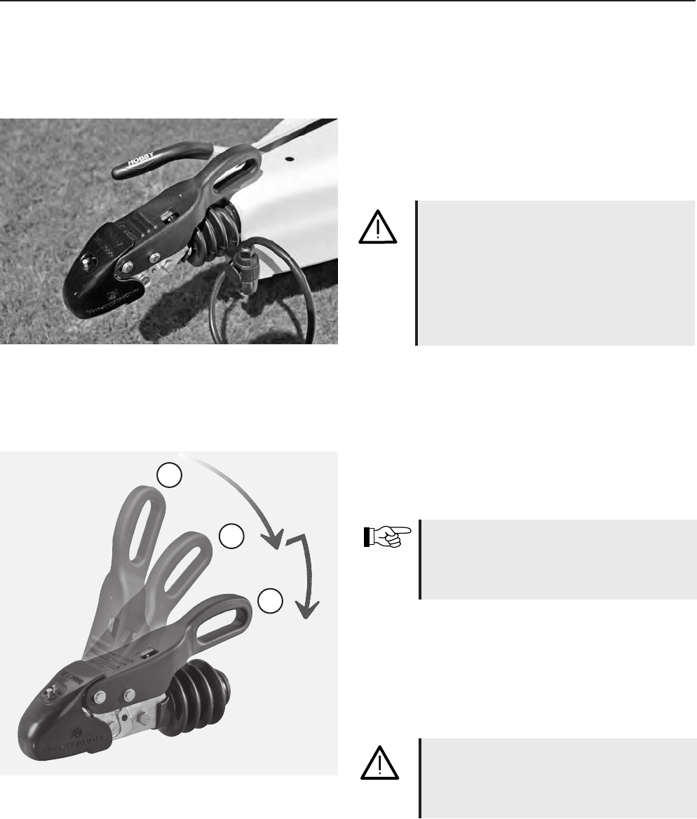
IMPORTANT: The friction elements of the
WS 3000 safety hitch may NEVER be oiled
or greased.
•Check from time to time to ensure that the bea-
ring surfaces of the thrust rod are not jammed.
•Clean and oil all movable and stationary parts
regularly.
12-3
Changing the friction lining
It is very easy to exchange the friction pads
j
when they are worn out. Messrs. Winterhoff
offer a corresponding set of spare parts. Please
note the detailed instructions for assembly in the
manufacturer's spare part kit.
Noises
Certain noises can occur during the course
of the drive; these noises, however, have no
inuence on the operative effectiveness of the
tension ball coupler.
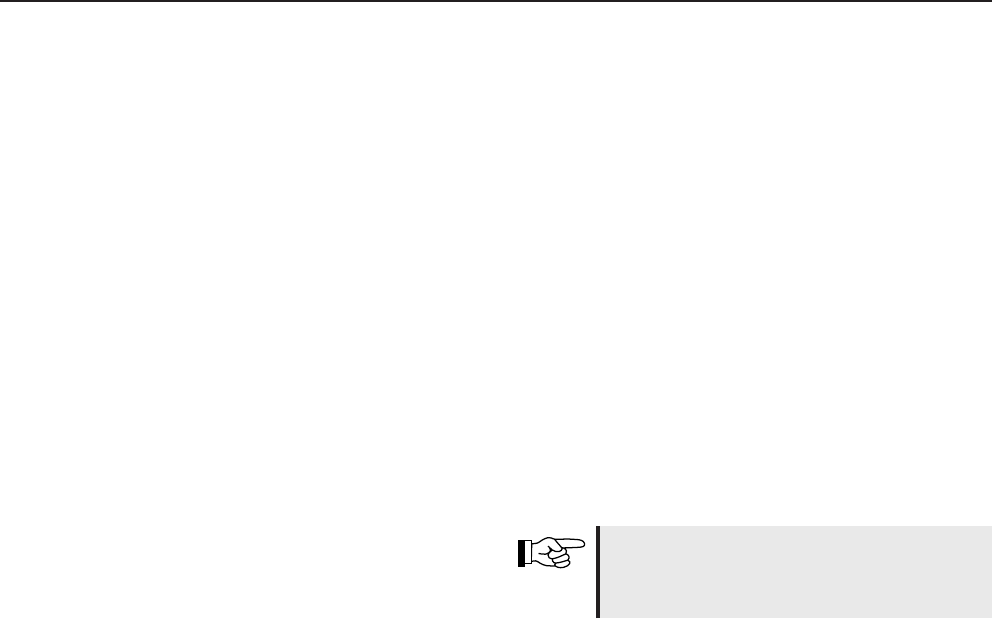
Possible causes of these noises can be:
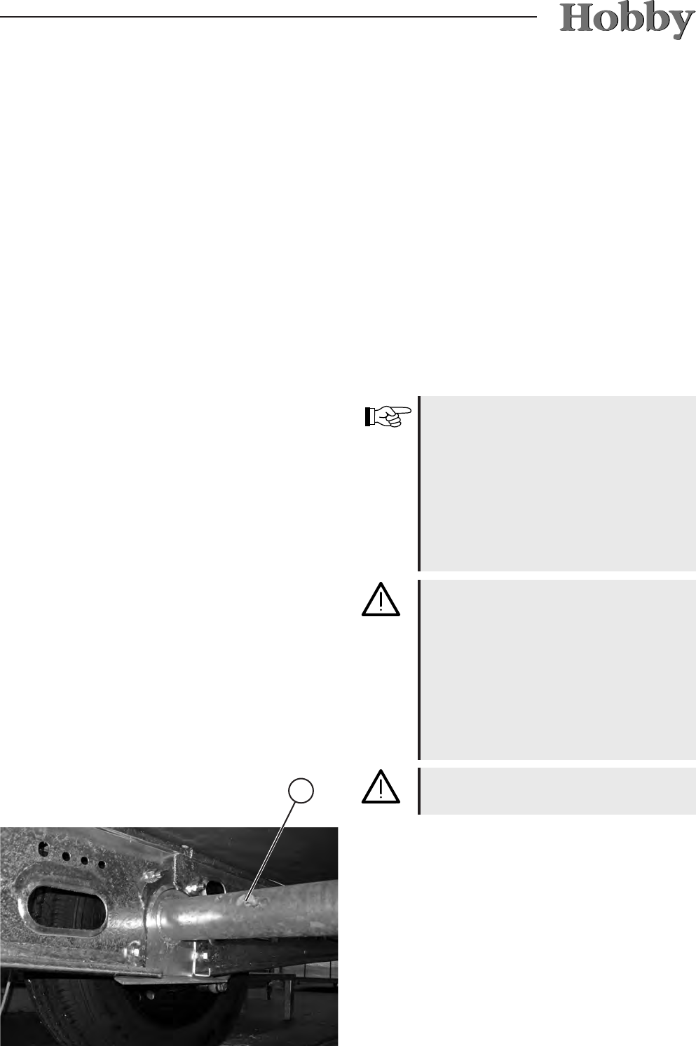
1
. a dacromet-coated coupling ball on the
base vehicle.
2. A galvanized or varnished coupling ball on the
base vehicle.
3.A damaged, rusty or dirty coupling ball on the
base vehicle.
4.dirty friction elements
j
on the tension ball
coupler.
5. the towbar or tie rod in the linings of the over-
running equipment are running dry.
Hints
For 1., 2. and 3.:
Sand down the surfaces of the coupling ball and
clean them with a thinning solvent or spirit.
for 4:
Clean the surface of the friction elements with
sandpaper (200-240 grain) and then clean with
petroleum ether or spirit.
for 5:
Use a lubricating nipple to grease the linings.
Pull back the shock absorber and grease the
bare towbar.
1
1
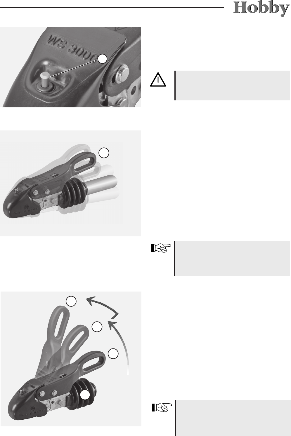
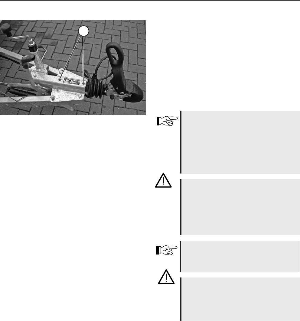
Tension ball coupler
Keep the friction linings inside the tension ball
coupler clean and free of grease (Fig. 5). When
the friction linings are dirty, the surface can be
cleaned with 200-240 grain sandpaper. Then
clean with petroleum ether or spirit. All movable
bearings and bolts are easy to grease. By regular
upkeep and maintenance of your WS 3000, you
increase its overall life span, function and safety.
12-4
12.3 Brakes
Initial inspection
The wheel brakes that have been installed are
drum brakes that do not adjust automatically.
(Exception: Premium)
To ensure trouble-free brake performance, the
wheel brakes must be adjusted regularly.
The brakes must rst be inspected after you
have driven 500 km. Have them inspected again
after every 10,000 km of driving, but at least
once every year. Inspections must be documen-
ted in the KNOTT service manual by the autho-
rised specialist who carries out the inspection.
These documented reports are just as much a
prerequisite for any possible guarantee claims as
is the compliance with the regulations for main-
tenance and upkeep.
12-5
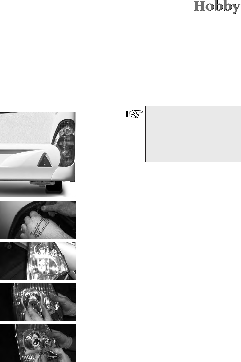
12.4 Changing the taillight bulbs
• Carefully remove the protective caps with a
screwdriver.
• Now you can remove the taillight from the
frame.
• Remove the holder by loosening the screw.
• The bulbs are now freely accessible.
Put the taillight back together by repeating the
process in reverse.
• Remove the four fastening screws with a
crosstip screwdriver.
The following description for changing the rear
light bulbs refers to the De Luxe easy model.
Different rear lights are used in the Premium
and Landhaus models. Unfortunately, it is not
possible to replace these light bulbs easily. In
this case, please speak to your dealer, who will
be pleased to assist you in changing these light
bulbs.
Some of the rear lights in the Premi-
um models are tted with LED lights,
whereby each individual light has a
standardised alignment. Therefore,
due to the authorisation required, indi-
vidual LED lights may not be changed.
Should they be defect, the entire rear
light must be replaced.
12-6
The following description for changing the rear
light bulbs refers to the De Luxe, Excellent and
Prestige models.
• Remove the two screws
j
.
• Remove the rear light from the lighting beam.
• Remove the bulb from the socket by turning it.
Carry out this procedure in reverse order to
install a new bulb and replace the rear light.
1
12-7
12.5 Ventilation
12.6 Upkeep
Sufcient ventilation and de-aeration of the vehi-
cle interior is essential to maintaining a com-
fortable climate. In addition, corrosion damage
from sweat residue can be avoided.
Sweat residue forms most readily
- in tight spaces,
- from the breath and perspiration of the passen
gers,
- by carrying in damp clothing,
- when operating the gas cooker.
Ensure sufcient air circulation to pre-
vent damage from the collection
of sweat residue!
Cleaning the exterior
The vehicle should not be washed more often
than necessary.
Only wash the vehicle at specially
designed wash sites.
Use cleaning solvents as sparingly
as possible. Aggressive cleaners such
as rim cleaner pollute our
environment.
Do not use cleaners which contain
solvents.
Rules for cleaning the exterior
• Rinse the vehicle with a light stream of water.
• Wipe the vehicle down with a soft sponge and
typical shampoo solution.
Rinse the sponge often in the process.
• Afterwards, rinse with a great deal of water.
• Dry the vehicle with a suede cloth.
• Allow the vehicle to stand out in the open
after washing to let it dry.
12-8
Cleaning with a high-pressure cleaner
Note the instructions for the high-pressure
cleaner before washing the caravan with it. Keep
a minimum distance of 700 mm between the
caravan and the high-pressure nozzle.
Note that the water jet comes out of the cleaning
nozzle with a great deal of pressure. Incorrect
use of the high-pressure cleaner can damage the
caravan. The temperature of the water must not
exceed 60° C.
Keep the water jet constantly moving during the
entire washing process. The water jet must not
be aimed directly at the clearance between the
door frame and door leaf or the window frame
and window leaf, electrical add-ons, pin-and-so-
cket connectors, gaskets, sealing grill for refri-
gerator or the roof lights. This can damage the
vehicle or allow water to seep into the interior.
Thoroughly dry the light sockets,
because water collects there easily.
Labels and exterior decorations
should not be sprayed directly with a
high-pressure cleaner, because they
may come off.
Never use caustic cleaners or clea-
ners which contain solvents.
Cleaning products not recommended for use:
• abrasive cleaning agents (scratch the surface)
• cleaning agents that contain acetone (immediately
damage the plastic)
• dry cleaning products
• diluents
• alcohols
• solvent-based cleaners
• cleaners from the chemical group such as ketone,
ester and aromatic solvents
• aromatic hydrocarbons (e.g. all automotive fuels)
Direct contact with plastics such as PVC, soft PVC
and similar products (e.g. stickers) must be avoided
at all cost.
12-9
Do not polish too often since polishing
removes the top layer of paint. Fre-
quent polishing causes more damage
than it remedies.
Rules for treating tar and resin stains
• Remove residues from tar and resin as well as
other organic stains with petroleum ether or
spirit.
Do not use aggressive solvents such as
products containing esters or ketone.
Rules for damage repair
• All damage should be repaired immediately
to avoid further damage from corrosion. Con
sult your HOBBY dealer.
Rules for waxing the surfaces
• Treat the paint surfaces periodically with wax.
Note the guidelines for use from the wax
manufacturer.
Rules for polishing surfaces
• In exceptional cases, treat damaged paint sur
faces with polish. We recommend paste pol-
ishes free of solvents.
It is not possible to avoid transmitting plasticizers
when solvent-based contents come into contact
with the aforementioned plastics and this causes
the parts to become brittle.
12-10
Talcum is available in auto specialty
stores.
Do not use strong and aggressive
cleaners which contain softeners or
solvents!
Windows and doors
Window panes requires particularly careful treat-
ment.
Rules for upkeep
• Rub the insulation of doors and windows
lightly with talcum.
• Only clean acrylic glass window panes with a
clean, moist sponge and a soft towel. Dry
cleaning can scratch the panes.
Should salt adhere to the hot-dip galvanised
chassis, it will damage it and may cause white
rust. However, white rust is not a defect, but
merely an optical impairment. After driving in
winter or through salty water, the hot-dip galva-
nised surfaces should be rinsed with clear water.
The combustion air intake duct for the
heating system is located underneath
the oor of the vehicle. Under no cir-
cumstances may liquid sprays, under-
body protection or similar products be
allowed to interfere with it.
Chassis
The chassis of the caravan has been specially
coated. If the protective coating is damaged,
repair it immediately. Coated areas should not be
treated with spray oil.
12-11
We recommend the following methods for
cleaning:
Method A:
• Use only commercial cleaning agents that
have a water basis.
• Alternatively, add two tablespoons of ammo-
nia to 1 litre. Dip a cloth into this solution and
gently sponge the spot. Turn the cloth over so
that you are using a clean cloth to touch the
spot.
This method is particularly suitable for removing:
- wine, milk, lemonade
- blood
- biro, ink
- urine, sweat
- mud
- vomit
Cleaning instructions for mate-
rials that contain Teon
• Always treat spots immediately.
• Sponge spots, but do not rub them.
• Work from the edge towards the
middle of the spot.
• Never use household cleaners to
remove spots.
• Hoover cushions regularly to remove
any dirt that may have collected.
Cleaning the interior
Rules for cleaning seat covers, upholstery
covers and curtains
• Clean seat covers with a soft brush or vacu-
um cleaner.
• Have heavily soiled upholstery covers, bed-
spreads and curtains dry cleaned; do not
wash them yourself!
• Clean with the foam of a gentle detergent if
required.
To reduce problems arising from
dampness, use water sparingly when
cleaning inside.
12-12
Do not use scouring solvents or inten-
sive cleaners since these can scratch
the surface!
• Rub dry with a soft, dust-free cloth.
• Use mild furniture polish.
Rules for furniture surfaces
• Clean wooden furniture nishes with a moist
cloth or sponge.
• Clean the surface with a special solvent for
PVC surfaces. Do not place carpets on wet
PVC surfaces. Carpets and PVC surfaces
could stick together.
• Never use chemical cleaners or steel wool,
because they will damage the PVC surface.
Rules for cleaning the carpet
• Clean with a vacuum cleaner or brush.
• If necessary, treat or shampoo with carpet
foam.
Rules for cleaning PVC surfaces
Method B:
• Use only mild, water-free solvents for dry
cleaning.
• Dampen the cloth and proceed as described
in method A.
This method is particularly suitable for removing:
- wax, candles
- pencil
Chocolate or coffee should only be washed out
with luke-warm water.
Sand and dust can damage the sur-
face of a PVC surface that is walked
on regularly. When in use, clean the
oor daily with a Hoover or broom.
12-13
• The space behind the refrigerator should be
hoovered and cleaned regularly. The ventilation
grille should also be kept clean. The door seal
should be rubbed once a year with talcum po-
wer to keep it supple and the expandable fold
should be checked for tears.
• The lter in the fume hood must be cleaned
occasionally, because cooking fat collects
there. We recommend that you use warm
water with a bit of dishwashing liquid to clean it.
The following applies for built-in equipment:
• Heating: remove all of the dust that has coll-
ected on the heat exchanger, base plate and
fan wheel of the hot-air system at least once a
year before the caravan season begins. Clean
the fan wheel carefully with a brush or small
scrubber.
• The glycol mixture in the hot-water heating
system should be replaced every two years,
because certain properties such as protection
against corrosion deteriorate.
Do not use scouring cleaners in the
toilet area either!
Rules for cleaning the toilet area
• Clean with neutral liquid soap and a non-
scouring cloth.
• Do not use a vinegar concentrate to clean the
toilet and the water system or to decalcify the
water system. Vinegar concentrate can dam-
age gaskets or parts of the system.
• The rubber seals of the toilet should be cleaned
regularly with plain water and a lubricant for
seals (not Vaseline or any other vegetable
fats) should be applied. Applying this regularly
to the washer of the valve and other seals in
the toilet will ensure that they stay exible and
function longer.
Do not pour corrosive cleaners down
the drain. Do not pour boiling water
down the drain. Corrosive cleaners
and boiling water will damage the
drainpipes and siphon traps.
Rules for cleaning the sink
• Only clean the sink with typical household
cleaners or special stainless steel cleaners.
12-14
The following applies for the external structure:
• Wash the caravan thoroughly.
• Check the vehicle for damages to the varnish
and other damages. If necessary, repair these
damages and carry out any other necessary
repairs.
• The exterior should be treated with wax or a
special polish for varnish.
• Use a protective agent to protect the metal
parts of the chassis against rust.
• Check the chassis for damage and, if neces-
sary, repair it.
• Use a special cleaner for cleaning the plexig-
lass windows, because normal window clea-
ner makes the material cracked and brittle.
• Rub an acid-free rubber cleaning agent onto
the seals around windows, doors and service
aps to keep them supple.
• Ensure that no water can get into the venting
on the oor, heating system and refrigerator
venting (mount winter covers).
12.7 Winter Lay Up for the Caravan
For many people, the camping season ends
when the temperature starts to fall. Your caravan
must be properly prepared for its winter lay up.
The following general rules apply:
• Only leave your caravan in a closed space if it
is dry and well-aired. Otherwise, it is better to
leave your caravan in the open.
• Cover the safety coupling. Grease the brake
linkage and winding stanchions.
• Jack up the caravan if possible. Extend the
levelling supports to relieve the burden on
wheels and axles to some extent. If possible,
use axle stands to support the chassis.
• Close all gas bottles and emergency shutoff
valves.
• If you use an auxiliary battery (self-sufcient
package), it should be disconnected; ideally,
remove it and store it safe from frost. Check it
about once a month to see if it is still charged;
if not, charge it.
Remove all spray cans with cleaners
and polishes from the vehicle after
nishing the upkeep! Otherwise,
there is a danger of explosion at
temperatures over 50° C!
12-15
The following applies for the interior ttings:
• Clean the interior of your caravan. Hoover
carpets, cushions and mattresses. If possible,
store them outside the caravan. Otherwise,
place them in such a way inside the vehicle
that they do not come into contact with con-
densation.
• Use soapy water to clean linoleum and
smooth surfaces.
• Empty and clean the refrigerator. Leave the
refrigerator door open.
• After cleaning them, leave stowage spaces,
cupboards, drawers and furniture aps open
to facilitate air circulation.
• Leave vents for forced ventilation open. If the
caravan is kept in a closed space, you can
leave the skylight open.
• Air the caravan thoroughly every four to six
weeks when the weather is dry.
• Set up a dehumidier (such as salt) inside the
caravan and dry the granulate or change it
regularly.
Wash the vehicle only in special
places provided for this purpose.
Use cleaning materials sparingly.
Aggressive cleansers, such as wheel
rim cleaners, damage the environment.
The following applies for tanks and con-
tainers:
• Clean, disinfect, descale and completely em-
pty all water pipes and faucets. Leave faucets
open.
• Clean the fresh water tank and empty it by
unscrewing the overow pipe.
• Clean and empty the waste water tank.
• Clean and empty the toilet ushing tank and
the excrement tank. Clean the toilet valve,
apply a lubricant for seals and leave it open.
• Completely empty the therme/boiler.
• If your caravan is equipped with a hot-water
heater: rinse the water heater thoroughly and
empty all of the water.
12-16
• The caravan uses considerably more gas in
winter than in summer. Two 11 kg bottles of
gas will be used up in just under one week.
• Therefore, should you stay longer in one place,
it is worthwhile to set up an outer tent. It will
help to acclimatise the caravan and keep the
dirt out.
With regard to camping in winter, we
recommend that you optimize your
caravan to meet your personal requi-
rements. Your Hobby dealer will be
pleased to advise you.
12.8 Winter Operation
Your caravan has been designed to allow you to
use it in winter.
The following applies for heating:
• Both the air intake as well as the exhaust gas
openings of the heating system must be kept
free of snow and ice (if necessary, use ue
extensions).
• It takes longer to heat up the caravan in win-
ter, especially to heat hot water.
• Do not let the interior cool down completely
when you are away or at night; set the heating
to low and leave it on.
Please also refer to the information
given by the manufacturers of built-in
devices regarding winter.
Continue to heat the vehicle while you
are sleeping!
12-17
If, despite all of these measures, con-
densation forms somewhere, simply
wipe it away.
The following applies for containers:
• If the interior is sufciently heated, the fresh
water tank, water pipes and therme/boiler
should not freeze. Fill all of the water contai-
ners only after the interior has been thoroughly
heated.
• Since waste water is collected outside the ve-
hicle, add antifreezer or common salt to it. The
drain cock of the sewage pipe must be kept
clear.
• The toilet can be used normally, even in cold
weather, as long as the interior of the caravan
is heated. If there is a danger of frost, both the
excrement and the ushing water tanks should
be emptied.
The following applies for ventilation:
During operation in winter, condensation is
caused when using the caravan in low tempera-
tures. Sufcient ventilation is extremely impor-
tant to ensure that the quality of the air inside
the caravan is good and to avoid damages to
the vehicle caused by condensation.
• Do not shut vents for forced ventilation.
• Set the heating to maximum power when he-
ating up the caravan. Open stowage spaces,
cupboards, drawers, furniture aps, curta-
ins, shades and plissés. This enables you to
achieve optimum ventilation and de-aerating.
• Only heat the caravan when the recirculation
air system is switched on.
• Every morning, air all of the cushions, mattres-
ses and stowage spaces and dry any damp
spots.
• Air thoroughly with fully opened doors and
windows several times a day.
• If the outside temperature is under 8° C, win-
ter covers should be mounted over the venti-
lation grilles of the refrigerator.
12-18
13-1
13. Waste disposal and environmental
protection
13.1 The environment and mobile travel
Environmentally sound use
By nature of their activities, caravan users bear a
considerable responsibility towards the environ-
ment.
Therefore, you should always use your caravan
in an environmentally sound manner.
Rules for environmentally sound use
• Do not interfere with the quietude and cleanli
ness of nature.
• Dispose of waste water, faeces and trash
properly.
• Act as a role model, so that caravans are not
stereotyped as environmental polluters.
• If you plan to stay longer in cities and muni-
cipalities, please park in an area that is speci-
cally marked for trailer combinations. Find
out in advance where these areas are located.
Rules for waste water disposal
• Only collect waste water in the built-in tanks
or, if absolutely necessary, in similarly suitable
containers!
• Never dispose of waste water in greenery or
in gullies! Street sewer lines often do not lead
to waste water treatment plants.
• Empty the waste water tank as often as
possible, even if it is not yet full (for hygienic
reasons). If possible, rinse the waste water
tank out with fresh water each time after
emptying.
Only empty the faeces tank at desi-
gnated sites, never out in the open!
Disposal stations are typically loca-
ted at highway rest stops, caravan
sites or service stations.
13-2
Rules for the disposal of faeces
• Only add approved cleaners to the faeces
tank.
Disposal
• Never allow the faeces tank to become too
full. Empty the tank immediately, at the latest
when the ll indicator lights up.
• Never dispose of wast water in gullies! Street
sewer lines often do not lead to waste water
treatment plants.
Only empty the faeces tank in the
designated areas, not out in the
open!
Rules for trash disposal
• Separate trash and bring recycleable mate-
rials to the appropriate collection sites.
•
Empty trash containers in designated areas
as often as possible. This prevents unpleasant
odours and trash build-up.
Rules for rest areas
• Always keep rest areas clean, even if the
mess was created by others.
• Never dispose of your household trash in the
containers provided in rest areas.
• Do not let the motor of your base vehicle run
unnecessarily while standing still. A cold
motor causes a lot of contamination while
idling. The quickest way to reach operating
temperature is while driving.
The preservation of the environment
is not just in the best interests of
nature, but also in the best interests
of all caravaners!
The use of other cleaners can be
avoided by the installation of an
active charcoal lter system.
Apply cleaning uid very sparingly.
Excessive application does not
guarantee the prevention of odour
build-up!
14-1
14. Technical data
14.1 Tyre pressure values
14.2 Weights in accordance with 97/27/EG
As a rule of thumb, it may be assumed that a lled tyre suffers a loss of pressure of 0.1 bar every two
months. Check the pressure regularly to avoid damage to tyres or a burst.
Tyre sizeAir pressure in bar
155/80 R 13 XL3,3
165 R 13 C3,8
185 R 14 C4,5
195/70 R 14 XL3,2
195 R 14 C4,5
195/70 R 15 C4,5
XL oder reinforced
*
*
*
TypeWeight
empty
[kg]
Basic
equipment
[kg]
Mass in
running
order
[kg]
g.v.w.r.
[kg]
Add. load
[kg]
400 TB De Luxe easy907619681100132
400 SF De Luxe easy913619741100126
400 SFe de Luxe easy9386210001200200
420 KB De Luxe easy10106210721200128
440 SF De Luxe easy9796210411200159
460 LU De Luxe easy10286210901300210
460 UFe de Luxe easy10976211591300141
490 KMF De Luxe easy11046211661350184
495 UL De Luxe easy11686212301400170
540 LE de Luxe easy12048712911500209
540 UL De Luxe easy12298713161500184
540 KMFe De Luxe easy12358713221500178
545 KMF De Luxe easy12917113621600238
560 KMFe De Luxe easy13138714001600200
560 FEE De Luxe easy12328713191500181
560 CFe De Luxe easy13098713961600204
400 SFe de Luxe10156210771300223
455 UF de Luxe11056211671350183
460 UFe de Luxe11606212221350128
495 UL de Luxe12286212901400
110
495 UFe de Luxe12046212661400134
540 UL de Luxe12838713701500130
14-2
540 KMFe de Luxe13088713951500105
560 FFE de Luxe12958713821600218
545 KMF de Luxe13617114321600168
560 UL de Luxe13958714821600118
560 KMFe de Luxe14008714871600113
560 CFe de Luxe13838714701600130
650 KMFe de Luxe16078716941900206
455 UF Excellent11136211751350175
460 UFe Excellent11676212291350121
490 SFf Excellent12196212811400119
495 UL Excellent12366212981400102
495 UFe Excellent12126212741400126
540 UL Excellent12918713781500122
540 WLU Excellent12857113561500144
540 UFe Excellent12908713771500123
560 FFE Excellent13048713911600209
560 UL Excellent14008714871600113
560 KMFe Excellent14118714981600102
560 CFe Excellent13958714821600118
455 UF Prestige11176211791350171
495 UL Prestige12366212981500202
540 LE Prestige12958713821500118
560 UL Prestige1405
8714921600108
560 WLU Prestige14127114831600117
610 UL Prestige15898716761900224
650 KFU Prestige16378717241900176
650 WFU Prestige16407117111900189
650 UMFe Prestige15968716831900217
720 UKFe Prestige17878718742200326
720 KFU Prestige17908718772200323
460 UFe Premium12608713471600253
495 UL Premium13608714471700253
540 UFe Premium13808714671800333
540 KMFe Premium13988714851800315
560 UL Premium14858715721800228
560 WLU Premium15107115811800219
560 CFe Premium15018715881800212
610 UL Premium16528717392000261
650 UFf Premium16918717782000222
650 UKFe Premium17228718092000191
660 WFU Premium16757117462000254
720 UML Premium18908719772300323
770 CFf Landhaus18308819182300382
770 CL Landhaus18588819462300354
TypeWeight
empty
[kg]
Basic
equipment
[kg]
Mass in
running
order
[kg]
g.v.w.r.
[kg]
Add. load
[kg]
14-3
14.3 Basic equipment
The basic equipment includes all of the equipment objects and uids that are required for the safe
and correct use of the vehicle.
This includes the weights of:
a) liquid gas supply
400 TB /
400 SF
400 SFe -
495
540 - 720WLU,
WFU,
720 KFU,
545 KMF
770
CFf, CL
Number of built-in gas regulators: (kg)11111
weight of an aluminium gas bottle: (kg)5,55,55,55,55,5
Gebruikershandleiding.com neemt misbruik van zijn services uitermate serieus. U kunt hieronder aangeven waarom deze vraag ongepast is. Wij controleren de vraag en zonodig wordt deze verwijderd.
Product:
Spelregels forum
Om tot zinvolle vragen te komen hanteren wij de volgende spelregels:
lees eerst de handleiding door;
controleer of uw vraag al eerder door iemand anders is gesteld;
probeer uw vraag zo duidelijk mogelijk te stellen;
heeft u een probleem en al geprobeerd om dit op te lossen, vermeld dit erbij aub;
heeft u een oplossing gekregen van een bezoeker dan horen wij dat graag in dit forum;
wilt u een reactie geven op een vraag of antwoord, gebruik dan niet dit formulier maar klik op de knop 'reageer op deze vraag';
uw vraag wordt direct op de website gezet; vermijd daarom persoonlijke gegevens in te vullen;
Belangrijk! Als er een antwoord wordt gegeven op uw vraag, dan is het voor de gever van het antwoord nuttig om te weten als u er wel (of niet) mee geholpen bent! Wij vragen u dus ook te reageren op een antwoord.
Belangrijk! Antwoorden worden ook per e-mail naar abonnees gestuurd. Laat uw emailadres achter op deze site, zodat u op de hoogte blijft. U krijgt dan ook andere vragen en antwoorden te zien.
Abonneren
Abonneer u voor het ontvangen van emails voor uw Hobby EXCELLENT 2014 bij:
nieuwe vragen en antwoorden
nieuwe handleidingen
U ontvangt een email met instructies om u voor één of beide opties in te schrijven.
Ontvang uw handleiding per email
Vul uw emailadres in en ontvang de handleiding van Hobby EXCELLENT 2014 in de taal/talen: Engels als bijlage per email.
De handleiding is 12,32 mb groot.
U ontvangt de handleiding per email binnen enkele minuten. Als u geen email heeft ontvangen, dan heeft u waarschijnlijk een verkeerd emailadres ingevuld of is uw mailbox te vol. Daarnaast kan het zijn dat uw internetprovider een maximum heeft aan de grootte per email. Omdat hier een handleiding wordt meegestuurd, kan het voorkomen dat de email groter is dan toegestaan bij uw provider.
Uw handleiding is per email verstuurd. Controleer uw email
Als u niet binnen een kwartier uw email met handleiding ontvangen heeft, kan het zijn dat u een verkeerd emailadres heeft ingevuld of dat uw emailprovider een maximum grootte per email heeft ingesteld die kleiner is dan de grootte van de handleiding.
Er is een email naar u verstuurd om uw inschrijving definitief te maken.
Controleer uw email en volg de aanwijzingen op om uw inschrijving definitief te maken
U heeft geen emailadres opgegeven
Als u de handleiding per email wilt ontvangen, vul dan een geldig emailadres in.
Uw vraag is op deze pagina toegevoegd
Wilt u een email ontvangen bij een antwoord en/of nieuwe vragen? Vul dan hier uw emailadres in.