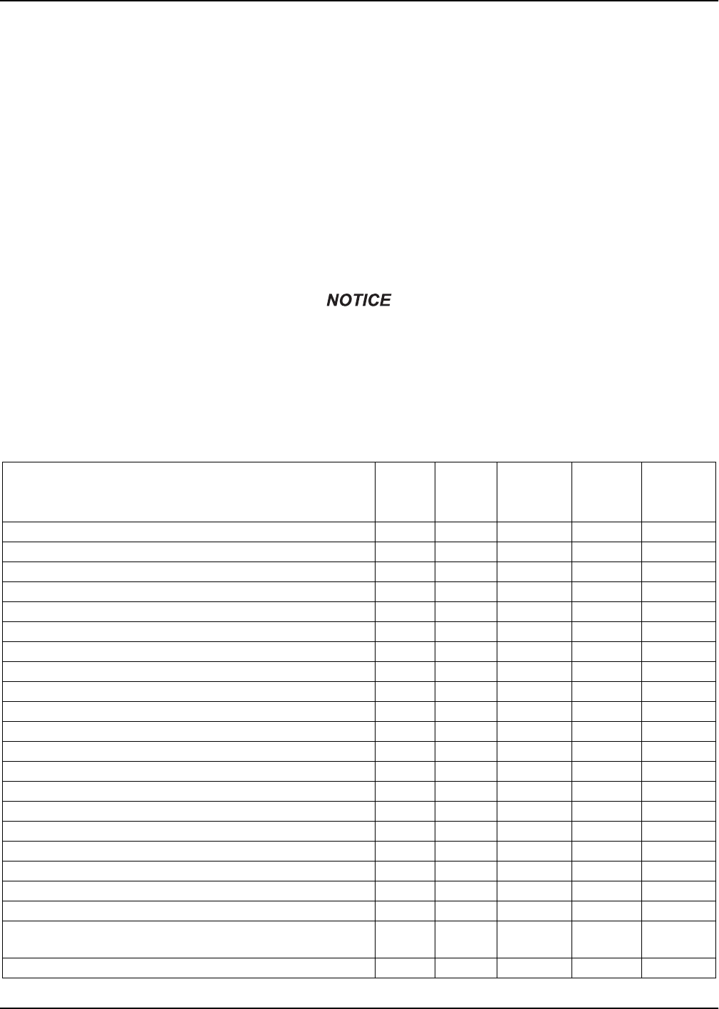
Maximum Tire Pressure psi....................................................75 ...........................................75
Specifications are subject to change without notice.
General Information
8MMG130DI4/175DI4/205DI4 Operating Manual33722 D
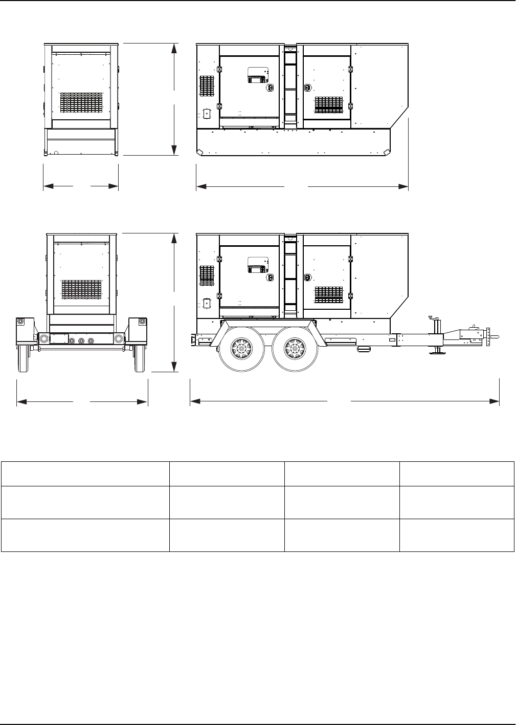
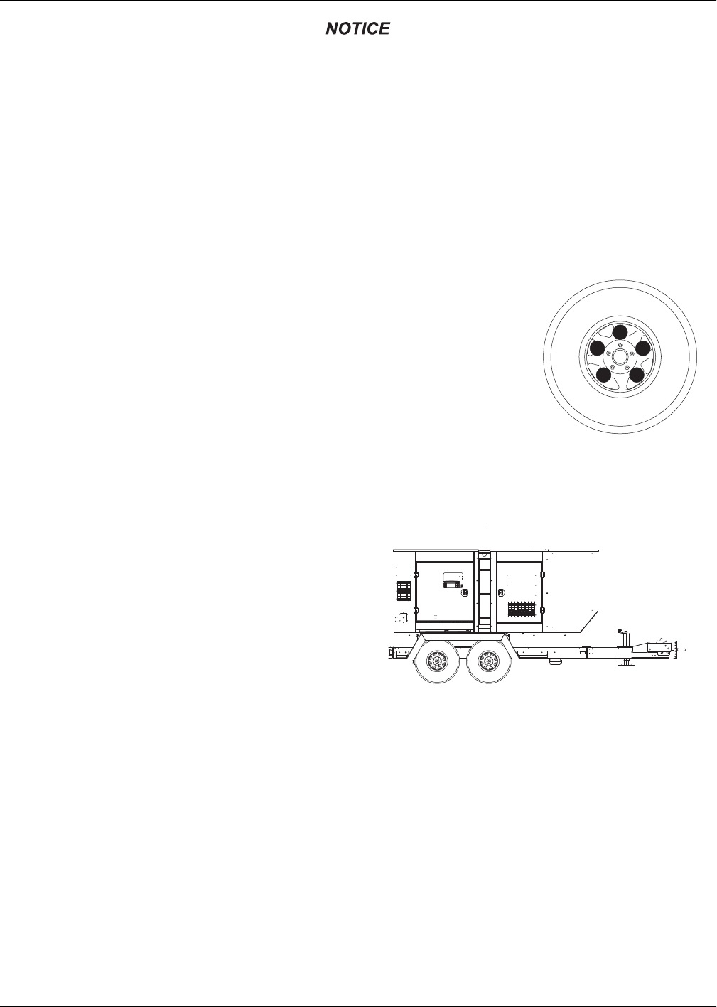
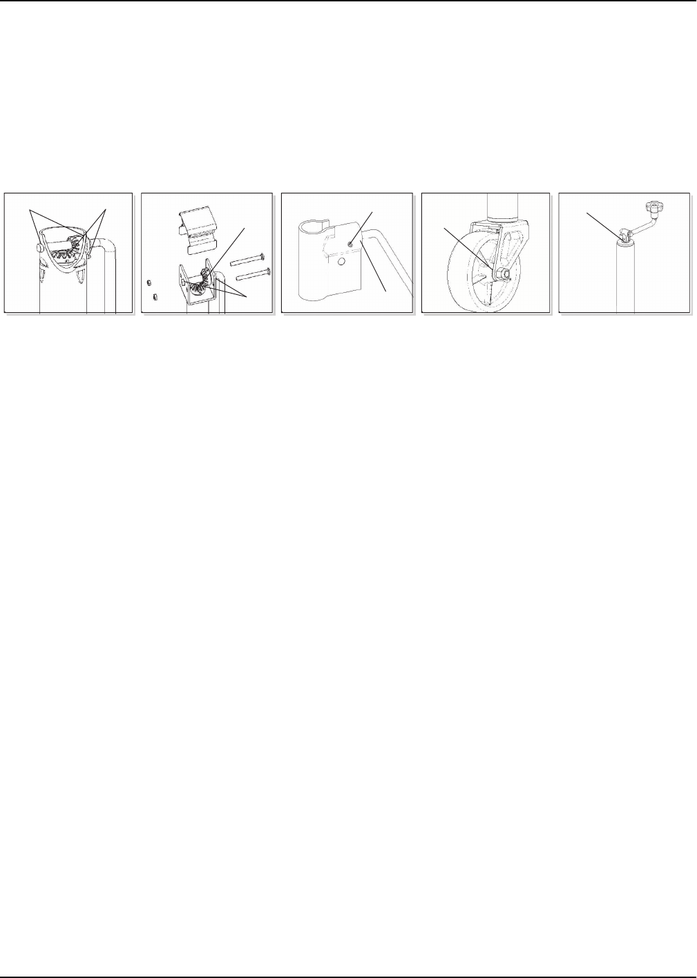
Unit Dimensions
Figure 2-1. Unit Dimensions
Specifications are subject to change without notice.
ABC
MMG130DI4/175DI4/205DI4 -
Skid Mounted
50 in. (1.27 m)77 in. (1.96 m)144 in. (3.66 m)
MMG130DI4/175DI4/205DI4 -
Trailer Mounted
86 in. (2.18 m)93 in. (2.36 m)210 in. (5.33 m)
AC
B
A
C
B
02069
General Information
33722 DMMG130DI4/175DI4/205DI4 Operating Manual9
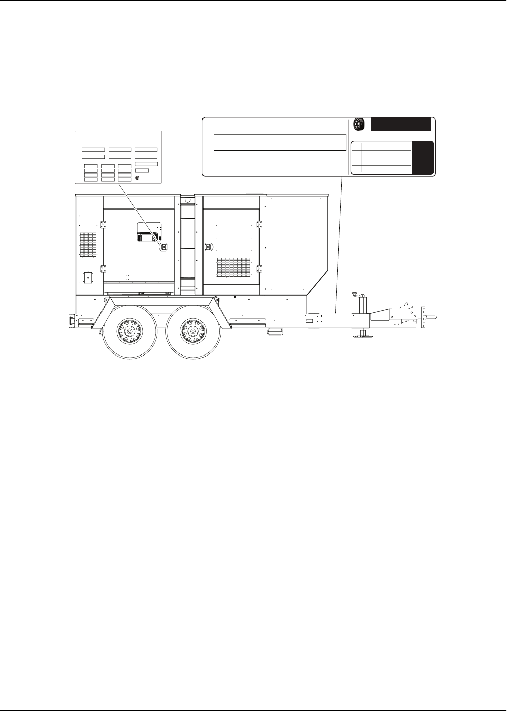
UNIT SERIAL NUMBER LOCATIONS
See Figure 2-2 for unit ID tag and Vehicle Identification Number (VIN) tag on the unit. Important information, such
as the unit serial number, model number, VIN and tire loading information are found on these tags. Record the
information from these tags so it is available if the tags are lost or damaged. When ordering parts or requesting
assistance, you may be asked to provide this information.
Figure 2-2. Serial Number Locations
VIN Tag (located on opposite side of trailer)
UNIT ID Tag
TIRE AND LOADING INFORMATION
RENSEIGNEMENTS SUR LES
PNEUS ET LE CHARGEMENT
SEE OWNER’S
MANUAL FOR
ADDITIONAL
INFORMATION
VOIR LE
MANUEL DE
L’USAGER
POUR
PLUS DE
RENSEIGNEMENTS
MANUFACTURED BY/FABRIQUE PAR:Generac Mobile Products LLCDATE: 00/0000
GVWR/PNBV: 000KG (0000LBS) COLD INF. PRESS./
PRESS. DE
V.I.N./N.I.V.:
00000000000000000
TYPE:
TRAILER
MODEL:
XXX000
GAWR / PNBE TIRE / PNEU RIM / JANTE GONF A FROID - KPA(PSI/LPC) SGL / DUAL
EACH
AXLE
THIS VEHICLE CONFORMS TO ALL APPLICABLE STANDARDS PRESCRIBED UNDER THE U.S. FEDERAL MOTOR VEHICLE SAFETY STANDARDS(FMVSS) AND CANADIAN
MOTOR VEHICLE SAFETY REGULATIONS IN EFFECT ON THE DATE OF MANUFACTURE.
CE VEHICULE EST CONFORME A TOUTES LES NORMES QUI LUI SONT APPLICABLES EN VERTU DU REGLEMENT SUR LA SECURITE DES VEHICULES AUTOMOBILES DU CANADA EN VIGUEUR A LA DATE SA
FABRICATION.
The weight of cargo should never exceed 0000KG (0000LBS)
Le poids du chargement ne doit jamais depasser 0000KG (0000LBS)
Gebruikershandleiding.com neemt misbruik van zijn services uitermate serieus. U kunt hieronder aangeven waarom deze vraag ongepast is. Wij controleren de vraag en zonodig wordt deze verwijderd.
Product:
Spelregels forum
Om tot zinvolle vragen te komen hanteren wij de volgende spelregels:
lees eerst de handleiding door;
controleer of uw vraag al eerder door iemand anders is gesteld;
probeer uw vraag zo duidelijk mogelijk te stellen;
heeft u een probleem en al geprobeerd om dit op te lossen, vermeld dit erbij aub;
heeft u een oplossing gekregen van een bezoeker dan horen wij dat graag in dit forum;
wilt u een reactie geven op een vraag of antwoord, gebruik dan niet dit formulier maar klik op de knop 'reageer op deze vraag';
uw vraag wordt direct op de website gezet; vermijd daarom persoonlijke gegevens in te vullen;
Belangrijk! Als er een antwoord wordt gegeven op uw vraag, dan is het voor de gever van het antwoord nuttig om te weten als u er wel (of niet) mee geholpen bent! Wij vragen u dus ook te reageren op een antwoord.
Belangrijk! Antwoorden worden ook per e-mail naar abonnees gestuurd. Laat uw emailadres achter op deze site, zodat u op de hoogte blijft. U krijgt dan ook andere vragen en antwoorden te zien.
Abonneren
Abonneer u voor het ontvangen van emails voor uw Generac MMG175DI4 bij:
nieuwe vragen en antwoorden
nieuwe handleidingen
U ontvangt een email met instructies om u voor één of beide opties in te schrijven.
Ontvang uw handleiding per email
Vul uw emailadres in en ontvang de handleiding van Generac MMG175DI4 in de taal/talen: Engels als bijlage per email.
De handleiding is 4,87 mb groot.
U ontvangt de handleiding per email binnen enkele minuten. Als u geen email heeft ontvangen, dan heeft u waarschijnlijk een verkeerd emailadres ingevuld of is uw mailbox te vol. Daarnaast kan het zijn dat uw internetprovider een maximum heeft aan de grootte per email. Omdat hier een handleiding wordt meegestuurd, kan het voorkomen dat de email groter is dan toegestaan bij uw provider.
Stel vragen via chat aan uw handleiding
Stel uw vraag over deze PDF
Uw handleiding is per email verstuurd. Controleer uw email
Als u niet binnen een kwartier uw email met handleiding ontvangen heeft, kan het zijn dat u een verkeerd emailadres heeft ingevuld of dat uw emailprovider een maximum grootte per email heeft ingesteld die kleiner is dan de grootte van de handleiding.
Er is een email naar u verstuurd om uw inschrijving definitief te maken.
Controleer uw email en volg de aanwijzingen op om uw inschrijving definitief te maken
U heeft geen emailadres opgegeven
Als u de handleiding per email wilt ontvangen, vul dan een geldig emailadres in.
Uw vraag is op deze pagina toegevoegd
Wilt u een email ontvangen bij een antwoord en/of nieuwe vragen? Vul dan hier uw emailadres in.