813484
1
Verklein
Vergroot
Pagina terug
1/48
Pagina verder
Conventional Flue Log Effect Stove
With Upgradeable Control Valve
Huntingdon 20/30/40
Instructions for Use, Installation and Servicing
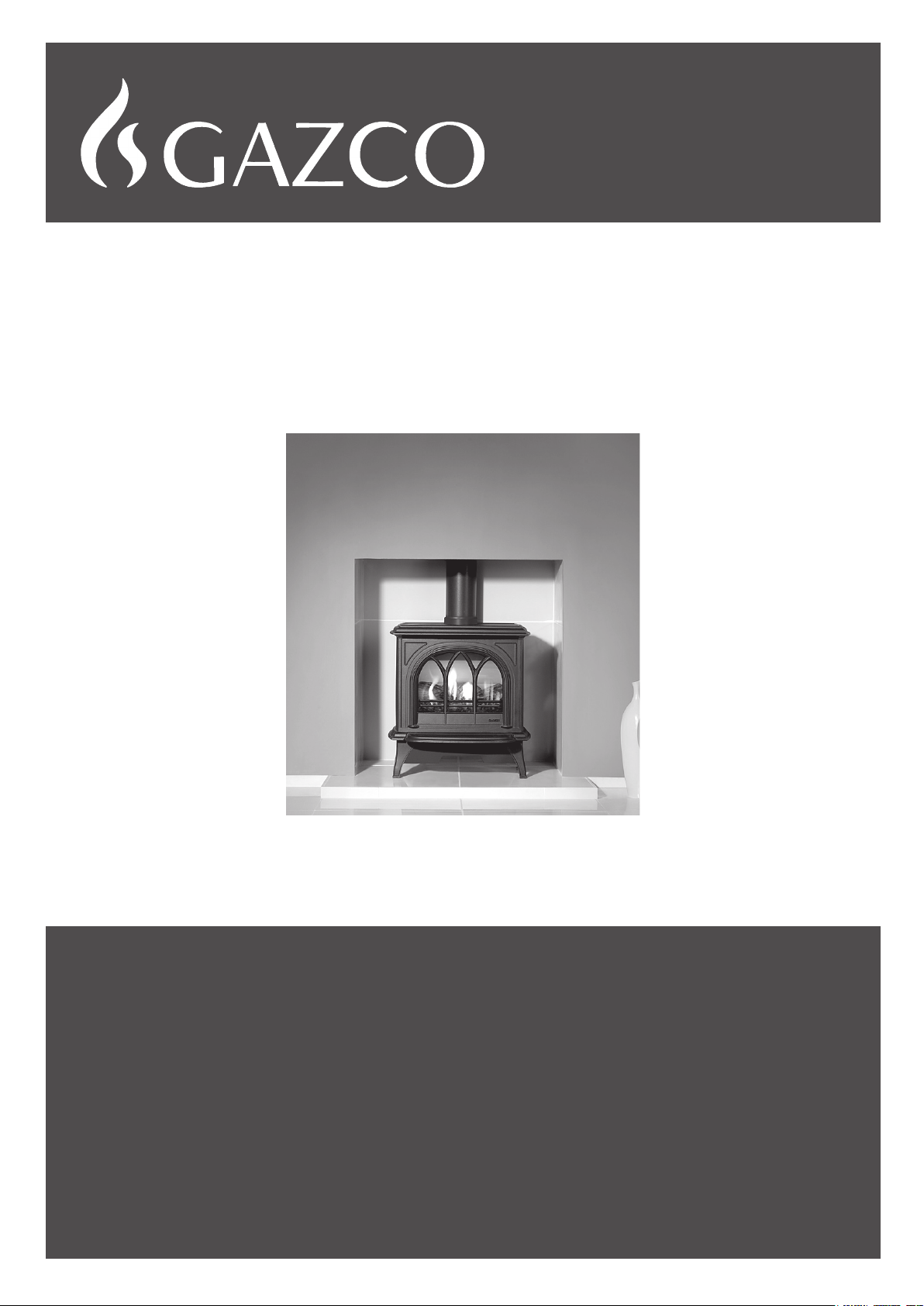
For use in GB, IE (Great Britain and Republic of Ireland)
IMPORTANT
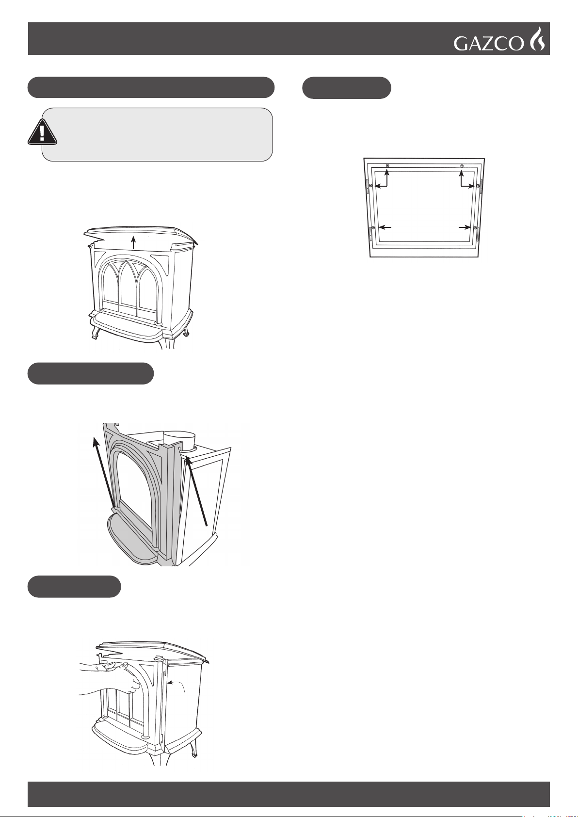
THE OUTER CASING, FRONT AND GLASS PANEL BECOME EXTREMELY HOT DURING OPERATION AND WILL RESULT IN SERIOUS
INJURY AND BURNS IF TOUCHED. IT IS THEREFORE RECOMMENDED THAT A FIREGUARD COMPLYING WITH BS 8423 (LATEST EDITION)
IS USED IN THE PRESENCE OF YOUNG CHILDREN, THE ELDERLY OR INFIRM.
ENSURE THAT ALL COMBUSTIBLE MATERIALS ARE NOT POSITIONED ABOVE OR NEAR TO THE APPLIANCE OUTER CASING.
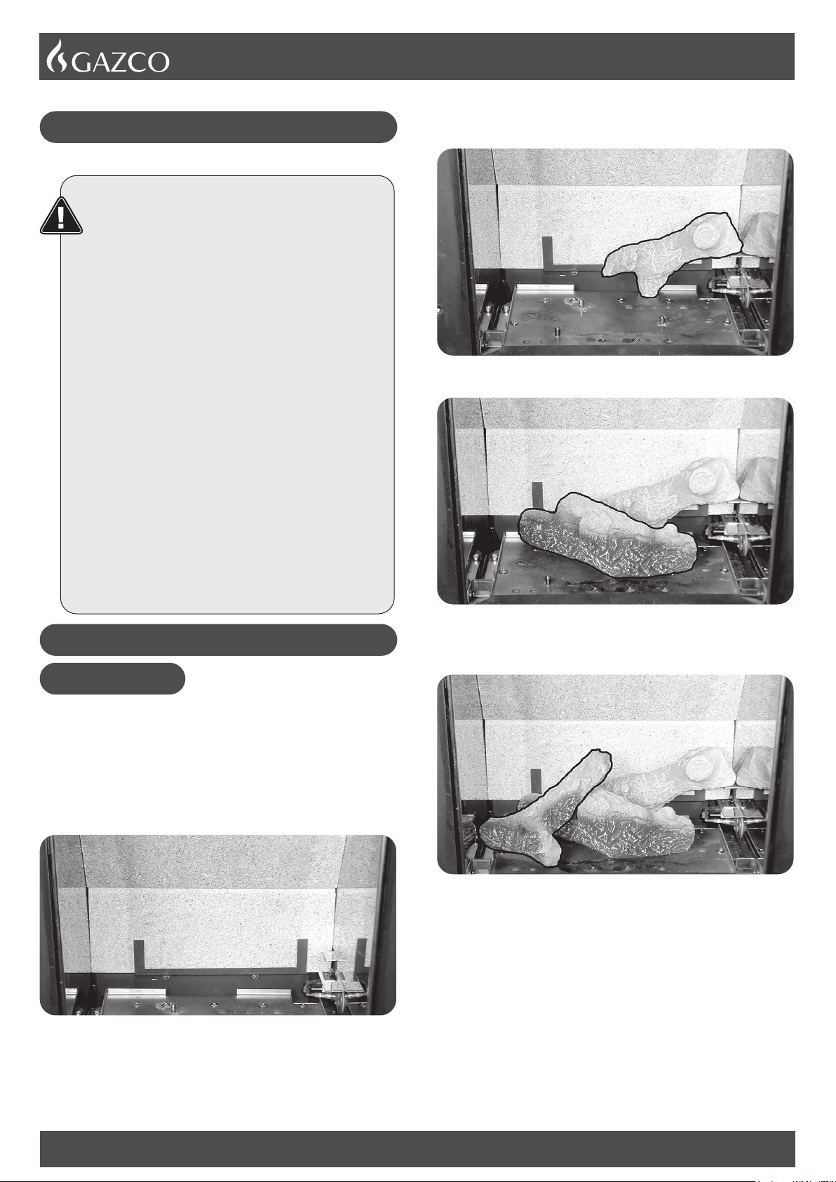
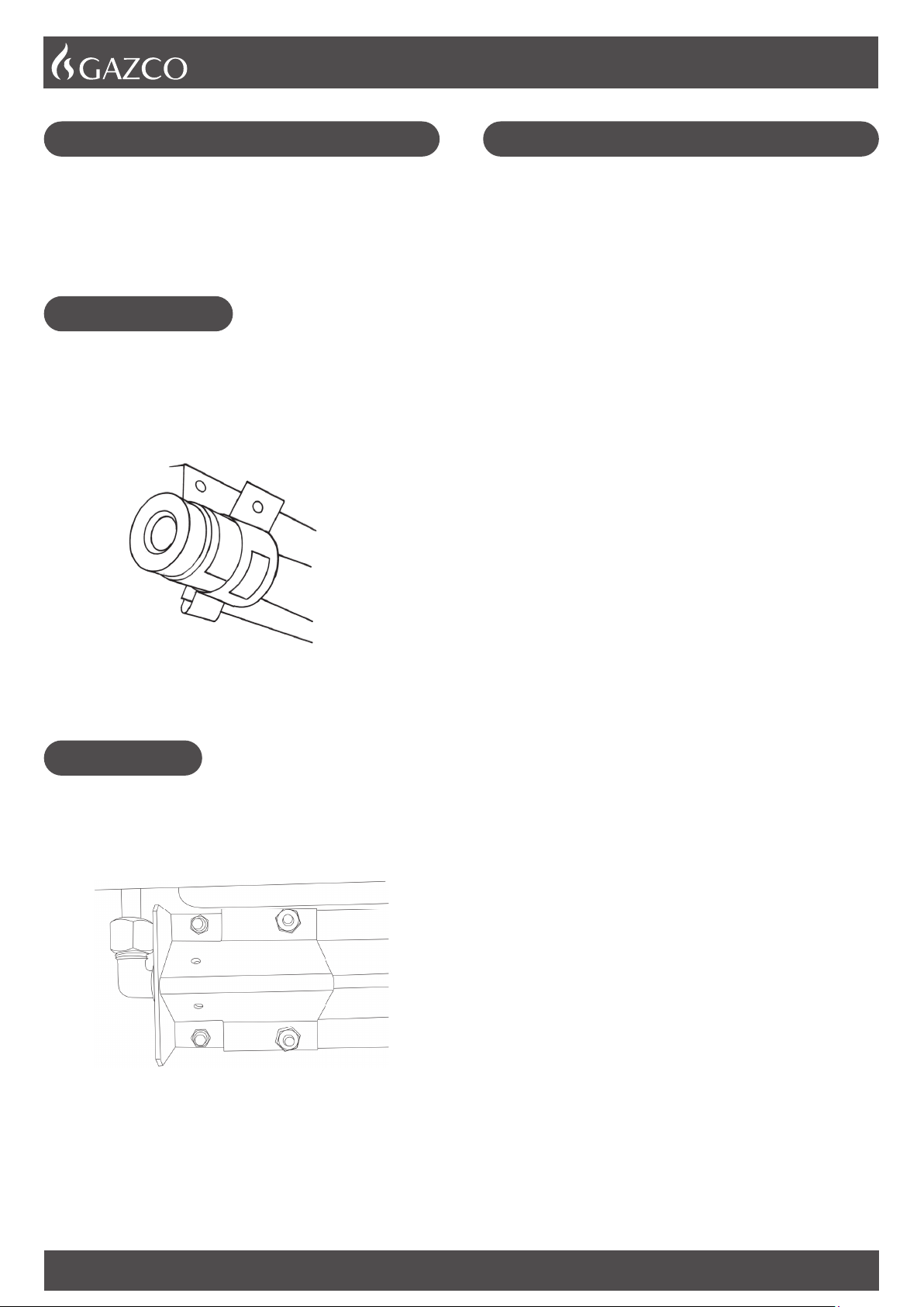
This product contains a heat resistant glass panel. This panel should be checked during Installation and at each servicing interval. If any damage is observed on the
front face of the glass panel (scratches, scores, cracks or other surface defects), the glass panel must be replaced and the appliance must not be used until a
replacement is installed. Under no circumstances should the appliance be used if any damage is observed, the glass panel is removed or broken.
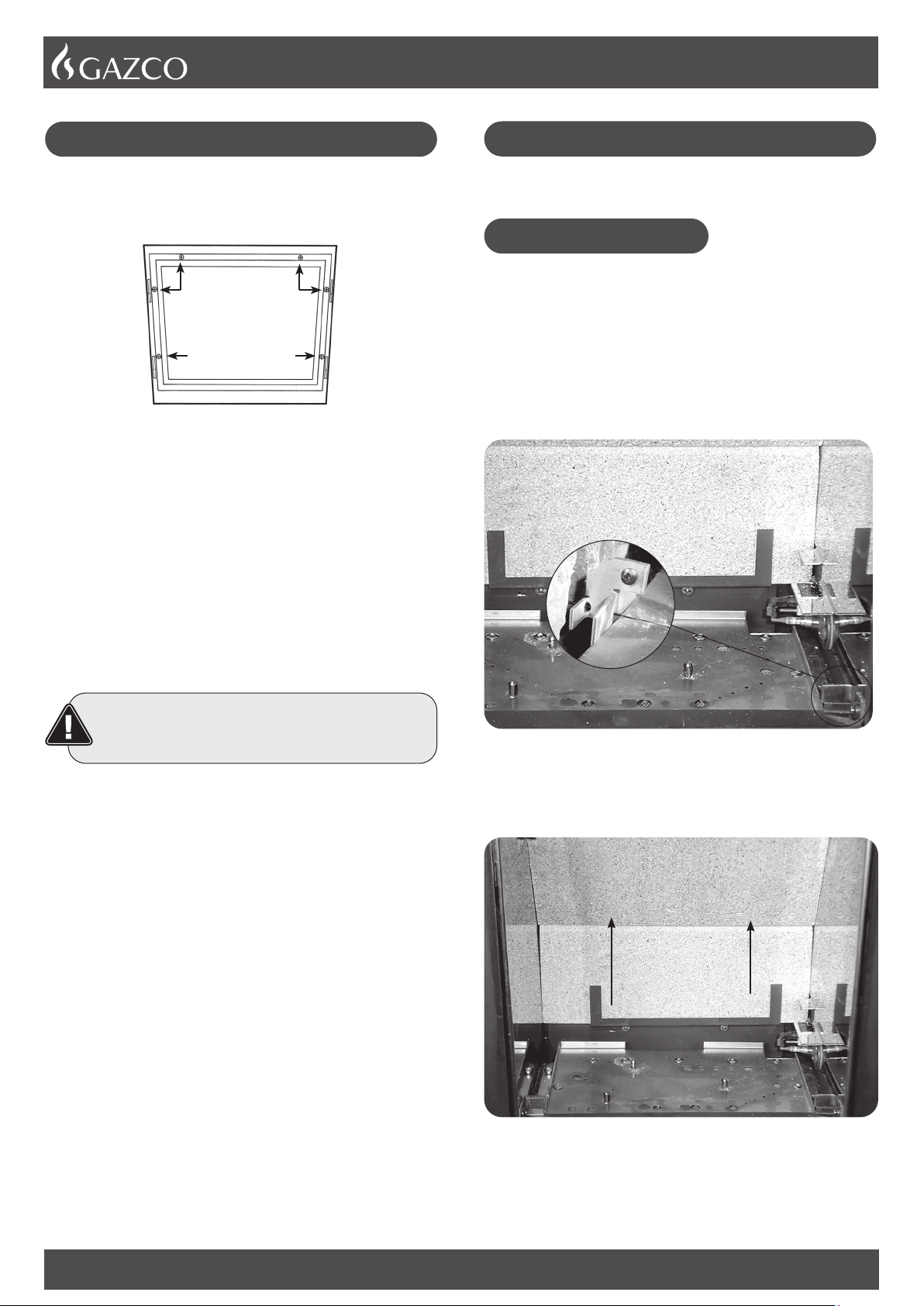
It is essential that ALL of the screws that retain the glass frame are replaced and tightened correctly. Under no circumstances should the appliance be operated if
any of these screws are loose or missing.
These Instructions must be left with the appliance for future reference and for consultation when servicing the appliance. Please make the customer aware of the
correct operation of the appliance before leaving these instructions with them.
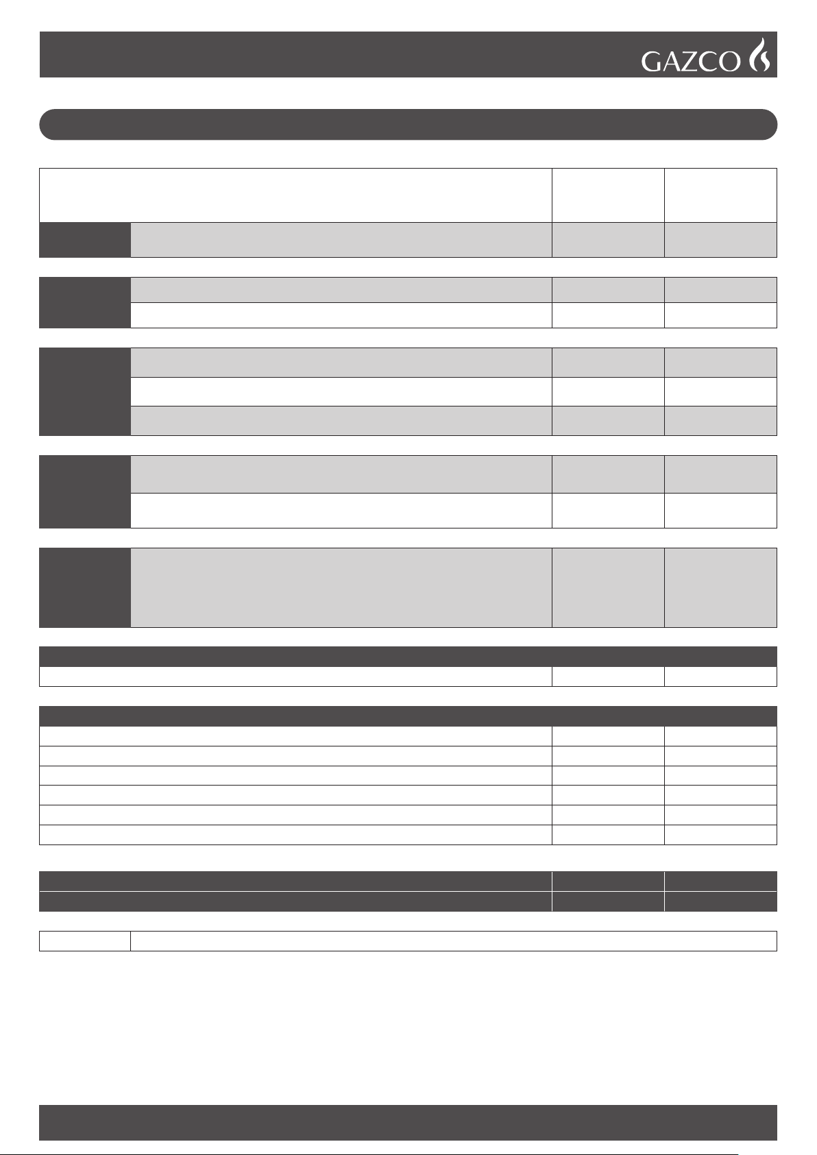
The commissioning sheet found on Page 3 of this Instruction manual must be completed by the Installer prior to leaving the premises.
PR1811.13.10.23
2
Appliance Commissioning Checklist ......................3
User Instructions .......................................................4
Installation Instructions ..........................................13
Technical Specifications ........................................................... 13
Site Requirements .................................................................... 15
Installation ................................................................................17
Commissioning ......................................................................... 26
Servicing Requirements .........................................27
Fault Finding .............................................................................27
How to replace parts ................................................................ 29
Basic spare parts list ................................................................ 39
Service Records ....................................................................... 42
Information Requirement - Gas Heaters .................................. 43
Covering the following models:
CONTENTS
It is a requirement of the Building Regulations 2010 that the installation of this appliance is notified to the Local Authority. It is
the responsibility of the GasSafe registered installer to carry out this notification to the Local Authority via the GasSafe register
Competent Persons Scheme in England and Wales (different rules apply in Scotland and Northern Ireland).
When the installation has been notified, GasSafe will send a Building Regulations Compliance Certificate to you containing
details of the work completed. Please ensure that the person responsible for the installation of this appliance completes this
notification and records it in the Appliance Commissioning Checklist on page 3.
IT IS YOUR RESPONSIBILTY TO COMPLY WITH THE BUILDING REGULATIONS AND BE ABLE TO PRODUCE THIS
CERTIFICATE SHOULD IT BE REQUIRED IN THE FUTURE.
If you have purchased your stove or fire from an authorised stockist
within our Expert Retailer Network, then automatically your product
will carry a 2 year warranty as standard. The 2 year warranty can be
further extended to a total warranty period of 5 years by registering
your Gazco Stove or Fireplace within one month of the latter of the
purchase date or installation date. Accordingly, the start date for
the warranty period is the date of purchase. During the registration
process, the Expert Retailer details will be required for your Extended
Warranty to be activated. Any product purchased outside of our Expert
Retailer Network will carry a standard 12 month, non-extendable
warranty.
It is a condition of the Extended Warranty that the installation
complies with the relevant Building Regulations and is carried out
by a suitably trained and qualified individual (GasSafe in the UK or
equivalent in other countries) with the certificate of installation and the
Commissioning Report on Page 3 completed and retained by the end
user.
Full terms and conditions are detailed in the Warranty Statement on
the Gazco website www.gazco.com. In the event of any conflict of
information the wording on the website shall prevail.
Important Note: Should any problems be experienced with your
product, claims must first be submitted to the Expert Retailer where
the appliance was purchased from who will offer immediate assistance
or contact Gazco on your behalf.
Huntingdon 20/30/40 - Conventional Flue
MODEL
HUNTINGDON 20 HUNTINGDON 30 HUNTINGDON 40
NAT GAS LPG NAT GAS LPG NAT GAS LPG
BLACK Tracery Door 515-035 515-405 515-004 515-413 515-161 515-565
Clear Door 515-071 515-441 515-009 515-453 515-188 515-592
IVORY Tracery Door 515-044 515-423 515-154 515-484 515-170 515-574
Clear Door 515-080 515-468 515-061 515-505 515-197 515-601
MATT
IVORY
Tracery Door 515-053 515-432 515-212 515-536 515-179 515-583
Clear Door 515-089 515-477 515-100 515-570 515-206 515-619
3
To assist us in any guarantee claim please complete the following information:-
APPLIANCE COMMISSIONING CHECKLIST
IMPORTANT NOTICE
Explain the operation of the appliance to the end user, hand the completed instructions to them for safe keeping,
as the information will be required when making any guaranteed claims.
Retailer ...............................................
.......................................................
.......................................................
Contact No. ...........................................
Date of Purchase .....................................
Model No. ............................................
Serial No. .............................................
Gas Type .............................................
Installation Company ................................
......................................................
......................................................
Engineer. . . . . . . . . . . . . . . . . . . . . . . . . . . . . . . . . . . . . . . . . . . . .
Contact No. ..........................................
GasSafe Reg No. ....................................
Date of Installation ..................................
RETAILER AND INSTALLER INFORMATION
FLUE CHECK PASS FAIL
1. Flue Is correct for appliance
2. Flue ow Test
3. Spillage Test
GAS CHECK
1. Gas soundness & let by test
2. Standing gas pressure mb
3. Appliance working pressure (on High Setting)
Minimum Pressure Requirement: NG - 17.5mbar LPG - 34.5mbar
NB All other gas appliances must be operating on full
mb
4. Gas rate m3/h
5. Does Ventilation meet appliance requirements
6. Have controls been upgraded (Upgradeable models only) 8455 Standard
8456 Programmable Thermostatic and Timer
YES NO
YES NO
SAFETY CHECK
1. Check soundness of the Thermocouple connections - including tightness and lead integrity
2. Glass checked to ensure no damage, scratches, scores or cracks
3. Glass frame secured correctly and all screws replaced
4. CO Alarm Fitted
BUILDING CONTROL NOTIFICATION YES NO
1. Installer notied GasSafe/Local Authority of installation via Competent Persons Scheme?
4
WELCOME
Congratulations on purchasing your Huntingdon stove, if installed
correctly Gazco hope it will give you many years of warmth and
pleasure for which it was designed.
The purpose of this manual is to familiarise you with your
appliance, and give guidelines for its installation, operation and
maintenance. If, after reading, you need further information, please
do not hesitate to contact your Gazco retailer.
WARNING
In the event of a gas escape or if you can smell
gas, please take the following steps:
• Immediately turn off the gas supply at the
meter/emergency control valve
• Extinguish all sources of ignition
• Do not smoke
• Do not operate any electrical light or power
switches (On or Off)
• Ventilate the building(s) by opening doors
and windows
• Ensure access to the premises can be made
Please report the incident immediately to the
National Gas Emergency Service Call Centre on
0800 111 999 (England, Scotland and Wales) , 0800
002 001 (N. Ireland) or in the case of LPG, the gas
supplier whose details can be found on the bulk
storage vessel or cylinder.
The gas supply must not be used until remedial
action has been taken to correct the defect and
the installation has been recommissioned by a
competent person.
GENERAL
IMPORTANT: ALWAYS WEAR THE GLOVES
PROVIDED WHEN HANDLING AN IVORY PAINTED
APPLIANCE.
Installation and servicing must only be carried out by a competent
person whose name appears on the GasSafe register. To ensure
the engineer is registered with GasSafe they should possess an ID
Card carrying the following logo:
In all correspondence, please quote the appliance type and serial
number, which can be found on the data badge located under the
top plate between the carcass and firebox or on the
Commissioning Checklist on Page 3.
Do not place curtains above the appliance:
You must have 300mm clearance between the appliance and any
curtains at either side.
The manufacturer considers the full outer casing of this appliance
to be a working surface and it will become hot whilst in operation.
A suitable guard is recommended to protect young children, the
aged and the infirm.
No furnishings or other objects should be placed within 1 metre of
the front of the appliance.
If a shelf is fitted, a distance of 225mm above the appliance is
required.
Do not attempt to burn rubbish in this appliance.
This appliance must only be operated with the door secured firmly
in position. If any cracks appear in the glass the appliance must
not be used until the glass panel is replaced.
This product is guaranteed for 5 years from the date of installation,
as set out in the terms and conditions of sale between Gazco and
your local Gazco retailer. Please consult with your local Gazco
retailer if you have any questions. In all correspondence always
quote the Model Number and Serial Number.
CO ALARMS
Building regulations require that whenever a new or replacement
fixed gas burning appliance is installed in a dwelling, a carbon
monoxide alarm complying with BS EN 50291-1(latest edition)
must be fitted in the same room as the appliance. Further guidance
and recommendations on the installation of carbon monoxide
alarms is available in BS EN 50292 (latest edition) and from
manufacturers’ instructions.
Provision of an alarm must not be considered a substitute for
either installing the appliance correctly or ensuring regular
servicing and maintenance of the appliance.
USER INSTRUCTIONS
5
OPERATING THE APPLIANCE
The control valve is at the foot on the right-hand side of the
appliance. It has two controls:
1. The right-hand knob controls the pilot ignition.
2. The left-hand knob controls the main burner.
Refer to separate instructions if your appliance is upgraded to
include battery remote control. The instructions below apply
whether or not you have the remote upgrade.
LIGHTING THE PILOT
To start the left-hand and right-hand control knobs must both point
to off ( ):
Press in the right-hand control knob and rotate anti-clockwise until
a click is heard. Continue to press in. The knob points to the pilot (
).
The pilot is lit.
Keep the knob depressed for 10 seconds before releasing. The
pilot remains lit.
Repeat the above steps if the pilot does not stay lit.
NOTE: If the pilot goes out, the Interlock system prevents you
lighting again for a short period.
If, after repeating the above steps the pilot does not light, contact
your Retailer or Installer.
Turn the right-hand knob to the left to main burner setting
().
ADJUSTING THE FLAME HEIGHT
You can now adjust the flame height and temperature using the
left-hand control knob.
Turn the left-hand knob anti-clockwise to increase the
flame height.
Turn clockwise to decrease the height.
YELLOW FLAMES APPEAR WHEN THE APPLIANCE HAS
REACHED SUFFICIENT HEAT – (10 TO 20 MINUTES).
IF THE APPLIANCE IS EXTINGUISHED OR GOES OUT IN USE,
WAIT 3 MINUTES BEFORE TRYING TO RELIGHT.
TURNING OFF THE APPLIANCE
To turn the main burner off turn the left-hand knob until it points to
off ( ). Just the pilot remains lit.
Press in and turn the right-hand knob until it points to off
(). The pilot goes out.
UPGRADING THE APPLIANCE
The appliance is fitted with a control valve that can easily be
upgraded to battery powered remote control.
There are two versions of this control which can be obtained
through your local Gazco retailer.
There is no requirement for this upgrade to be carried out by an
approved GasSafe engineer. However Gazco recommend that this
task is undertaken by a suitably competent person.
This upgrade can be fitted before or after installation but if side
clearances are limited then it will be easier to upgrade the
appliance before installation. Full instructions are included with the
kit.
If the appliance is left unattended for long periods of
time (e.g. vacation), it is recommended to place the
control valve in the Off or Pilot position.
Take care when leaving the appliance unattended,
in exceptional circumstances sound waves from
sources other than the transmitter can cause
changes in the ame height adjustment.
DO NOT install two or more appliances using
upgradeable controls in the same room, interference
between the remote control frequencies can occur.
STANDARD REMOTE CONTROL
(PART NUMBER 8455)
This remote control can control the gas appliance after the pilot
has been lit. It can turn the main burner on and regulate it from low
through to high and back again.
It can turn the main burner off leaving the pilot burning.
THERMOSTATIC AND TIMER REMOTE CONTROL
(PART NUMBER 8456)
This remote control can control the gas appliance after the pilot
has been lit.
MANUAL MODE
Can be used to turn the main burner on and manually regulate it
from low through to high and back again. It can also be used to
turn the main burner off leaving the pilot burning.
AUTO MODE
Will automatically regulate the room to a pre-set temperature.
TIMER MODE
Will turn the appliance on and off according to a pre-set
programme and automatically regulate the room temperature
during the two on periods.
6
CLEANING THE APPLIANCE
WARNING: NEVER CLEAN THE APPLIANCE
WHILE IT’S HOT. THE APPLIANCE STAYS HOT
FOR A LONG TIME AFTER SHUTDOWN.
IMPORTANT: THE OUTER PANELLING OF THE
APPLIANCE IS MADE FROM CAST IRON. USE
CAUTION WHEN INSTALLING, REMOVING AND
STORING AS THE COMPONENTS ARE HEAVY
AND SHOULD BE HANDLED CAREFULLY.
Make sure the appliance and surrounds are cool before cleaning.
REMOVING THE DOOR
For rear flue exit lift the top of the appliance off and put to one
side.
For top flue exit lift and support the top to give clearance.
HUNTINGDON 20 AND 40
Supporting the door top and bottom pull forwards whilst lifting the
front upwards at a 45° angle until it is clear of the slots and pull
away from the appliance.
HUNTINGDON 30
Lift the front upwards until it is clear of the slots and pull away from
the appliance.
ALL MODELS
Remove the glass frame by undoing the fixing screws and lifting
clear. Take care to support the glass window panel when
removing the screws.
Place carefully to one side.
Lift out the log guard.
Carefully remove the ceramic fuel bed components and set aside.
Protect the floor coverings and follow the advice given.
The logs do not require cleaning. Do not use a vacuum cleaner or
brush to clean the logs, any large pieces of debris can be removed
by hand.
Ensure any debris is removed from the burner ports.
Replace the ceramics see Log Layout section.
Ensure that the fibreglass seal on the back of the glass frame is
intact and replace the screws working from the top down. Tighten
the screws evenly DO NOT OVER TIGHTEN.
NEVER OPERATE THE APPLIANCE WHEN THE GLASS
FRAME IS REMOVED OR BROKEN.
Replace ALL of the securing screws ensuring that a screw is
present in all fixing slots.
UNDER NO CIRCUMSTANCES SHOULD THE
APPLIANCE BE USED IF ANY OF THE GLASS
FRAME RETAINING SCREWS ARE LOOSE OR
MISSING.
Use a damp cloth to clean the outer casing of the appliance.
7
CLEANING IVORY PAINTED
APPLIANCES
Allow the appliance to cool thoroughly to avoid risk of burns.
Ivory painted appliances require special attention when cleaning.
They have been coated with a high quality paint that should give
many years of service. However, this colour will mark more easily
and require cleaning more than other models.
Take care when touching the appliance to avoid marking the paint.
Most marks can be removed using a mild soap solution and a
clean lint free cloth. The finish can also be refreshed using aerosol
touch up paint (product code 2055) available from your Gazco
retailer.
ARRANGEMENT OF FUEL BED
ADVICE ON HANDLING AND DISPOSAL OF FIRE CERAMICS
The fuel effect of the log version of this
appliance is made from Refractory Ceramic
Fibre (RCF), a material which is commonly used
for this application.
Protective clothing is not required when
handling these articles, but we recommend you
follow normal hygiene rules of not smoking,
eating or drinking in the work area and always
wash your hands before eating or drinking.
To ensure that the release of RCF fibres are kept
to a minimum, during installation and servicing a
HEPA filtered vacuum is recommended to
remove any dust accumulated in and around the
appliance before and after working on it. When
servicing the appliance it is recommended that
the replaced items are not broken up, but are
sealed within heavy duty polythene bags and
labelled as RCF waste.
RCF waste is classed as stable, non-reactive
hazardous waste and may be disposed of at a
licensed landfill site.
Excessive exposure to these materials may
cause temporary irritation to eyes, skin and
respiratory tract; wash hands thoroughly after
handling the material.
LOGS MUST BE POSITIONED ACCORDING TO THE
FOLLOWING INSTRUCTIONS TO GIVE THE CORRECT FLAME
EFFECT.
LOG LAYOUT
HUNTINGDON 20
All logs can be identified by a letter (A - E) on their underside. Logs
B and E also have holes to locate each onto a burner stud.
Ensure the burner tray is clean and free from any debris.
Place Log A on the higher rear bracket and push up against the
back panel.
Place Log B over the two middle studs on the burner tray.
8
Place Log E onto the stud and behind the tag on the left hand side
of the burner tray.
Rest against Log B.
Place the small Ember at the front left of the firebox against the
rear of the log support bracket to obscure the reflection of the
burner screw.
Place the larger Ember on the lower bracket above the pilot on the
right hand side with the thicker edge facing the front and flat edges
to the base and side.
Place the foot of Log C into the rear left hand corner. The long flat
edge rests against the side of the firebox and the log touches the
back panel. The top of the log rests on Log E.
Detail A
A
Place the pointed bottom of log D into the corner of the burner tray
and rest on the location stud in log B.
Sparingly spread an amount of the Embaglow fibres provided,
covering the ports in the burner tray. Use a small piece in front of
the log on the left hand side and a long strip in front of log B.
Take care not to use more than half a packet per application.
WARNING - DO NOT PLACE NEAR THE PILOT AREA.
Embaglow
Lower log guard into position.
9
HUNTINGDON 30
Ensure the burner tray is clean and free from any debris.
The three logs that make up the fuel bed are visually distinct and fit
into specific parts on the burner tray.
Place the rear log into position between the rear brackets and
pushed up against the back panel.
Log 1
Place the second log into the left hand groove on the burner tray.
The log should butt up against the raised molding and the left hand
side liner.
Log 2
Place the third log into the groove on the right hand side.
The log should butt up against the raised molding and the right
hand side liner.
Log 3
Once the logs are in there are two embers which can be loosely
placed at the front of the fuel bed and cover the tabs securing the
burner tray.
Embers
Sparingly spread an amount of the Embaglow fibres provided,
covering the ports in the burner tray.
It is essential to cover the port in the middle of the burner tray
in order to get the most visually appealing flame picture.
Take care not to use more than half a packet per application.
WARNING - DO NOT PLACE NEAR THE PILOT AREA.
It is essential to
cover the
central port
Embaglow
10
Fix log guard into position.
HUNTINGDON 40 LAYOUT
The logs for the fuel bed are clearly individually labelled,
A to D.
Ensure the burner tray is clean and free from any debris.
There are 3 embers. Place 2 embers in the back corners of the
burner, resting in the cut outs.
Place the last ember loosely at the front of the fuel bed to cover
the hole in the centre.
Place Log D on the left hand side of the burner. There is a hole on
the underside of Log D which fits over the raised stud on the left of
the burner. The back of the log should rest flat against the back
panel.
Place Log B on top of Log D. There is a hole on the underside of
Log B which fits over the raised stud on Log D to secure in place.
The right hand side of the log rests in the groove in the burner.
Place Log C on the right hand side of the burner. There is a hole
on the underside of Log C which fits over the raised stud on the
right of the burner. The back of the log should rest flush against the
back panel.
11
Place the log guard into position on the grooves on the sides of the
firebox.
Place Log A across Log C. There is a hole on the underside of Log
A which fits over the raised stud on Log C to secure in place. The
small cut out on the left side of the log rests onto the log guard.
Once the logs are in place sparingly spread an amount of the
Embaglow fibres provided on the sections highlighted.
Take care not to use more than half a packet per application.
IT IS ESSENTIAL TO KEEP THE REAR PORT FREE FROM
OBSTRUCTION.
WARNING - DO NOT PLACE NEAR THE PILOT AREA.
Keep Rear
Port free from
Embaglow
Use a ceramic glass product generally sold for cleaning ceramic
hobs to clean the glass front.
The glass frame must be refitted to the appliance following
cleaning or servicing.
Ensure that the rope seal on the back of the glass frame is intact
and replace the screws working from the top down. Tighten the
screws evenly DO NOT OVER TIGHTEN.
Replace ALL of the securing screws ensuring that a screw is
present in all fixing slots.
UNDER NO CIRCUMSTANCES SHOULD THE
APPLIANCE BE USED IF ANY OF THE FRAME
RETAINING SCREWS ARE LOOSE OR MISSING.
NEVER OPERATE THE APPLIANCE WHEN THE GLASS
FRAME IS REMOVED, OR THE GLASS IS BROKEN.
With the top still supported or removed refit front by locating in
grooves and lowering into place.
Now replace top.
12
FLUE SURE SYSTEM
The appliance is fitted with the Gazco Flue Sure System, which will
act to cut off the gas supply to the burners in the event of incorrect
operation of the flue. If the system acts to cut off the gas supply,
this indicates that there is insufficient flue pull. If this occurs a
minimum of 10 minutes should be allowed before trying to relight.
Continued operation of this safety device means there may be a
serious problem with the flue system. A qualified GasSafe engineer
should inspect this.
DO NOT USE THE APPLIANCE UNTIL AN ENGINEER SAYS IT
IS SAFE TO DO SO.
FLAME FAILURE DEVICE
This is a safety feature incorporated on this appliance which
automatically switches off the gas supply if the pilot goes out and
fails to heat the thermocouple.
IF THIS OCCURS DO NOT ATTEMPT TO RELIGHT THE
APPLIANCE FOR 3 MINUTES.
RUNNING IN
1During initial use of a new Gazco appliance a strong odour will be
encountered as various surface coatings become hot for the first
time. Although these odours are harmless it is recommended that
the appliance is operated on maximum for 4 to 8 hours in order to
fully burn off these coatings. After this period the odours should
then disappear.
If the odours persists, please contact your installer for advice.
During the first few hours of burning there may be discolouration of
the flames. This will also disappear after a short period of use.
SERVICING
Servicing and Support
To keep your appliance looking and performing at its best, it must
be serviced annually. This service must be undertaken by a suitably
qualied individual and your retailer can organise this for you.
Alternatively, Gazco offer a manufacturers premium service with our
friendly team of qualied engineers which can be booked at
www.gazco.com/support
In all correspondence always quote the Model number and the
Serial number which may be found on the Commissioning Checklist
(Page 3).
VENTILATION
This appliance requires no additional ventilation.
INSTALLATION DETAILS
Your installer should have completed the commissioning sheet at
the front of this book. This records the essential installation details
of the appliance. In all correspondence always quote the Model
number and Serial number.
HOT SURFACES
Parts of this appliance become hot during normal use.
Regard all parts of the appliance as a ‘working surface’.
Provide a suitable fire guard to protect young children and the
infirm.
PILOT AREA WHITENING
Gas re owners (not exclusive to Gazco) have reported issues of
whitening around the pilot areas on their Conventional Flue glass
fronted products. These white marks can also appear on glass or
enamel panels inside the re and on the inside of the glass which
chemical analysis found to be Silicon Dioxide.
The cause of this is most likely a heat decomposition product of
Siloxanes or similar compounds. Gazco can conrm that there
are no Siloxane or similar products used in our conventionally
ued res and is therefore forming from sources external to the
appliance. Siloxanes can be widely found in domestic cleaning
products, cosmetics, scented room diffusers, candles and
biomethane in the natural gas supply.
To reduce this problem, Gazco would recommend the removal of
any products that could possibly contain Siloxanes from the room
the re is situated in. In addition to this, the whitening appears to
be worse when the product is left for long periods of time in the
pilot only position. This should be reduced where customers are
experiencing this problem.
13
TECHNICAL SPECIFICATION
Covering the following models:
MODEL APP.
CAT. GAS TYPE WORKING
PRESSURE AERATION INJECTOR GAS RATE
M3/H
INPUT KW
(GROSS) COUNTRY
HIGH LOW
HUNTINGDON 20
I2H Natural Gas (G20) 20mbar 1x ø6mm 185 0.314 3.3 2.0 GB, IE
I3P Propane (G31) 37mbar 6mm x 15mm 90 0.120 3.2 2.0 GB, IE
HUNTINGDON 30
I2H Natural Gas (G20) 20mbar 6mm x 6mm 260 0.433 4.55 2.5 GB, IE
I3P Propane (G31) 37mbar 1 x (14mm x 15mm) 102 0.164 4.35 2.5 GB, IE
HUNTINGDON 40
I2H Natural Gas (G20) 20mbar 2 x ø6mm 067 0.628 6.6 3.9 GB, IE
I3P Propane (G31) 37mbar 2 x ø13mm 128 0.252 6.7 3.7 GB, IE
Huntingdon 20: Efciency Class 2 - 76% / NOx Class 4
Huntingdon 30: Efciency Class 2 - 75% / NOx Class 4
Huntingdon 40: Efciency class 2 - 78%
Flue Outlet Size 127mm (5”) ø
Gas Inlet Connection Size 8mm ø
Minimum ue specication T250 / N2 / O / D / 1
Maximum ue temperature 220°C
MODEL
HUNTINGDON 20 HUNTINGDON 30 HUNTINGDON 40
NAT GAS LPG NAT GAS LPG NAT GAS LPG
BLACK Tracery Door 515-035 515-405 515-004 515-413 515-161 515-565
Clear Door 515-071 515-441 515-009 515-453 515-188 515-592
IVORY Tracery Door 515-044 515-423 515-154 515-484 515-170 515-574
Clear Door 515-080 515-468 515-061 515-505 515-197 515-601
MATT
IVORY
Tracery Door 515-053 515-432 515-212 515-536 515-179 515-583
Clear Door 515-089 515-477 515-100 515-570 515-206 515-619
The net efficiency of this appliance has been measured as specified in EN613:2001 and the result after conversion
to gross using the appropriate factor from Table E4 of SAP 2012 is 69.1% (Huntingdon 20 and 30) or 71.8%
(Huntingdon 40). The test data has been certified by Kiwa Nederland B.V. The gross efficiency value may be used in
the UK Government's Standard Assessment Procedure (SAP) for energy rating of dwellings.
INSTALLATION INSTRUCTIONS
This appliance has been certified for use in countries other than those stated. To install this appliance in these countries, it is essential to
obtain the translated instructions and in some cases the appliance will require modification. Contact Gazco for further information.
14
PACKING CHECKLIST
QTY DESCRIPTION FIXING KIT CONTAINING:-
1 x Appliance
1 x Flue infill plate
1 x Log set
1 x Packet of Embaglow
1 x Instruction manual
HUNTINGDON 40
A B C D E F G
Huntingdon 40 641 653 382 460 99 154 350
D
B
C
A
E
G
F
F
G
B
D
C
E
HUNTINGDON 20 & 30
A B C D E F G
Huntingdon 20 419 535 320 366 62 119 266
Huntingdon 30 552 592 357 402 96 174 305
A
DIMENSIONS (mm)
15
SITE REQUIREMENTS
FLUE & CHIMNEY REQUIREMENTS
The chimney or flue system must comply with the rules in force,
and must be a minimum of 127mm (5") in diameter.
The minimum flue height for the appliance must be 3 metres (10ft).
Any horizontal flue run from the rear outlet must not exceed
100mm from the back of the appliance.
A minimum of 100mm vertical flue above the top outlet spigot
should be provided before any offset of the flue.
The chimney or flue must be free from any obstruction. Any
damper plates must be removed or secured in the fully open
position, and no restrictor plates fitted.
The chimney must be swept prior to the installation, but it need not
be swept if it can be seen the chimney is clean and unobstructed
throughout its entire length.
A 5" (127mm) liner must be used if fitting the appliance into an
existing brick built chimney.
Larger lined flues can work, but in some instances could cause
cold start flue problems resulting in nuisance shutdown. Lined flues
above 7" (175mm) are not recommended.
The European chimney standards now describe chimneys and
flues by their temperature, pressure and resistance to corrosion,
condensation and fire. To identify the correct flue system, the
minimum flue specification is shown in the Technical Specification.
Existing chimneys are not covered by this system.
FLUE OPTIONS
A range of Vitreous Enamel Gloss Black flue pipe is available
to compliment the Huntingdon. Please contact your Gazco
retailer for further information.
GAS SUPPLY
THIS APPLIANCE IS INTENDED FOR USE ON A GAS
INSTALLATION WITH A GOVERNED METER.
Before installation, ensure that the local distribution conditions
(identification of the type of gas and pressure) and the adjustment
of the appliance are compatible.
Ensure the gas supply delivers the required amount of gas and is
in accordance with the rules in force.
You can use soft copper tubing on the installation and soft soldered
joints outside the appliance and below the fire.
A means of isolating the gas supply to the appliance must be
provided independent of any appliance control.
All supply gas pipes must be purged of any debris that may have
entered prior to connection to the appliance.
The gas supply must be installed in a way that does not restrict the
removal of the appliance for servicing and inspection.
VENTILATION
IMPORTANT: Ensure any national ventilation requirements are
taken into account during installation of the appliance.
UK ONLY:
The Huntingdon 30 has a nominal input not exceeding 7.0kW and
does not normally require any additional permanent ventilation.
FOR THE REPUBLIC OF IRELAND REFER TO THE RULES IN
FORCE FOR VENTILATION REQUIREMENTS.
CO ALARMS
Building regulations require that whenever a new or replacement
fixed gas burning appliance is installed in a dwelling, a carbon
monoxide alarm complying with BS EN 50291-1(latest edition)
must be fitted in the same room as the appliance. Further guidance
and recommendations on the installation of carbon monoxide
alarms is available in BS EN 50292 (latest edition) and from
manufacturers’ instructions.
Provision of an alarm must not be considered a substitute for
either installing the appliance correctly or ensuring regular
servicing and maintenance of the appliance.
APPLIANCE LOCATION
Building Regulations state this appliance must stand on a non-
combustible hearth that is at least 12mm thick and projects 50mm
minimum from the base of the appliance in all directions, however
Gazco recommend the hearth extends to the following dimensions.
C
A
B
DIMENSION A B C
Huntingdon 20 716 420 12
Huntingdon 30 853 451 12
Huntingdon 40 941 482 12
16
MINIMUM CLEARANCE
The appliance is not suitable for installation against a combustible
wall.
Ensure that all minimum clearances to combustible materials
are complied with.
The specified clearances provide the minimum distance to
combustible materials. If the appliance is intended to be installed
into a non-combustible opening the clearance to the sides and
above the appliance can be reduced. However, it is recommended
that the specified clearances are maintained irrespective of the
materials used in the construction of the opening to allow adequate
air flow and access to controls. The clearance at the rear of the
appliance must always be a minimum of 50mm.
150
225
150
50mm
150mm
In a non-combustible recess be careful to allow enough
clearance at the sides and rear of the appliance to perform
spillage tests and reach the controls.
17
SAFETY PRECAUTIONS
IMPORTANT: ALWAYS WEAR THE GLOVES
PROVIDED WHEN HANDLING AN IVORY PAINTED
APPLIANCE.
For your own and other’s safety, you must install this appliance
according to local and national codes of practice. Failure to install
the appliance correctly could lead to prosecution. Read these
instructions before installing and using this appliance.
These instructions must be left intact with the user.
Do not attempt to burn rubbish on this appliance.
Keep all plastic bags away from young children.
Do not place any object on or near to the appliance and allow
adequate clearance above the appliance.
IF THE APPLIANCE IS EXTINGUISHED OR GOES OUT IN USE,
WAIT 3 MINUTES BEFORE ATTEMPTING TO RELIGHT THE
APPLIANCE.
The appliance is fitted with the Gazco Flue Sure System, which will
act to cut off the gas supply to the burners in the event of incorrect
operation of the flue. If the system acts to cut off the gas supply,
this indicates that there is insufficient flue pull. If this occurs a
minimum of 10 minutes should be allowed before trying to relight.
Continued operation of this safety device means there may be a
serious problem with the flue system. A qualified GasSafe engineer
should inspect this.
Do not alter or tamper with the Flue Sure System. Use only
genuine Gazco replacement parts when servicing the system -
refer to the Servicing Section, Replacing Parts.
DO NOT USE THE APPLIANCE UNTIL AN ENGINEER SAYS IT
IS SAFE TO DO SO.
IMPORTANT: REFER TO DATA BADGE AND
TECHNICAL SPECIFICATION AT THE FRONT OF
THE MANUAL TO ENSURE THE APPLIANCE IS
CORRECTLY ADJUSTED FOR THE GAS TYPE AND
CATEGORY APPLICABLE IN THE COUNTRY OF
USE.
UNPACKING
Remove the appliance from its packaging, and check that it is
complete and undamaged.
Put the loose ceramic parts to one side so that they are not
damaged during installation.
UPGRADING THE APPLIANCE
The appliance is fitted with a control valve that can easily be
upgraded to battery powered remote control.
There are two versions of this control which can be obtained
through your local Gazco retailer.
There is no requirement for this upgrade to be carried out by an
approved GasSafe engineer. However Gazco recommend that this
task is undertaken by a suitably competent person.
This upgrade can be fitted before or after installation but if side
clearances are limited then it will be easier to upgrade the
appliance before installation. Full instructions are included with the
kit.
If the appliance is left unattended for long periods of
time (e.g. vacation), it is recommended to place the
control valve in the Off or Pilot position.
Take care when leaving the appliance unattended,
in exceptional circumstances sound waves from
sources other than the transmitter can cause
changes in the ame height adjustment.
DO NOT install two or more appliances using
upgradeable controls in the same room, interference
between the remote control frequencies can occur.
STANDARD REMOTE CONTROL
(PART NUMBER 8455)
This remote control can control the gas appliance after the pilot
has been lit. It can turn the main burner on and regulate it from low
through to high and back again.
It can turn the main burner off leaving the pilot burning.
THERMOSTATIC AND TIMER REMOTE CONTROL
(PART NUMBER 8456)
This remote control can control the gas appliance after the pilot
has been lit.
MANUAL MODE
Can be used to turn the main burner on and manually regulate it
from low through to high and back again. It can also be used to
turn the main burner off leaving the pilot burning.
AUTO MODE
Will automatically regulate the room to a pre-set temperature.
TIMER MODE
Will turn the appliance on and off according to a pre-set
programme and automatically regulate the room temperature
during the two on periods.
INSTALLATION
18
INSTALLATION OF THE APPLIANCE
Decide whether to use top or rear flue exit.
The appliance is factory built for rear flue exit but it can be
changed to top exit by swapping the flue spigot and blanking plate
located on the appliance.
HUNTINGDON 30 ONLY
On Huntingdon 30 models the flue spigot must be placed in an
offset position from the blanking plate to correctly align with the top
plate.
To access the blanking plate lift off the cast top and place carefully
to one side.
Remove the four screws holding the blanking plate to the
appliance.
Note the two additional holes in the top of the firebox.
With the blanking plate removed there are a two additional holes
underneath.
Position the flue spigot using the offset holes and the ones
previously beneath the blanking plate. Secure the spigot and
blanking plate in the new positions.
ALL MODELS
Position the appliance ensuring all appropriate clearances are
observed.
Having run the gas supply to the appliance PURGE THE SUPPLY
PIPE.
This is essential to expel any debris that can block the gas
controls.
Connect the gas supply to the 8mm compression elbow at the
right-hand rear corner of the appliance.
There is a cutout in the right-hand rear leg to enable a straight
connection to the rear of the appliance.
The flue system can now be connected to the appliance.
Ensure all joints are sealed with a fire resistant cement and use a
self-tapping screw at the flue spigot joint.
GAS SOUNDNESS PRESSURE CHECK
Connect a suitable pressure gauge to the test point located on the
inlet fitting and turn the gas supply on. Light the appliance and
check all gas joints for possible leaks. Turn the appliance to
maximum and check that the supply pressure is as stated on the
databadge. Turn the gas off and replace the test point screw, turn
the gas on and check the test point for leaks.
19
REMOVING THE DOOR
IMPORTANT: THE OUTER PANELLING OF THE
APPLIANCE IS MADE FROM CAST IRON. USE
CAUTION WHEN INSTALLING, REMOVING AND
STORING AS THE COMPONENTS ARE HEAVY
AND SHOULD BE HANDLED CAREFULLY.
For rear flue exit lift the top of the appliance off and put to one
side.
For top flue exit lift and support the top to give clearance.
HUNTINGDON 20 AND 40
Lift the front upwards until it is clear of the slots and pull away from
the appliance.
HUNTINGDON 30
Lift the front upwards until it is clear of the slots and pull away from
the appliance.
ALL MODELS
Remove the glass frame by undoing the fixing screws and lifting
clear. Take care to support the glass window panel when
removing the screws.
20
ARRANGEMENT OF FUEL BED
ADVICE ON HANDLING AND DISPOSAL OF FIRE CERAMICS
The fuel effect of the log version of this
appliance is made from Refractory Ceramic
Fibre (RCF), a material which is commonly
used for this application.
Protective clothing is not required when
handling these articles, but we recommend you
follow normal hygiene rules of not smoking,
eating or drinking in the work area and always
wash your hands before eating or drinking.
To ensure that the release of RCF fibres are
kept to a minimum, during installation and
servicing a HEPA filtered vacuum is
recommended to remove any dust
accumulated in and around the appliance
before and after working on it. When servicing
the appliance it is recommended that the
replaced items are not broken up, but are
sealed within heavy duty polythene bags and
labelled as RCF waste.
RCF waste is classed as stable, non-reactive
hazardous waste and may be disposed of at a
licensed landfill site.
Excessive exposure to these materials may
cause temporary irritation to eyes, skin and
respiratory tract; wash hands thoroughly after
handling the material.
LOG LAYOUT
HUNTINGDON 20
LOGS MUST BE POSITIONED ACCORDING TO THE
FOLLOWING INSTRUCTIONS TO GIVE THE CORRECT FLAME
EFFECT.
All logs can be identified by a letter (A - E) on their underside.
Logs, B and E also have holes to locate each onto a burner stud.
Ensure the burner tray is clean and free from any debris.
Place Log A on the higher rear bracket and push up against the
back panel.
Place Log B over the two middle studs on the burner tray.
Place Log E onto the stud and behind the tag on the left hand side
of the burner tray.
Rest against Log B.
21
Place the small Ember at the front left of the firebox, against the
rear of the log support bracket to obscure the reflection of the
burner screw.
Place the larger Ember on the lower bracket above the pilot on the
right hand side with the thicker edge facing the front and flat edges
to the base and side.
Place the foot of Log C into the rear left hand corner. The long flat
edge rests against the side of the firebox and the log touches the
back panel. The top of the log rests on Log E.
Detail A
A
Place the pointed bottom of log D into the corner of the burner tray
and rest on the location stud on log B.
Sparingly spread an amount of the Embaglow fibres provided,
covering the ports in the burner tray. Use a small piece in front of
the log on the left hand side and a long strip in front of log B.
Take care not to use more than half a packet per application.
WARNING - DO NOT PLACE NEAR THE PILOT AREA.
Embaglow
Lower log guard into position.
22
HUNTINGDON 30
Ensure the burner tray is clean and free from any debris.
The three logs that make up the fuel bed are visually distinct and fit
into specific parts on the burner tray.
Place the rear log into position between the rear brackets and
pushed up against the back panel.
Log 1
Place the second log into the left hand groove on the burner tray.
The log should butt up against the raised molding and the left hand
side liner.
Log 2
Place the third log into the groove on the right hand side.
The log should butt up against the raised molding and the right
hand side liner.
Log 3
Once the logs are in there are two embers which can be loosely
placed at the front of the fuel bed and cover the tabs securing the
burner tray.
Embers
Sparingly spread an amount of the Embaglow fibres provided,
covering the ports in the burner tray.
It is essential to cover the port in the middle of the burner tray
in order to get the most visually appealing flame picture.
Take care not to use more than half a packet per application.
WARNING - DO NOT PLACE NEAR THE PILOT AREA.
It is essential to
cover the
central port
Embaglow
23
Place Log D on the left hand side of the burner. There is a hole on
the underside of Log D which fits over the raised stud on the left of
the burner. The back of the log should rest flat against the back
panel.
Place Log B on top of Log D. There is a hole on the underside of
Log B which fits over the raised stud on Log D to secure in place.
The right hand side of the log rests in the groove in the burner.
Place Log C on the right hand side of the burner. There is a hole
on the underside of Log C which fits over the raised stud on the
right of the burner. The back of the log should rest flush against the
back panel.
Fix log guard into position.
HUNTINGDON 40
The logs for the fuel bed are clearly individually labelled,
A to D.
Ensure the burner tray is clean and free from any debris.
There are 3 embers. Place 2 embers in the back corners of the
burner, resting in the cut outs.
Place the last ember loosely at the front of the fuel bed to cover
the hole in the centre.
24
Place the log guard into position on the grooves on the sides of the
firebox.
Place Log A across Log C. There is a hole on the underside of Log
A which fits over the raised stud on Log C to secure in place. The
small cut out on the left side of the log rests onto the log guard.
Once the logs are in place sparingly spread an amount of the
Embaglow fibres provided on the sections highlighted.
Take care not to use more than half a packet per application.
IT IS ESSENTIAL TO KEEP THE REAR PORT FREE FROM
OBSTRUCTION.
WARNING - DO NOT PLACE NEAR THE PILOT AREA.
Keep Rear
Port free from
Embaglow
COMPLETION OF ASSEMBLY
Ensure the rope seal fitted to the rear of the glass frame is intact.
Use a ceramic glass product generally sold for cleaning ceramic
hobs to clean the glass front.
Refit glass frame and tighten screws evenly.
NEVER OPERATE THE APPLIANCE WHEN THE GLASS
FRAME IS REMOVED, OR THE GLASS IS BROKEN.
Ensure that the fibreglass seal on the back of the glass frame and
replace the screws working from the top down. Tighten the screws
evenly DO NOT OVER TIGHTEN.
NEVER OPERATE THE APPLIANCE WHEN THE GLASS
FRAME IS REMOVED OR BROKEN.
Replace ALL of the securing screws ensuring that a screw is
present in all fixing slots.
UNDER NO CIRCUMSTANCES SHOULD THE
APPLIANCE BE USED IF ANY OF THE GLASS
FRAME RETAINING SCREWS ARE LOOSE OR
MISSING.
With the top still supported or removed refit front by locating in
grooves and lowering into place.
Now replace top.
25
OPERATING THE APPLIANCE
The control valve is at the foot on the right-hand side of the
appliance. It has two controls.
1. The right-hand knob controls the pilot ignition.
2. The left-hand knob controls the main burner.
Refer to separate instructions if your appliance is upgraded to
include battery remote control. The instructions below apply
whether or not you have the remote upgrade.
LIGHTING THE PILOT
To start the left-hand and right-hand control knobs must both point
to off ( ):
Press in the right-hand control knob and rotate anti-clockwise until
a click is heard. Continue to press in. The knob points to the pilot
().
The pilot is lit.
Keep the knob depressed for 10 seconds before releasing. The
pilot remains lit.
Repeat the above steps if the pilot does not stay lit.
NOTE: If the pilot goes out, the Interlock system prevents you
lighting again for a short period.
If, after repeating the above steps the pilot does not light, contact
your Retailer or Installer.
Turn the right-hand knob to the left to main burner setting
().
ADJUSTING THE FLAME HEIGHT
You can now adjust the flame height and temperature using the
left-hand control knob.
Turn the left-hand knob anti-clockwise to increase the
flame height.
Turn clockwise to decrease the height.
IMPORTANT: YELLOW FLAMES TYPICALLY
APPEAR WHEN THE APPLIANCE HAS REACHED
NORMAL OPERATING TEMPERATURE. THIS CAN
TAKE UP TO 30 MINUTES.
WARNING: IF THE APPLIANCE FAILS TO LIGHT OR
BECOMES EXTINGUISHED IN USE, WAIT 3
MINUTES BEFORE ATTEMPTING TO RELIGHT.
26
COMMISSIONING
Close all doors and windows in the room.
Ignite the appliance and operate on maximum for 10 minutes.
Position a lighted smoke match just inside the draught diverter
opening at the rear of the appliance.
Check all smoke is drawn into the opening.
Rear of Appliance
Draft diverter lip
Smoke match
If there is any doubt, run the appliance for a further 10 minutes, and
repeat the test.
If there are any extractor fans in adjacent rooms, the test must be
repeated with the fans running on maximum and interconnecting
doors open.
IF SPILLAGE PERSISTS, DISCONNECT THE APPLIANCE AND
SEEK EXPERT ADVICE.
Complete the Commissioning Checklist at the front of this manual
covering:
— Thermocouple soundness checks.
This is to include ensuring the thermocouple is secure on
the pilot bracket assembly, lead connection and integrity.
— Flue checks
— Gas checks
— Log layout - flame picture
Upon completion of the commissioning and testing of the
installation and correct operation of the appliance, the installer
must instruct the user how to operate the appliance.
Guide the user through the User Instructions paying particular
attention to:
a) Regular servicing.
b) Ventilation - point out the ventilation positions where
applicable.
c) Hot surfaces.
27
SERVICING REQUIREMENTS
IMPORTANT – The glass panel on this appliance should be
checked for any signs of damage on the front face of the
glass panel (scratches, scores, cracks or other surface
defects). If damage is observed, the glass panel must be
replaced and the appliance must not be used until a
replacement is installed. Under no circumstances should the
appliance be used if any damage is observed. Please isolate
the appliance until a replacement glass panel has been
obtained and installed. Replacement glass panels can be
purchased from Gazco via the retailer from which the
appliance was purchased or any other Gazco distributor.
This appliance must be serviced at least once a year by a
competent person.
All tests must be carried out in accordance with the current
GasSafe recommendations.
Before Testing:
Conduct a gas soundness test for the property ensuring
there are no leaks before servicing.
Check the operation of the appliance before testing.
Special checks:
Clean the burner using a vacuum cleaner with a soft
brush attachment. Ensure all debris is removed from
the burner ports.
Clean away lint or fluff from the pilot.
Clean away lint or fluff from under the burner.
Check the spark gap on the pilot is correct.
Ensure that the glass frame is secured correctly and that
all retaining screws are in place.
Correct any faults found during the initial test.
Re-commission the appliance in accordance with Commissioning
Procedures.
Advise the customer of any remedial work undertaken.
13mm
Huntingdon 20 & 30 Huntingdon 40
7mm
30mm
10mm
10mm
IGNITION FUNCTIONAL CHECK 1
PILOT WILL NOT LIGHT
Ensure there is no debris around the pilot assembly,
(e.g. soot, etc.) which could short the spark, clean the
area.
Operate the valve.
Is there a spark?
Consult User
Instructions and retry.
Check alignment of pilot
burner head, change the
ignition lead,
See '
Ignition Lead'
section of
Replacing Part
s.
Check isolation tap and
gas meter, retry.
Correct and
retry.
Purge the gas pipes and
retry.
GO TO THE NEXT
CHART IGNITION
FUNCTIONAL CHECK 2
SYSTEM OK
There is a blockage in the system, check the inlet test point,
the mag seating, valve and pilot filter.
Is the gas turned on to the
appliance?
Is the gas pressure correct?
Has the system got
any air in it?
Does the pilot light?
Is the control being
operated correctly?
Will the pilot light
with a match?
No Yes
No
Yes
No
Yes
Yes
No
No
Yes
No
No
Yes
Yes
SERVICING INSTRUCTIONS
28
FLAME FAILURE FUNCTIONAL CHECK 3
IGNITION FUNCTIONAL CHECK 2
Remove the electrode lead
from the piezo. Operate the
valve. Does a spark jump from
the piezo to the valve body?
Replace the piezo
and gas valve and retry.
Yes No
PILOT WILL NOT STAY LIT OR FIRE GOES OUT IN USE
Ensure there is no debris around the pilot assembly,
(e.g. soot etc.) Check for fluff in the pilot aeration hole.
See the Diagram in the Replacing Parts section.
Problem is with the
pipe work or
fittings which lead
to the appliance.
Correct
and retry.
Is thermocouple
connection good
in back of valve?
Replace
thermocouple.
Will pilot
stay alight?
Change mag
unit.
Is the pilot flame of
the correct length?
See Servicing
Requirements
Diagram page 27.
Change the
pilot unit.
Will pilot
stay alight?
With the pilot
running is the gas
pressure as stated
on the data
badge?
With the appliance
running on full is the
gas at the pressure
stated on the data
badge?
Run for no more
than 60 seconds
turn off, time interval
until mag unit shuts
with a click. Is this
greater than 7
seconds?
Run for a maximum of
60 seconds, turn off,
time interval until mag
unit shuts with a click.
Is this greater than 7
seconds?
Tighten the
connection and retry.
No
No
No
No
No
No
Yes
SYSTEM OK
Yes
Yes
Yes
Yes
No
Yes
Yes
No
Light the pilot and keep the control knob pushed in
at least 10 seconds before releasing.
NO SPARK
Ensure there is no debris around the pilot assembly,
(e.g. soot etc.) which could short the spark, clean the area.
Consult the users
instructions, retry.
Operate the valve to light
the pilot, does the valve
'click'?
Is the pIlot burner
horizontal?
see Diagram page 27.
Has ignition lead
become detached or is
connection poor?
Remove the ignition lead
from electrode with insulated
pliers. Hold the tip 4mm from the
pilot pipework, is there a spark
when the valve ‘clicks’?
Is the electrode wire
detached from the piezo
in the valve?
Replace the combined
lead and piezo, retry.
Correct and retry.
Check for defective or
damaged control knob spindle
or cam operation. Check for
correct location of piezo
components. Correct and retry.
Is the control system being
operated correctly?
Reset the pilot burner.
Yes
Yes
Yes
No
No
No
Yes
Yes
Yes
No
No
Replace the electrode. Replace the electrode
lead and retry.
Is the flue working?
Rectify flue.
No
Yes
Yes
FAULT FINDING CHARTS
29
GENERAL
IMPORTANT: ALWAYS WEAR THE GLOVES
PROVIDED WHEN HANDLING AN IVORY PAINTED
APPLIANCE.
All main components can be replaced without removing the
appliance from its installation.
Ensure the appliance and surrounds are cool before servicing.
IT IS ESSENTIAL THAT THE GAS SUPPLY TO THE APPLIANCE
IS TURNED OFF AT THE ISOLATION DEVICE BEFORE
PROCEEDING FURTHER.
To service the gas valve and controls the decorative trim can be
removed to allow easier access. To do this remove the two screws
and gently pull away from the appliance.
REMOVING THE DOOR
IMPORTANT: THE OUTER PANELLING OF THE
APPLIANCE IS MADE FROM CAST IRON. USE
CAUTION WHEN INSTALLING, REMOVING AND
STORING AS THE COMPONENTS ARE HEAVY
AND SHOULD BE HANDLED CAREFULLY.
For rear flue exit lift the top of the appliance off and put to one
side.
For top flue exit lift and support the top to give clearance.
HUNTINGDON 20 AND 40
Lift the front upwards until it is clear of the slots and pull away from
the appliance.
HUNTINGDON 30
Lift the front upwards until it is clear of the slots and pull away from
the appliance.
REPLACING PARTS
30
WINDOW FRAME ASSEMBLY
Remove the glass frame by undoing the fixing screws and lifting
clear. Take care to support the glass window panel when
removing the screws.
Place carefully to one side.
Lift out the log retainer and carefully remove the ceramic fuel bed
components.
Refit in reverse order.
Ensure that the fibreglass seal on the back of the glass frame and
replace the screws working from the top down. Tighten the screws
evenly DO NOT OVER TIGHTEN.
NEVER OPERATE THE APPLIANCE WHEN THE GLASS
FRAME IS REMOVED OR BROKEN.
Replace ALL of the securing screws ensuring that a screw is
present in all fixing slots.
UNDER NO CIRCUMSTANCES SHOULD THE
APPLIANCE BE USED IF ANY OF THE GLASS
FRAME RETAINING SCREWS ARE LOOSE OR
MISSING.
BAFFLE & CERAMIC LINERS
To access the burner tray and interior workings of the appliance it
may be necessary to remove the baffle and the liners.
HUNTINGDON 20 - LINERS
BAFFLE
There is no requirement to remove the baffle for servicing.
LINERS
The burner can be accessed without the need to remove the side
liner panels. If they need to be taken out then first remove the
screws securing the two brackets on either side of the firebox.
The panels will now slide forward.
Gently lift the upper rear liner and pull forwards.
With the panel raised it should be possible to remove from the liner
brackets.
Note: It may be necessary to use a flat object like a screwdriver to
separate the two panels.
31
Slide the lower rear liner up and out of the lower bracket.
Replace all parts in reverse order ensuring the cutouts in the rear
of the lower panel fit over the screws on the back of the firebox.
HUNTINGDON 30
- BAFFLE & LINERS
BAFFLE
The baffle must be removed before the liners can be taken out of
the appliance.
To do this undo the two screws securing it to the roof of the firebox.
Screws
The baffle can now be removed through the front of the appliance.
CERAMIC LINERS
Once the baffle has been placed carefully to one side the liners
can then been taken out in the following order.
To remove the Left Hand liner first tilt inwards towards the centre of
the firebox before lifting up and pulling out through the front of the
firebox.
To remove the Right Hand liner first tilt inwards towards the centre
of the firebox before lifting up and pulling out through the front of
the firebox.
The two side liners also support the raised rear liner.
Taking out the side liners will allow the rear liner to drop down so
ensure it is supported and removed carefully.
32
The lower rear liner does not need to be removed from the bracket
in order to access the burner tray for maintenance, but can be
lifted off in order to clean or replace.
With the liners and baffle removed the firebox is clear for cleaning
and maintenance.
To replace the liners liner and baffle reverse these procedures.
HUNTINGDON 40
- BAFFLE & LINERS
To access the burner tray and interior workings of the appliance it
may be necessary to remove the baffles and the liners.
This appliance has 2 baffles, 1 metal and 1 vermiculite, that must
be removed before the liners can be taken out of the appliance.
Remove the logs.
METAL BAFFLE
To remove the metal baffle:
Undo the 3 screws securing it to the roof of the firebox.
ScrewsScrews
The baffle can now be removed through the front of the appliance.
VERMICULITE BAFFLE
To remove the vermiculite baffle:
Lift the vermiculite baffle and slide out through the front of the
appliance.
Once the baffles have been placed carefully to one side the liners
can then been taken out in the following order.
33
REFLECTIVE LINERS
To remove the left hand liner undo the 3 screws, including the 1
under the log guard bracket.
Remove the log guard bracket.
Tilt the liner inwards towards the centre of the firebox before lifting
up and pulling out through the front of the firebox.
To remove the right hand liner undo the 3 screws, including the 1
under the log guard bracket.
Remove the log guard bracket.
Tilt the liner inwards towards the centre of the firebox before lifting
up and pulling out through the front of the firebox.
VERMICULITE LINER
The rear liner does not need to be removed in order to access the
burner tray for maintenance, however it is advisable to remove the
rear panel to avoid possible damage and to clean or replace.
To remove the back panel lift out of the bracket and remove
through the front of the appliance.
With the liners and baffle removed the firebox is clear for cleaning
and maintenance.
MAIN BURNER
To replace the main burner:
Remove the baffle and liners.
Remove the three securing screws from the edges of the burner.
Screws
Slide the burner fully to the right whilst lifting the Left Hand side
clear of the bracket.
Slide to the right and
lift the Left hand side
Huntingdon 30 shown
Slide the burner back to the left and out of its location.
IMPORTANT: Take care when removing the burner not to
damage the ceramic pad with the pilot unit attached.
Refit in reverse order
34
PILOT UNIT
IMPORTANT: UNDER THE TERMS OF THE
EXTENDED WARRANTY IT WILL BE COMPULSORY
TO CHANGE THE COMPLETE PILOT UNIT ON THIS
APPLIANCE IN YEARS 2 AND 4.
HUNTINGDON 20 & 30
The pilot assembly consists of five components, which can be
individually replaced:
Pilot burner bracket
Pilot injector
Electrode
Thermocouple
Gasket
Turn the gas supply off at the isolation device, remove the door
and place to one side, carefully remove the ceramic fuel bed
components.
PILOT BURNER BRACKET
Remove the two fixing screws from the pilot bracket. Gently draw
the assemble away from the firebox to give access to the nuts and
ignition lead.
NOTE: TAKE CARE NOT TO DAMAGE THE GASKET.
Huntingdon 20 shown
PILOT INJECTOR
Undo the compression nut on the pilot feed pipe and withdraw the
injector which will be hooked onto the olive. When replacing an
injector always make sure it is hooked onto the olive before
inserting it into the pilot burner.
ELECTRODE
Disconnect the ignition lead and undo the retaining nut. The
electrode can now be removed, note the orientation of the electrode
terminal when reassembling.
THERMOCOUPLE
Undo the retaining nut and withdraw the thermocouple. Undo the
thermocouple from the back of the gas valve. Reassemble in
reverse order. Do not overtighten.
GASKET
Disconnect all the above components and withdraw the gasket. If it
is damaged, replace with a new item. Always replace the gasket
first when reassembling the pilot components.
HUNTINGDON 40 ONLY
The pilot assembly consists of 4 components which can be
individually changed:
Pilot burner bracket
Electrode
Pilot injector
Thermocouple
Electrode
Thermocouple Pilot Injector
Pilot Burner
Bracket
Ignition Lead
Pilot Pipe
Screw Screw
NOTE: Ensure the sealant surrounding the Electrode and
Thermocouple leads is replaced if disturbed or removed whilst
gaining access to these components.
Turn the gas supply off at the isolation device, remove the door and
place to one side, carefully remove the ceramic fuel bed
components.
35
PILOT BURNER BRACKET
To remove the Pilot Burner Bracket:
First remove the electrode, pilot pipe and thermocouple as
described in the following sections.
Remove the 2 screws securing the bracket. The pilot burner
bracket can now be removed.
Replace in reverse order.
ELECTRODE
Pull the ignition lead off the electrode and undo the retaining nut.
Replace with a new electrode. Do not over-tighten the nut; this
could break the component.
Replace the ignition lead by pushing the spade connector onto the
terminal (electrode).
PILOT INJECTOR
Undo the pilot pipe from the gas valve and from the underside of
the pilot burner.
Remove the pipe and the injector drops out from the burner.
THERMOCOUPLE
Disconnect the thermocouple from the gas valve.
Undo the thermocouple nut in the back of the pilot bracket half a
turn. This releases the thermocouple.
When replacing with a new thermocouple, take care to bend the
new component to the same shape as the thermocouple just
removed.
To refit the thermocouple into the pilot bracket, ensure it is pushed
fully into the hole. There is a stop on the thermocouple to set the
height.
Lock the retaining nut just enough to grip the thermocouple.
Connect the thermocouple to the valve taking care not to over-
tighten.
IGNITION LEAD
Follow the Pilot Unit instruction to access the back of the pilot
assembly.
Disconnect the ignition lead from the electrode.
Remove the front cover from the control valve by removing the
retaining screw and gently levering clear with flat bladed
screwdriver.
NOTE: There is a small cylindrical metal spacer inside the
cover, this must be kept and replaced on the fixing screw on
re-assembly.
Disconnect the other end of the ignition lead from the valve body
noting the route of the ignition lead.
Replace with a new ignition lead following the same route as the
old one.
Replace the valve cover and the pilot assembly.
Check operation of the new ignition lead.
PIEZO
The piezo assembly used on this appliance is not serviceable and
is unlikely to fail.
If a new piezo is required it will be necessary to change the valve.
36
Gently tap out the magnetic valve and replace with a new unit.
Replace the retaining nut and tighten.
Reassemble the interruptor block and leads and secure the
thermocouple connection in the rear of the gas control. (Do not
overtighten: For best results make sure the nut is finger tight and
then give an additional 1/4 turn with a spanner.)
Turn the gas supply on and check the entire pipework and valve
joints for any leaks.
MAIN INJECTOR
To remove the main injector turn off the gas supply at the isolation
device.
Remove the main burner.
Undo the compression nuts from the feed pipe and the gas valve
under the appliance.
Working from inside the firebox remove the lock nut from the
injector.
Extract the injector with the feed pipe from beneath the appliance.
Holding the injector with a spanner:
Undo the feed pipe. Note the orientation of the Injector.
Re-assemble in reverse order.
Turn on the gas supply and check for leaks.
FLUE SURE SYSTEM
Open the door and remove the ceramics, placing them carefully to
one side.
Remove all the liner panels, the log support bracket and main
burner.
GAS VALVE
To remove the valve turn off the gas supply at the isolation device.
Disconnect the 2 x 8mm and 1 x 4mm gas pipe fittings at the back
of the gas valve (A).
Disconnect the thermocouple (B).
C
C
B
A
D
A
Disconnect the ignition lead from the gas valve (D).
Remove the cover (see 'Ignition Lead').
Undo the two bolts securing the gas valve to the appliance and
remove the valve (C).
Replace in reverse order.
Check all joints for gas leaks and check operation of the
thermocouple and ignition lead.
MAGNETIC SAFETY VALVE
Turn the gas supply off at the isolation device.
Undo the thermocouple connection from the back of the gas valve
(A).
Pull the sensor leads clear and remove the interruptor block (B).
Undo the magnetic valve-retaining nut from the back of the control
valve (C).
C
B
A
37
Remove the two screws securing the metal panel at the rear of the
firebox.
Disconnect the two sensor wires.
Undo the two retaining screws.
Remove the sensor and the two plastic spacers, (Huntingdon 30
only).
Screws
Sensor
Spacers
(Huntingdon 30 only)
Refit the new sensor ensuring the plastic spacers are located
between the bracket and the sensor.
Refit the leads.
Feed the cable back through the hole as you replace the bracket.
When the bracket is located correctly it sits flush with the back
panel without force. If not positioned correctly the bracket sits at an
angle.
(Huntingdon 30 shown)
Replace the metal panel. There are spacers on the top edge to
ensure the correct distance from the baffle.
These interlock with the rear of the baffle.
Baffle Edge
Cutout
Replace remaining components in reverse order.
38
PRIMARY AERATION PLATE
NOTE: Not all models have aeration plates. Please refer to the
Technical Specification.
To replace the primary aeration plate turn off the gas supply at the
isolation device.
Remove the burner.
HUNTINGDON 20 & 30
Remove the fixing screw and slide the plate off the venturi.
Replace with the correct size plate and secure with the screw.
Ensure the lower edge of the plate is located over the venturi
flange.
Reassemble in reverse order.
NOTE: Even if no aeration plate is required, the small screw
must be replaced.
HUNTINGDON 40
Remove the fixing nuts and slide the plate off the venturi.
Replace with the correct size plate and secure with the nuts.
Ensure the lower edge of the plate is located over the venturi
flange.
Reassemble in reverse order.
CONTROL UPGRADE
See Installation Instructions.
39
1
2
3
4
5
6
7
8
9
10
11
12
13
14
15
16
17
18 19
20
21
22
23
24
25
26
27
28
29
30
20 & 30
Tracery door
Clear door
40
40
NO. HUNTINGDON 20
PART CODE
NATURAL
GAS LPG QUANTITY
1 Blanking Plate ME0608 1
2 Blanking Plate CA0720* 1
3Control Assembly B0213 1
5 Interruptor block GC0183 1
6 Flue sensor leads EL0811 1
7 Flue sensor EL0001 1
8 Spigot MEC0033 1
10 Front Casting
Clear door CA0806* 1
Tracery door CA0802* 1
11 Glass frame assembly GZ12807 1
12 Log retainer CA0807 1
13 Log set CE1559 1
NO. HUNTINGDON 20
PART CODE
NATURAL
GAS LPG QUANTITY
15 Left reector GZ12828 1
16 Right reector GZ12827 1
17 Rear lining CE1560 1
18 Top lining CE1561 1
20 Thermocouple PI0010 1
21 Electrode PI0053 1
22 Aeration plate GZ9708 GZ2016 1
23 Elbow injector IN0040 IN0071 1
24 Burner assembly GZ12756 GZ12757 1
25 Pilot burner bracket PI0051 1
26 Pilot burner gasket PI0052 1
27 Pilot burner injector PI0026 PI0015 1
28 Hook olive PI0013 1
29 Hook nut PI0014 1
SPARE PARTS
*Use the additional suffix to assist in any correspondence. Black - No Suffix, Ivory - V, Matt Ivory - MIV
40
NO. HUNTINGDON 30
PART CODE
NATURAL
GAS LPG QUANTITY
1 Blanking Plate ME0608 1
2 Blanking Plate CA0720* 1
3Control Assembly B0216 1
4 Offset Plate ME10601 1
5 Interruptor block GC0183 1
6 Flue sensor leads EL0064 1
7 Flue sensor EL0001 1
8 Spigot MEC0033 1
10 Front Casting
Clear door CA0641* 1
Tracery door CA0642* 1
11 Glass frame assembly GZ13165 1
12 Log retainer CA0744 1
13 Log set CE0960 1
14 Rear log retainer GZ9553 GZ9758 1
NO. HUNTINGDON 40
PART CODE
NATURAL
GAS LPG QUANTITY
1 Blanking Plate ME0608 1
2 Blanking Plate CA0720* 1
3Control Assembly GZ12893 1
4 Offset Plate ME11021 1
7 Flue sensor EL0001 1
8 Spigot MEC0033 1
9Top bafe GZ11019 1
10 Front Casting
Clear door CA0815* 1
Tracery door CA0814* 1
11 Glass frame assembly GZ12805 1
12 Log retainer CA0765 1
13 Log set CE1304 1
NO. HUNTINGDON 30
PART CODE
NATURAL
GAS LPG QUANTITY
15 Left reector CE1013 1
16 Right reector CE1014 1
17 Rear lining CE1015 1
18 Top lining CE1016 1
19 Ceramic base panel CE0997 CE1024 1
20 Thermocouple PI0011 1
21 Electrode PI0053 1
22 Aeration plate GZ3270 GZ2025 1
23 Elbow injector IN0001 IN0065 1
24 Burner assembly GZ9712 GZ9713 1
25 Pilot burner bracket PI0051 1
26 Pilot burner gasket PI0052 1
27 Pilot burner injector PI0026 PI0015 1
28 Hook olive PI0013 1
29 Hook nut PI0014 1
NO. HUNTINGDON 40
PART CODE
NATURAL
GAS LPG QUANTITY
15 Left reector GZ11014 1
16 Right reector GZ11015 1
17 Rear lining CE1311 1
18 Top lining CE1312 1
20 Thermocouple PI0074 1
21 Electrode PI0075 1
22 Aeration plate GZ10406 GZ11214 1
23 Elbow injector IN0076 IN0068 1
24 Burner assembly GZ11001 1
25 Pilot PI0069 PI0070 1
*Use the additional suffix to assist in any correspondence. Black - No Suffix, Ivory - V, Matt Ivory - MIV
41
SPARE PARTS - CONTROL ASSEMBLY
NO. COMPONENT
PART CODE
NATURAL GAS LPG QUANTITY
1 Interrupter Block GC0183 1
2Pressure Test Elbow IN0009 1
3 Standard Receiver EL0235 1
4 Standard Hendset EL0239 1
5 Standard Receiver Cable EL0237 1
6 Thermostatic Receiver EL0236 1
7 Thermostatic Handset EL0240 1
8Thermostatic Receiver
Cable EL0238 1
9Mag Unit GC0166 1
10 Control Valve Cover GC0087 1
11 Control Valve GC0088K 1
12 Geared motor EL0234 1
13 Micro Switch and Screw EL0241 1
14 Ignition Lead GC0090 1
15 Flue Sensor Lead EL0811 1
Due to continual technical improvements please check online or with your Gazco retailer for the most up to date parts lists.
Only use Genuine Gazco spares when servicing your appliance.
All of our essential spare parts and consumable items are available to purchase from our webshop at www.gazcospares.com.
42
1ST SERVICE
Date of Service .........................................................................
Next Service Due ......................................................................
Signed .......................................................................................
Retailer's Stamp/GasSafe Registration Number
3RD SERVICE
Date of Service .........................................................................
Next Service Due ......................................................................
Signed .......................................................................................
Retailer's Stamp/GasSafe Registration Number
5TH SERVICE
Date of Service .........................................................................
Next Service Due ......................................................................
Signed .......................................................................................
Retailer's Stamp/GasSafe Registration Number
7TH SERVICE
Date of Service .........................................................................
Next Service Due ......................................................................
Signed .......................................................................................
Retailer's Stamp/GasSafe Registration Number
9TH SERVICE
Date of Service .........................................................................
Next Service Due ......................................................................
Signed .......................................................................................
Retailer's Stamp/GasSafe Registration Number
2ND SERVICE
Date of Service .......................................................................
Next Service Due ....................................................................
Signed .....................................................................................
Retailer's Stamp/GasSafe Registration Number
4TH SERVICE
Date of Service .......................................................................
Next Service Due ....................................................................
Signed .....................................................................................
Retailer's Stamp/GasSafe Registration Number
6TH SERVICE
Date of Service .......................................................................
Next Service Due ....................................................................
Signed .....................................................................................
Retailer's Stamp/GasSafe Registration Number
8TH SERVICE
Date of Service .......................................................................
Next Due .................................................................................
Signed .....................................................................................
Retailer's Stamp/GasSafe Registration Number
10TH SERVICE
Date of Service .......................................................................
Next Service Due ....................................................................
Signed .....................................................................................
Retailer's Stamp/GasSafe Registration Number
SERVICE RECORDS
43
Model Huntingdon 20 CF
NG
Huntingdon 20 CF
LPG
FUEL Space Heating Emissions (NOx) - mg / kWh input (GCV) 130 130
HEAT
OUTPUT
Nominal Heat Output - Pnom 2.3kW 2.2kW
Minimum Heat Output (indicative) - Pmin 1.2kW 1.2kW
AUXILIARY
ELECTRICITY
CONSUMPTION
At Nominal Heat Output - elmax N/A N/A
At Minimum Heat Output - elmin N/A N/A
In Standby Mode - elsb N/A N/A
USEFUL
EFFICIENCY
(NCV)
Useful Efciency at nominal heat output - ηth,nom 76.0% 76.0%
Useful Efciency at minimum heat output (indicative) - ηth,min 65.0% 65.0%
PERMANENT
PILOT FLAME
POWER
REQUIREMENT
Permanent Pilot Flame Power requirement (if applicable) - Ppilot 0.200kW 0.200kW
TYPE OF HEAT OUTPUT/ROOM TEMPERATURE CONTROL
Electronic room temperature control + day timer Yes Yes
OTHER CONTROL OPTIONS (MULTIPLE SELECTIONS POSSIBLE)
Room temperature control, with presence detection No No
Room temperature control, with open window detection No No
With distance control option No No
With adaptive start control No No
With working time limitation No No
With black bulb sensor No No
ENERGY EFFICIENCY INDEX 67.6% 67.5%
ENERGY EFFICIENCY CLASS E* E*
*When used with optional Thermostatic Control
Contact: Gazco Limited, Spitre Avenue, Skypark, Clyst Honiton, Exeter, Devon, England EX5 2FR
INFORMATION REQUIREMENT FOR GASEOUS FUEL LOCAL SPACE HEATER
44
INFORMATION REQUIREMENT FOR GASEOUS FUEL LOCAL SPACE HEATER
Model Huntingdon 30 CF
NG
Huntingdon 30 CF
LPG
FUEL Space Heating Emissions (NOx) - mg / kWh input (GCV) 130 130
HEAT
OUTPUT
Nominal Heat Output - Pnom 3.1kW 3.0W
Minimum Heat Output (indicative) - Pmin 1.5kW 1.5kW
AUXILIARY
ELECTRICITY
CONSUMPTION
At Nominal Heat Output - elmax N/A N/A
At Minimum Heat Output - elmin N/A N/A
In Standby Mode - elsb N/A N/A
USEFUL EFFICIENCY
(NCV)
Useful Efciency at nominal heat output - ηth,nom 75.0% 75.0%
Useful Efciency at minimum heat output (indicative) - ηth,min 65.0% 65.0%
PERMANENT PILOT
FLAME POWER
REQUIREMENT
Permanent Pilot Flame Power requirement (if applicable) - Ppilot 0.200kW 0.200kW
TYPE OF HEAT OUTPUT/ROOM TEMPERATURE CONTROL
Electronic room temperature control + day timer Yes Yes
OTHER CONTROL OPTIONS (MULTIPLE SELECTIONS POSSIBLE)
Room temperature control, with presence detection No No
Room temperature control, with open window detection No No
With distance control option No No
With adaptive start control No No
With working time limitation No No
With black bulb sensor No No
ENERGY EFFICIENCY INDEX 67.7% 67.7%
ENERGY EFFICIENCY CLASS E* E*
*When used with optional Thermostatic Control
Contact: Gazco Limited, Spitre Avenue, Skypark, Clyst Honiton, Exeter, Devon, England EX5 2FR
45
Model Huntingdon 40 CF
NG
Huntingdon 40 CF
LPG
FUEL Space Heating Emissions (NOx) - mg / kWh input (GCV) 130 130
HEAT
OUTPUT
Nominal Heat Output - Pnom 4.6kW 4.8kW
Minimum Heat Output (indicative) - Pmin 1.8kW 2.3kW
AUXILIARY
ELECTRICITY
CONSUMPTION
At Nominal Heat Output - elmax N/A N/A
At Minimum Heat Output - elmin N/A N/A
In Standby Mode - elsb N/A N/A
USEFUL
EFFICIENCY
(NCV)
Useful Efciency at nominal heat output - ηth,nom 78.0% 78.0%
Useful Efciency at minimum heat output (indicative) - ηth,min 68.0% 68.0%
PERMANENT
PILOT FLAME
POWER
REQUIREMENT
Permanent Pilot Flame Power requirement (if applicable) - Ppilot 0.200kW 0.200kW
TYPE OF HEAT OUTPUT/ROOM TEMPERATURE CONTROL
Electronic room temperature control + day timer Yes Yes
OTHER CONTROL OPTIONS (MULTIPLE SELECTIONS POSSIBLE)
Room temperature control, with presence detection No No
Room temperature control, with open window detection No No
With distance control option No No
With adaptive start control No No
With working time limitation No No
With black bulb sensor No No
ENERGY EFFICIENCY INDEX 71.8% 71.9%
ENERGY EFFICIENCY CLASS E* E*
*When used with optional Thermostatic Control
Contact: Gazco Limited, Spitre Avenue, Skypark, Clyst Honiton, Exeter, Devon, England EX5 2FR
INFORMATION REQUIREMENT FOR GASEOUS FUEL LOCAL SPACE HEATER
FOR ENQUIRIES IN THE U.K (EXCLUDING NI):
Gazco Limited, Spitfire Avenue, Skypark, Clyst Honiton, Exeter, Devon, England EX5 2FR
Tel: (01392) 261900 E-mail: info@gazco.com
FOR ENQUIRIES IN EUROPE (INCLUDING NI):
Stovax Heating Group (NI) Ltd (Comp reg NI675194), 40 Linenhall Street, Belfast, BT2 8BA
DX 400 NR Belfast Tel: +44 (0)1392 261990 E-mail: northernireland@gazco.com
E & O E
*PRPR1811*
PR1811
1

Hulp nodig? Stel uw vraag in het forum

Spelregels

Misbruik melden

Gebruikershandleiding.com neemt misbruik van zijn services uitermate serieus. U kunt hieronder aangeven waarom deze vraag ongepast is. Wij controleren de vraag en zonodig wordt deze verwijderd.

Product:

Bijvoorbeeld antisemitische inhoud, racistische inhoud, of materiaal dat gewelddadige fysieke handelingen tot gevolg kan hebben.

Bijvoorbeeld een creditcardnummer, een persoonlijk identificatienummer, of een geheim adres. E-mailadressen en volledige namen worden niet als privégegevens beschouwd.

Spelregels forum

Om tot zinvolle vragen te komen hanteren wij de volgende spelregels:

Belangrijk! Als er een antwoord wordt gegeven op uw vraag, dan is het voor de gever van het antwoord nuttig om te weten als u er wel (of niet) mee geholpen bent! Wij vragen u dus ook te reageren op een antwoord.

Belangrijk! Antwoorden worden ook per e-mail naar abonnees gestuurd. Laat uw emailadres achter op deze site, zodat u op de hoogte blijft. U krijgt dan ook andere vragen en antwoorden te zien.

Abonneren

Abonneer u voor het ontvangen van emails voor uw Gazco Huntingdon 20-30-40 - Conventional Flue bij:


U ontvangt een email met instructies om u voor één of beide opties in te schrijven.


Ontvang uw handleiding per email

Vul uw emailadres in en ontvang de handleiding van Gazco Huntingdon 20-30-40 - Conventional Flue in de taal/talen: Engels als bijlage per email.

De handleiding is 13.82 mb groot.


U ontvangt de handleiding per email binnen enkele minuten. Als u geen email heeft ontvangen, dan heeft u waarschijnlijk een verkeerd emailadres ingevuld of is uw mailbox te vol. Daarnaast kan het zijn dat uw internetprovider een maximum heeft aan de grootte per email. Omdat hier een handleiding wordt meegestuurd, kan het voorkomen dat de email groter is dan toegestaan bij uw provider.

Stel vragen via chat aan uw handleiding

Stel uw vraag over deze PDF

Uw handleiding is per email verstuurd. Controleer uw email

Als u niet binnen een kwartier uw email met handleiding ontvangen heeft, kan het zijn dat u een verkeerd emailadres heeft ingevuld of dat uw emailprovider een maximum grootte per email heeft ingesteld die kleiner is dan de grootte van de handleiding.

Er is een email naar u verstuurd om uw inschrijving definitief te maken.

Controleer uw email en volg de aanwijzingen op om uw inschrijving definitief te maken

U heeft geen emailadres opgegeven

Als u de handleiding per email wilt ontvangen, vul dan een geldig emailadres in.

Uw vraag is op deze pagina toegevoegd

Wilt u een email ontvangen bij een antwoord en/of nieuwe vragen? Vul dan hier uw emailadres in.


Info