All rights reserved. Except as expressly provided herein, no part of this manual may be reproduced, copied, transmitted, disseminated, downloaded or stored in any storage medium, for any purpose without the
express prior written consent of Garmin. Garmin hereby grants permission to download a single copy of this manual onto a hard drive or other electronic storage medium to be viewed and to print one copy of
this manual or of any revision hereto, provided that such electronic or printed copy of this manual must contain the complete text of this copyright notice and provided further that any unauthorized commercial
distribution of this manual or any revision hereto is strictly prohibited.
Information in this document is subject to change without notice. Garmin reserves the right to change or improve its products and to make changes in the content without obligation to notify any person or
organization of such changes or improvements. Visit the Garmin Web site (www.garmin.com) for current updates and supplemental information concerning the use and operation of this and other Garmin products.
Garmin®, the Garmin logo, GPSMAP®, and BlueChart® are trademarks of Garmin Ltd. or its subsidiaries, registered in the USA and other countries. These trademarks may not be used without the express
permission of Garmin.
Introduction
GPSMAP 400/500 Series Owner’s Manual i
This manual includes information for the following products:
GPSMAP
®
431/431s GPSMAP 441/441s
GPSMAP 531/531s GPSMAP 536/536s
GPSMAP 541/541s GPSMAP 546/546s
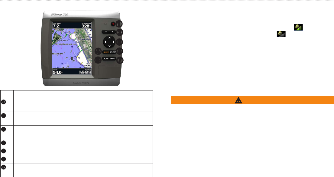
• Press from any screen to return to the Home screen.
• Press from any of the main screens to access advanced settings.
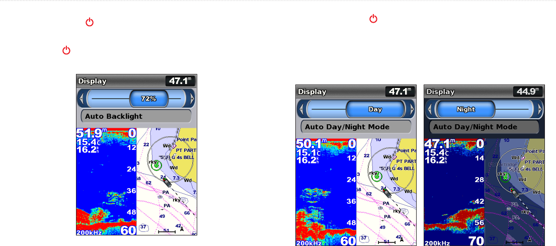
• Press and release the key to adjust the display settings.
In this manual, when you are instructed to select an item, small arrows (>)
appear in the text. They indicate that you should highlight a series of items on
the screen using the , and press the key after each item. For
example, if you see “select > ,” you should highlight
, and press . Then highlight , and press
again.
• Turning the Unit On or Off: page 2.
• Acquiring GPS Satellite Signals: page 5.
• Inserting and Removing SD Cards: page 6.
• Restoring the Original Factory Settings: page 6.
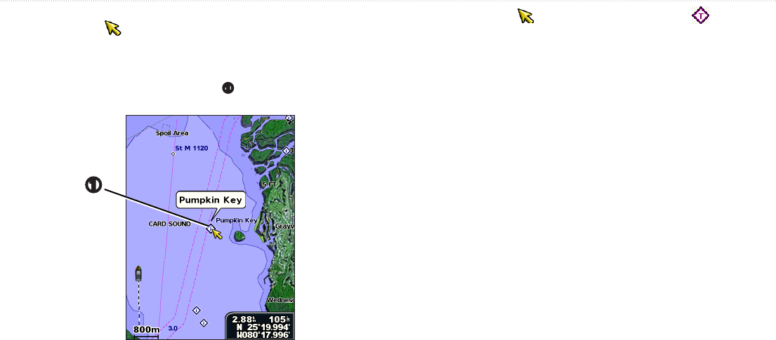
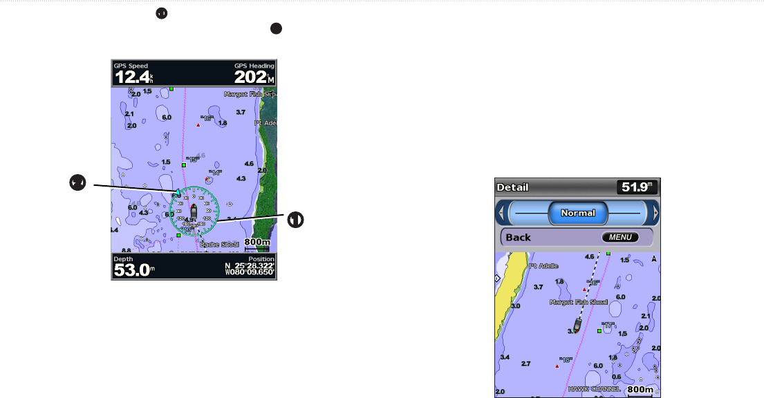
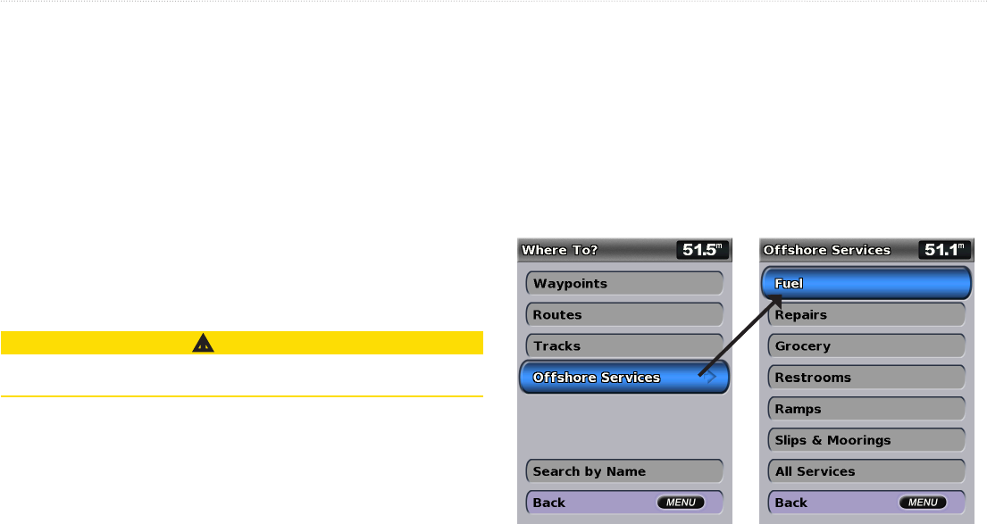
• Using the Navigation Chart: page 8.
• Changing the Navigation Chart Settings: page 11.
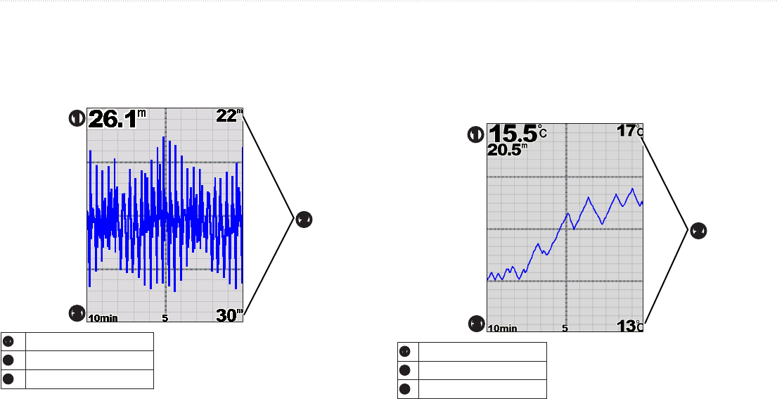
—zoom in to a section of the full screen. The zoom is off, or set to
by default. Four options are available:
• —turns zooming off.
• —twice the magnication.
• —four times the magnication.
• —set the depth range of the magnied area manually. Select
and then use the > to set the depth range of the
magnied area. Select and then use the > to increase
or decrease the magnication of the magnied area.
• —locks the zoom window to the bottom.
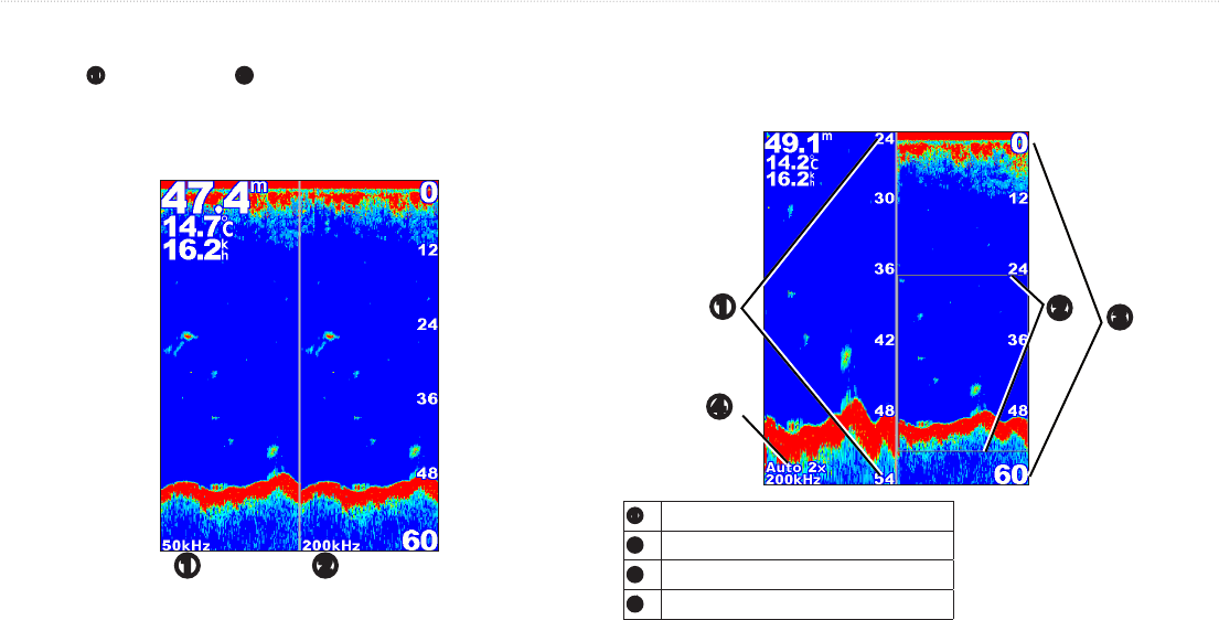
• —displays the Split Zoom screen (page 55).
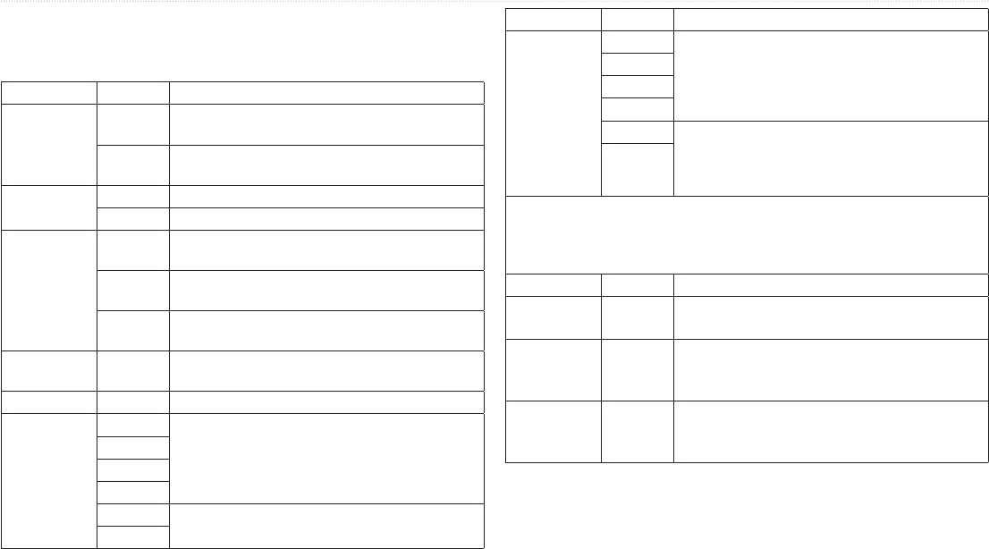
(available only when is set to )—reduces on-screen
visual clutter (usually from electrical sources) on the screen. Select the top
slider bar to manually adjust the value of noise rejection. Manually adjusting
the amount of noise that is rejected helps ne-tune the sonar to show the most
detail with the least noise.
When is set to (and is set to ), you can
individually adjust noise rejection for each frequency.
Digital Selective Calling (DSC)
GPSMAP 400/500 Series Owner’s Manual 59
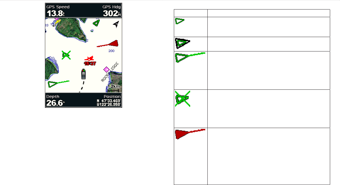
The following table indicates the features that are available when you connect your chartplotter to a VHF radio over a NMEA 0183 network or a NMEA 2000
network.
The chartplotter can transfer your GPS position to your radio� If your radio
is capable, GPS position information is transmitted with DSC calls�
The chartplotter can receive DSC distress and position information from
the radio�
The chartplotter can track the positions of vessels sending position
reports�
Quickly set up and send individual routine call details to your Garmin VHF
radio�
When you initiate a man-overboard distress call from your radio, the
chartplotter displays the man-overboard screen and prompts you to
navigate to the man-overboard point�
When you initiate a man-overboard distress call from your chartplotter, the
radio displays the Distress Call page to initiate a man-overboard distress
call�
1. Select > .
2. Select to toggle it on or off.
Digital Selective Calling (DSC)
60 GPSMAP 400/500 Series Owner’s Manual
You can make calls to a DSC contact from the chartplotter. See
page 62 for information on making an individual routine call.
1. While viewing a chart, press > > >
> .
2. Use the to enter the Maritime Mobile Service Identity (MMSI)
number of the vessel, and press .
3. Use the on-screen keyboard to enter the name of the vessel, and select
.
The DSC list is a log of the most-recent DSC calls and other DSC contacts you
have entered. The DSC list can contain up to 100 entries. The DSC list shows
the most-recent call from a boat. If a second call is received from the same
boat, it replaces the rst call in the call list.
From a chart screen, press > > > .
If your Garmin chartplotter and VHF radio are connected via NMEA 0183
or NMEA 2000, your chartplotter alerts you when your VHF radio receives a
DSC distress call. If position information was sent with the distress call, that
information is also available and recorded with the call.
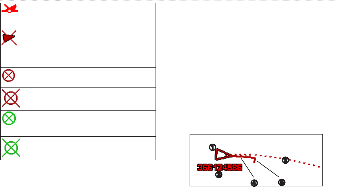
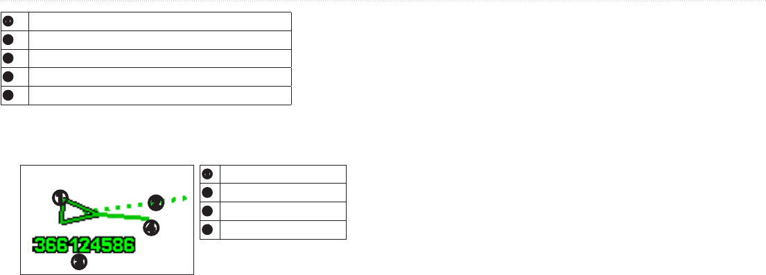
The symbol designates a distress call in the DSC List and marks the
position of a vessel on the Navigation chart at the time the DSC distress call
was sent.
1. Select to view details about the call.
2. Complete one of the following:
• Select to set up an individual routine call with
the radio to call the vessel in distress (page 62). This option is only
available if you are using a Garmin NMEA 2000-compatible VHF
radio.
• Select to edit the vessel name and add a comment. If your radio is
tracking the position of the vessel, select to show or hide the trail
line for the vessel, and select to change the line color. Select
to delete the call report. Select to set a
waypoint at the position sent with the distress call.
Gebruikershandleiding.com neemt misbruik van zijn services uitermate serieus. U kunt hieronder aangeven waarom deze vraag ongepast is. Wij controleren de vraag en zonodig wordt deze verwijderd.
Product:
Spelregels forum
Om tot zinvolle vragen te komen hanteren wij de volgende spelregels:
lees eerst de handleiding door;
controleer of uw vraag al eerder door iemand anders is gesteld;
probeer uw vraag zo duidelijk mogelijk te stellen;
heeft u een probleem en al geprobeerd om dit op te lossen, vermeld dit erbij aub;
heeft u een oplossing gekregen van een bezoeker dan horen wij dat graag in dit forum;
wilt u een reactie geven op een vraag of antwoord, gebruik dan niet dit formulier maar klik op de knop 'reageer op deze vraag';
uw vraag wordt direct op de website gezet; vermijd daarom persoonlijke gegevens in te vullen;
Belangrijk! Als er een antwoord wordt gegeven op uw vraag, dan is het voor de gever van het antwoord nuttig om te weten als u er wel (of niet) mee geholpen bent! Wij vragen u dus ook te reageren op een antwoord.
Belangrijk! Antwoorden worden ook per e-mail naar abonnees gestuurd. Laat uw emailadres achter op deze site, zodat u op de hoogte blijft. U krijgt dan ook andere vragen en antwoorden te zien.
Abonneren
Abonneer u voor het ontvangen van emails voor uw Garmin GPSMAP 421s bij:
nieuwe vragen en antwoorden
nieuwe handleidingen
U ontvangt een email met instructies om u voor één of beide opties in te schrijven.
Ontvang uw handleiding per email
Vul uw emailadres in en ontvang de handleiding van Garmin GPSMAP 421s in de taal/talen: Engels als bijlage per email.
De handleiding is 4,12 mb groot.
U ontvangt de handleiding per email binnen enkele minuten. Als u geen email heeft ontvangen, dan heeft u waarschijnlijk een verkeerd emailadres ingevuld of is uw mailbox te vol. Daarnaast kan het zijn dat uw internetprovider een maximum heeft aan de grootte per email. Omdat hier een handleiding wordt meegestuurd, kan het voorkomen dat de email groter is dan toegestaan bij uw provider.
Uw handleiding is per email verstuurd. Controleer uw email
Als u niet binnen een kwartier uw email met handleiding ontvangen heeft, kan het zijn dat u een verkeerd emailadres heeft ingevuld of dat uw emailprovider een maximum grootte per email heeft ingesteld die kleiner is dan de grootte van de handleiding.
Er is een email naar u verstuurd om uw inschrijving definitief te maken.
Controleer uw email en volg de aanwijzingen op om uw inschrijving definitief te maken
U heeft geen emailadres opgegeven
Als u de handleiding per email wilt ontvangen, vul dan een geldig emailadres in.
Uw vraag is op deze pagina toegevoegd
Wilt u een email ontvangen bij een antwoord en/of nieuwe vragen? Vul dan hier uw emailadres in.