Except as expressly provided herein, no part of this manual may be reproduced, copied, transmitted, disseminated, downloaded or stored in any stor-
age medium, for any purpose without the express prior written consent of Garmin. Garmin hereby grants permission to download a single copy of this
manual and of any revision to this manual onto a hard drive or other electronic storage medium to be viewed and to print one copy of this manual or of
any revision hereto, provided that such electronic or printed copy of this manual or revision must contain the complete text of this copyright notice and
provided further that any unauthorized commercial distribution of this manual or any revision hereto is strictly prohibited.
Information in this document is subject to change without notice. Garmin reserves the right to change or improve its products and to make changes in
the content without obligation to notify any person or organization of such changes or improvements.
Web site address: www.garmin.com
GARMIN
®
, Autolocate
®
, GPSMAP
®
, MapSource
®
, BlueChart
®
and TracBack
®
are registered trademarks of Garmin Ltd. or its subsidiaries and may not be
used without the express permission of Garmin. Fishing Hots Spots
®
is a registered trademark of Fishing Hots Spots, Inc.
June 2004 Part Number 190-00371-00 Rev. A Printed in Taiwan
• NMEA In/NMEA Out – supports the input/output of standard NMEA 0183 data, DSC, and sonar
NMEA input support for the DPT, MTW and VHW sentences. You may also adjust the NMEA
output.
• None – provides no interfacing capabilities.
Port 2:
• NMEA In/NMEA Out – supports the input/output of standard NMEA 0183 data, DSC, and sonar
NMEA input support for the DPT, MTW and VHW sentences. You may also adjust the NMEA
output.
• None – provides no interfacing capabilities.
You may also adjust the NMEA output to enable/disable certain sentences and adjust the number of
Lat/Lon output precision digits. You must have one of the ports set to NMEA In/NMEA Out to use this
option. Settings affects both Port 1 and Port 2 NMEA outputs.
NMEA Interface
If you are going to interface the GPSMAP 3006C/3010C with another piece of equipment (such as a
radio or autopilot), the unit needs to be set to input/output NMEA data. More information on wiring and
NMEA data may be found in the Installation Manual.
To activate the NMEA data:
1. On either Port fi eld and press ENTER.
2. Select ‘NMEA In/NMEA Out’ and press ENTER.
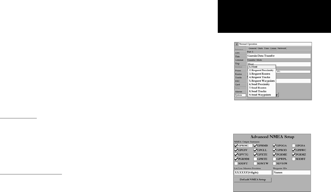
Advanced NMEA Output Setup
The GPSMAP 3006C/3010C NMEA data transmission can be customized to change the precision of
the Lat/Lon minutes, set up the waypoint IDs, and keep the output rate at two seconds. If the unit is set
up to output all of the available NMEA sentences, the output rate may exceed two seconds. The ‘Advanced
NMEA Output Setup’ page allows you to turn on/off the GPS status (GSA. GSV), Waypoint/Route (WPL,
RTE), and the Garmin Proprietary sentences. Check any other equipment’s owners manual to see what
sentences are required to be enabled for functionality.
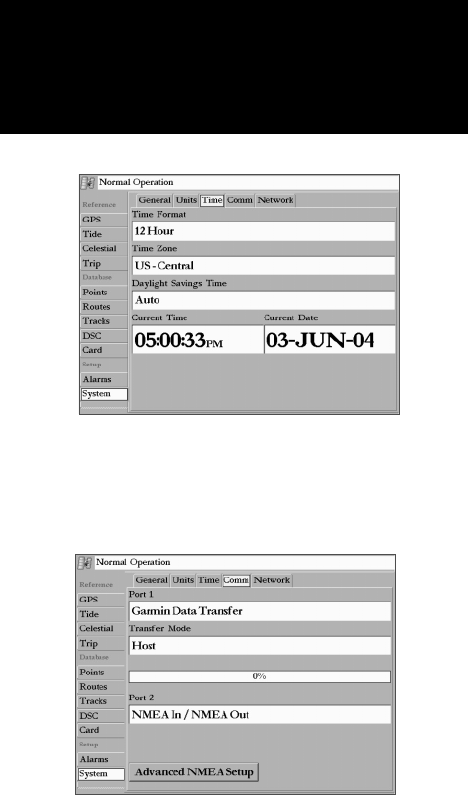
When transferring data between two
Garmin units, be sure to always set one
to ‘Host’ and use the other unit to either
Send or Request the desired data.
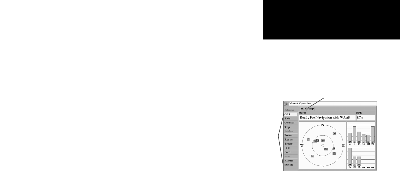
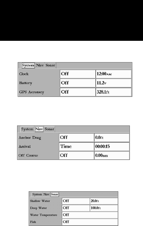
Main Menu: System Tab
Advanced NMEA
Setup Page
74
Getting Started
Main Page Sequence
74
Reference
Lat/Lon Minutes Precision allows you to adjust the number of digits to the right of the decimal point
for transmission of NMEA Output, either 2, 3 or 4 digits. The Waypoint ID setting lets you choose to
output the waypoint identifi ers as names or numbers.
To set up the Advanced NMEA page:
1. Highlight ‘Advanced NMEA Setup’ button and press ENTER.
2. To change enable/disable NMEA Output Sentences, highlight the desired sentence and press ENTER to
check/uncheck. Only checked sentences will output.
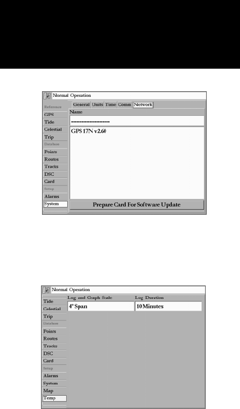
Network Submenu Tab— display on/off selections for the devices currently connected to the MFD
and Garmin Marine Network. The ‘Prepare Card For Software Update’ button is to be used for future
software releases only. Check the Garmin web site for future updates and announcements.
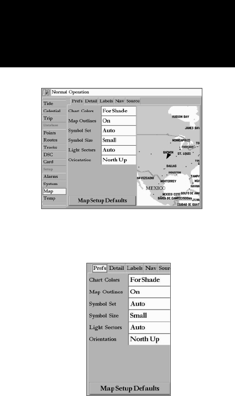
Map Tab— contains setup options for the Map Page. See page 30.
Temp ( Temperature) Tab— displays the water temperature log (if equipped with a temperature
transducer/sensor). The chart reads from right to left, so that the most recent temperature measured is
displayed on the far right side of the chart. The dotted lines within the chart indicate intervals in the
temperature scale and the duration of time. You must be receiving NMEA Sonar temperature data or using
a Garmin Sonar Module for the Temperature Graph to display.
The following settings are available:
• Temperature Scale – sets the temperature range (in degrees) for displaying the log. Select ‘Auto’
to have the unit automatically determine the best range, or select a span of 2, 4, 6, 8 or 10 degrees.
Use the ‘Reset’ button in ‘Auto’ mode to reset the automatic range.
• Time Duration – sets how fast or slow the temperature log scrolls; the shorter the time duration,
the faster the temperature log scroll. Select a duration from 1 minute to 2.5 hours.
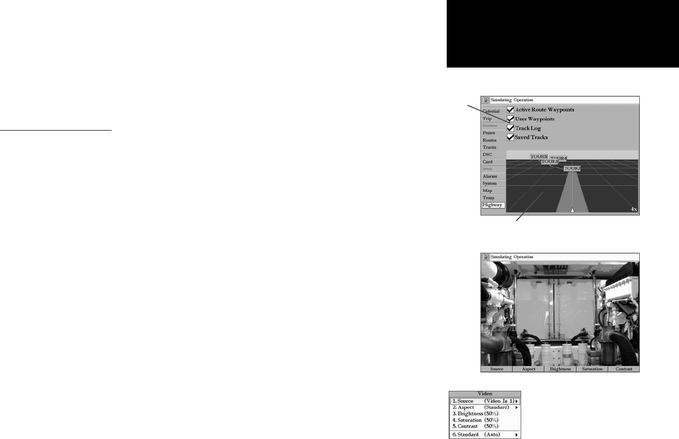
Highway Tab— contains setup options for the Highway Page. See page 35.
Main Menu—Temp Tab
Main Menu: System/
Temp Tabs
Main Menu—System Tab
(Network Submenu)
75
Getting Started
Main Page Sequence
75
The chart below gives an approximate UTC (Universal Time Coordinate) time offset for the various
longitudinal zones. Check with local charts for more detailed information. If you are in daylight savings
time, add one hour to the offset.
Longitudinal ZoneOffset
W180.0º to W172.5º -12
W172.5º to W157.5º -11
W157.5º to W142.5º -10
W142.5º to W127.5º -9
W127.5º to W112.5º -8
W112.5º to W097.5º -7
W097.5º to W082.5º -6
W082.5º to W067.5º -5
W067.5º to W052.5º -4
W052.5º to W037.5º -3
W037.5º to W022.5º -2
W022.5º to W007.5º -1
W007.5º to E007.5º 0
E007.5º to E022.5º +1
E022.5º to E037.5º +2
E037.5º to E052.5º +3
E052.5º to E067.5º +4
E067.5º to E082.5º +5
E082.5º to E097.5º +6
E097.5º to E112.5º +7
E112.5º to E127.5º +8
E127.5º to E142.5º +9
E142.5º to E157.5º +10
E157.5º to E172.5º +11
E172.5º to E180.0º +12
A simple way to determine your local time offset is
how many hours you are behind or ahead of UTC
(also called ‘Greenwich’ or ‘zulu’ time).
Example: EST (Eastern Standard Time) is 5 hours
behind UTC, so your offset would be -5. Adding one
hour for daylight savings would make EDT (Eastern
Daylight Time) - 4. Subtract an hour for each time
zone as you travel west.
Offsets for Continental U.S. would be:
EST
-5EDT-4
CST-6CDT-5
MST-7MDT-6
PST-8PDT-7
+
Appendix A
Time Offsets
76
Getting Started
Main Page Sequence
76
The GPSMAP 3006C/3010C uses an on-screen pop-up message system to alert you to unit operating
characteristics. Press the QUIT key to acknowledge and return to the page you were viewing.
Accuracy Alarm— The GPS accuracy has fallen outside of user-set value.
Alarm Clock— The alarm clock has sounded.
Anchor Drag Alarm— You have drifted out of the specifi ed distance range.
Approaching <Waypoint>— You are a specifi ed alarm distance from a destination waypoint.
Arrival At <Waypoint>— You have arrived at the destination waypoint.
Battery Alarm— Specifi ed amount of input voltage has been detected.
Can’t Read User Card— Error reading card. Remove and reinsert. Contact your dealer or Garmin Customer Service (pg. 86) if the problem persists.
Can’t Read Voltages That High, Limited To Top Of Range— Voltage range must be between 10.0 and 35.0 volts for the GPSMAP 3006C/3010C.
Can’t Read Voltages That Low, Limited To Bottom Of Range — Voltage range must be between 10.0 and 35.0 volts for the GPSMAP 3006C/3010C.
Can’t Unlock Maps— Data on data card is not unlocked for the unit. Contact your dealer or Garmin Customer Service (pg. 86).
Can’t Write User Card— Error reading card. Remove and reinsert. Contact your dealer or Garmin Customer Service (pg. 86) if the problem persists.
Database Error— Internal problem with the unit. Contact your dealer or Garmin Customer Service (pg. 86) to have the unit serviced.
Deep Water Alarm— Specifi ed deep water alarm depth has been detected below transducer.
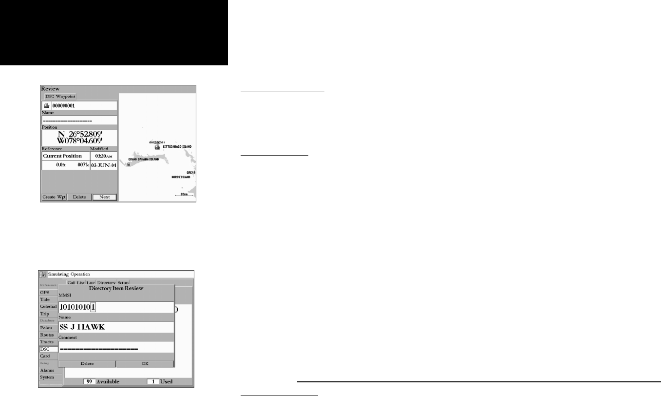
Directory Item With This MMSI Already Exists— MMSI number already in DSC directory. Use a different number..
Directory Memory is Full Can’t Create Entry— DSC directory has reached maximum of 1000 contacts. Delete unneeded contacts to add new ones.
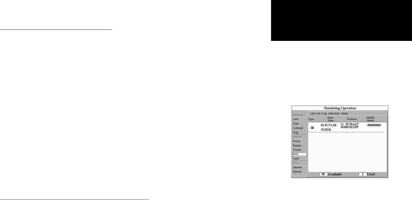
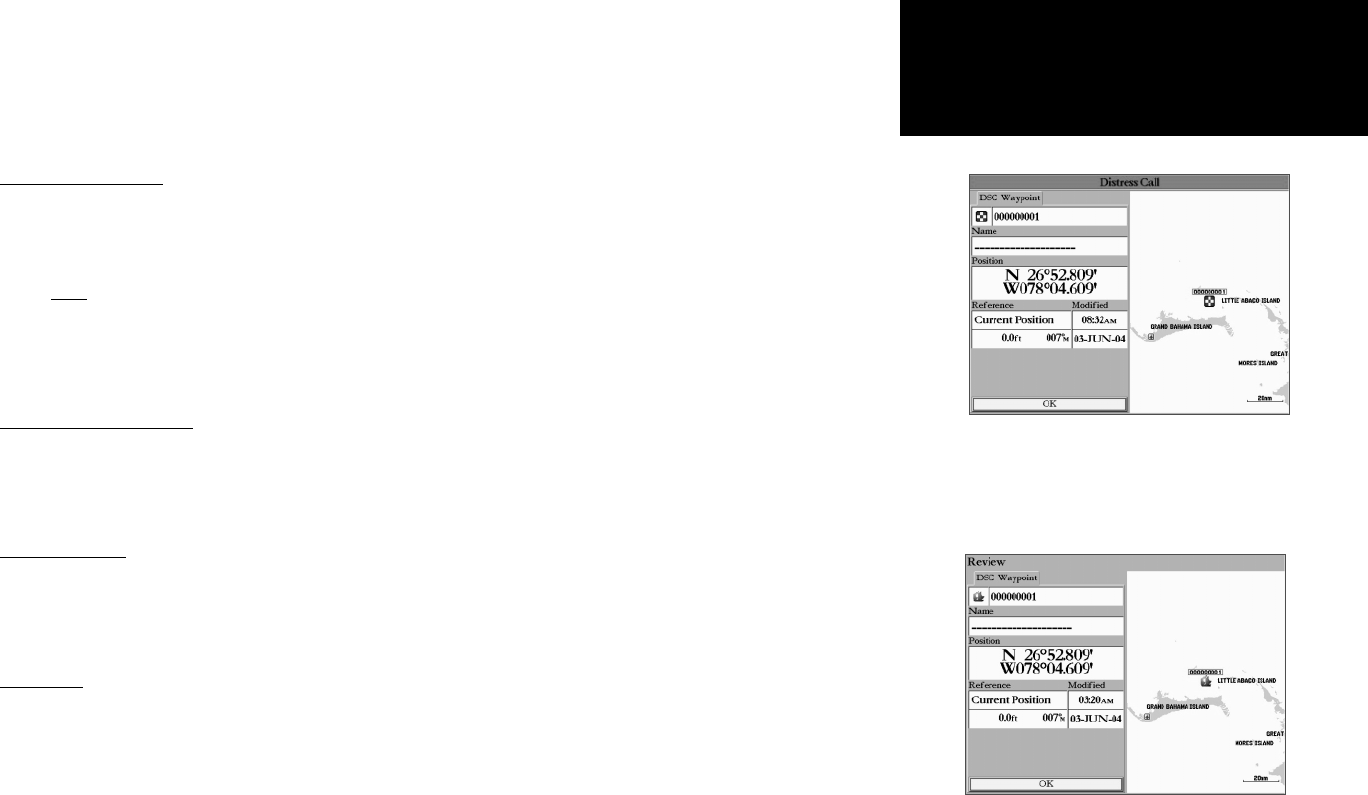
Distress Call— DSC distress call has been received. Take appropriate action.
Lost Remote GPS Connection— Problem with GPS antenna wiring. Check connections.
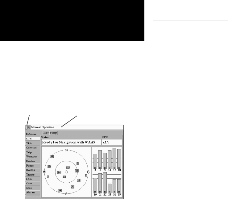
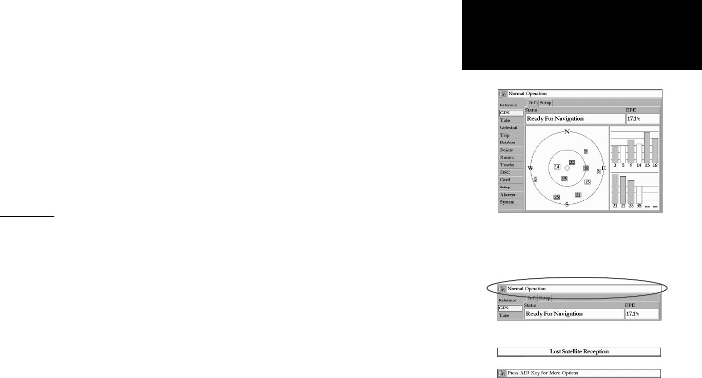
Lost Satellite Reception— The unit has lost satellite signals. Check antenna connections or try moving to a location with a clear view of the sky.
No Proximity Waypoints/Routes/Tracks/User Waypoints Found— Attempted to transfer user data from data empty data card. Make sure there is data to trans-
fer on data card.
Appendix B
Messages
77
Getting Started
Main Page Sequence
77
Messages
Appendix B
Not All Maps Fit, Some Maps will not be drawn— Maximum number of individual maps on data
card(s) has been exceeded.
Off Course Alarm— You have exceeded the specifi ed off-course distance.
Proximity Alarm Memory is Full— You have used all available proximity waypoints.
Proximity Alarm: <Waypoint>— You have entered the alarm radius for the proximity waypoint indicated.
Proximity Overlaps Another Proximity Waypoint—The alarm radius specifi ed overlaps the area specifi ed for another proximity waypoint. Adjust the distance.
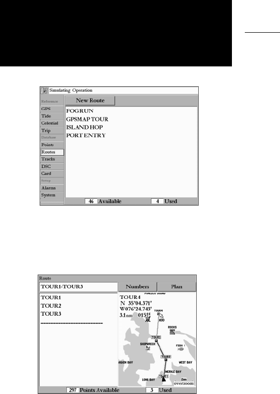
Route Already Exists: <route name>— You have entered a route name that already exists in memory. Modify the route name or delete the previous route name.
Route Is Full— You have attempted to add more than 300 points to a route. Reduce the number of points or create a second route.
Route Memory Is Full, Can’t Create Route— Maximum amount of 300 routes is already in the unit’s memory and no additional routes can be added until
existing ones are removed.
Route Truncated— An uploaded route from another device has more than 300 points. Reduce the number of points.
Shallow Water Alarm— Specifi ed shallow water alarm depth has been detected below transducer.
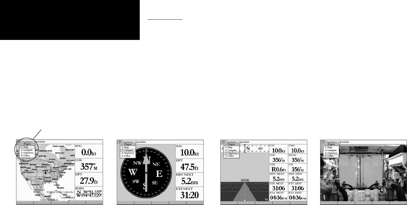
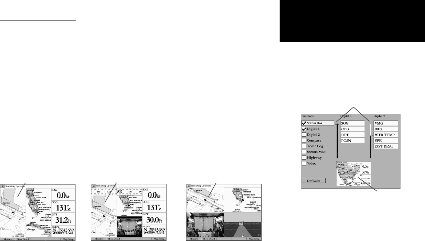
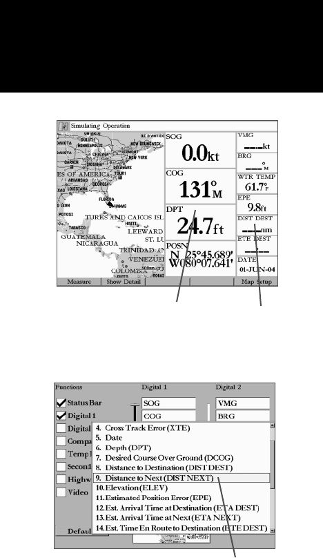
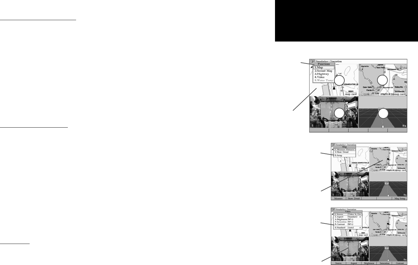
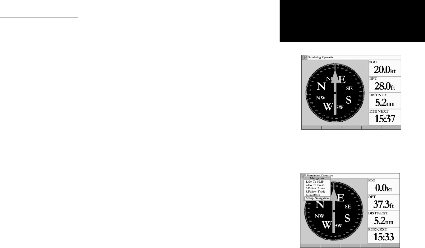
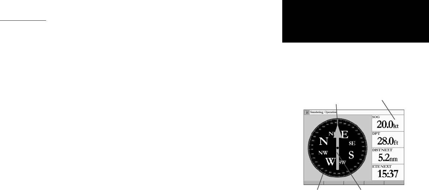
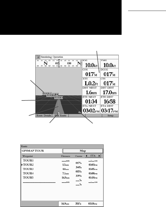
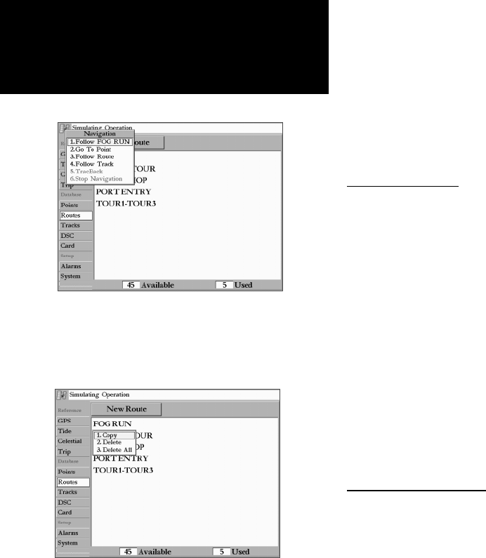
Simulating Operation— The unit is in Simulator (practice) Mode. Do not use for normal navigation!
Track Already Exists: <track name>— You have entered a saved track name that already exists in memory. Modify the track name or delete the previous track
name.
Track Memory Is Full, Can’t Create Track— Track log memory is full. No additional track log data can be stored without deleting old data to create memory
space.
Track Truncated— A complete uploaded track does not fi t into memory. The oldest track log points were deleted to make space for the most recent data.
Transfer Complete— The unit has fi nished uploading/downloading information to the connected device.
User Card Not Found— Attempted to transfer user data without a data card containing user data being present in Slot 1.
Water Temperature Alarm— Sonar has reported a temperature above, below, inside or outside the specifi ed value.
Waypoint Already Exists: <Waypoint>— You have entered a waypoint name that already exists in memory. Modify the waypoint name or delete the previous
waypoint name.
Waypoint Memory Is Full Can’t Create Waypoint— You have used all 4000 waypoints available. Delete unwanted waypoints to make space for new entries.
78
Getting Started
Main Page Sequence
78
Adindan Adindan- Ethiopia, Mali, Senegal, Sudan
Afgooye Afgooye- Somalia
AIN EL ABD ‘70 AIN EL ANBD 1970- Bahrain Island,
Saudi Arabia
Anna 1 Ast ‘65 Anna 1 Astro ‘65- Cocos I.
ARC 1950 ARC 1950- Botswana, Lesotho, Malawi,
Swaziland, Zaire, Zambia, Zimbabwe
ARC 1960 Kenya, Tanzania
Ascnsn Isld ‘58 Ascension Island ‘58- Ascension Island
Astro B4 Sorol Sorol Atoll- Tern Island
Astro Bcn “E” Astro Beacon “E”- Iwo Jima
Astro Dos 71/4 Astro Dos 71/4- St. Helena
Astr Stn ‘52 Astronomic Stn ‘52- Marcus Island
Aus Geod ‘66 Australian Geod ‘66- Australia, Tasmania
Island
Aus Geod ‘84 Australian Geod ‘84- Australia, Tasmania
* Subject to accuracy degradation to 100m 2DRMS under the U.S. DOD-imposed Selective Availability Program.
Power
Source: 10-35v DC
Usage: 25 watts max. at 10v DC
Fuse: AGC-5 - 5.0 Amp
83
Getting Started
Main Page Sequence
83
Appendix F
Installing/Removing Data Cards
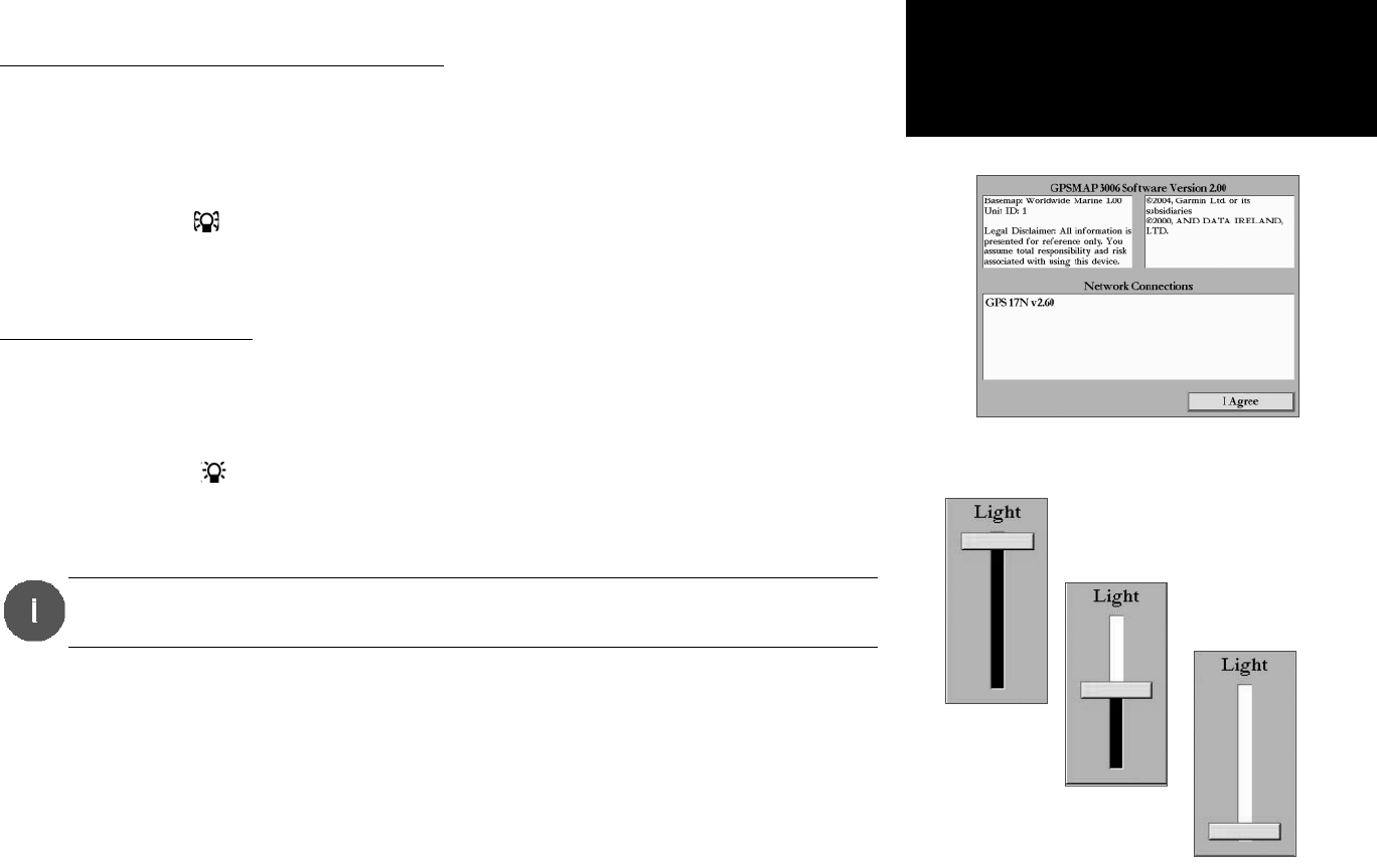
Once the data card has
been read, a sum-
mary screen appears.
Press ENTER/MARK to
acknowledge.
Installing and Removing Data cards
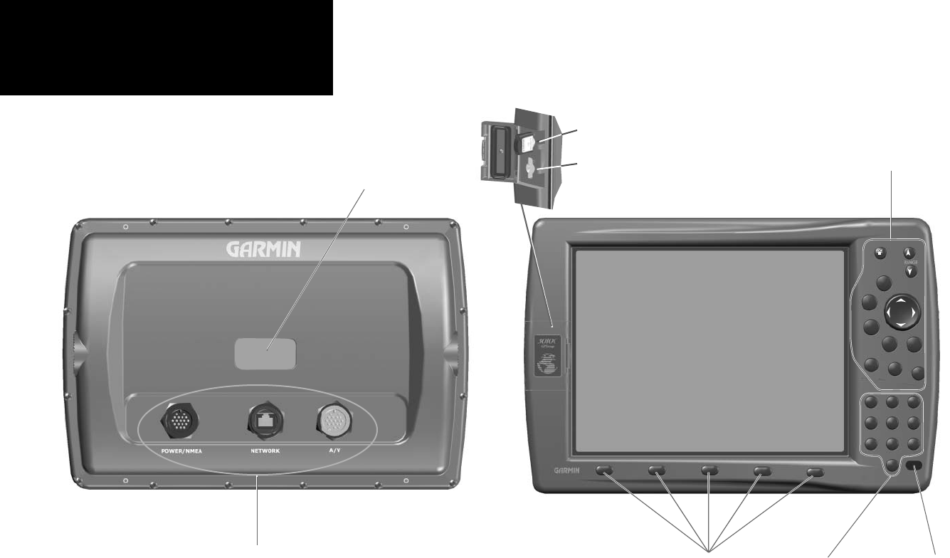
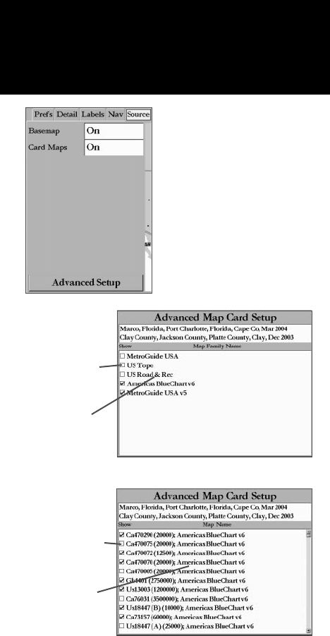
The GPSMAP 3006C/3010C uses optional Garmin marine BlueChart and MapSource data cards to dis-
play digital charts and maps on-screen. Data cards are installed in the card slot located at the bottom right
of the unit. Data cards may be installed or removed at any time, whether the unit is on or off.
To install a data card:
1. Open the card door by pressing the locking tab on the door towards the outside (left) of the unit and lifting
the door open from right to left.
2. Insert the card into the slot, with the label facing to the right and the handle towards you.
3. Firmly push the card into the unit. It in not necessary to force the card and about 1/2” is still exposed when
it is properly inserted. If the unit is on, a confi rmation tone sounds and a message displays on the screen
noting the card details when the card has been properly installed and accepted.
4. Close the cover until it locks.
If you insert a data card and get a ‘card format not recognized’ message, try removing the card and
reinserting it. If the card is still not recognized, contact the Garmin or your Garmin dealer for assistance.
Data cards are not waterproof, should not be exposed to moisture or excessive static charges, and should
be stored in the case supplied with the card.
To remove a data card:
1. Open the card door by pressing the locking tab on the door towards the outside (left) of the unit and lifting
the door open from right to left.
2. Grasp the card handle and pull out fi rmly.
3. If the unit is on, a confi rmation tone sounds when the data card has been removed.
The fi rst time you insert a
data card, the unit takes
a few seconds to read the
card.
84
Getting Started
Main Page Sequence
84
Appendix G
Regulatory Information
FCC Compliance
The GPSMAP 3006C/3010C complies with Part 15 of the FCC interference limits for Class B digital
devices FOR HOME OR OFFICE USE. These limits are designed to provide more reasonable protection
against harmful interference in a residential installation, and are more stringent than “outdoor” require-
ments.
Operation of this device is subject to the following conditions: (1) This device may not cause harmful
interference, and (2) this device must accept any interference received, including interference that may
cause undesired operation.
This equipment generates, uses and can radiate radio frequency energy and, if not installed and used in
accordance with the instructions, may cause harmful interference to radio communications. However,
there is no guarantee that interference will not occur in a particular installation. If this equipment does
cause harmful interference to radio or television reception, which can be determined by turning the equip-
ment off and on, the user is encouraged to try to correct the interference by one of the following measures:
• Reorient or relocate the receiving antenna.
• Increase the separation between the equipment and the receiver.
• Connect the equipment into an outlet on a circuit different from that to which the receiver is con-
nected.
• Consult the dealer or an experienced radio/TV technician for help.
The GPSMAP 3006C/3010C does not contain any user-serviceable parts. Repairs should only be made
by an authorized Garmin service center. Unauthorized repairs or modifi cations could result in permanent
damage to the equipment, and void your warranty and your authority to operate this device under Part 15
regulations.
85
Getting Started
Main Page Sequence
85
Appendix G
Software License Agreement
Software License Agreement
BY USING THE GPSMAP 3006C/3010C, YOU AGREE TO BE BOUND BY THE TERMS AND CONDI-
TIONS OF THE FOLLOWING SOFTWARE LICENSE AGREEMENT. PLEASE READ THIS AGREEMENT
CAREFULLY.
Garmin grants you a limited license to use the software embedded in this device (the “Software”) in
binary executable form in the normal operation of the product. Title, ownership rights and intellectual
property rights in and to the Software remain in Garmin.
You acknowledge that the Software is the property of Garmin and is protected under the United States
of America copyright laws and international copyright treaties. You further acknowledge that the struc-
ture, organization and code of the Software are valuable trade secrets of Garmin and that the Software in
source code form remains a valuable trade secret of Garmin. You agree not to decompile, disassemble,
modify, reverse assemble, reverse engineer or reduce to human readable form the Software or any part
thereof or create any derivative works based on the Software. You agree not to export or re-export the
Software to any country in violation of the export control laws of the United States of America.
86
Getting Started
Main Page Sequence
86
Appendix G
Limited Warranty
LIMITEDWARRANTY
This Garmin product is warranted to be free from defects in materials or workmanship for one year
from the date of purchase. Within this period, Garmin will at its sole option, repair or replace any compo-
nents that fail in normal use. Such repairs or replacement will be made at no charge to the customer for
parts or labor, provided that the customer shall be responsible for any transportation cost. This warranty
does not cover failures due to abuse, misuse, accident or unauthorized alteration or repairs.
THE WARRANTIES AND REMEDIES CONTAINED HEREIN ARE EXCLUSIVE AND IN LIEU OF ALL OTHER WARRANTIES EXPRESS OR IMPLIED OR
STATUTORY, INCLUDING ANY LIABILITY ARISING UNDER ANY WARRANTY OF MERCHANTABILITY OR FITNESS FOR A PARTICULAR PURPOSE, STATU-
TORY OR OTHERWISE. THIS WARRANTY GIVES YOU SPECIFIC LEGAL RIGHTS, WHICH MAY VARY FROM STATE TO STATE.
IN NO EVENT SHALL GARMIN BE LIABLE FOR ANY INCIDENTAL, SPECIAL, INDIRECT OR CONSEQUENTIAL DAMAGES, WHETHER RESULTING
FROM THE USE, MISUSE, OR INABILITY TO USE THIS PRODUCT OR FROM DEFECTS IN THE PRODUCT. Some states do not allow the exclusion of inci-
dental or consequential damages, so the above limitations may not apply to you.
Garmin retains the exclusive right to repair or replace the unit or software or offer a full refund of the purchase price at its sole discretion. SUCH REMEDY
SHALL BE YOUR SOLE AND EXCLUSIVE REMEDY FOR ANY BREACH OF WARRANTY.
To obtain warranty service, contact your local Garmin authorized dealer. Or call Garmin Customer Service at one of the numbers shown below, for shipping
instructions and an RMA tracking number. The unit should be securely packed with the tracking number clearly written on the outside of the package. The unit
should then be sent, freight charges prepaid, to any Garmin warranty service station. A copy of the original sales receipt is required as the proof of purchase for
warranty repairs.
Products sold through online auctions are not eligible for rebates or other special offers from Garmin. Online auction confi rmations are not accepted for war-
ranty verifi cation. To obtain warranty service, an original or copy of the sales receipt from the original retailer is required. Garmin will not replace missing compo-
nents from any package purchased through an online auction.
Garmin International, Inc. Garmin (Europe) Ltd.
1200 East 151st Street Unit 4, The Quadrangle, Abbey Park Industrial Estate
Gebruikershandleiding.com neemt misbruik van zijn services uitermate serieus. U kunt hieronder aangeven waarom deze vraag ongepast is. Wij controleren de vraag en zonodig wordt deze verwijderd.
Product:
Spelregels forum
Om tot zinvolle vragen te komen hanteren wij de volgende spelregels:
lees eerst de handleiding door;
controleer of uw vraag al eerder door iemand anders is gesteld;
probeer uw vraag zo duidelijk mogelijk te stellen;
heeft u een probleem en al geprobeerd om dit op te lossen, vermeld dit erbij aub;
heeft u een oplossing gekregen van een bezoeker dan horen wij dat graag in dit forum;
wilt u een reactie geven op een vraag of antwoord, gebruik dan niet dit formulier maar klik op de knop 'reageer op deze vraag';
uw vraag wordt direct op de website gezet; vermijd daarom persoonlijke gegevens in te vullen;
Belangrijk! Als er een antwoord wordt gegeven op uw vraag, dan is het voor de gever van het antwoord nuttig om te weten als u er wel (of niet) mee geholpen bent! Wij vragen u dus ook te reageren op een antwoord.
Belangrijk! Antwoorden worden ook per e-mail naar abonnees gestuurd. Laat uw emailadres achter op deze site, zodat u op de hoogte blijft. U krijgt dan ook andere vragen en antwoorden te zien.
Abonneren
Abonneer u voor het ontvangen van emails voor uw Garmin GPSMAP 3010C bij:
nieuwe vragen en antwoorden
nieuwe handleidingen
U ontvangt een email met instructies om u voor één of beide opties in te schrijven.
Ontvang uw handleiding per email
Vul uw emailadres in en ontvang de handleiding van Garmin GPSMAP 3010C in de taal/talen: Engels als bijlage per email.
De handleiding is 3,26 mb groot.
U ontvangt de handleiding per email binnen enkele minuten. Als u geen email heeft ontvangen, dan heeft u waarschijnlijk een verkeerd emailadres ingevuld of is uw mailbox te vol. Daarnaast kan het zijn dat uw internetprovider een maximum heeft aan de grootte per email. Omdat hier een handleiding wordt meegestuurd, kan het voorkomen dat de email groter is dan toegestaan bij uw provider.
Uw handleiding is per email verstuurd. Controleer uw email
Als u niet binnen een kwartier uw email met handleiding ontvangen heeft, kan het zijn dat u een verkeerd emailadres heeft ingevuld of dat uw emailprovider een maximum grootte per email heeft ingesteld die kleiner is dan de grootte van de handleiding.
Er is een email naar u verstuurd om uw inschrijving definitief te maken.
Controleer uw email en volg de aanwijzingen op om uw inschrijving definitief te maken
U heeft geen emailadres opgegeven
Als u de handleiding per email wilt ontvangen, vul dan een geldig emailadres in.
Uw vraag is op deze pagina toegevoegd
Wilt u een email ontvangen bij een antwoord en/of nieuwe vragen? Vul dan hier uw emailadres in.