For Your Safety
You must not operate the appliance if it is damaged.
When connecting electrical appliances in the proxi-
mity of the appliance, make sure that connecting
leads do not come into contact with hot cooking
surfaces!
As the user, you yourself are responsible for
maintenance and proper use in the household.
Only ever operate the appliance under supervision.
Do not operate the appliance without pots and pans
placed on it. Make sure that all the burner parts are
correctly fitted.
Caution: The appliance heats up during operation.
Keep children away.
Do not clean the appliance with a steam cleaning
apparatus or with water pressure - risk of short-
circuits!
Isolate the appliance from the mains during every
maintenance operation. To do this, remove the
mains plug or switch off the corresponding
household fuse. Close the gas supply.
Repairs must be carried out by authorised specia-
lists, thus ensuring electrical safety.
No warranty claims can be lodged for any damage
resulting from failure to observe these instructions.
Observe caution with oils and fats. They may
overheat and burn easily.
Foodstuffs that are prepared in fat and oil must only
be prepared under constant supervision!
Technical modifications reserved.
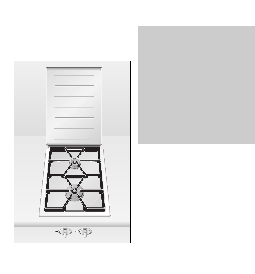
Operating for the First Time
Remove the packaging from the appliance and
dispose of it according to local regulations. Be
careful to remove all accessories from the
packaging. Keep packaging elements and plastic
bags away from children.
This appliance is labelled in accordance
with the European Directive 2002/96/EG
concerning used electrical and electronic
appliances (waste electrical and
electronic equipment – WEEE). The
guideline determines the framework for the return
and recycling of used appliances as applicable.
Check the appliance for transport damage before
installing it.
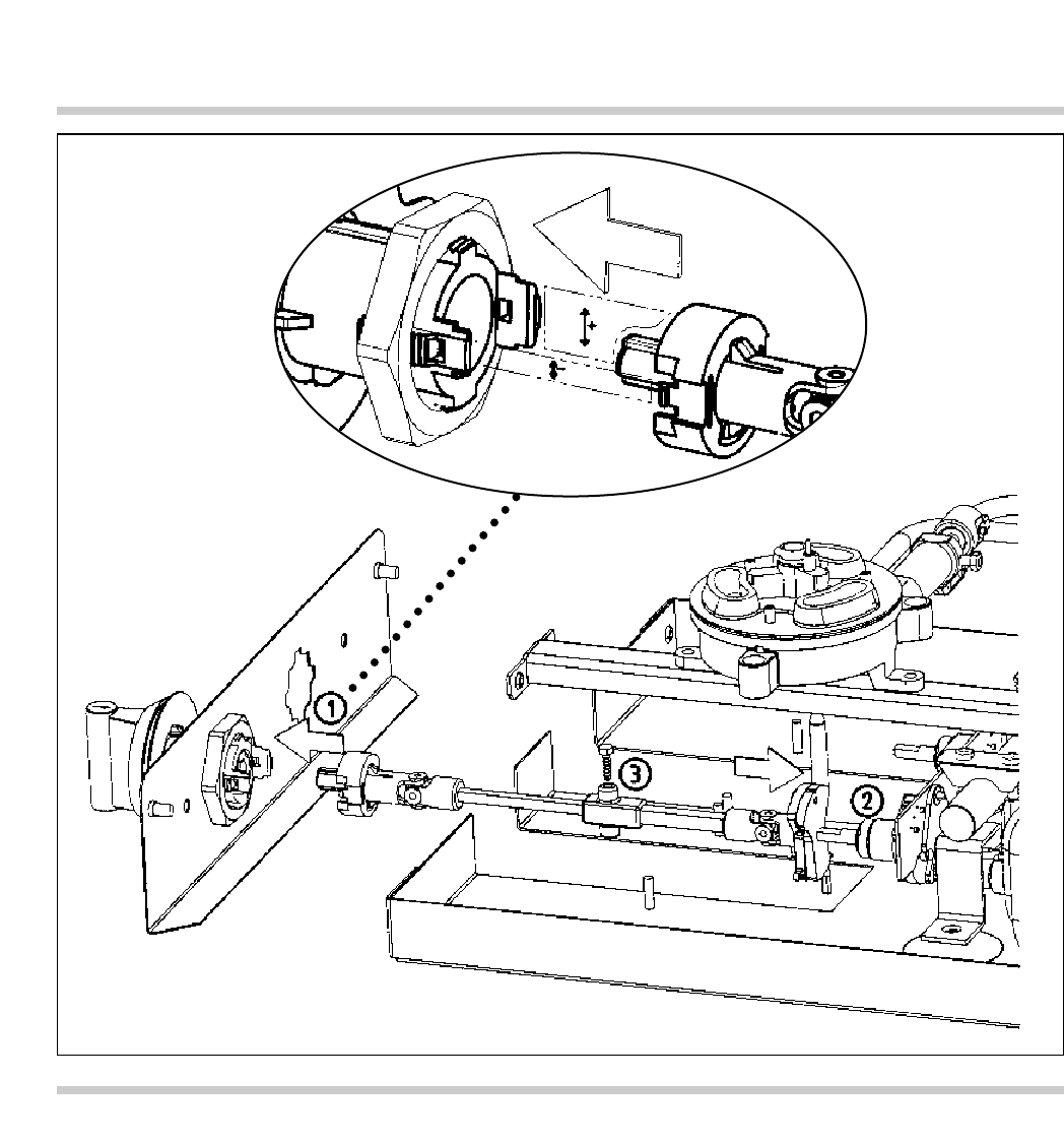
The appliance must be installed and connected by
an authorised specialist before operation. The
installation must conform with all current regulations
of the gas supply companies and the regional
construction regulations.
Turn all control knobs to the OFF position before
connecting the appliance to the power supply.
The serial number of the appliance can be found on
the quality control slip which is included with these
instructions. This quality control slip should be kept,
for guarantee reasons, together with your operating
and assembly instructions.
Read through these instructions attentively before
operating your appliance for the first time.
Thoroughly clean the appliance and accessories
before using them for the first time. This will
eliminate any 'newness’ smells and soiling (see
chapter “Cleaning and Care”).
3
1. Important Notes