641189
34
Verklein
Vergroot
Pagina terug
1/194
Pagina verder
OPERATOR'S MANUAL
www.furuno.com
SSB RADIOTELEPHONE
FS-1575
FS-2575
FS-5075
Model
The paper used in this manual
is elemental chlorine free.
・FURUNO Authorized Distributor/Dealer
9-52 Ashihara-cho,
Nishinomiya, 662-8580, JAPAN
A : JUL 2011
.
Printed in Japan
All rights reserved.
C : AUG . 03, 2012
Pub. No. OME-56770-C
*
00017516512
*
*
00017516512
*
(YOTA ) FS-1575/2575/5075
*
00017516512
*
*
00017516512
*
* 0 0 0 1 7 5 1 6 5 1 2 *
i
IMPORTANT NOTICES
General
This manual has been authored with simplified grammar, to meet the needs of international us-
ers.
The operator of this equipment must read and follow the descriptions in this manual. Wrong op-
eration or maintenance can cancel the warranty or cause injury.
Do not copy any part of this manual without written permission from FURUNO.
If this manual is lost or worn, contact your dealer about replacement.
The contents of this manual and equipment specifications can change without notice.
The example screens (or illustrations) shown in this manual can be different from the screens
you see on your display. The screens you see depend on your system configuration and equip-
ment settings.
Save this manual for future reference.
Any modification of the equipment (including software) by persons not authorized by FURUNO
will cancel the warranty.
All brand and product names are trademarks, registered trademarks or service marks of their
respective holders.
How to discard this product
Discard this product according to local regulations for the disposal of industrial waste. For disposal
in the USA, see the homepage of the Electronics Industries Alliance (http://www.eiae.org/) for the
correct method of disposal.
How to discard a used battery
Some FURUNO products have a battery(ies). To see if your product has a battery, see the chapter
on Maintenance. Follow the instructions below if a battery is used. Tape the + and - terminals of
battery before disposal to prevent fire, heat generation caused by short circuit.
In the European Union
The crossed-out trash can symbol indicates that all types of batteries
must not be discarded in standard trash, or at a trash site. Take the
used batteries to a battery collection site according to your national
legislation and the Batteries Directive 2006/66/EU.
In the USA
The Mobius loop symbol (three chasing arrows) indicates that Ni-Cd
and lead-acid rechargeable batteries must be recycled. Take the
used batteries to a battery collection site according to local laws.
In the other countries
There are no international standards for the battery recycle symbol. The number of symbols can
increase when the other countries make their own recycle symbols in the future.
Cd
Ni-Cd Pb
ii
SAFETY INSTRUCTIONS
Indicates a condition that can cause death or serious injury
if not avoided.
Indicates a condition that can cause minor or moderate
injury if not avoided.
Indicates a condition that will result in death or serious injury
if not avoided.
The user and installer must read the appropriate safety instructions before attempting to install
or operate the equipment.
DANGER
WARNING
CAUTION
Warning, Caution Prohibitive Action Mandatory Action
DANGER
WARNING
WARNING
Never touch the SSB antenna, antenna
coupler or lead-in insulator when the
SSB radiotelephone is transmitting.
High voltage which will cause death or
serious injury is present at the locations
shown in the illustration below when the
SSB radiotelephone is transmitting.
Antenna
Coupler
Antenna Wire
(High Voltage)
Indoor
Antenna
Wire
Lead-in
Insulator
(High
Voltage)
Do not open the equipment.
Only qualified personnel should work
inside the equipment.
Immediately turn off the power at
the switchboard if water leaks into
the equipment or something is
dropped into the equipment.
Continued use of the equipment can
cause fire or electrical shock. Contact
a FURUNO agent for service.
Do not disassemble or modify the
equipment.
Fire, electrical shock or serious injury
can result.
Immediately turn off the power at
the switchboard if the equipment is
emitting smoke or fire.
Continued use of the equipment can
cause fire or electrical shock. Contact
a FURUNO agent for service.
Do not place liquid-filled containers
on the top of the equipment.
Fire or electrical shock can result if a
liquid spills into the equipment.
Do not operate the equipment with
wet hands.
Electrical shock can result.
Turn off the power immediately if you
feel the equipment is behaving
abnormally.
Turn off the power at the switchboard if
the equipment becomes abnormally
warm or is emitting odd noises. Contact
a FURUNO dealer or agent for advice.
Make sure no rain or water splash
leaks into the equipment.
Fire or electrical shock can result if
water leaks in the equipment.
Use the proper fuse.
Use of the wrong fuse can cause fire or
electrical shock.
SAFETY INSTRUCTIONS
iii
The TFT LCD is constructed using the latest LCD techniques, and displays
99.99% of its pixels. The remaining 0.01% of the pixels may drop out or
blink, however this is not an indication of malfunction.
About the TFT LCD
Warning labels are attached to the equipment. Do not remove any label. If a label is missing or
damaged, contact a FURUNO agent or dealer about replacement.
Name: Warning Label 1
Type: 86-003-1011-3
Code No.: 100-236-233-10
WARNING
CAUTION
Do not operate the [DISTRESS]
key except in case of a
life-endangering situation on your
vessel.
Operating the [DISTRESS] key
transmits the distress alert.
Accidental transmission may prevent
search and rescue operations for
actual emergency. If the distress alert
is accidentally transmitted, contact
the nearest station to cancel the
alert.
If the distress alert is accidentally
transmitted, contact the nearest
coast station and inform them of the
accidental
transmission, providing the
following data:
a) Ship's name
b) Ship's call sign and DSC number
c) Position at time of transmission
d) Time of transmission
WARNING LABELS
Do not apply strong pressure to
the LCD, which is made of glass.
Injury can result if the LCD breaks.
Name: Warning Label
Type: 14-055-4202-1
Code No.: 100-245-221-10
Name: High Temp Warning Label
Type: 05-089-2142-0
Code No.: 100-301-620-10
iv
DISTRESS ALERT
How to send distress alert
Below is the procedure for transmitting a distress alert via radiotelephone. Transmit the distress
alert when a life-endangering situation occurs on your vessel.
1. Open the DISTRESS key cover then press the DISTRESS key for four seconds. The following
screen appears.
2. When the message "Sending DISTRESS ALERT." appears on the screen, release the DIS-
TRESS key. The audio alarm sounds for two seconds.
After the distress alert has been sent, the following screens appear in order.
3. The audio alarm sounds. Press the CANCEL key to silence the audio alarm.
4. Communicate with the coast station via radiotelephone as below.
a) Say “MAYDAY” three times.
b) Say “This is ...” name of your ship and call sign three times.
c) Give nature of distress and assistance needed.
d) Give description of your ship (type, color, number of persons onboard, etc.).
Note: If you do not receive the distress alert acknowledge call, the equipment automatically re-
transmits the distress alert after 3 min 30 seconds to 4 min 30 seconds. Then awaits the distress
alert acknowledge call. This is repeated until the distress alert is acknowledged.
Countdown
TX 2182 . 0 / RX 2182 . 00 kHz
MSG TYPE : D
I
STRESS ALERT
NATURE : UNDES
I
GNATED
LAT :
09
°
12.1234
’ N
LON/UTC :
123
°
45.1234
E / 12 : 34
COMM MODE
: TELEPHONE
DSC FREQ : MULTI 2 4 6 8 12 16MHz
When distress
acknowledge
call is received
by coast station
PRINT
TX 8291 . 0 / RX 8291 . 00 kHz
09
°
12.1234’ N/ 123
°
45.1234’ E / 12 : 34
CHANGE
[ WAIT FOR ACK ]
TX 2182 . 0 / RX 2182 . 00 kHz
2, 4, 6, 8, 12, 16
MH
z
E
/
12:34
DISTRESS ALERT
v
How to cancel distress alert
You can cancel the distress alert while it is being sent or while waiting for its acknowledgement as
follows.
1. Rotate the ENTER knob to select [CANCEL] in the user options area then push the knob.
The following message appears on the screen.
2. Rotate the ENTER knob to select [Yes] then push the knob to cancel the distress alert.
After transmitting the distress cancel call, the following message appears on the screen.
3. Push the ENTER knob to erase the message. The screen for the selection of frequency ap-
pears.
PRINT
TX 8291 . 0 / RX 8291 . 00 kHz
09
°
12.1234’ N/ 123
°
45.1234’ E / 12 : 34
CHANGE
[ WAIT FOR ACK ]
User options area
2, 4, 6, 8, 12, 16
MH
z
PRINT
TX 2182 . 0 / RX 2182 . 00 kHz
DISTRESS CANCEL MODE
SELECT FREQUENCY AND : ENTER
2M-2182.0kHz 8M- 8291.0kHz
4M-4125.0kHz 12M-12290.0kHz
6M-6215.0kHz 16M-16420.0kHz
Finish Resend
DISTRESS ALERT
vi
4. Rotate the ENTER knob to select a frequency then push the knob. The following message
appears on the screen.
5. Communicate with all ships via radiotelephone referring to the message at step 4.
6. Push the ENTER knob. The screen for the selection of frequency appears again. The frequen-
cy marked by asterisk shows that the call cancellation by voice was completed for that fre-
quency.
7. Repeat steps 4 through 6 to cancel for ALL frequencies. When cancellation on all frequencies
is completed, the options [Finish] and [Resend] appear.
8. Rotate the ENTER knob to select [Finish] then push the knob.
PRINT
TX 2182 . 0 / RX 2182 . 00 kHz
DISTRESS CANCEL MODE
SELECT FREQUENCY AND : ENTER
2M-2182.0kHz 8M- 8291.0kHz
4M-4125.0kHz 12M-12290.0kHz
6M-6215.0kHz 16M-16420.0kHz
*
Finish Resend
PRINT
TX 16420 . 0 / RX 16420 . 00 kHz
DISTRESS CANCEL MODE
SELECT FREQUENCY AND : ENTER
2M-2182.0kHz 8M- 8291.0kHz
4M-4125.0kHz 12M-12290.0kHz
6M-6215.0kHz 16M-16420.0kHz
*
Finish Resend
*
*
*
*
*
vii
TABLE OF CONTENTS
FOREWORD.................................................................................................................. xii
SYSTEM CONFIGURATIONS...................................................................................... xiv
1. OPERATIONAL OVERVIEW.................................................................................1-1
1.1 Controls ......................................................................................................................1-1
1.2 How to Turn On/Off the Power ...................................................................................1-2
1.3 Radiotelephone (RT) Screen......................................................................................1-2
1.4 DSC Scan Screen ......................................................................................................1-3
1.5 How to Adjust the Brilliance of the Display and Panel................................................1-4
1.6 How to Turn On/Off the Main Speaker .......................................................................1-4
1.7 How to Scan ...............................................................................................................1-4
1.8 How to Set the Auto Acknowledgement .....................................................................1-5
1.9 Control Unit Priority ....................................................................................................1-5
1.10 Intercom......................................................................................................................1-6
1.11 Operation of Session ..................................................................................................1-6
2. SSB RADIOTELEPHONE .....................................................................................2-1
2.1 How to Select the Class of Emission..........................................................................2-1
2.2 How to Select the Channel, Frequency......................................................................2-1
2.3 Transmission ..............................................................................................................2-3
2.3.1 Transmission procedure.................................................................................2-3
2.3.2 How to change transmission power ...............................................................2-3
2.3.3 Condition of the transmitter ............................................................................2-4
2.4 Reception ...................................................................................................................2-5
2.4.1 RF gain (sensitivity) adjustment .....................................................................2-5
2.4.2 S-meter...........................................................................................................2-5
2.4.3 Receive AM broadcasting stations .................................................................2-5
2.4.4 Noise blanker .................................................................................................2-5
2.4.5 Noise reduction ..............................................................................................2-5
2.4.6 Notch filter ......................................................................................................2-6
2.4.7 Squelch ..........................................................................................................2-6
2.4.8 Attenuator.......................................................................................................2-6
2.5 User Channels............................................................................................................2-6
3. DSC OVERVIEW ...................................................................................................3-1
3.1 What is DSC? .............................................................................................................3-1
3.2 DSC Message ............................................................................................................3-1
3.3 Audio Alarms ..............................................................................................................3-2
3.4 Description of Call Screens ........................................................................................3-3
3.4.1 RX calls ..........................................................................................................3-3
3.4.2 TX calls...........................................................................................................3-4
4. DSC DISTRESS OPERATIONS ............................................................................4-1
4.1 How to Send Distress Alert.........................................................................................4-1
4.1.1 How to send distress alert by DISTRESS key with distress information
not edited........................................................................................................4-1
4.1.2 How to send distress alert by DISTRESS key with distress information
edited..............................................................................................................4-3
4.2 How to Receive a Distress Alert .................................................................................4-6
4.2.1 Distress alert received on MF band................................................................4-6
4.2.2 Distress alert received on HF band ................................................................4-8
4.3 How to Send Distress Relay on Behalf of a Ship in Distress....................................4-11
TABLE OF CONTENTS
viii
4.3.1 How to send distress relay to coast station.................................................. 4-11
4.3.2 How to send distress relay to ships in your area..........................................4-12
4.4 How to Receive Distress Relay from Coast Station ................................................. 4-14
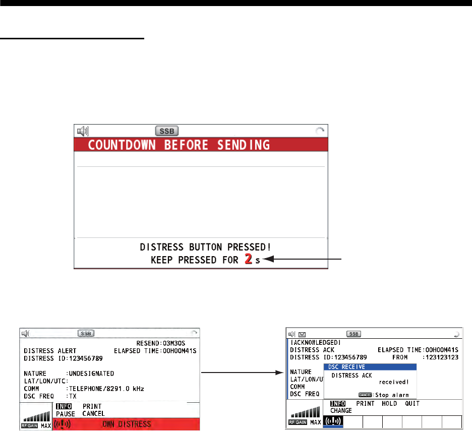
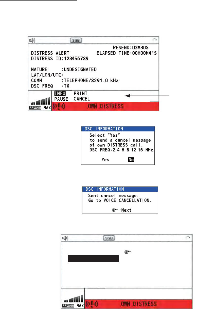
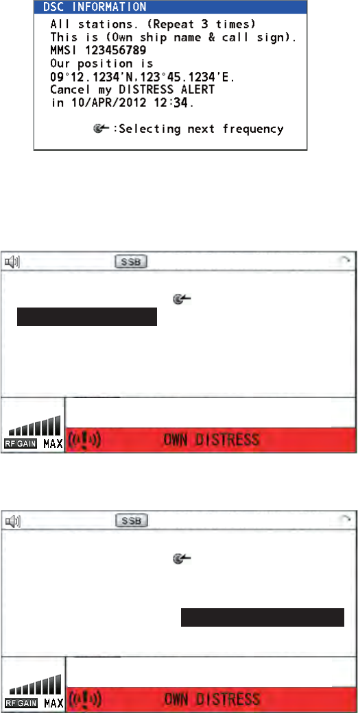
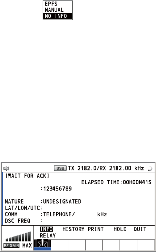
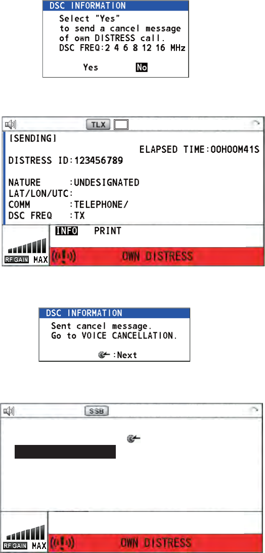
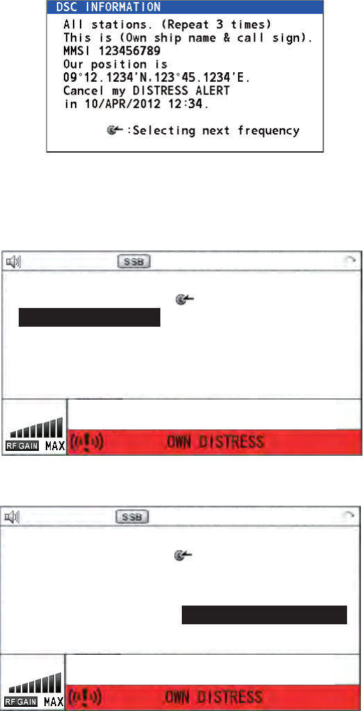
4.5 How to Cancel Distress Alert ................................................................................... 4-15
5. DSC GENERAL MESSAGE CALLING, RECEIVING............................................5-1
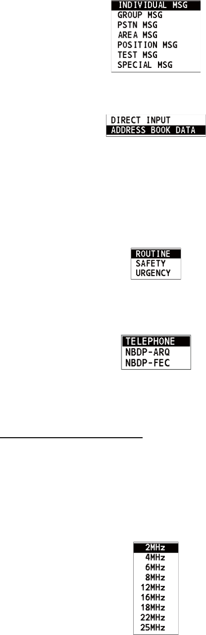
5.1 Individual Call............................................................................................................. 5-1
5.1.1 How to send an individual call........................................................................5-1
5.1.2 How to receive an individual call .................................................................... 5-6
5.2 Group Call ................................................................................................................ 5-10
5.2.1 How to send a group call.............................................................................. 5-10
5.2.2 How to receive a group call.......................................................................... 5-11
5.3 Geographical Area Call............................................................................................ 5-12
5.3.1 How to send a geographical area call.......................................................... 5-12
5.3.2 How to receive a geographical area call ...................................................... 5-14
5.4 Neutral Craft Call...................................................................................................... 5-14
5.4.1 How to send a neutral craft call....................................................................5-14
5.4.2 How to receive a neutral craft call ................................................................ 5-16
5.5 Medical Transport Call ............................................................................................. 5-17
5.5.1 How to send a medical transport call ........................................................... 5-17
5.5.2 How to receive a medical transport call ....................................................... 5-18
5.6 How to Receive a Polling Request...........................................................................5-19
5.6.1 Automatic reply ............................................................................................ 5-19
5.6.2 Manual reply................................................................................................. 5-19
5.7 Position Call ............................................................................................................. 5-20
5.7.1 How to request other ship's position ............................................................ 5-20
5.7.2 Other ship requests your position ................................................................5-22
5.8 PSTN Call ................................................................................................................ 5-23
5.8.1 How to send a PSTN call ............................................................................. 5-23
5.8.2 How to receive a PSTN call ......................................................................... 5-25
6. MENU OPERATION...............................................................................................6-1
6.1 How to Open/Close the MENU Screen ...................................................................... 6-1
6.2 User Channels ........................................................................................................... 6-2
6.2.1 List for user channels..................................................................................... 6-2
6.2.2 How to register user channels........................................................................ 6-2
6.2.3 How to edit user channels.............................................................................. 6-3
6.2.4 How to delete user channels.......................................................................... 6-4
6.2.5 How to sort the USER CH list by band........................................................... 6-4
6.2.6 How to select user channels for SSB mode................................................... 6-5
6.3 Log File ...................................................................................................................... 6-5
6.3.1 How to open a log file..................................................................................... 6-5
6.3.2 How to delete log files .................................................................................... 6-6
6.4 Squelch Frequency .................................................................................................... 6-7
6.5 Key Assignment ......................................................................................................... 6-7
6.6 How to Print Messages .............................................................................................. 6-8
6.7 Position Setting .......................................................................................................... 6-8
6.8 Date and Time Setting ............................................................................................... 6-9
6.9 Timeout Setting........................................................................................................ 6-10
6.10 FAX Enable/Disable .................................................................................................6-10
6.11 How to Select the Antenna....................................................................................... 6-11
6.12 Clarifier Setting......................................................................................................... 6-11
6.13 External Alarm Setting ............................................................................................. 6-12
6.14 NETWORK Setting................................................................................................... 6-12
6.15 Address Book........................................................................................................... 6-13
6.15.1 List for address data..................................................................................... 6-13
TABLE OF CONTENTS
ix
6.15.2 How to register addresses............................................................................6-13
6.15.3 How to edit addresses..................................................................................6-14
6.15.4 How to delete addresses..............................................................................6-15
6.15.5 How to create a DSC message with registered address..............................6-15
6.16 TX Message Preparation..........................................................................................6-16
6.16.1 List for message files....................................................................................6-16
6.16.2 Individual calls ..............................................................................................6-17
6.16.3 Group calls ...................................................................................................6-18
6.16.4 PSTN calls....................................................................................................6-18
6.16.5 Test call ........................................................................................................6-19
6.16.6 How to edit prepared messages...................................................................6-19
6.16.7 How to send prepared messages.................................................................6-20
6.16.8 How to delete prepared messages...............................................................6-20
6.17 How to Set the AUTO ACK Details...........................................................................6-21
6.18 Special Messages ....................................................................................................6-22
6.19 How to Set Scan Frequencies ..................................................................................6-22
6.20 Sound Setting ...........................................................................................................6-23
6.21 Alarm Lists................................................................................................................6-24
7. NBDP SYSTEM OVERVIEW .................................................................................7-1
7.1 How to Turn on the NBDP System .............................................................................7-1
7.2 Description of Equipment ...........................................................................................7-1
7.2.1 Terminal unit...................................................................................................7-1
7.2.2 Keyboard ........................................................................................................7-3
7.3 Encoding Setting ........................................................................................................7-4
7.4 Function Keys, Menu Operation.................................................................................7-5
7.4.1 Menu conventions ..........................................................................................7-5
7.4.2 Menu overview ...............................................................................................7-5
7.4.3 Function key description.................................................................................7-6
8. NBDP PREPARATIONS........................................................................................8-1
8.1 Registration of Answerback & ID Codes ....................................................................8-1
8.1.1 How to register answerback code ..................................................................8-1
8.1.2 How to register ID codes ................................................................................8-2
8.2 User Channels............................................................................................................8-2
8.2.1 How to register user channels........................................................................8-2
8.2.2 How to edit/delete user channels ...................................................................8-3
8.3 Station List..................................................................................................................8-3
8.3.1 How to register stations..................................................................................8-3
8.3.2 How to edit/delete stations .............................................................................8-5
8.4 Timer Programming....................................................................................................8-5
8.4.1 How to register timer programs ......................................................................8-5
8.4.2 How to edit/delete timer programs .................................................................8-6
8.5 Scan Channel Groups ................................................................................................8-6
8.5.1 How to register scan channel groups .............................................................8-7
8.5.2 How to edit/delete scan channel groups ........................................................8-8
8.6 How to Change the Window Color .............................................................................8-8
8.6.1 IB-583.............................................................................................................8-8
8.6.2 IB-585.............................................................................................................8-9
8.7 Screen Saver Function for IB-585 ............................................................................8-10
9. NBDP FILE OPERATIONS....................................................................................9-1
9.1 How to Open and Close Files.....................................................................................9-1
9.2 How to Create Files ....................................................................................................9-1
9.3 How to Save a File .....................................................................................................9-2
9.3.1 How to format floppy disks or SD cards .........................................................9-3
TABLE OF CONTENTS
x
9.3.2 How to save a file........................................................................................... 9-3
9.4 How to Edit Files ........................................................................................................ 9-3
9.4.1 How to cut and paste text............................................................................... 9-3
9.4.2 How to copy and paste text............................................................................ 9-4
9.4.3 Select all......................................................................................................... 9-4
9.4.4 How to search text ......................................................................................... 9-5
9.4.5 How to replace text ........................................................................................ 9-5
9.4.6 Goto line......................................................................................................... 9-6
9.4.7 Goto top, Goto bottom.................................................................................... 9-6
9.5 How to Open Files...................................................................................................... 9-6
9.5.1 Open a file...................................................................................................... 9-6
9.5.2 Switch between files....................................................................................... 9-7
9.6 How to Rename Files................................................................................................. 9-7
9.7 How to Save a File Under a New Name .................................................................... 9-7
9.8 How to Delete Files .................................................................................................... 9-8
9.9 Real Time Printing...................................................................................................... 9-8
9.10 How to Print Files ....................................................................................................... 9-8
10. NBDP TRANSMISSION, RECEPTION................................................................10-1
10.1 Manual Calling ......................................................................................................... 10-1
10.2 ARQ Mode Operation............................................................................................... 10-3
10.3 FEC Mode Operation ............................................................................................... 10-5
10.4 How to Select Reception Mode................................................................................ 10-5
10.5 Communication Example ......................................................................................... 10-6
10.6 Timer Operation ....................................................................................................... 10-8
10.6.1 How to enable timer operation ..................................................................... 10-8
10.6.2 How to stop timer operation ......................................................................... 10-8
10.7 Scanning .................................................................................................................. 10-9
10.8 Communication Buffer.............................................................................................. 10-9
10.9 Preparation of Macrofiles for Automatic Telex ....................................................... 10-10
10.9.1 Automatic telex overview ........................................................................... 10-10
10.9.2 Preparations...............................................................................................10-10
10.9.3 Commands.................................................................................................10-11
10.9.4 Store-and-forward method ......................................................................... 10-13
10.10Automatic Telex Using Macrofile ........................................................................... 10-15
11. MAINTENANCE & TROUBLESHOOTING..........................................................11-1
11.1 Test .......................................................................................................................... 11-1
11.2 Maintenance............................................................................................................. 11-3
11.3 Simple Troubleshooting ...........................................................................................11-4
11.4 Error Messages........................................................................................................ 11-4
11.5 Breaker on PR-850A ................................................................................................ 11-5
11.6 Test Call ...................................................................................................................11-5
11.7 NBDP Terminal Unit Maintenance ........................................................................... 11-6
11.7.1 Cleaning the equipment ............................................................................... 11-6
11.7.2 Connectors and earth connection ................................................................ 11-6
11.7.3 Floppy disk drive ..........................................................................................11-6
11.7.4 Diagnostics................................................................................................... 11-6
11.7.5 Power fuse ................................................................................................... 11-7
11.7.6 Notification messages for IB-585 ................................................................. 11-7
APPENDIX 1 MENU TREE .......................................................................................AP-1
APPENDIX 2 FREQUENCY TABLES.......................................................................AP-3
APPENDIX 3 LIST OF ABBREVIATIONS..............................................................AP-16
APPENDIX 4 DIGITAL INTERFACE (IEC 61162-1)...............................................AP-19
TABLE OF CONTENTS
xi
APPENDIX 5 PARTS LIST .....................................................................................AP-23
APPENDIX 6 PARTS LOCATION ..........................................................................AP-26
SPECIFICATIONS ..................................................................................................... SP-1
INDEX ......................................................................................................................... IN-1
xii
FOREWORD
A Word to the Owner of the FS-1575/2575/5075
Congratulations on your choice of the FURUNO FS-1575/2575/5075 SSB Radiotelephone. We
are confident you will see why the FURUNO name has become synonymous with quality and re-
liability.
Since 1948, FURUNO Electric Company has enjoyed an enviable reputation for innovative and
dependable marine electronics equipment. This dedication to excellence is furthered by our ex-
tensive global network of agents and dealers.
Your equipment is designed and constructed to meet the rigorous demands of the marine envi-
ronment. However, no machine can perform its intended function unless properly installed and
maintained. Please carefully read and follow the operation and maintenance procedures set forth
in this manual.
We would appreciate feedback from you, the end-user, about whether we are achieving our pur-
poses.
Thank you for considering and purchasing FURUNO equipment.
Features
The FS-1575/2575/5075 is an MF/HF SSB Radiotelephone with a built-in DSC/Watch Receiver,
all contained in a surprisingly compact cabinet. An NBDP (Narrow Band Direct Printing) Terminal
Unit is optionally available.
Data is displayed on a large, easy-to-read color LCD. Operation is simplified by the use of few
keys and easy-to-follow menus.
The built-in DSC/Watch Receiver produces and receives digital selective callings for quick and ef-
ficient establishment of distress, urgency, safety and routine communications with other ships and
coast stations that install any MF/HF DSC facilities.
The main features are
General
Fully meets the following regulations: IMO A.806(19), IMO A.694(17), MSC 36(63), MSC
68(68), IEC 61162-1 Ed.4, IEC 60945 Ed.4, ETS 300 067 Ed.1, EN 300 338, EN 300 373-1, EN
301 033, ITU-R M.476-5, ITU-R M.490, ITU-R M.491-1, ITU-R M.492-6, ITU-R M.493-13, ITU-
R M.541-9, ITU-R M.625-3, ITU-R M.821-1, ITU-R M.1082-1, ITU-R M.1173, MSC/Circ. 862.
Automatic entry of position with manual override
Optional printer can automatically print out DSC and NBDP received messages and test results.
DSC/Watch Receiver
Distress, urgency, safety and routine calling
Scanning of DSC frequencies for distress and general calls on MF/HF
File editing capability for readiness in case of emergency
PSTN (Public Switched Telephone Network) capability standard
FOREWORD
xiii
Log stores 50 each of latest general, distress and transmitted messages, in separate memory
blocks.
SSB
Receiving voice communication
Noise blanker function, Noise reduction function, Notch filter function, Squelch function are
available.
Simplified setting of channel and frequency
NBDP (with optional NBDP Terminal Unit IB-583/IB-585)
Automatic error-free telex communications and distress message in compliance with GMDSS
requirements
LCD monitor and keyboard comply with ITU regulations
Pop-up menus for user-friendly operation
Memory for 256 operator-customized channels
Real time message printing with Printer PP-510
Program Number
FS-1575/2575/5075
xx: minor change
Terminal Unit IB-583 (optional unit)
Terminal Unit IB-585 (optional unit)
Location PC board Program No. Version
FS-1575T/2575T/5075T
T-CPU (05P0859)
0550243 (APP) 01.xx
0550247 (Boot) 01.xx
MOT (05P0860) 0550245 (CPLD) 01.xx
FS-2575C C-CPU (05P0852) 0550246 (Boot) 01.xx
ANTENNA COUPLER AT-5075 COUP (05P0875) 0550244 01.xx
ANTENNA COUPLER AT-1575 COUP (05P0883) 0550244 01.xx
PC board Program No. Version
TERMINAL 0550209 1.22
PC board Program No. Version
TERMINAL 0550251 01.xx
xiv
SYSTEM CONFIGURATIONS
*
3
*
1
*
1
ANTENNA COUPLER
AT-1575 (FS-1575) or
AT-5075 (FS-2575, FS-5075)
PRINTER
INTERFACE
IF-8500*
2
PRINTER
PP-510
24
VDC
ALARM
SYSTEM
NAVIGATOR
EXTERNAL
EQUIPMENT
ALARM UNIT
IC-350
AUTOMATIC ANTENNA
SWITCH AS-102
EXTERNAL
LOUDSPEAKER
SEM-21Q
PREAMP
FAX-5
PREAMP
FAX-5
ANT. JUNC. BOX AJB1-1A or
MATCHING BOX ARD-1
*
1
2.6 m whip
antenna
WR BOARD
TRANSCEIVER
UNIT
FS-1575T
(FS-1575)
or
FS-2575T
(FS-2575)
or
FS-5075T
(FS-5075)
CONTROL UNIT
FS-2575C
NBDP TERMINAL UNIT
IB-583 or IB-585
24 VDC
*
2
Required for NBDP Terminal
and DSC to share printer.
AC-DC POWER
SUPPLY UNIT
PR-850A
(for FS-2575/5075)
24 VDC
100/110/120/200/220/240 VAC
1ø, 50/60 Hz
: STANDARD
: OPTION
: LOCAL SUPPLY
Unit Category
Preamp Unit
Antenna Coupler
Other Units
Exposed to the weather
Exposed to the weather or
protected from the weather
Protected from the weather
HANDSET
HS-2003
HANDSET
HS-2003
EXTERNAL
LOUDSPEAKER
SEM-21Q
BK INTERFACE
BK-300
*
3
For DSC routine frequency
watch keeping receiver
No. 2 CONTROL
UNIT FS-2575C
*
3
*
4
RX antenna
For DSC
For NBDP
KEYBOARD
5139U (IB-585)
G84-4100PPAUS (IB-583)
or
AC-DC POWER
SUPPLY UNIT
PR-300
(for FS-1575)
100/110/200/220 VAC
1ø, 50/60 Hz
*
4
1-1
1. OPERATIONAL OVERVIEW
1.1 Controls
Description of controls
Control Function
VOLUME/PWR knob Turns the power on or off.
Adjusts the volume.
ENTER knob Rotate to select menu items or change the page in multi-page screens (e.g.,
log data); push to confirm a selection.
RF GAIN/
PUSH TO ATT knob
Rotate to adjust the gain; push to turn the attenuator on or off.
DISTRESS key Press and hold down the key four seconds to transmit the distress alert.
MENU key Opens/closes the menu.
CANCEL key Cancels the creation of the DSC message currently being created.
Silences the audio alarm.
Erases error message or pop-up message.
Returns one layer in multi-layer menu.
Erases character input.
TAB key Switches control to the tab area.
• Switches the session.
key
Turns the main speaker on or off.
BRILL key Adjusts the brilliance.
OTHER DSC MSG
key
Composes DSC TX message except DISTRESS ALERT and DROBOSE
(Distress Relay On Behalf Of Someone Else).
DISTRESS MSG key Composes DSC TX message for DISTRESS ALERT.
DROBOSE MSG key Composes DSC TX message for DROBOSE (Distress Relay On Behalf Of
Someone Else). Press the DISTRESS MSG key and the OTHER DSC
MSG key simultaneously.
SCAN key Opens the scan screen.
Stops/starts the scanning of DSC routine frequencies, on the scan
screen.
2182 key Switches to the RT (radiotelephone) screen and sets freq. to 2182.0 kHz.
RT/CH key Switches to the RT (radiotelephone) screen.
Opens the CH setting window on the RT screen.
0 to 9 keys Enter alphabet, numeric or symbol.
1, 4 and 7 keys Execute the operation assigned to the function key in the RT mode.
SCAN 2182
RT/CH
1
2
NB
3
SQ
46
97
5
NR
8
NF
0
TUNE
COMPOSE
DROBOSE MSG
PUSH TO ENTER
DISTRESS
MSG
OTHER
DSC MSG
BRILL
TAB
MENU
CANCEL
HANDSET
VOLUME
PWR OFF
RF GAIN
PUSH TO ATT
OVEN
ALARM
DISTRESS
Keep pressed for 4 sec in case
of DISTRESS. The alert is
transmitted with steady lighting.
1. OPERATIONAL OVERVIEW
1-2
1.2 How to Turn On/Off the Power
Rotate the VOLUME/PWR knob clockwise to turn on the power. The RT screen ap-
pears.
To turn off the power, rotate the VOLUME/PWR knob counterclockwise to the OFF po-
sition.
In the dual control unit system, the No.1 control unit has priority and it controls the
power for both itself and the No. 2 control unit. The power switch of the No. 2 control
unit powers on/off the No. 2 control unit only.
Note: Turn on the power at the switchboard more than 15 minutes before turning on
this equipment.
1.3 Radiotelephone (RT) Screen
Turn the power on, or press the RT/CH key to show the RT (radiotelephone) screen.
This is where you set up the transceiver unit, and communicate by voice or telex.
Radiotelephone (RT) screen
2/NB key Turns the noise blanker on or off in the RT mode.
3/SQ key Turns the squelch on or off in the RT mode.
5/NR key Reduces the noise in the RT mode (NR2 (High), NR1 (Low), Off).
8/NF key Turns the notch filter on or off in the RT mode.
0/TUNE key Tunes the antenna in radiotelephone operation.
key
Turns down the handset volume.
Moves the cursor when setting channel or RX frequency.
key
Turns up the handset volume.
Moves the cursor when setting channel or RX frequency.
ALARM lamp Flashes in red for distress and urgency messages.
Flashes in green for safety and routine messages, and when daily test is
completed.
OVEN lamp Lights in green when the main switchboard is on.
Control Function
Function keys
Tab area: Sessions
in progress
Spinner: Rotates when
the equipment is
functioning normally.
1. OPERATIONAL OVERVIEW
1-3
1.4 DSC Scan Screen
Press the SCAN key to show the DSC scan screen. This screen scans and receives
the distress and routine frequencies.
Indication Meaning
Main speaker on or off
CH Channel
TX
TX frequency ( : while transmitting)
RX RX frequency
SSB/TLX/AM/FAX Class of emission
OFF/SLOW/FAST
(AGC)
Auto gain control ([OFF]: no adjustment, [SLOW]: low-speed, [FAST]: high-
speed)
HIGH/MID/LOW(1)/
LOW2
Output power ([LOW2]: FS-5075 only, minimum output power)
SIMP/S-DUP/DUP Communication mode ([SIMP]: simplex, [S-DUP]: semi-duplex, [DUP]: full-
duplex (only for FS-5075, option))
IA/IC/VC/RF/VS Transceiver unit status ([IA]: antenna current, [IC]: collector current,
[VC]: collector voltage, [RF]: RF output, [VS]: source voltage)
S S-meter, displays the strength of received signal.
NB
Noise blanker ( :On, No indication: Off)
NR2/NR1/OFF
Noise reduction ( : High, : Low, No indication: Off)
NF
Notch filter ( : On, No indication: Off)
SQ
Squelch ( : On, No indication: Off)
MMSI Own ship's ID (nine digits)
LAT, LON Own ship's position (LAT: Latitude, LON: Longitude)
EPFS Position data from EPFS
ATT
Attenuator ( : On, No indication: Off)
RF GAIN Adjusted value of gain
Maximum six distress and
routine frequencies scanned.
RX: Transceiver unit
(WR2 shown when optional
antenna for routine frequencies
is installed.)
135°19
.
5900
'
E
34°42
.
2800
'
N
1. OPERATIONAL OVERVIEW
1-4
1.5 How to Adjust the Brilliance of the Display and
Panel
You can adjust the brilliance of the display and the panel as follows:
1. Press the BRILL key to show the [BRILL LEVEL SETUP] window.
2. Press the 1 key to switch the [DAY/NIGHT] mode.
3. To adjust the [DISPLAY] brilliance, rotate the ENTER knob or press the BRILL
key.
(Default setting: 17 for [DAY], 7 for [NIGHT])
4. To adjust the [PANEL] brilliance, press the or key.
(Default setting: 17 for [DAY], 12 for [NIGHT])
5. Push the ENTER knob to save the settings and close the window. To cancel the
settings, press the CANCEL key instead of the ENTER knob to close the window.
Note 1: The equipment keeps values for [DAY] and [NIGHT] separately.
Note 2: The window closes automatically when there is no operation for four seconds.
Note 3: When you turn on the power with the display brilliance set to 0, the setting au-
tomatically changes to 1.
1.6 How to Turn On/Off the Main Speaker
You can turn the main speaker (other than DSC communication, error, and key beep)
on/off.
1. Press the key to alternately disable or enable the main speaker.
2. To adjust the volume of the main speaker, rotate the VOLUME/PWR knob (cw:
volume up, ccw: volume down).
1.7 How to Scan
The DSC screen scans multiple routine frequencies according to operator-set interval.
For how to set frequency to scan, see section 6.19.
Note: The voice and telex communication are not available when scanning.
Speaker ON
Speaker OFF
1. OPERATIONAL OVERVIEW
1-5
1. Press the SCAN key to show the DSC scan screen. Scanning starts. When re-
ceiving the appropriate frequency signal, the scanning stops, and the frequency
is highlighted and flashes.
2. Press the SCAN key again to stop scanning the routine frequencies.
Note: You can not stop the scanning manually for the distress alert.
3. Rotate the ENTER knob to move the cursor to the desired routine frequency which
you want to watch. You can scan only the frequency selected by cursor.
4. Press the SCAN key to restart the scanning.
Note: When scanning starts, the active session (refer to section 1.11) is automatically
put on hold.
1.8 How to Set the Auto Acknowledgement
Individual, PSTN (public switched telephone network), position, polling and test calls
can be acknowledged automatically or manually. This is set on the [ACK SETTINGS]
in the [DSC] menu (see section 6.17).
Note: When own ship's communication is high priority, set to manual acknowledge-
ment.
The auto acknowledgement is not sent in the following cases:
Other session is active (except individual call).
There are RT or DSC sessions (for individual call).
Channel is in use.
ECC is NG (No Good).
Note: The auto acknowledgement for the individual call is sent only when the pro-
posed channel or communication mode is not available.
1.9 Control Unit Priority
If you operate the No.1 control unit while the No.2 control unit is being operated, the
right to operate is shifted to the No.1 control unit. The control unit not having priority
shows the following:
The unit name currently in use: No.1 control unit, No.2 control unit or NBDP
The ongoing operation: COMPOSING DSC MESSAGE, OPERATION, COMMUNI-
CATION
The control unit which you operate has priority in the following conditions:
The handset goes OFF HOOK.
Display the menus or setting windows.
Display each function screen (for example, Log).
Press a key or rotate a knob. (The priority is lost after four seconds.)
• NBDP is communicating.
1. OPERATIONAL OVERVIEW
1-6
1.10 Intercom
The built-in intercom permits voice communications between two control units.
Calling
You can call over the intercom in on or off hook condition.
1. Press the MENU key.
2. Rotate the ENTER knob to select [INTERCOM] then push the knob. The pop-up
for calling appears and the called party's control unit rings. To cancel calling,
press the CANCEL key.
3. When the called party picks up their handset, the pop-up for calling disappears
and the INTERCOM CONNECTED screen appears. Start communications.
Note: You do not have to press the PTT switch to communicate.
4. If needed, adjust the handset volume with or key.
5. Hang up the handset or press the CANCEL key to turn the intercom off. The last-
used screen or the RT screen appears.
Answering
1. The control unit rings, and both the pop-up for calling and a message, which sug-
gests you to pick up the handset, appear. To cancel reply, press the CANCEL key.
2. Pick up the handset, and the alarm stops. The pop-up for calling disappears and
the INTERCOM CONNECTED screen appears. Start communications.
3. Hang up the handset or press the CANCEL key to turn the intercom off. The last-
used screen or the RT screen appears.
1.11 Operation of Session
Description of session
There are two types of sessions: RT session and DSC session. When a session starts,
the appropriate icon for the session appears in the tab area.
RT session
DSC sessions
Tab area
1. OPERATIONAL OVERVIEW
1-7
How to finish a single session
RT session
1. Press the TAB key to select the RT icon in the tab area.
2. Rotate the ENTER knob to select [QUIT] then push the knob.
DSC session
The cursor is in the tab area when the DSC session starts. Rotate the ENTER knob to
select [QUIT] then push the knob.
How to start a new session
When another session is active:
When sending the distress alert
, all sessions except the distress alert TX session
automatically close then the distress alert TX session starts.
When doing an RT session or sending a non-distress DSC message
, the currently
active session is put on hold then the RT session or non-distress DSC message TX
session starts.
When receiving a DSC message
, its session is put on hold.
When no other session is active:
When sending the distress alert
, all sessions except the distress alert TX session
automatically close then the distress alert TX session starts.
When sending a non-distress DSC message
, its session becomes the active ses-
sion.
Step 1: Press the TAB key
to select the RT icon.
Step 2: Rotate the ENTER
knob to select [QUIT].
Press the 6 key to
open the position
data window.
[SELECT AN ACK]
ELAPSED TIME:
INDIVIDUAL MSG 00
H
00
M
58
S
FROM :
123456789
CAPTAIN_2575
COMM MODE :
TELEPHONE
COMM FREQ :
TX 2170.0 /RX 2170.0
kHz
INFO PRINT HOLD QUIT
ACCEPT UNABLE PROPOSE
TX 2177.0/ RX 2177.00 kHz
Rotate the ENTER knob
to select [QUIT].
1. OPERATIONAL OVERVIEW
1-8
How to switch sessions
When one session is active and another message arrives, a new session for the re-
ceived message does not start automatically. Only one session can be active. For ex-
ample, when you are transmitting a DSC message and another message arrives, the
option [ACTIVE] appears to indicate the start of a new session.
[SELECT AN ACK]
INDIVIDUAL MSG ELAPSED TIME : 00H00M58S
FROM : 123456789
CAPTAIN_2575
COMM MODE : TELEPHONE
COMM FREQ : TX 2170.0 / RX 2170.0 kHz
ACTIVE INFO PRINT QUIT
TX 2182.0/ RX 2182.00 kHz
RT
Press the TAB key to move
the cursor to the tab area.
To select a session, press the
TAB key. The cursor is here.
[RT : SSB] CH : 200
TX : 2182.0 kHz
RX : 2182.00 kHz
Information for the session
selected by cursor.
With [ACTIVE] selected, push the ENTER knob to switch
the active session. To switch the option for the session
(ACTIVE, INFO, PRINT, QUIT), rotate the ENTER knob.
User options area
Tab area
(Continued on next page)
Information for the session
underlined in blue (RT in
this case)
[SELECT AN ACK] ELAPSED TIME:
INDIVIDUAL MSG 00H01M12S
FROM :
123456789 CAPTAIN_2575
COMM MODE :
TELEPHONE
COMM FREQ : TX 2170.0 /RX 2170.0 kHz
INFO PRINT HOLD QUIT
ACCEPT UNABLE PROPOSE
TX 2177.0/ RX 2177.00 kHz
RT
Only the screen for
the selected
session appears.
To finish this session, rotate the ENTER knob to
select [QUIT] then push the knob.
Note: When waiting for the ACK, that is, the
session is in progress, the confirmation message
appears. Rotate the ENTER knob to select [YES]
or [NO] then push the knob.
1. OPERATIONAL OVERVIEW
1-9
How to close a session
To manually close a session, select it with the TAB key. Rotate the ENTER knob to
select [QUIT] in the user options area then push the knob. The session icon disap-
pears from the tab area.
When there is no operation for specific time (see section 6.9), the inactive session is
automatically closed.
Processing when the number of session is maximum
A maximum of seven sessions can be displayed in the tab area. If a seventh session
starts, the following message appears on the screen. Press the CANCEL key to close
the message. Close a session to make space for the new session.
If the eighth session is for sending a distress alert, all sessions except that session
automatically close, and the session starts.
If the eighth session is for receiving DSC message, the lowest-priority session auto-
matically closes and the message appears.
[WAIT FOR ACK]
INDIVIDUAL MSG ELAPSED TIME : 00H05M24S
TO : 987654321
CAPTAIN_5075
COMM MODE : TELEPHONE
COMM FREQ : TX 2170.0 / RX 2170.0 kHz
ACTIVE INFO PRINT QUIT
TX 2177.0/ RX 2177.00 kHz
RT
NO ACTIVE
The icon disappears.
(Continued from
previous page)
1. OPERATIONAL OVERVIEW
1-10
This page is intentionally left blank.
2-1
2. SSB RADIOTELEPHONE
You can do SSB communications from any screen which displays the communication
frequency.
2.1 How to Select the Class of Emission
You can select the class of emission from among the following:
[SSB]: Single Sideband
• [TLX]: Telex
[AM]: AM (RX only)
[FAX]: FAX (RX only. Connect a FAX to this equipment to print FAX messages.)
At the RT screen, select the class of emission as follows:
1. Rotate the ENTER knob to highlight the class of emission (default: [SSB]) then
push the knob. When you rotate the ENTER knob clockwise, the cursor moves
from [CH] downward.
2. Rotate the ENTER knob to select the class of emission desired then push the
knob. AGC is automatically turned on or off according to the class of emission.
3. You can change AGC as below.
1) Rotate the ENTER knob to select the AGC mode indication then push the
knob.
2) Rotate the ENTER knob to select [OFF], [SLOW] or [FAST] then push the
knob.
2.2 How to Select the Channel, Frequency
Select the channel or transmitting/receiving frequency to use for the SSB.
Note: To set the SSB radiotelephone to 2182 kHz/J3E, press the 2182 key.
[SSB]: [FAST] [TLX], [FAX]: [OFF] [AM]: [SLOW]
Class of
emission
AGC mode
(Automatic Gain
Control)
This icon appears
when the frequency
is for distress.
2. SSB RADIOTELEPHONE
2-2
Channel
1. Rotate the ENTER knob to select [CH] on the RT screen then push the knob. You
can also show the channel setting window by pressing the RT/CH key.
2. A channel can be entered directly with the numeric keys, or by using the ENTER
knob. See below for details.
Enter channel with the numeric keys:
Use the numeric keys to enter channel then push the ENTER knob.
Select band and band channel with the
ENTER knob:
1) Use the or key to place the cursor in the band or band channel position,
whichever you want to change.
2) Rotate the ENTER knob to set band or band channel desired.
3) Push the ENTER knob to close the setting window.
Frequency
1. Rotate the ENTER knob to select [TX] or [RX] then push the knob.
2. Enter frequency by one of the methods below.
Enter frequency with the numeric keys:
Use the numeric keys to enter frequency then push the ENTER knob. For exam-
ple, to enter 2161 kHz, key in 2, 1, 6, 1, 0. (Note: Keying in 2-1-6-1 sets 216.1
kHz.) Be sure to include zero for 100 Hz place.
Select frequency with the
ENTER knob (for RX only):
1) Use the or key to change the range which the cursor covers.
2) Rotate the ENTER knob to set frequency desired.
3) Push the ENTER knob to close the setting window.
Note: When TX and RX frequencies are different, first enter TX then enter RX.
Channel setting
window
Cursor position for selection of band channel
2 0 0
Cursor position for selection of band
2 0 0
2 4 6 8 12 16 18 22 25 01 02----- 029
ITU band
User band
Setting Range
ITU Band (SSB, TLX): 2/4/6/8/12/16/18/22/25
ITU Band (CW): 4/6/8/12/16/22/25
User Band: 01-029 (First zero is necessary)
ITU Channel (SSB): 00 - XX
ITU Channel (TLX): 000 - XXX
ITU Channel (CW): 001 - XXX
User Channel: 01 - 99
2182.0
TX
RX
2182.00
2. SSB RADIOTELEPHONE
2-3
2.3 Transmission
After selecting the class of emission and frequency, you can transmit by pressing the
PTT switch on the handset.
2.3.1 Transmission procedure
Maximum transmission power is achieved only when the antenna impedance and
transmitter impedance match each other. Because the antenna impedance changes
with frequency, antenna impedance matching with the transmitter impedance is done
with the antenna coupler. The antenna coupler automatically tunes the transmitter to
a wide range of different antenna lengths. The available range is;
Wire antenna 10 to 18 meters long (horizontal part)
Whip antenna eight meters long (Horizontal feeder is two meters or longer.)
Whip antenna 10 meters long
To initiate the tuning, do the following:
1. Press the PTT switch on the handset. Tuning is automatically adjusted at first
transmission after frequency is changed. For manual tuning, press the 0/TUNE
key on the RT screen. If tuning fails, the message "TUNE NG" appears and the
output power is automatically set to [LOW] (for FS-1575/2575) or [LOW2] (for FS-
5075).
2. Hold the handset close to your mouth, press the PTT switch and speak clearly.
Note: When tuning is initiated in the two control unit system, the screen of the idle con-
trol unit shows "OCCUPIED (CONTROLLER 1 (or 2))". In this case, only the
DISTRESS key is operative on the idle control unit.
2.3.2 How to change transmission power
To minimize possible interference to other stations, reduce the transmission power.
This should be done when using the transceiver in a harbor, near the shore or close
to communication partner (other ship).
1. Rotate the ENTER knob to select [HIGH], [MID], [LOW] (for FS-1575/2575),
[LOW1] (for FS-5075) or [LOW2] (for FS-5075) (whichever is displayed), then
push the knob.
HIGH
MID
LOW1
LOW2
HIGH
MID
LOW
For FS-5075
For FS-1575/2575
135°19
.
5900
'
E
34°42
.
2800
'
N
2. SSB RADIOTELEPHONE
2-4
2. Rotate the ENTER knob to select the option desired then push the knob.
Note: The temperature of the power amplifier is monitored. When its temperature ris-
es above a certain temperature, output power is automatically reduced.
2.3.3 Condition of the transmitter
While transmitting, you can display [IA] (antenna current), [IC] (collector current), [VC]
(collector voltage), [RF] (RF output) or [VS] (source voltage) on the RT screen.
1. Rotate the ENTER knob to select [IA], [IC], [VC], [RF] or [VS] (whichever is dis-
played) then push the knob.
2. Rotate the ENTER knob to select the option desired then push the knob.
Check the transmission power
During transmission, the IA bar deflects according to the current being fed from the
antenna coupler to the antenna feeder. The unit of readout is amperes. The antenna
current varies with the effective antenna impedance. The reading differs by the fre-
quency and antenna length. The output power is proportional to the square of an an-
tenna current.
FS-1575/2575 FS-5075
[HIGH] No reducing
[MID] 125 Wpep 350 Wpep
[LOW] 90 Wpep -
[LOW1] - 200 Wpep
[LOW2] - 110 Wpep
Antenna
current
2. SSB RADIOTELEPHONE
2-5
2.4 Reception
Check if the class of emission and receiving frequency are set properly. If necessary,
set them again referring to sections 2.1 and 2.2.
2.4.1 RF gain (sensitivity) adjustment
In normal use the sensitivity should be set for maximum. If the audio on the received
channel is unclear or interfered with other signals, adjust (usually reduce) sensitivity
to improve clarity.
Rotate the RF GAIN/PUSH TO ATT knob to adjust gain (sensitivity).
The setting value is displayed at the lower left-hand side of the
screen, with analog and digital indications.
2.4.2 S-meter
The S-meter shows relative signal strength coming into the receiver front end.
2.4.3 Receive AM broadcasting stations
1. If the RT screen is not displayed, press the RT/CH key to display the RT screen.
2. Rotate the ENTER knob to select the current class of emission then push the
knob.
3. Rotate the ENTER knob to select [AM] then push the knob (see section 2.1).
4. Rotate the ENTER knob to select [RX] then push the knob.
5. Enter RX frequency with the numeric keys then push the ENTER knob (see "Fre-
quency" in section 2.2).
2.4.4 Noise blanker
The noise blanker removes pulse noise. Press the 2/NB key on the RT screen to turn
the noise blanker on and off alternately. When the noise blanker function is active,
is displayed on the RT screen.
2.4.5 Noise reduction
The noise reduction circuit analyzes speech component and noise component, and
reduces only noise component. Press the 5/NR key on the RT screen. Each time you
press the 5/NR key, the effect of noise reduction changes in the sequence of ([NR2]
S-meter
2. SSB RADIOTELEPHONE
2-6
(High) [NR1] (Low) Off). When the noise reduction function is active, or
is displayed on the RT screen.
2.4.6 Notch filter
The notch filter removes mixed CW (continuous wave) or beat signal interference.
Press the 8/NF key on the RT screen to turn the notch filter on and off alternately.
When the notch filter function is active, is displayed on the RT screen.
2.4.7 Squelch
Squelch on/off
The squelch mutes the audio output in the absence of an incoming signal. Press the
3/SQ key on the RT screen to turn the squelch on and off alternately. When radio noise
is too jarring during stand-by condition, it can be muted by activating the squelch.
When the squelch function is active, is displayed on the RT screen.
Squelch frequency
To adjust the squelch frequency, see section 6.4.
2.4.8 Attenuator
The attenuator reduces total gain and prevents saturation. Push the RF GAIN/PUSH
TO ATT knob on the RT screen to turn the attenuator on and off alternately. When the
attenuator function is active, is displayed on the RT screen.
2.5 User Channels
The [USER CH] menu provides for registration of user TX and RX channels, where
permitted. For further details, contact your dealer. See section 6.2 for the procedure.
NOTICE
FURUNO will assume no responsibility
for the disturbance caused by the
unlawful or improper setting of user
channels.
3-1
3. DSC OVERVIEW
3.1 What is DSC?
DSC is an acronym meaning Digital Selective Calling. It is a digital distress and gen-
eral calling system in the MF and HF bands used by ships for transmitting distress
alerts and general calls and by coast stations for transmitting the associated acknowl-
edgements.
For DSC distress, safety and urgency callings in the MF and HF bands, the frequen-
cies are 2187.5, 4207.5, 6312.0, 8414.5, 12577.0, and 16804.5 kHz.
3.2 DSC Message
DSC calls are roughly divided in two groups: distress messages and general (safety,
urgency and routine) messages. Below are the types of DSC messages.
*SPECIAL MSG: To send these messages, set [SPECIAL MSG] to [ABLE]. See
section 6.18.
Call Description
DISTRESS ALERT Your ship sends distress message.
DISTRESS RELAY
AREA
Your ship relays distress call to all ships in a specific geographical area.
DISTRESS RELAY
INDIVIDUAL
Your ship relays distress call to a coast station.
MEDICAL MSG* Inform areas that your ship is carrying medical supplies.
NEUTRAL MSG* Inform areas that your ship is not a participant in armed conflict.
INDIVIDUAL MSG Call to a specific address.
PSTN MSG Call over Public Switched Telephone Network (PSTN).
TEST MSG Send test signal to a station to test your station's functionality.
GROUP MSG Call to a specific group.
AREA MSG Call to all ships in a specific geographical area.
POSITION MSG Your ship requests position of other ships.
POLLING MSG Confirm if your ship is within communicating range with other ships. (Re-
ceive and answer only)
Distress, Safety, Urgency DSC calls
Routine DSC Call
Option
Routine DSC Call
TRANSCEIVER
UNIT
CONTROL UNIT
Distress, Safety, Urgency and Routine DSC Calls
3. DSC OVERVIEW
3-2
Contents of a DSC call
Calling category
Station ID (MMSI)
Your ship ID and sending station ID. Coast station ID begins with 00; Group ID be-
gins with 0.
Priority
Distress: Grave and imminent danger and request immediate assistance.
Urgency: A calling station has a very urgent call to transmit concerning safety of
ship, aircraft or other vehicle or safety of person.
Safety: A station is about to transmit a call containing an important navigational or
meteorological warning.
Routine: General calling
Communication mode
TELEPHONE: Telephone (J3E) by SSB radiotelephone
NBDP-ARQ*: Telex (J2B) mode ARQ via NBDP Terminal Unit
NBDP-FEC*: Telex (J2B) mode FEC via NBDP Terminal Unit
*: NBDP terminal unit is required.
Communication frequency
Working frequency used to call by telephone or NBDP. The sending station may
have the receiving station (ship or coast station) assign the frequency to use.
Position
Position can be automatically or manually set.
DSC frequency
DSC frequency to use. If the call priority is SAFETY, URGENCY or DISTRESS, se-
lect a DSC distress frequency.
End code
The end of a DSC call is indicated with "EOS" (acknowledgement, acknowledge-
ment required, no acknowledgement required).
3.3 Audio Alarms
When you receive a distress alert or general call addressed to your ship, the audio and
visual alarms are released. The audio alarm can be silenced with the CANCEL key.
Call category Call
DISTRESS DISTRESS ALERT, DISTRESS RELAY AREA, DISTRESS
RELAY INDIVIDUAL
GENERAL MEDICAL MSG, NEUTRAL MSG, INDIVIDUAL MSG, PSTN MSG,
TEST MSG, GROUP MSG, AREA MSG, POSITION MSG,
POLLING MSG
Alarm Frequency (interval)
Safety call received 750 Hz and 650 Hz (50 ms)
Routine call received 750 Hz and 650 Hz (50 ms)
While DISTRESS key is pressed for four
seconds
2000 Hz and 0 Hz (500 ms)
3. DSC OVERVIEW
3-3
3.4 Description of Call Screens
This section provides the information necessary for interpreting the receive and send
call screens.
3.4.1 RX calls
Below are sample distress alert and individual RX call screens. The contents of other
types of RX calls are similar to that of the individual call.
Distress alert
Individual RX call
Distress alert sent 2200 Hz, continuous (2 seconds)
Own ship position not updated 2000 Hz (250 ms) and 0 Hz (500 ms)
Distress alert call received 2200 Hz and 1300 Hz (250 ms)
Distress relay call received 2200 Hz and 1300 Hz (250 ms)
Distress relay ack call received 2200 Hz (500 ms) and 1300 Hz (500 ms)
Distress ack call received 2200 Hz (500 ms) and 1300 Hz (500 ms)
Urgency call received 2200 Hz and 0 Hz (250 ms)
Urgency ack call received 2200 Hz and 0 Hz (500 ms)
Alarm Frequency (interval)
Working frequency
to use
Call type
Elapsed time since
distress alert received
ID No. (MMSI)
of ship in
distress
Communication
mode and
suggested
channel
Available user options
Session in progress
RF gain
Speaker icon
DSC frequency
Position of ship
in distress
Nature of distress
Distance to ship
in distress
34
°
42.2800’N/135
°
19.5900’W/14:12
Working frequency
to use
Speaker icon
Elapsed time since
call received
ID No. (MMSI)
of ship
sending this
message
Communication
frequency
RF gain
Available user options
Communication mode
Session in progress
Call type
[SELECT AN ACK]
INDIVIDUAL MSG
ELAPSED TIME:
00
H
00
M
16
S
FROM :
COMM MODE
:
COMM FREQ
:
123456789
TELEPHONE
TX 2170.0/RX
2170.0 kHz
S
ACCEPT
B
TX 2177.0
/
RX 2177.00kHz
3. DSC OVERVIEW
3-4
The marks "*", "-" appear on the DSC receiving screen in the following conditions:
"*" indicates a corrupt character in received data.
"-" indicates missing digits after decimal point when receiving position data with no
info for expansion (expansion: digits after decimal point).
Examples:
1) When receiving position data without expansion, the indication is
"LAT: 12°34’N".
2) When receiving position data with expansion, the indication is
"LAT: 12°34,5678’N".
3) When receiving position data with no info for expansion, the indication is
"LAT: 12°34,----’N".
3.4.2 TX calls
Below are sample distress alert and individual TX call screens. The contents of other
types of TX calls are similar to that of the individual call.
Distress alert
Individual TX call
Nature of Distress
Position of ship in distress (your
ship) and time of distress position
Communication mode and
communication frequency
DSC frequency to send distress call
Message type
(Individual)
ID No. of station
where message
is to be sent
Priority (Routine,
Safety, Urgency)
Communication
mode
(Telephone,
NBDP-ARQ,
NBDP-FEC)
Communication
frequency
DSC frequency
4-1
4. DSC DISTRESS OPERATIONS
Distress operation overview
1. Press the DISTRESS key.
2. Wait for the distress alert acknowledgement.
3. Communicate with the coast station.
4.1 How to Send Distress Alert
GMDSS ships carry a DSC terminal with which to transmit the distress alert in the
event of a life-endangering situation. A coast station receives the distress alert and
sends the distress alert acknowledge call to the ship in distress. Then, voice or telex
communication between the ship in distress and coast station begins. Transmission
of the distress alert and receiving of the distress alert acknowledgement are complete-
ly automatic - simply press the DISTRESS key to initiate the sequence.
There are three types of distress alerts; MULTI, SINGLE, AUTO. MULTI is used nor-
mally. To use another method, see step 10 in paragraph 4.1.2.
Note: After sending the distress alert, no control unit has priority.
4.1.1 How to send distress alert by DISTRESS key with distress in-
formation not edited
1. Open the DISTRESS key cover then press the DISTRESS key for four seconds.
The audio alarm sounds while pressing the key, and the key flashes in red. The
countdown message appears on the screen while pressing the DISTRESS key
(3S 2S 1S 0S).
(3)
(2)
(1)
Ship in distress
(Your ship)
(1) Ship in distress sends Distress Alert.
(2) Coast station sends distress acknowledgement (DIST ACK).
(3) Voice or telex communication between ship in distress and coast station.
Coast
station
Countdown message
TX 2182 . 0 / RX 2182 . 00 kHz
MSG TYPE : D
I
STRESS ALERT
NATURE : UNDES
I
GNATED
LAT :
09
°
12.1234
’ N
LON/UTC :
123
°
45.1234
E / 12 : 34
COMM MODE
: TELEPHONE
DSC FREQ : MULTI 2 4 6 8 12 16MHz
4. DSC DISTRESS OPERATIONS
4-2
When the countdown shows 0S, the distress alert is sent. The audio alarm sounds
for two seconds and the message "Sending DISTRESS ALERT." appears. The
screen shows the contents of the distress alert call. The DISTRESS key lights in
red and only the icon for DISTRESS transmission ( ) is displayed in the tab ar-
ea.
After the distress alert has been sent, the screen changes as below. Wait to re-
ceive the distress acknowledge call from a coast station. The elapsed time since
transmission is displayed. At this time, the icons for other DSC received messag-
es except the distress alert acknowledge call are not displayed. You can only con-
firm them in the log.
Note: If you do not receive the distress alert acknowledge call, the equipment au-
tomatically re-transmits the distress alert after 3 min 30 seconds to 4 min 30 sec-
onds. Then awaits the distress alert acknowledge call. This is repeated until the
distress alert is acknowledged.
You can temporarily stop the countdown for next retransmission by selecting
[PAUSE] in the user options area. [PAUSE] indication changes to [START] and
[PAUSE] is displayed instead of the countdown indication. To restart, select
[START]. The countdown restarts and [START] indication in the user options area
changes to [PAUSE].
Also, you can re-send the distress alert manually by pressing the DISTRESS key
for four seconds.
When the distress acknowledge call is received, the audio alarm sounds, the LED
flashes in red, and the icon for DISTRESS transmission ( ) appears. The
screen changes as below.
Elapsed time
since distress
alert transmission
User options area
PRINT
TX 2182 . 0 / RX 2182 . 00 kHz
09
°
12.1234’ N/ 123
°
45.1234’ E / 12 : 34
Tab area
CHANGE
[ WAIT FOR ACK ]
2, 4, 6, 8, 12, 16
MH
z
E
/
12:34
4. DSC DISTRESS OPERATIONS
4-3
2. Press the CANCEL key to silence the audio alarm. Then, the LED stops flashing,
and the pop-up message disappears.
3. Communicate with the coast station via radiotelephone, following the instructions
below. If the distress alert was sent using the MULTI mode, the radiotelephone
automatically sets the working frequency on which the distress acknowledge call
is first received.
a) Say “MAYDAY” three times.
b) Say “This is ...” name of your ship and call sign three times.
c) Give nature of distress and assistance needed.
d) Give description of your ship (type, color, number of persons onboard, etc.).
4.1.2 How to send distress alert by DISTRESS key with distress in-
formation edited
If you have a time to prepare the distress information, send the distress alert as fol-
lows:
1. Press the DISTRESS MSG key to display the following screen.
2. With [NATURE] selected, push the ENTER knob.
3. Rotate the ENTER knob to select nature of distress, among the following 11 se-
lections, then push the knob.
• UNDESIGNATED • FIRE • FLOODING
• COLLISION • GROUNDING • LISTING
• SINKING • DISABLED&ADR(IFT) • ABANDONING
• PIRACY • MAN OVERBOARD
Count up the elapsed time
after receiving distress
acknowledge call.
Icon for DISTRESS transmission
09
°
12.1234’ N/ 123
°
45.1234’ E / 12 : 34
4. DSC DISTRESS OPERATIONS
4-4
4. With [LAT] and [LON/UTC] selected, push the ENTER knob.
[EPFS]: The position information from EPFS is automatically shown.
[MANUAL]: Input your position manually.
[NO INFO]: No information.
5. Rotate the ENTER knob to select [EPFS], [MANUAL] or [NO INFO] then push the
knob. For [MANUAL], go to step 6. For others, go to step 7.
6. Use the numeric keys to enter latitude, longitude and UTC time. (If necessary,
switch coordinates: 1 key to switch to North (East for longitude); 2 key to switch to
South (West for longitude).) Push the ENTER knob.
7. With [COMM MODE] selected, push the ENTER knob.
8. Rotate the ENTER knob to select [TELEPHONE] or [NBDP-FEC] then push the
knob.
9. With [DSC FREQ] selected, push the ENTER knob.
10. Rotate the ENTER knob to select the DSC frequency desired then push the knob.
[MULTI]: Transmit the distress alert on three to six frequencies (in numerical or-
der), which you can select among 2 MHz, 4 MHz, 6 MHz, 8 MHz, 12 MHz and 16
MHz. 2 MHz and 8 MHz are automatically selected and cannot be excluded.
[SINGLE]: You can transmit on the distress frequency of your selection. Select
one frequency among 2 MHz, 4 MHz, 6 MHz, 8 MHz, 12 MHz and 16 MHz.
[AUTO]: Transmit the distress alert on 2 MHz at first (40 to 60 seconds). If the dis-
tress alert is not acknowledged, transmission occurs in this sequence:
2nd: 8 MHz, 3rd: 16 MHz, 4th: 4 MHz, 5th: 12 MHz and 6th: 6 MHz
Latitude setting window
Longitude setting window
Push the
ENTER knob.
Push the
ENTER knob.
UTC setting window
Push the
ENTER knob.
Rotate the ENTER knob to select the
desired frequency then push the
knob. Each push of the ENTER knob
displays (selected) or removes
(deselected) the asterisk.
A
fter setting, rotate the ENTER knob to
select [EXIT] then push the knob.
4. DSC DISTRESS OPERATIONS
4-5
11. Press the DISTRESS key for four seconds to send the distress alert. The audio
alarm sounds while pressing the key, and the key flashes in red. The countdown
message appears on the screen while pressing the DISTRESS key (3S 2S
1S 0S) (refer to the illustration at step 1 in paragraph 4.1.1). When the count-
down shows 0S, the distress alert is sent. The audio alarm sounds for two sec-
onds and the message "Sending DISTRESS ALERT." appears.
12. When the distress acknowledge call is received, use the telephone or telex to
communicate with the coast station. For NBDP, follow the procedure in “Commu-
nicating by NBDP terminal unit” on this page. For telephone, follow step 3 on
paragraph 4.1.1. If you selected [MULTI] at step 10, you can communicate via
telephone, on the communication frequency which the distress acknowledge call
is received. If it is necessary to change the frequency, do the following:
1) Rotate the ENTER knob to select [CHANGE] in the user options area then
push the knob.
2) Rotate the ENTER knob to select the appropriate frequency then push the
knob.
Communication by NBDP terminal unit
One of the following messages appear on the NBDP's screen.
For IB-583
: "STATION ENTRY COMPLETED FROM DSC. Press any key to escape."
For IB-585
: "DSC activates NBDP. To start call, select "DSCxx" in F3-1 Station Call.
Press any key to escape."
1. Press any key on the NBDP terminal unit to erase the message.
2. Press the function key F3 on the keyboard of the NBDP terminal unit to open the
[Operate] menu.
3. Select [Call Station] then press the ENTER knob.
4. With [DSC] selected, press the Enter key to connect the communication line.
"Connect" appears in reverse video.
09
°
12’ N/ 123
°
45’ E / 12 : 34
INFO PRINT HOLD QUIT
CHANGE
For IB-585, these items are not displayed
when sending the distress alert.
4. DSC DISTRESS OPERATIONS
4-6
5. Type and transmit your message, giving the following information:
Ship's name and call sign
Nature of distress and assistance needed
Description of your ship
6. Press the function key F10 to disconnect the line.
For NBDP details, see chapters 7 through 10.
4.2 How to Receive a Distress Alert
When you receive a distress alert from a ship in distress, the audio alarm sounds and
the LED flashes in red. The icon for DISTRESS receiving ( ) appears in the tab area
and the pop-up message "DISTRESS ALERT message received! [CANCEL]: Stop
alarm" appears on the screen.
Press the CANCEL key to silence the audio alarm. Wait for the distress acknowledge
call from a coast station. If you do not receive the distress acknowledge call from a
coast station, which usually takes about five minutes from the time of receiving a dis-
tress alert, follow the flow charts in this section to determine your action.
Note: An asterisk (*) appearing in a distress alert message indicates an error at the
asterisk’s location.
4.2.1 Distress alert received on MF band
Do the following:
Continue watching on 2182 kHz. Wait for coast station to acknowledge the distress
call. Watch until “SEELONCE FINI” is announced.
If multiple DSC distress alerts are received from the same ship in distress and it is
near your ship, communicate with RCC or coast station and send distress acknowl-
edge call to the ship in distress under the direction of RCC or coast station.
Watch on the distress frequency.
E
/
12:34
4. DSC DISTRESS OPERATIONS
4-7
Action for ship receiving distress alert on MF band
Send the distress acknowledge call to ship in distress (on MF band)
Note: You must wait at least five minutes before you can acknowledge a distress alert,
to allow time for a coast station to transmit the distress acknowledge.
Transmit the distress acknowledge call to the ship in distress only when you do not
receive it from a coast station and you are able to aid the ship in distress. First, contact
the ship in distress over radiotelephone.
When you receive a distress alert from a ship in distress, the audio alarm sounds and
the LED flashes in red. The icon for DISTRESS receiving appears in the tab area and
the pop-up message "DISTRESS ALERT message received! [CANCEL]: Stop alarm"
appears on the screen.
To terminate transmission of the distress alert, send acknowledge call as follows.
1. Press the CANCEL key to silence the audio alarm and stop the flashing of the
LED.
DSC distress alert received.
Press the CANCEL key
to silence alarm.
Listen on 2182 kHz
for 5 minutes.
Did you receive
acknowledge from
CS and/or RCC?
No
No
No
Yes
Yes
Yes
Yes
No
Is distress traffic
in progress?
Is the DSC
distress call
continuing?
Is your ship
able to aid
ship in
distress?
Acknowledge the alert by
radiotelephone to the ship
in distress on 2182 kHz.
Inform CS and/or RCC.
Enter details in log.
CS = Coast Station
RCC = Rescue Coordination Center
09
°
12.1234’ N/ 123
°
45.1234’ W / 12 : 34
2182 . 0
2187 . 5 kHz
4. DSC DISTRESS OPERATIONS
4-8
2. If you do not receive the distress acknowledge call from a coast station and you
have received the distress alert more than twice, contact the ship in distress over
radiotelephone.
3. Rotate the ENTER knob to select [ACK] in the user options area then push the
knob. The following message appears on the screen.
4. Rotate the ENTER knob to select [Yes] then push the knob to transmit the distress
acknowledge call to the ship in distress. The screen changes as below.
Note: You can not edit the message for the distress acknowledge call.
4.2.2 Distress alert received on HF band
If you receive a distress alert on the HF band, the audio alarm sounds and the LED
flashes in red. The icon for DISTRESS receiving ( ) appears in the tab area and the
pop-up message "DISTRESS ALERT message received! [CANCEL]: Stop alarm" ap-
pears on the screen. Press the CANCEL key to silence the audio alarm and stop the
flashing of the LED. The screen for receiving the distress alert appears. Wait for the
distress acknowledge call from a coast station. If you do not receive the distress ac-
knowledge call from a coast station, which usually takes about five minutes from the
time of receiving a distress alert, follow the flow chart in this section to determine your
action.
Watch on the distress frequency.
FROM
: 987654321
[ SENDING ]
09
°
12.1234’ N/ 123
°
45.1234’ W / 12 : 34
FROM
: 987654321
[ SENDING ]
09
°
12.1234’ N/ 123
°
45.1234’ W / 12 : 34
[ACKNOWLEDGED]
DI ST
R
ESS ACK
00
H
0
1M1
8
S
HOLD QUIT
RELAY ACK CHANGE
DI ST
R
ESS ACK
2187.5
/
RX 2187.50 kHz
2182.0
TX 2187.5 kHz
TX 2182.0
/
RX 2182.00 kHz
2182.0
TX 2187.5 kHz
4. DSC DISTRESS OPERATIONS
4-9
Relay the distress alert in the following cases:
You have not received a distress acknowledge call from a coast station within five
minutes after receiving a distress call.
You have not received a distress relay from other ship.
You cannot receive distress communications from other ship over radiotele-
phone.
The ship relaying the distress alert should establish communications with the sta-
tion controlling the distress as directed and render such assistance as required
and appropriate.
If it is clear the ship or persons in distress are not near your ship and/or other ves-
sels are better placed to assist, superfluous communications which could interfere
with search and rescue activities should be avoided. Details should be recorded in
the log.
When the received distress frequency is different from the current communication
frequency, do the following:
1. Rotate the ENTER knob to select [CHANGE] then push the knob.
2. Rotate the ENTER knob to select the frequency same as the received distress
one then push the knob.
Action for ship receiving distress alert on HF band
No
Yes
Yes
Yes
No
No
DSC distress alert received.
Press the CANCEL key
to silence alarm.
Listen to associated RTF* or
NBDP channel(s) for 5 minutes.
Is the alert
acknowledged or
relayed by CS and/
or RCC?
HF DSC, RTF AND NBDP CHANNELS (kHz)
* = Radiotelephone
DSC RTF* NBDP
4207.5
6312.0
8414.5
12577.0
16804.5
4125
6215
8291
12290
16420
4177.5
6268
8376.5
12520
16695
Is distress
communication in
progress on
associated RTF*
channels?
Transmit distress
relay on HF to CS
and inform RCC.
Is your ship
able to
assist?
Contact RCC via most
efficient medium to
offer assistance.
CS = Coast Station
RCC = Rescue Coordination Center
Enter details in log.
4. DSC DISTRESS OPERATIONS
4-10
Send the distress relay to coast station (on HF band)
When you receive a distress alert from a ship in distress, the audio alarm sounds and
the LED flashes in red. The icon for DISTRESS receiving ( ) appears in the tab area
and the pop-up message appears on the screen.
1. Press the CANCEL key to silence the audio alarm and stop the flashing of the
LED.
2. Rotate the ENTER knob to select [RELAY] in the user options area then push the
knob.
If three minutes have not passed after receiving the distress alert from the ship in
distress, the following message appears on the screen. If you are sure to acknowl-
edge the distress call, rotate the ENTER knob to select [Yes] then push the knob
to erase the pop-up message and show the above screen.
3. Rotate the ENTER knob to select [TO] then push the knob.
4. Rotate the ENTER knob to select [DIRECT INPUT] or [ADDRESS BOOK DATA]
then push the knob.
[ADDRESS BOOK DATA]: Select an MMSI from the [ADDRESS BOOK] (see
section 6.15) then push the ENTER knob.
[DIRECT INPUT]: Enter the MMSI of the coast station, where to send the distress
relay, with the numeric keys then push the ENTER knob.
5. With [DSC FREQ] selected, push the ENTER knob.
6. Rotate the ENTER knob to select a frequency then push the knob. You should first
select [8414.5 kHz].
7. With [GO TO CALL] selected, push the ENTER knob. The screen changes to the
one for transmitting. After transmitting, the WAIT FOR ACK screen appears.
4. DSC DISTRESS OPERATIONS
4-11
When you receive the distress relay individual acknowledgement from the coast sta-
tion, the audio alarm sounds and a pop-up message appears. Press the CANCEL key
to silence the alarm and erase the pop-up message. Communicate with the coast sta-
tion by telephone, over the frequency specified. If you do not receive the distress ac-
knowledgement from a coast station, select [RELAY] then push the ENTER knob to
transmit the distress relay again, over a different frequency.
4.3 How to Send Distress Relay on Behalf of a Ship
in Distress
4.3.1 How to send distress relay to coast station
You can send the distress relay to a coast station on behalf of a ship in distress in the
following cases:
You are near the ship in distress and the ship in distress cannot transmit the distress
alert.
When the master or person responsible for your ship considers that further assis-
tance is necessary.
Note: Do not use the DISTRESS key to relay distress.
1. Press the DISTRESS MSG key and the OTHER DSC MSG key simultaneously to
open the composing screen for the distress relay individual.
2. With [TO] selected, push the ENTER knob.
3. Rotate the ENTER knob to select [DIRECT INPUT] or [ADDRESS BOOK DATA]
then push the knob.
[ADDRESS BOOK DATA]: Select an MMSI from the [ADDRESS BOOK] (see
section 6.15) then push the ENTER knob.
[DIRECT INPUT]: Enter the MMSI of the coast station, where to send the distress
relay, with the numeric keys then push the ENTER knob.
4. With [DISTRESS ID] selected, push the ENTER knob.
5. Rotate the ENTER knob to select [DIRECT INPUT] or [NO INFO] then push the
knob. For [DIRECT INPUT], go to step 6. For [NO INFO], go to step 7.
6. Enter the ID (MMSI) of the ship in distress with the numeric keys then push the
ENTER knob.
7. With [NATURE] selected, push the ENTER knob.
4. DSC DISTRESS OPERATIONS
4-12
8. Rotate the ENTER knob to select nature of distress then push the knob.
9. With [LAT] and [LON/UTC] selected, push the ENTER knob.
10. Rotate the ENTER knob to select [EPFS], [MANUAL] or [NO INFO] then push the
knob. For [MANUAL], go to step 11. For others, go to step 12.
11. Use the numeric keys to enter latitude and longitude of the ship in distress. (If nec-
essary, switch coordinates: 1 key to switch to North (East for longitude); 2 key to
switch to South (West for longitude).) Push the ENTER knob. Also, enter the UTC
time then push the ENTER knob.
12. With [COMM] selected, push the ENTER knob.
13. Rotate the ENTER knob to select [TELEPHONE] or [NBDP-FEC] then push the
knob.
14. With [DSC FREQ] selected, push the ENTER knob.
15. Rotate the ENTER knob to select the frequency then push the knob.
16. With [GO TO CALL] selected, push the ENTER knob. The distress relay is trans-
mitted to the coast station. After transmitting, the WAIT FOR ACK screen appears.
The elapsed time since transmitting is displayed.
When you receive the distress relay individual acknowledgement from the coast sta-
tion, the audio alarm sounds and the pop-up message "RELAY INDIVIDUAL ACK re-
ceived! [CANCEL]: Stop alarm" appears. Press the CANCEL key to silence the alarm
and erase the pop-up message. Communicate with the coast station by telephone,
over the frequency specified. To close the distress receiving session, select [QUIT] in
the user options area then push the ENTER knob.
4.3.2 How to send distress relay to ships in your area
If a coast station directs you to send a distress relay to ships in your area, follow the
procedure below. Do not transmit a distress relay unless directed to do so by a coast
station.
FROM
: 987654321
RELAY INDIVIDUAL MSG
TO
DISTRESS ID : NO INFO
NO INFO
/
NO INFO
/
NO INFO
2182.0
TX
2187.5 kHz
CHANGE RESEND
4. DSC DISTRESS OPERATIONS
4-13
1. Press the DISTRESS MSG key and the OTHER DSC MSG key simultaneously to
open the screen for composing the distress relay individual.
2. Rotate the ENTER knob to select [MSG TYPE] then push the knob.
3. Rotate the ENTER knob to select [RELAY AREA] then push the knob. The follow-
ing message appears on the screen.
4. Rotate the ENTER knob to select [Yes] then push the knob.
5. With [AREA CR] selected, push the ENTER knob.
6. Rotate the ENTER knob to select [CIRCLE] or [QUADRANT] then push the knob.
7. Set the area with the numeric keys (see step 5 in paragraph 5.3.1). The geograph-
ical area call is for sending a call to all ships within the area you designated. In the
figure below, for example, the call will be sent to all ships within 24-34°N, 135-
140°W (QUADRANT (LL)) and 34°N, 140°W, range: 500 NM (CIRCLE).
8. With [DISTRESS ID] selected, push the ENTER knob.
9. Rotate the ENTER knob to select [DIRECT INPUT] or [NO INFO] then push the
knob. For [DIRECT INPUT], go to step 10. For [NO INFO], go to step 11.
10. Enter the ID (MMSI) of the ship in distress with the numeric keys then push the
ENTER knob.
11. With [NATURE] selected, push the ENTER knob.
12. Rotate the ENTER knob to select nature of distress then push the knob.
13. With [LAT] and [LON/UTC] selected, push the ENTER knob.
QUADRANT (LL)
34°N, 140°W, 10° 5°
34°N
24°N
10°
5°
140°W
135°W
Reference point
(For example,
34°N, 140°W)
500 NM
CIRCLE
34°00N, 140°00W, 0500NM
Reference point
(For example,
34°00N, 140°00W)
4. DSC DISTRESS OPERATIONS
4-14
14. Rotate the ENTER knob to select [EPFS], [MANUAL] or [NO INFO] then push the
knob. For [MANUAL], go to step 15. For others, go to step 16.
15. Use the numeric keys to enter latitude and longitude of the ship in distress. (If nec-
essary, switch coordinates: 1 key to switch to North (East for longitude); 2 key to
switch to South (West for longitude).) Push the ENTER knob. Also, enter the UTC
time then push the ENTER knob.
16. With [COMM] selected, push the ENTER knob.
17. Rotate the ENTER knob to select [TELEPHONE] or [NBDP-FEC] then push the
knob.
18. With [DSC FREQ] selected, push the ENTER knob.
19. Rotate the ENTER knob to select the frequency then push the knob.
20. With [GO TO CALL] selected, push the ENTER knob. The distress relay is trans-
mitted to the ships within the area specified at step 7.
4.4 How to Receive Distress Relay from Coast Sta-
tion
Your ship receives the distress relay when:
The coast station sends the distress relay to your ship (DISTRESS RELAY INDI-
VIDUAL).
The coast station sends the distress relay to the area where you are navigating
(DISTRESS RELAY AREA).
When you receive a distress relay message from a coast station, continue monitoring
distress and safety frequencies. The audio alarm sounds and the LED flashes in red.
The icon ( ) appears in the tab area and the pop-up message appears on the
screen.
1. Press the CANCEL key to silence the audio alarm, stop the flashing of the LED
and erase the pop-up message.
2. Watch distress/safety frequency.
If you receive a DISTRESS RELAY INDIVIDUAL call with the different frequency from
the transceiver unit, for example, the following message appears on the screen.
Rotate the ENTER knob to select [Agree] then push the knob. The radiotelephone au-
tomatically sets working frequency.
If you change the communication frequency, do the following:
1. Rotate the ENTER knob to select [CHANGE] in the user options
area then push the knob.
2. Rotate the ENTER knob to select working frequency then push
the knob.
4. DSC DISTRESS OPERATIONS
4-15
4.5 How to Cancel Distress Alert
You can cancel the distress alert while it is being sent or while waiting for its acknowl-
edgement as follows.
1. Rotate the ENTER knob to select [CANCEL] in the user options area then push
the knob. The following message appears on the screen.
2. Rotate the ENTER knob to select [Yes] then push the knob to cancel the distress
alert. The screen changes as below.
After transmitting the distress cancel call, the following message appears on the
screen.
3. Push the ENTER knob to erase the message. The screen for the selection of fre-
quency appears.
PRINT
TX 2187 . 5 / RX 2187 . 50 kHz
CANCEL ACK
FROM :
987654321
NO INFO/NO INFO/NO INFO
2182 . 0 kHz
2187 . 5 kHz
PRINT
TX 2182 . 0 / RX 2182 . 00 kHz
DISTRESS CANCEL MODE
SELECT FREQUENCY AND : ENTER
2M-2182.0kHz 8M- 8291.0kHz
4M-4125.0kHz 12M-12290.0kHz
6M-6215.0kHz 16M-16420.0kHz
Finish Resend
4. DSC DISTRESS OPERATIONS
4-16
4. Rotate the ENTER knob to select a frequency then push the knob. The following
message appears on the screen.
5. Communicate with all ships via radiotelephone referring to the message at step 4.
6. Push the ENTER knob. The screen for the selection of frequency appears again.
The frequency marked by asterisk shows that the call cancellation by voice was
completed for that frequency.
7. Repeat steps 4 through 6 to cancel for ALL frequencies. When cancellation on all
frequencies is completed, the options [Finish] and [Resend] appear.
8. Rotate the ENTER knob to select [Finish] then push the knob.
PRINT
TX 2182 . 0 / RX 2182 . 00 kHz
DISTRESS CANCEL MODE
SELECT FREQUENCY AND : ENTER
2M-2182.0kHz 8M- 8291.0kHz
4M-4125.0kHz 12M-12290.0kHz
6M-6215.0kHz 16M-16420.0kHz
*
Finish Resend
PRINT
TX 16420 . 0 / RX 16420 . 00 kHz
DISTRESS CANCEL MODE
SELECT FREQUENCY AND : ENTER
2M-2182.0kHz 8M- 8291.0kHz
4M-4125.0kHz 12M-12290.0kHz
6M-6215.0kHz 16M-16420.0kHz
*
Finish Resend
*
*
*
*
*
5-1
5. DSC GENERAL MESSAGE
CALLING, RECEIVING
General procedure for non-distress DSC messages
The procedure for sending and receiving non-distress DSC messages is similar
among message types. The following is an example of the sequence for an individual
call.
1. Send the individual message.
2. Wait for the individual message acknowledgement.
3. Start the communication.
5.1 Individual Call
The individual call is for calling a specific station. After sending an individual call,
called ACK RQ transmission, wait to receive the acknowledge back (ACK BQ) signal
from the receiving station.
5.1.1 How to send an individual call
1. Press the OTHER DSC MSG key.
(1)
(2)
(3)
Your Ship
Coast
Station
(1) DSC Message [Called Acknowledge
Request (ACK RQ) Signal]
(2) Acknowledge Back (ACK BQ) Signal
(3) Voice or telex communication
5. DSC GENERAL MESSAGE CALLING, RECEIVING
5-2
2. Rotate the ENTER knob to select [MSG TYPE] then push the knob.
3. Rotate the ENTER knob to select [INDIVIDUAL MSG] then push the knob.
4. With [TO] selected, push the ENTER knob.
5. Rotate the ENTER knob to select [DIRECT INPUT] or [ADDRESS BOOK DATA]
then push the knob.
[ADDRESS BOOK DATA]: Select an MMSI from the [ADDRESS BOOK] (see
section 6.15) then push the ENTER knob.
[DIRECT INPUT]: Enter the MMSI of the station where to send the call then push
the ENTER knob.
6. Rotate the ENTER knob to select [PRIORITY] then push the knob.
7. Rotate the ENTER knob to select [ROUTINE], [SAFETY] or [URGENCY] then
push the knob.
8. With [COMM MODE] selected, push the ENTER knob.
9. Rotate the ENTER knob to select communication mode then push the knob.
Note: NBDP terminal unit is required for [NBDP-ARQ] and [NBDP-FEC].
10. Follow "How to set DSC frequency" to set DSC frequency.
How to set DSC frequency
The [COMM FREQ] is automatically set to the same pair frequency as the DSC
frequency. If you change the communication frequency, set the [DSC FREQ] be-
fore setting the [COMM FREQ].
Routine priority
1) Rotate the ENTER knob to select [DSC FREQ] then push the knob.
5. DSC GENERAL MESSAGE CALLING, RECEIVING
5-3
2) Rotate the ENTER knob to select DSC band then push the knob. One of the
menus shown below appears depending on the band selected.
3) Rotate the ENTER knob to select DSC frequency then push the knob. The
screen shows the DSC frequency band selected, at [DSC FREQ].
Urgency or safety priority
1) Rotate the ENTER knob to select [DSC FREQ] then push the knob.
2) Rotate the ENTER knob to select the frequency then push the knob.
If you change the communication frequency, go to step 11. If not, go to step 13.
11. Rotate the ENTER knob to select [COMM FREQ] then push the knob.
Note: When you send an individual call to a coast station, [COMM FREQ] is au-
tomatically set to [POSITION] or [NO INFO]. [NO INFO] lets the receiving station
set the working frequency.
12. Follow "How to set working channel, frequency" to set working channel or fre-
quency.
How to set working channel, frequency
To send a call, set the working frequency as below, to communicate with the re-
ceiving station. The working frequency can be entered by TX and RX frequencies
or channel number.
1) Rotate the ENTER knob to select [FREQUENCY] or [CHANNEL] then push
the knob.
2) Enter TX/RX frequency or channel with the numeric keys then push the EN-
TER knob.
4MHz
6MHz
8MHz
12MHz
16MHz
18MHz
22MHz
25MHz
2MHz: To the coast station
2MHz: To the ship station
Channel setting window
0 . 0
Frequency setting window
5. DSC GENERAL MESSAGE CALLING, RECEIVING
5-4
13. Rotate the ENTER knob to select [GO TO CALL] then push the knob to send the
individual call. The screen changes as below.
The timer starts counting up the time since the call was sent. After the call is sent,
the equipment waits for acknowledgement of the call, showing the WAIT FOR
ACK screen as below.
When the ACK is received, the audio alarm sounds and the pop-up message
"ROUTINE (or SAFETY, URGENCY) INDIVIDUAL ACK received! [CANCEL]:
Stop alarm" appears on the screen as below. The timer starts counting up the time
since the ACK was received.
There are three types of ACK messages; [ABLE ACK], [UNABLE ACK] and [ABLE
CHANGE FREQ].
14. Do one of the following depending on the message type shown at step 13.
2177.0/ RX 2177.00 kHz
[SENDING] ELAPSED TIME:
INDIVIDUAL MSG 00H00M02S
TO :
123456789 CAPTAIN_5075
COMM MODE :
TELEPHONE
COMM FREQ : TX 2170.0 /RX 2170.0 kHz
INFO PRINT
[WAIT FOR ACK] ELAPSED TIME:
INDIVIDUAL MSG 00H00M58S
TO :
123456789 CAPTAIN_5075
COMM MODE :
TELEPHONE
COMM FREQ : TX 2170.0 /RX 2170.0 kHz
INFO PRINT HOLD QUIT
RESEND
TX 2177.0/ RX 2177.00 kHz
[ACKNOWLEDGED] ELAPSED TIME:
INDIV ABLE ACK 00H00M04S
FROM :
123456789 CAPTAIN_5075
COMM MODE :
TELEPHONE
COMM FREQ : TX 2170.0 /RX 2170.0 kHz
INFO PRINT HOLD QUIT
TX 2170.0/ RX 2170.00 kHz
5. DSC GENERAL MESSAGE CALLING, RECEIVING
5-5
Able acknowledge call received
1) Press the CANCEL key to silence the audio alarm and erase the pop-up mes-
sage.
2) The working frequency is automatically set; you can communicate by radio-
telephone or NBDP (see the following "How to send message by NBDP ter-
minal unit").
3) After you have completed communications, rotate the ENTER knob to select
[QUIT] in the user options area then push the knob.
How to send message by NBDP terminal unit
One of the following messages appear on the NBDP's screen.
For IB-583
: "STATION ENTRY COMPLETED FROM DSC. Press any key to es-
cape."
For IB-585
: "DSC activates NBDP. To start call, select "DSCxx" in F3-1 Station
Call. Press any key to escape."
1) Press any key on the NBDP terminal unit to erase the message.
2) Press the function key F3 on the keyboard of the NBDP terminal unit to open
the [Operate] menu.
3) Select [Call Station] then press the Enter key.
4) With [DSC] selected; press the Enter key. "Connect" appears in reverse vid-
eo.
5) Type and transmit your message.
6) After you send the message, press the function key F10 to disconnect the line.
Able to change frequency acknowledge call received
This call means that the station you sent the individual call to accepts your call with
the frequency or communication mode that the station requires.
1) Press the CANCEL key to silence the audio alarm and erase the pop-up mes-
sage. The following message appears on the screen.
2) Press the CANCEL key to erase the message. The working frequency is
changed to one that the station requires. You can communicate by radiotele-
phone or NBDP, whichever the station requires.
3) After you have completed communications, rotate the ENTER knob to select
[QUIT] in the user options area then push the knob.
[ACKNOWLEDGED]
ELAPSED TIME:
INDIV ABLE ACK 00
H
00
M
04
S
FROM :
123456789
CAPTAIN_5075
COMM MODE :
TELEPHONE
COMM FREQ :
TX 2170.0 /RX 2170.0
kHz
INFO PRINT HOLD QUIT
TX 6500.0/ RX 6500.00 kHz
5. DSC GENERAL MESSAGE CALLING, RECEIVING
5-6
Unable acknowledge call received
1) Press the CANCEL key to silence the audio alarm and erase the pop-up mes-
sage. The reason for [UNABLE ACK] is displayed on the screen.
Reason for unable to acknowledge
*: Coast station use
2) Rotate the ENTER knob to select [QUIT] in the user options area then push
the knob.
Note: If the coast station sends the message "QUEUE INDICATION", wait un-
til your turn comes.
If there is no response from the receiving station, do one of the following procedures:
Resend call: Rotate the ENTER knob to select [RESEND] in the user options area
then push the knob.
Cancel call: Rotate the ENTER knob to select [QUIT] in the user options area then
push the knob. The following message appears.
Rotate the ENTER knob to select [Yes] then push the knob.
5.1.2 How to receive an individual call
Unable acknowledge is sent automatically or manually depending on the acknowl-
edgement method setting (see section 6.17). Able acknowledge is sent only manually.
Note: The handset must be on hook and all sessions must be quit to enable automatic
acknowledge.
NO REASON CAN'T USE CH
BUSY CAN'T USE MODE
EQUIP ERROR CONGESTION AT CENTER*
QUEUE INDICATION OPERATOR ABSENT
• STATION BARRED • TEMP. UNAVAILABLE
[ACKNOWLEDGED] ELAPSED TIME:
INDIV UNABLE ACK 00H00M04S
FROM :
123456789 CAPTAIN_5075
REASON :
BUSY
INFO PRINT HOLD QUIT
TX 2177.0/ RX 2177.00 kHz
5. DSC GENERAL MESSAGE CALLING, RECEIVING
5-7
Send unable acknowledge automatically
If the frequency or mode specified by the sending station is one that you cannot use,
an unable acknowledge [CAN’T USE CH] is sent automatically. The [ACK SETTINGS]
menu is set to [AUTO (UNABLE)]. It takes about seven seconds to transmit the call.
Send able/unable acknowledge manually
When an individual call is received with the setting [MANUAL] on the [ACK SET-
TINGS] menu, the audio alarm sounds and a pop-up message appears on the screen
as below.
Press the CANCEL key to silence the audio alarm and erase the pop-up message.
There are three types of ACK transmission; able acknowledge, able to change fre-
quency and unable acknowledge. Follow the appropriate procedure on this and the
next page.
How to send able acknowledge call
1. With [ACCEPT] selected, push the ENTER knob to send the able acknowledge
call.
2. Communicate by radiotelephone or NBDP (see "Communication by NBDP ter-
minal unit" on page 5-9).
[SELECT AN ACK] ELAPSED TIME:
INDIVIDUAL MSG 00H00M58S
FROM :
987654321 CAPTAIN_2575
COMM MODE :
TELEPHONE
COMM FREQ : TX 2170.0 /RX 2170.0 kHz
INFO PRINT HOLD QUIT
ACCEPT UNABLE PROPOSE
TX 2177.0/ RX 2177.00 kHz
[SENDING] ELAPSED TIME:
INDIV ABLE ACK 00H00M31S
TO :
987654321 CAPTAIN_2575
COMM MODE :
TELEPHONE
COMM FREQ : TX 2170.0 /RX 2170.0 kHz
INFO PRINT
TX 2177.0/ RX 2177.00 kHz
5. DSC GENERAL MESSAGE CALLING, RECEIVING
5-8
3. After you have completed communications, rotate the ENTER knob to select
[QUIT] in the user options area then push the knob.
How to send unable acknowledge call
1. Rotate the ENTER knob to select [UNABLE] in the user options area then push
the knob.
2. With [REASON] selected, push the ENTER knob.
3. Rotate the ENTER knob to select the reason for unable then push the knob.
4. With [GO TO CALL] selected, push the ENTER knob to send unable acknowl-
edge call.
[ACKNOWLEDGED]
ELAPSED TIME:
INDIV ABLE ACK 00
H
00
M
31
S
TO :
987654321
CAPTAIN_2575
COMM MODE :
TELEPHONE
COMM FREQ :
TX 2170.0 /RX 2170.0
kHz
INFO PRINT HOLD QUIT
RESEND
TX 2170.0/ RX 2170.00 kHz
TX 2177.0/ RX 2177.00 kHz
COMPOSE MESSAGE
MSG TYPE : INDIVIDUAL ACK
TO : 987654321 CAPTAIN_2575
PRIORITY : ROUTINE
COMM MODE : UNABLE TO COMPLY
REASON : NO REASON
DSC FREQ : 2177.0 kHz
GO TO CALL
NO REASON
BUSY
EQUIP ERROR
CAN’T USE CH
CAN’T USE MODE
QUEUE INDICATION
STATION BARRED
OPERATOR ABSENT
TEMP. UNAVAILABLE
5. DSC GENERAL MESSAGE CALLING, RECEIVING
5-9
How to send able acknowledge call and change frequency
1. Rotate the ENTER knob to select [PROPOSE] in the user options area then
push the knob.
2. Rotate the ENTER knob to select [COMM MODE] then push the knob.
3. Rotate the ENTER knob to select [TELEPHONE], [NBDP-ARQ] or [NBDP-FEC]
then push the knob.
4. With [COMM FREQ] selected, push the ENTER knob.
5. Rotate the ENTER knob to select [FREQUENCY] or [CHANNEL] then push the
knob.
6. Referring to "How to set working channel, frequency" on page 5-3, set the fre-
quency or channel.
7. With [GO TO CALL] selected, push the ENTER knob to send the able to change
frequency acknowledge call.
8. Communicate by radiotelephone or NBDP (see the following "Communication
by NBDP terminal unit").
9. After you have completed communications, rotate the ENTER knob to select
[QUIT] in the user options area then push the knob.
Communication by NBDP terminal unit
After acknowledging an individual call, do the following to communicate by NBDP ter-
minal unit. The message from the other party appears on your NBDP terminal unit.
1. After receiving the message from the other party, type your message and transmit
it.
2. Press the function key F10 to disconnect the line.
TX 2177.0/ RX 2177.00 kHz
COMPOSE MESSAGE
MSG TYPE : INDIVIDUAL ACK
TO : 987654321 CAPTAIN_2575
PRIORITY : ROUTINE
COMM MODE : TELEPHONE
COMM FREQ : 2170.0 kHz
DSC FREQ : 2177.0 kHz
GO TO CALL
5. DSC GENERAL MESSAGE CALLING, RECEIVING
5-10
5.2 Group Call
A group call is for calling a specific group by specifying its group MMSI.
5.2.1 How to send a group call
1. Press the OTHER DSC MSG key.
2. Rotate the ENTER knob to select [MSG TYPE] then push the knob.
3. Rotate the ENTER knob to select [GROUP MSG] then push the knob.
4. With [TO] selected, push the ENTER knob.
5. Rotate the ENTER knob to select [DIRECT INPUT] or [ADDRESS BOOK DATA]
then push the knob.
[ADDRESS BOOK DATA]: Select an MMSI from the [ADDRESS BOOK] (see
section 6.15) then push the ENTER knob.
[DIRECT INPUT]: Enter group MMSI (eight digits) with the numeric keys then
push the ENTER knob.
6. With [COMM MODE] selected, push the ENTER knob.
7. Rotate the ENTER knob to select [TELEPHONE] or [NBDP-FEC] then push the
knob.
8. Rotate the ENTER knob to select [DSC FREQ] then push the knob.
9. Rotate the ENTER knob to select DSC frequency desired then push the knob (see
"How to set DSC frequency" on page 5-2). The communication frequency chang-
es in conjunction with DSC frequency. If you change the communication frequen-
cy, go to step 10. If not, go to step 13.
10. Rotate the ENTER knob to select [COMM FREQ] then push the knob.
11. Rotate the ENTER knob to select [FREQUENCY] or [CHANNEL] then push the
knob.
5. DSC GENERAL MESSAGE CALLING, RECEIVING
5-11
12. Referring to "How to set working channel, frequency" on page 5-3, set the fre-
quency or channel.
13. Rotate the ENTER knob to select [GO TO CALL] then push the knob to send the
group call. The screen changes as below.
14. Communicate by radiotelephone or NBDP (see "How to send message by NBDP
terminal unit" on page 5-5).
15. After you have completed communications, rotate the ENTER knob to select
[QUIT] in the user options area then push the knob.
5.2.2 How to receive a group call
Group MMSI must be registered in order to receive a group call (see
paragraph 6.15.2).
When a group call is received, the audio alarm sounds. The icon ( ) appears in the
tab area, and the pop-up message "GROUP message received! [CANCEL]: Stop
alarm" appears.
1. Press the CANCEL key to silence the audio alarm and erase the pop-up mes-
sage. The frequency is automatically tuned to the received frequency.
2. Watch on the working frequency. Communicate by radiotelephone or NBDP (see
the following "Group call received by NBDP terminal unit").
3. After you have completed communications, rotate the ENTER knob to select
[QUIT] in the user options area then push the knob.
Group call received by NBDP terminal unit
After receiving a group call, confirm the following.
The control unit's screen shows the TX and RX frequencies.
The message from the sending station appears on your NBDP terminal unit.
2177.0/ RX 2177.00 kHz
[SENDING]
ELAPSED TIME:
GROUP MSG 00
H
00
M
04
S
TO :
012345678
COMM MODE :
TELEPHONE
COMM FREQ :
TX 2170.0 /RX 2170.0
kHz
INFO PRINT
2170.0/ RX 2170.00 kHz
[ACKNOWLEDGED]
ELAPSED TIME:
GROUP MSG 00
H
00
M
58
S
TO :
012345678
COMM MODE :
TELEPHONE
COMM FREQ :
TX 2170.0 /RX 2170.0
kHz
INFO PRINT HOLD QUIT
RESEND
5. DSC GENERAL MESSAGE CALLING, RECEIVING
5-12
5.3 Geographical Area Call
The purpose of a geographical area call is to send a call to all ships within the area
you designate. In the figure below, for example, the call is sent to all ships within 24-
34°N, 135-140°W (QUADRANT) and 34°N, 140°W, range: 500 NM (CIRCLE).
5.3.1 How to send a geographical area call
1. Press the OTHER DSC MSG key.
2. Rotate the ENTER knob to select [MSG TYPE] then push the knob.
3. Rotate the ENTER knob to select [AREA MSG] then push the knob.
4. With [AREA CR] selected, push the ENTER knob.
5. Rotate the ENTER knob to select [CIRCLE] or [QUADRANT] then push the knob.
QUADRANT CIRCLE
Reference point
(For example,
34°N, 140°W)
Reference point
(For example,
34°N, 140°W)
500 NM
34°N
10°
24°N
140°W
135°W
CIRCLE setting window
QUADRANT setting window
5. DSC GENERAL MESSAGE CALLING, RECEIVING
5-13
[CIRCLE]: Using the numeric keys, enter latitude and longitude of reference point
and radius of area. To change coordinate, select it and press the 1 key for North
or East; 2 key for South or West. After entering data, push the ENTER knob.
[QUADRANT]: Using the numeric keys, enter latitude and longitude of reference
point and southerly degrees and easterly degrees of area. To change coordinate,
select it and press the 1 key for North or East; 2 key for South or West. After en-
tering data, push the ENTER knob.
6. With [PRIORITY] selected, push the ENTER knob.
7. Rotate the ENTER knob to select [SAFETY] or [URGENCY] then push the knob.
8. With [COMM MODE] selected, push the ENTER knob.
9. Rotate the ENTER knob to select [TELEPHONE] or [NBDP-FEC] then push the
knob.
10. Rotate the ENTER knob to select [DSC FREQ] then push the knob.
11. Rotate the ENTER knob to select DSC frequency desired then push the knob. The
communication frequency changes in conjunction with DSC frequency. If you
change the communication frequency, go to step 12. If not, go to step 15.
12. Rotate the ENTER knob to select [COMM FREQ] then push the knob.
13. Rotate the ENTER knob to select [FREQUENCY] or [CHANNEL] then push the
knob.
14. Referring to "How to set working channel, frequency" on page 5-3, set the fre-
quency or channel.
15. Rotate the ENTER knob to select [GO TO CALL] then push the knob to send the
call.
16. Communicate by radiotelephone or NBDP (see "How to send message by NBDP
terminal unit" on page 5-5).
17. After you have completed communications, rotate the ENTER knob to select
[QUIT] in the user options area then push the knob.
2187.5 kHz
4207.5 kHz
6312.0 kHz
8414.5 kHz
12577.0 kHz
16804.5 kHz
2187.5/ RX 2187.50 kHz
[SENDING]
ELAPSED TIME:
AREA MSG 00
H
00
M
04
S
AREA :
34
°
00 ’ N / 135
°
00 E 0500NM
COMM MODE :
TELEPHONE
COMM FREQ :
TX 2182.0 /RX 2182.0
kHz
INFO PRINT
5. DSC GENERAL MESSAGE CALLING, RECEIVING
5-14
5.3.2 How to receive a geographical area call
When you receive a geographical area message, the audio alarm sounds. The icon
( ) appears in the tab area, and the pop-up message "SAFETY (URGENCY) AREA
message received! [CANCEL]: Stop alarm" appears.
1. Press the CANCEL key to silence the audio alarm and erase the pop-up mes-
sage. The frequency is automatically tuned to the received frequency.
2. Watch on the working frequency. Communicate by radiotelephone or NBDP (see
the following "Geographical area call received by NBDP terminal unit").
3. After you have completed communications, rotate the ENTER knob to select
[QUIT] in the user options area then push the knob.
Geographical area call received by NBDP terminal unit
After receiving a geographic area call, confirm the following.
The control unit's screen shows the TX and RX frequencies.
The message from the sending station appears on your NBDP terminal unit.
5.4 Neutral Craft Call
The neutral craft call, which contains your ship’s position and MMSI, informs all ships
that your ship is not a participant in an armed conflict. The neutral craft call must be
enabled on the [SPECIAL MSG] menu. See section 6.18.
5.4.1 How to send a neutral craft call
1. Press the OTHER DSC MSG key.
2. Rotate the ENTER knob to select [MSG TYPE] then push the knob.
[ACKNOWLEDGED] ELAPSED TIME:
AREA MSG 00H00M31S
TO :
987654321 CAPTAIN_2575
COMM MODE :
TELEPHONE
COMM FREQ : TX 2170.0 /RX 2170.0 kHz
INFO PRINT HOLD QUIT
TX 2182.0/ RX 2182.00 kHz
5. DSC GENERAL MESSAGE CALLING, RECEIVING
5-15
3. Rotate the ENTER knob to select [SPECIAL MSG] then push the knob.
4. Rotate the ENTER knob to select [NEUTRAL MSG] then push the knob. [PRIOR-
ITY] is automatically selected to [URGENCY].
5. With [AREA CR] selected, push the ENTER knob.
6. Enter the area range referring to step 5 in paragraph 5.3.1.
7. With [COMM MODE] selected, push the ENTER knob.
8. Rotate the ENTER knob to select [TELEPHONE] or [NBDP-FEC] then push the
knob.
9. Rotate the ENTER knob to select [DSC FREQ] then push the knob.
10. Rotate the ENTER knob to select DSC frequency desired then push the knob. The
communication frequency changes in conjunction with DSC frequency. If you
change the communication frequency, go to step 11. If not, go to step 14.
11. Rotate the ENTER knob to select [COMM FREQ] then push the knob.
12. Rotate the ENTER knob to select [FREQUENCY] or [CHANNEL] then push the
knob.
13. Referring to "How to set working channel, frequency" on page 5-3, set the fre-
quency or channel.
14. Rotate the ENTER knob to select [GO TO CALL] then push the knob to send the
neutral craft call.
2187.5/ RX 2187.50 kHz
[SENDING]
ELAPSED TIME:
NEUTRAL MSG 00
H
00
M
04
S
AREA :
34
°
00 ’ N / 135
°
00 E 0500NM
COMM MODE :
TELEPHONE
COMM FREQ :
TX 2182.0 /RX 2182.0
kHz
INFO PRINT
5. DSC GENERAL MESSAGE CALLING, RECEIVING
5-16
15. Inform all ships by radiotelephone that your ship is not a participant in armed con-
flict. For communication by NBDP, see "How to send message by NBDP terminal
unit" on page 5-5.
16. After you have completed communications, rotate the ENTER knob to select
[QUIT] in the user options area then push the knob.
5.4.2 How to receive a neutral craft call
When you receive a neutral craft call, the audio alarm sounds. The icon ( ) appears
in the tab area, and the pop-up message "NEUTRAL message received! [CANCEL]:
Stop alarm" appears.
1. Press the CANCEL key to silence the audio alarm and erase the pop-up mes-
sage.
2. With [INFO] selected, push the ENTER knob to see the detailed information.
3. Watch on the working frequency. Communicate by radiotelephone or NBDP (see
the following "Neutral craft call received by NBDP terminal unit").
4. After you have completed communications, rotate the ENTER knob to select
[QUIT] in the user options area then push the knob.
Neutral craft call received by NBDP terminal unit
After receiving a neutral craft call, confirm the following.
The control unit's screen shows the TX and RX frequencies.
The message from the sending station appears on your NBDP terminal unit.
[ACKNOWLEDGED] ELAPSED TIME:
NEUTRAL MSG 00H00M31S
TO :
987654321 CAPTAIN_2575
COMM MODENEUTRAL
E
COMM FREQ : TX 2170.0 /RX 2170.0 kHz
INFO PRINT HOLD QUIT
TX 2182.0/ RX 2182.00 kHz
[ACKNOWLEDGED] (INFO 1/2)
NEUTRAL MSG ELAPSED TIME : 00H01M58S
PRIORITY
: URGENCY
FROM
: 987654321
NAME
: CAPTAIN_2575
AREA : 44
°
N/124
°
E 18
°
22
°
COMM MODE
: TELEPHONE
KIND
: NEUTRAL
COMM FREQ
: TX 2182.0 / RX 2182.0 kHz
: ADDRESS REGISTER
Rotate the ENTER
knob to see the
information hidden.
5. DSC GENERAL MESSAGE CALLING, RECEIVING
5-17
5.5 Medical Transport Call
The medical transport call informs all ships, by urgency priority, that your ship carries
medical supplies. The medical transport call must be enabled on the [SPECIAL MSG]
menu. See section 6.18.
5.5.1 How to send a medical transport call
1. Press the OTHER DSC MSG key.
2. Rotate the ENTER knob to select [MSG TYPE] then push the knob.
3. Rotate the ENTER knob to select [SPECIAL MSG] then push the knob.
4. Rotate the ENTER knob to select [MEDICAL MSG] then push the knob. [PRIOR-
ITY] is automatically selected to [URGENCY].
5. With [AREA CR] selected, push the ENTER knob.
6. Enter the area range referring to step 5 in paragraph 5.3.1.
7. With [COMM MODE] selected, push the ENTER knob.
8. Rotate the ENTER knob to select [TELEPHONE] or [NBDP-FEC] then push the
knob.
9. Rotate the ENTER knob to select [DSC FREQ] then push the knob.
10. Rotate the ENTER knob to select DSC frequency desired then push the knob. The
communication frequency changes in conjunction with DSC frequency. If you
change the communication frequency, go to step 11. If not, go to step 14.
11. Rotate the ENTER knob to select [COMM FREQ] then push the knob.
12. Rotate the ENTER knob to select [FREQUENCY] or [CHANNEL] then push the
knob.
13. Referring to "How to set working channel, frequency" on page 5-3, set the fre-
quency or channel.
5. DSC GENERAL MESSAGE CALLING, RECEIVING
5-18
14. Rotate the ENTER knob to select [GO TO CALL] then push the knob to send the
medical transport call.
15. Inform all ships by radiotelephone that your ship is transporting medical supplies.
For communication by NBDP, see "How to send message by NBDP terminal unit"
on page 5-5.
16. After you have completed communications, rotate the ENTER knob to select
[QUIT] in the user options area then push the knob.
5.5.2 How to receive a medical transport call
When you receive a medical transport call, the audio alarm sounds. The icon ( ) ap-
pears in the tab area, and the pop-up message "MEDICAL message received! [CAN-
CEL]: Stop alarm" appears.
1. Press the CANCEL key to silence the audio alarm and erase the pop-up mes-
sage.
2. With [INFO] selected, push the ENTER knob to see the detailed information.
2187.5/ RX 2187.50 kHz
[SENDING] ELAPSED TIME:
MEDICAL MSG 00H00M04S
AREA :
34
°
00 ’ N / 135
°
00 E 0500NM
COMM MODE : TELEPHONE
COMM FREQ : TX 2182.0 /RX 2182.0 kHz
INFO PRINT
[ACKNOWLEDGED] ELAPSED TIME:
MEDICAL MSG 00H00M31S
TO :
987654321 CAPTAIN_2575
COMM MODENEUTRAL
E
COMM FREQ : TX 2170.0 /RX 2170.0 kHz
INFO PRINT HOLD QUIT
TX 2182.0/ RX 2182.00 kHz
[ACKNOWLEDGED] (INFO 1/2)
MEDICAL MSG ELAPSED TIME : 00H01M58S
PRIORITY
: URGENCY
FROM
: 987654321
NAME
: CAPTAIN_2575
AREA : 44
°
N/124
°
E 18
°
22
°
COMM MODE
: TELEPHONE
KIND
: MEDICAL
COMM FREQ
: TX 2182.0 / RX 2182.0 kHz
: ADDRESS REGISTER
Rotate the ENTER
knob to see the
information hidden.
5. DSC GENERAL MESSAGE CALLING, RECEIVING
5-19
3. Watch on the working frequency. Communicate by radiotelephone or NBDP (see
the following "Medical transport call received by NBDP terminal unit").
4. After you have completed communications, rotate the ENTER knob to select
[QUIT] in the user options area then push the knob.
Medical transport call received by NBDP terminal unit
After receiving a medical transport call, confirm the following.
The control unit's screen shows the TX and RX frequencies.
The message from the sending station appears on your NBDP terminal unit.
5.6 How to Receive a Polling Request
Polling means another ship wants to confirm if it is within communicating range of your
ship.
5.6.1 Automatic reply
When a polling request message is received with [AUTO] setting on [POLLING MSG]
of the [ACK SETTINGS] menu, an acknowledge is sent automatically. For details see
section 6.17 ([PRIORITY]: [ROUTINE] only).
5.6.2 Manual reply
When you receive a polling request message, the audio alarm sounds. The icon ( )
appears in the tab area, and the pop-up message "POLLING message received!
[CANCEL]: Stop alarm" appears. The equipment is set up for manual acknowledge:
[POLLING MSG] on the [ACK SETTINGS] menu is [MANUAL].
1. Press the CANCEL key to silence the audio alarm and erase the pop-up mes-
sage.
2. Rotate the ENTER knob to select [ACK] then push the knob to send the polling
acknowledge message.
3. Rotate the ENTER knob to select [QUIT] then push the knob.
(1) Polling
(2) Acknowledge
Other Ship
Your Ship
5. DSC GENERAL MESSAGE CALLING, RECEIVING
5-20
5.7 Position Call
There are two types of position calls: your ship requests position of another ship and
other station requires your ship's position.
Find position of other station
Send your ship's position to other station
5.7.1 How to request other ship's position
1. Press the OTHER DSC MSG key.
2. Rotate the ENTER knob to select [MSG TYPE] then push the knob.
3. Rotate the ENTER knob to select [POSITION MSG] then push the knob. [PRIOR-
ITY] is automatically selected to [SAFETY].
4. With [TO] selected, push the ENTER knob.
(1) Position request call
(2) Position Information
Your Station
Other Station
Your Station
(1) Request ship's position
(2) Send position Information
Other Station
5. DSC GENERAL MESSAGE CALLING, RECEIVING
5-21
5. Rotate the ENTER knob to select [DIRECT INPUT] or [ADDRESS BOOK DATA]
then push the knob.
[ADDRESS BOOK DATA]: Select an MMSI from the [ADDRESS BOOK] (see
section 6.15) then push the ENTER knob.
[DIRECT INPUT]: Enter MMSI of station, which you want to know its position, with
the numeric keys then push the ENTER knob.
6. With [DSC FREQ] selected, push the ENTER knob.
7. Rotate the ENTER knob to select DSC frequency desired then push the knob.
8. With [GO TO CALL] selected, push the ENTER knob to send the position call. The
screen changes as below.
After the call has been sent, the WAIT FOR ACK screen appears as below. The
elapsed time since sending the call is displayed.
When you receive an acknowledge message, the audio alarm sounds and a pop-
up message appears.
2187.5/ RX 2187.50 kHz
[SENDING]
ELAPSED TIME:
POSITION MSG 00
H
00
M
04
S
TO :
123456789
CAPTAIN_5075
INFO PRINT
2187.5/ RX 2187.50 kHz
[WAIT FOR ACK]
ELAPSED TIME:
POSITION MSG 00
H
00
M
12
S
TO :
123456789
CAPTAIN_5075
INFO PRINT HOLD QUIT
RESEND
2187.5/ RX 2187.50 kHz
[ACKNOWLEDGED]
ELAPSED TIME:
POSITION ACK 00
H
01
M
12
S
FROM :
123456789
CAPTAIN_5075
LAT
LON/UTC
INFO PRINT HOLD QUIT
5. DSC GENERAL MESSAGE CALLING, RECEIVING
5-22
9. Press the CANCEL key to silence the audio alarm and erase the pop-up mes-
sage. There are two types of ACK screens; one with position information and one
with no position information.
5.7.2 Other ship requests your position
You can turn automatic acknowledge of position request on with [POSITION MSG] on
the [ACK SETTINGS] menu (see section 6.17).
Automatic reply
When another ship requests your position and the setting of [POSITION MSG] on the
[ACK SETTINGS] menu is [AUTO], the equipment automatically transmits a reply.
There are two types of automatic replies; one with position information (the setting is
[AUTO (ABLE)]) and the other with no position information (the setting is [AUTO (UN-
ABLE)]).
Manual reply
When a position request message is received and the setting of [POSITION MSG] on
the [ACK SETTINGS] menu is [MANUAL], send the reply manually.
To silence the audio alarm, press the CANCEL key.
[ACKNOWLEDGED]
ELAPSED TIME:
POSITION ACK 00
H
01
M
16
S
FROM :
123456789
CAPTAIN_5075
LAT :
34
°
42.2800’N
LON/UTC :
135
°
19.5900’E / 11:41
INFO PRINT HOLD QUIT
[ACKNOWLEDGED]
ELAPSED TIME:
POSITION ACK 00
H
01
M
16
S
FROM :
123456789
CAPTAIN_5075
LAT :
--
°
--
-
LON/UTC :
---
°
--
-
/
--
:
--
INFO PRINT HOLD QUIT
Position information included
No position information
2187.5/
RX
2187.50 k
H
z
2187.5/
RX
2187.50 k
H
z
2187.5/ RX 2187.50 kHz
[SELECT AN ACK] ELAPSED TIME:
POSITION MSG 00H00M04S
FROM :
987654321 CATAIN_5075
INFO PRINT HOLD QUIT
ACCEPT UNABLE
5. DSC GENERAL MESSAGE CALLING, RECEIVING
5-23
Send the ACK with position information:
With [ACCEPT] selected, push the ENTER knob.
To send the ACK with no position information:
Rotate the ENTER knob to select [UNABLE] in the user options area then push the
knob. The screen changes as below.
5.8 PSTN Call
The PSTN call allows the making and receiving of telephone calls over public switched
telephone networks. To use the PSTN call feature, use a handset which has a HOOK
ON/OFF function. The standard supply handset has this feature.
5.8.1 How to send a PSTN call
1. Press the OTHER DSC MSG key.
2. Rotate the ENTER knob to select [MSG TYPE] then push the knob.
2187.5/ RX 2187.50 kHz
[SENDING] ELAPSED TIME:
POSITION ACK 00H01M16S
TO :
987654321 CAPTAIN_2075
POS/UTC :
09
°
12
’ N
123
°
45
E / 12
: 34
INFO PRINT
2187.5/ RX 2187.50 kHz
[SENDING]
ELAPSED TIME:
POSITION ACK 00
H
01
M
16
S
TO :
987654321
CAPTAIN_2075
POS/UTC :
--
°
--
- ---
°
--
-
/
--
:
--
INFO PRINT
5. DSC GENERAL MESSAGE CALLING, RECEIVING
5-24
3. Rotate the ENTER knob to select [PSTN MSG] then push the knob.
4. With [TO] selected, push the ENTER knob.
5. Rotate the ENTER knob to select [DIRECT INPUT] or [ADDRESS BOOK DATA]
then push the knob.
[ADDRESS BOOK DATA]: Select an MMSI from the [ADDRESS BOOK] (see sec-
tion 6.13) then push the ENTER knob.
[DIRECT INPUT]: Enter MMSI of coast station (seven digits) with the numeric
keys then push the ENTER knob.
6. Rotate the ENTER knob to select [TEL NO.] then push the knob.
7. Enter telephone no. (up to 16 digits) with the numeric keys then push the ENTER
knob.
8. With [DSC FREQ] selected, push the ENTER knob.
9. Rotate the ENTER knob to select DSC frequency then push the knob (see "Rou-
tine priority" in "How to set DSC frequency" on page 5-2).
10. With [GO TO CALL] selected, push the ENTER knob to send the PSTN call. After
the call has been sent, the WAIT FOR ACK screen appears. The elapsed time
since sending the call is displayed. When you receive an acknowledge message,
a pop-up message appears.
11. Do one of the following depending on ACK message.
Able acknowledge message received
If you rececived PSTN ABLE ACK from a coast station, the pop-up message "PSTN
calling! Pick up HANDSET!" appears and the audio alarm sounds. The communication
frequcency changes to the working frequency and PSTN CONNECTION CALL is sent
automatically. (PSTN CONNECTION CALL has a role to check quality of communica-
tion on the working frequency.)
Note 1: If you have already picked up the handset before the pop-up message ap-
pears, a pop-up message which suggests you to push the ENTER knob appears.
Push the ENTER knob to accept.
Note 2: If you do not receive PSTN ACK message within 25 seconds, the pop-up mes-
sage "PSTN disconnected because of timeout. [CANCEL]: Close window" appears.
1. To start the communications:
If you received ABLE ACK, which indicates the quality test is successful, on the
working frequency within 25 seconds of starting transmission of PSTN CONNEC-
TION CALL, the PSTN call is connected. Pick up the handset and communicate
5. DSC GENERAL MESSAGE CALLING, RECEIVING
5-25
with the party you called. The elapsed time since starting communication is dis-
played.
Note: When you receive this ABLE ACK on the working frequcency in on hook
condition, END OF CALL is sent automatically. The communication is disconnect-
ed.
2. To quit the communications, do one of the following.
On hook the handset or press the CANCEL key. END OF CALL is sent auto-
matically. The waiting ACK for END OF CALL screen appears. When you re-
ceive the ACK, rotate the ENTER knob to select [QUIT] then push the knob.
When the PSTN line is disconnected by the coast station, you receive the END
OF ACK message. Rotate the ENTER knob to select [QUIT] then push the
knob.
Unable acknowledge message received
When you receive an unable acknowledge message, the audio alarm sounds and a
pop-up message appears. Rotate the ENTER knob to select [QUIT] then push the
knob.
5.8.2 How to receive a PSTN call
When a PSTN call is received, the icon appears in the tab area. An able/unable
acknowledge is sent automatically according to the setting of [PSTN] on the [ACK
SETTINGS].
[AUTO (ABLE)]: The automatic able acknowledge (which means you can call with
party) is sent.
[AUTO (UNABLE)]: The automatic unable acknowledge (which means you cannot
call with party) is sent.
Able acknowledgement
The automatic able acknowledge is sent and the pop-up message "PSTN connected
pick up HANDSET!" appears.
Note: If you have already picked up the handset before the pop-up message appears,
a pop-up message which suggests you to push the ENTER knob appears. Push the
ENTER knob to accept.
1. Pick up the handset. When you receive PSTN ACK of connection, the screen for
telephone calling appears. Communicate with the party. The elapsed time since
starting communication is displayed.
2. To quit the communication, do one of the following.
On hook the handset or press the CANCEL key. END OF CALL is sent auto-
matically. The waiting ACK for END OF CALL screen appears. When you re-
ceive the ACK, rotate the ENTER knob to select [QUIT] then push the knob.
When the PSTN line is disconnected by the coast station, you receive the END
OF ACK message. Rotate the ENTER knob to select [QUIT] then push the
knob.
After disconnection of PSTN line, the charge information is sent.
5. DSC GENERAL MESSAGE CALLING, RECEIVING
5-26
Unable acknowledgement
The automatic unable acknowledge is sent. The audio alarm sounds and the LED
flashes in green. Press the CANCEL key.
6-1
6. MENU OPERATION
The menu can be accessed from both the RT and DSC screens.
Note: The menu can not be opened when awaiting acknowledgement of a distress
alert.
6.1 How to Open/Close the MENU Screen
1. Press the MENU key to open the [MENU] screen.
2. Rotate the ENTER knob to select the desired menu item then push the knob. You
can also select the desired menu item by pressing the 1 to 9 keys. The menu items
that have a X indicate additional menus.
Example screens for [SYSTEM]
3. To close the menu screen, press the MENU key.
These marks indicate
additional menus.
Menu items in next layer
Second layer
Third layer
6. MENU OPERATION
6-2
6.2 User Channels
The [USER CH] menu allows registration and deleting of user TX and RX channels,
which are available where permitted by the Authorities. A maximum of 256 channels
can be registered. A user channel consists of four or five digits. The setting range is
01 to 029 for band, 00 to 99 for band channel.
6.2.1 List for user channels
Rotate the ENTER knob to select [USER CH] on the [MENU] screen then push the
knob. The list for user channels appears.
Press the 6 key several times to select a desired mode among [SSB], [NBDP] and
[DSC]. Rotate the ENTER knob (or press the 1 key for the previous page and the 3
key for the next page) to scroll the screen. To return to the [MENU] screen, press the
CANCEL key.
6.2.2 How to register user channels
1. Press the 5 key on the [USER CH] list to open the [USER CH ENTRY] screen.
0 1 2 3 4
Band
Band channel
NOTICE
FURUNO will assume no responsibility for
the disturbance caused by the unlawful or
improper setting of user channels.
Mode
This is unavailable until
all items have been set.
6. MENU OPERATION
6-3
2. With [MODE] selected, push the ENTER knob.
3. Rotate the ENTER knob to select the mode desired then push the knob.
4. With [CH] selected, push the ENTER knob.
5. Enter band and band channel with the numeric keys.
6. With [TX FREQ] selected, push the ENTER knob.
7. Enter TX frequency with the numeric keys.
8. With [RX FREQ] selected, push the ENTER knob.
9. Enter RX frequency with the numeric keys.
10. With [REGISTER] selected, push the ENTER knob.
6.2.3 How to edit user channels
1. Rotate the ENTER knob to select the user channel to edit on the [USER CH] list
then push the knob.
2. Rotate the ENTER knob to select the item to edit then push the knob.
3. Edit the settings referring to paragraph 6.2.2.
4. Rotate the ENTER knob to select [REGISTER] then push the knob.
Note: If the MODE and CH settings are also assigned to another channel, the
alarm sounds and the following warning message appears when selecting [REG-
ISTER].
5. Rotate the ENTER knob to select [Yes] then push the knob.
Push
the
ENTER
knob.
Overwrite this channel
Are you sure?
Yes No
Channel number overlaps.
: Close window
6. MENU OPERATION
6-4
6.2.4 How to delete user channels
Open the [USER CH] list then follow the applicable procedure below.
Individual user channel
1. Rotate the ENTER knob to select the user channel to delete then press the 4 key.
2. With [DELETE SELECTION] selected, push the ENTER knob.
3. Rotate the ENTER knob to select [Yes] then push the knob.
User channels by mode
1. Press the 6 key several times to select the desired mode.
2. Press the 4 key.
3. Rotate the ENTER knob to select [DELETE LIST] then push the knob.
4. Rotate the ENTER knob to select [Yes] then push the knob.
All user channels
1. Press the 4 key.
2. Rotate the ENTER knob to select [DELETE ALL LISTS] then push the knob.
3. Rotate the ENTER knob to select [Yes] then push the knob.
6.2.5 How to sort the USER CH list by band
1. Press the 7 key on the [USER CH] list.
2. Rotate the ENTER knob to select the band desired then push the knob. For ex-
ample, select [02]. Then the user channels are sorted in numerical order from the
02 band.
7
6. MENU OPERATION
6-5
6.2.6 How to select user channels for SSB mode
Rotate the ENTER knob to select the user channel desired on the [USER CH] list then
press the 8 key. The RT screen for the selected user channel appears.
6.3 Log File
Three log file modes are provided for storage of calls:
[RX GENERAL] (received ordinary log)
[RX DISTRESS] (received distress log)
• [TX] (transmitted log)
Each mode stores 50 calls. The latest call is saved as log no.1 and the log no. of all
previous calls in that log increments by one. When the storage capacity is exceeded,
the oldest call is deleted to make a room for the latest. The icon ( ) indicates unread
calls. Received distress calls are automatically deleted after 48 hours.
6.3.1 How to open a log file
The procedure to open a log is common to all logs.
1. Rotate the ENTER knob to select [LOG] on the [MENU] screen then push the
knob.
2. Press the 6 key to switch the log file mode in the sequence of [RX DISTRESS]
[RX GENERAL] [TX] [RX DISTRESS] ...
Press
the 8
key.
Mode
LIST
30
2 / 5
8
9
10
11
12
13
14
6. MENU OPERATION
6-6
3. When there are multiple pages, press the 1 key for the previous page and the 3
key for the next page. Rotate the ENTER knob to select a desired log then push
the knob. The contents of the selected log file are displayed as below. To return
to the [MENU] screen, press the CANCEL key.
4. Rotate the ENTER knob to scroll the log. Press the 1 key for the previous log file
and the 3 key for the next log file.
5. To print the selected log, press the 5 key.
6. To return to the log list, press the CANCEL key.
6.3.2 How to delete log files
You can delete the log files except RX DISTRESS. Open the log file list then follow the
applicable procedure below.
Individual log file
1. Rotate the ENTER knob to select the log file to delete then press the 4 key.
2. With [DELETE SELECTION] selected, push the ENTER knob.
3. Rotate the ENTER knob to select [Yes] then push the knob.
You can delete a log file by pressing the 4 key on the screen shown at step 3 in
paragraph 6.3.1.
Specify log files by mode
1. Press the 6 key several times to select [RX GENERAL] or [TX].
2. Press the 4 key.
3. Rotate the ENTER knob to select [DELETE LIST] then push the knob.
4. Rotate the ENTER knob to select [Yes] then push the knob.
All log files
1. Press the 4 key.
2. Rotate the ENTER knob to select [DELETE ALL LISTS] then push the knob.
3. Rotate the ENTER knob to select [Yes] then push the knob.
The log files are renumbered to reflect the deletion.
Rotate the ENTER knob to see
the information not shown on
this screen.
INDIVIDUAL 10/APRL/
2012
19:17
PRIORITY
: SAFETY
FROM
:
123456789
TO
:
987654321
COMM MODE : TELEPHONE
COMM OPTION : NO INFO
COMM FREQ
: TX
16420.0
kHz/RX
16420.0
kHz
RX GENERAL LOG NO. 1
6. MENU OPERATION
6-7
6.4 Squelch Frequency
The squelch frequency (ex. for high voice) can be changed as follows (default setting:
1000 Hz):
1. Rotate the ENTER knob to select [SYSTEM] on the [MENU] screen then push the
knob.
2. With [SQ FREQ] selected, push the ENTER knob.
3. Rotate the ENTER knob to adjust frequency (setting range: 500-2000 Hz) then
push the knob.
6.5 Key Assignment
You can program the 1, 4 and 7 keys to provide one-touch access to a required func-
tion. The 1 key is assigned with F1, the 4 key with F2 and the 7 key with F3. The default
programs are [RX FREQ] for F1, [DAILY TEST] for F2, and [TEST CALL] for F3. You
can program the keys with the functions listed below.
*: NONE: Not assigned any function
Note: You cannot assign the same function to two function keys.
1. Rotate the ENTER knob to select [SYSTEM] on the [MENU] screen then push the
knob.
2. Rotate the ENTER knob to select [KEY ASSIGN] then push the knob.
• TX/RX FREQ
• AGC
• TEST CALL
• LOG
• ---------- (NONE)*
• RX FREQ
• TX PWR
• MSG FILE
• INTERCOM
• MODE
• TX MONITOR
• DAILY TEST
• CLARIFIER
6. MENU OPERATION
6-8
3. Rotate the ENTER knob to select [F1], [F2] or [F3] then push the knob.
4. Rotate the ENTER knob to select the function desired then push the knob.
6.6 How to Print Messages
The [PRINT] menu enables/disables automatic printing of all transmitted and received
calls and the results of the daily test.
1. Rotate the ENTER knob to select [SYSTEM] on the [MENU] screen then push the
knob.
2. Rotate the ENTER knob to select [PRINT] then push the knob.
3. With [TX MSG] selected, push the ENTER knob.
4. Rotate the ENTER knob to select [AUTO] or [MANUAL] then push the knob.
5. Set [RX MSG] and [DAILY TEST] similarly.
6.7 Position Setting
Do the following to set your position:
1. Rotate the ENTER knob to select [SYSTEM] on the [MENU] screen then push the
knob.
2. Rotate the ENTER knob to select [POSITION] then push the knob.
3. With [INPUT TYPE] selected, push the ENTER knob.
4. Rotate the ENTER knob to select [EPFS], [MANUAL] or [NO INFO] then push the
knob.
[EPFS]: The position data from GPS
[MANUAL]: Set the position data manually
[NO INFO]: No position data
For [MANUAL], go to next step.
6. MENU OPERATION
6-9
5. For manual input, use the numeric keys to enter latitude/longitude of your position,
and UTC. To change coordinate, select it and press the 1 key for North or East;
the 2 key for South or West. After entering each data, push the ENTER knob.
Note: When the setting of [INPUT TYPE] is [MANUAL], the message "WARNING: Po-
sition data is not updated! Position data was older than 4.0H. Update it. [CANCEL]:
Stop alarm" appears to ask you to update position.
6.8 Date and Time Setting
Set the date and time for the system.
1. Rotate the ENTER knob to select [SYSTEM] on the [MENU] screen then push the
knob.
2. Rotate the ENTER knob to select [DATE/TIME] then push the knob.
Date or time cannot be adjusted when they are input from GPS navigator.
If date or time is not input from GPS navigator, enter date and time with the nu-
meric keys.
Note: When manually entering date and time, use UTC (Universal Time Coor-
dinated). Do not use local time.
Setting window for latitude
Enter latitude.
Setting window for longitude
Push the
ENTER knob.
Enter longitude.
Push the
ENTER knob.
Setting window for UTC
Enter UTC then push the
ENTER knob.
Select [DATE] or [TIME]
then push the
ENTER
knob.
Setting window for [DATE]
Enter time then push the ENTER knob.
Setting window for [TIME]
Enter date then push the ENTER knob.
For example, 10/APR/2012 is entered as
100412 (20 of 2012 is fixed).
10042012
Day
Month Year
6. MENU OPERATION
6-10
6.9 Timeout Setting
The menu screen and/or the inactive sessions (icons) can be closed automatically
when there is no menu operation for a specific time. You can set the time interval for
auto closing of the menu and inactive session.
1. Rotate the ENTER knob to select [SYSTEM] on the [MENU] screen then push the
knob.
2. Rotate the ENTER knob to select [TIMEOUT] then push the knob.
3. Rotate the ENTER knob to select the item desired then push the knob.
4. Rotate the ENTER knob to select time interval then push the knob. [NO TIME-
OUT] leaves the menu screen and/or the inactive sessions open until you close
them manually.
*: Refer to section 6.10.
6.10 FAX Enable/Disable
You can enable or disable FAX use as follows.
1. Rotate the ENTER knob to select [SYSTEM] on the [MENU] screen then push the
knob.
2. Rotate the ENTER knob to select [RX SETUP] then push the knob.
3. Rotate the ENTER knob to select [FAX RX] then push the knob.
Item Description Option
[MENU END] Close the menu screen automatically. 10MIN, NO TIMEOUT
[DSC
GENERAL]
Close the inactive sessions except the dis-
tress alert.
15MIN, NO TIMEOUT
[RX
DISTRESS]
Close the inactive sessions for the receiving
distress alert.
[SSB] Close the inactive sessions for RT of SSB and
LSB.
10SEC, 30SEC, 10MIN
[TELEX] Close the inactive sessions for RT of TELEX. 10SEC, 30SEC,
10MIN, NO TIMEOUT
[FAX]* Close the inactive sessions for RT of FAX.
[AM] Close the inactive sessions for RT of AM.
*: [FAX] is unavailable.
6. MENU OPERATION
6-11
4. Rotate the ENTER knob to select [ENABLE] or [DISABLE] then push the knob.
For [ENABLE], "FAX" is added to the class of emission selection menu.
6.11 How to Select the Antenna
Select the antenna to use for TX and RX, common or separate.
1. Rotate the ENTER knob to select [SYSTEM] on the [MENU] screen then push the
knob.
2. Rotate the ENTER knob to select [RX SETUP] then push the knob.
3. Rotate the ENTER knob to select [ANT SELECT] then push the knob.
4. Rotate the ENTER knob to select [TRX ANT] or [RX ANT] then push the knob.
Note 1: You can not select [RX ANT] without R_ANT. Contact your dealer.
Note 2: When sharing the WR antenna with R_ANT, select [RX ANT] so that you
can always watch the frequency during transmission.
6.12 Clarifier Setting
You can fine-tune the receiving frequency with the clarifier.
1. Rotate the ENTER knob to select [SYSTEM] on the [MENU] screen then push the
knob.
2. Rotate the ENTER knob to select [RX SETUP] then push the knob.
3. Rotate the ENTER knob to select [CLARIFIER] then push the knob.
4. Rotate the ENTER knob to select [ON] or [OFF] then push the knob.
For [ON], the indication for clarifier setting appears on the RT screen as shown
below.
Class of
emission
Indication for
clarifier setting
6. MENU OPERATION
6-12
1) Rotate the ENTER knob to select [+0.00 kHz] then push the knob.
2) Rotate the ENTER knob to adjust the receiving frequency (setting value: -0.20
to +0.20).
6.13 External Alarm Setting
The [EXTERNAL ALARM] menu enables/disables output of the contact signal for ur-
gency, safety and routine frequencies to an external alarm system.
1. Rotate the ENTER knob to select [SYSTEM] on the [MENU] screen then push the
knob.
2. Rotate the ENTER knob to select [EXTERNAL ALARM] then push the knob.
3. Rotate the ENTER knob to select [URGENCY], [SAFETY] or [ROUTINE], then
push the knob.
4. Rotate the ENTER knob to select [ON] or [OFF] then push the knob.
6.14 NETWORK Setting
View your network settings on the [NETWORK SETTING (VIEW)] screen.
1. Rotate the ENTER knob to select [SYSTEM] on the [MENU] screen then push the
knob.
2. Rotate the ENTER knob to select [NETWORK] then push the knob.
6. MENU OPERATION
6-13
6.15 Address Book
You can register a maximum of 50 MMSI or the address name (max. 20 letters) in the
memory.
6.15.1 List for address data
1. Rotate the ENTER knob to select [DSC] on the [MENU] screen then push the
knob.
2. Rotate the ENTER knob to select [ADDRESSBOOK] then push the knob.
6.15.2 How to register addresses
1. Open the [ADDRESS BOOK] screen.
2. Press the 5 key to open the [ADDRESS DATA ENTRY] screen.
Key/knob Function
ENTER Move the cursor by rotating the ENTER knob.
Open the [ADDRESS DATA EDIT] screen by pushing the ENTER
knob (see paragraph 6.15.3)..
CANCEL Return to the [MENU] screen.
1 Go to the previous page.
3 Go to the next page.
4 Delete address (see paragraph 6.15.4).
5 Open the [ADDRESS DATA ENTRY] screen (see paragraph 6.15.2).
6 Switch the address type. Each press changes the type continuously
(SHIP COAST GROUP SHIP ...).
When 50 addresses
are registered, this
is not available.
6. MENU OPERATION
6-14
3. With [NAME] selected, push the ENTER knob.
4. Enter the address name (max. 20 letters) with the numeric keys then push the EN-
TER knob.
5. With [MMSI] selected, push the ENTER knob.
6. Enter the MMSI with the numeric keys then push the ENTER knob.
7. With [REGISTER] selected, push the ENTER knob.
6.15.3 How to edit addresses
1. Open the [ADDRESS BOOK] screen.
2. Rotate the ENTER knob to select the address to edit then push the knob.
3. Rotate the ENTER knob to select [NAME] or [MMSI] as appropriate then push the
knob.
4. Enter the address name or MMSI with the numeric keys then push the ENTER
knob.
5. Rotate the ENTER knob to select [REGISTER] then push the knob.
Note: If the MMSI is already registered to another address, the error alarm sounds
and a warning pop-up message appears when selecting [REGISTER].
6. Rotate the ENTER knob to select [Yes] then push the knob.
Push
the
ENTER
knob.
LIST
: 24 : 20
: 6
MMSI number overlaps.
: Close window
6. MENU OPERATION
6-15
6.15.4 How to delete addresses
Open the [ADDRESS BOOK] screen then follow the applicable procedure below.
Individual address
1. Rotate the ENTER knob to select the address to delete then press the 4 key.
2. With [DELETE SELECTION] selected, push the ENTER knob.
3. Rotate the ENTER knob to select [Yes] then push the knob.
Address by type
1. Press the 6 key several times to select desired type.
2. Press the 4 key.
3. Rotate the ENTER knob to select [DELETE LIST] then push the knob.
4. Rotate the ENTER knob to select [Yes] then push the knob.
All addresses
1. Press the 4 key.
2. Rotate the ENTER knob to select [DELETE ALL LISTS] then push the knob.
3. Rotate the ENTER knob to select [Yes] then push the knob.
6.15.5 How to create a DSC message with registered address
1. Open the [ADDRESS BOOK] screen.
2. Rotate the ENTER knob to select the address to use.
3. Press the OTHER DSC MSG key to open the [COMPOSE MESSAGE] screen.
Press
the
OTHER
DSC
MSG
key.
N06 HNKYU
LIST
: 24 : 20
: 6
6. MENU OPERATION
6-16
6.16 TX Message Preparation
For the individual, PSTN, group and test messages, you can create messages and
store them in the memory for future use. You can edit, send or delete these messages.
A maximum of 100 messages can be stored into the memory.
6.16.1 List for message files
1. Rotate the ENTER knob to select [DSC] on the [MENU] screen then push the
knob.
2. Rotate the ENTER knob to select [MSG FILE] then push the knob.
Detailed information screen for message files
Rotate the ENTER knob to se-
lect the message file desired
on the [MESSAGE FILE] list
then push the knob. The de-
tailed information screen for
the selected message file ap-
pears as shown right.
Several functions can be done
from this screen.
1 key: Go to the detailed in-
formation screen for the previous message file.
Key/knob Function
ENTER Move the cursor by rotating the ENTER knob.
Open the detailed information screen for the selected message file by
pushing the ENTER knob (see the following "Detailed information
screen for message files").
CANCEL Return to the [MENU] screen.
1 Go to the previous page.
3 Go to the next page.
4 Delete messages (see paragraph 6.16.8).
5 Open the [MESSAGE FILE ENTRY] screen.
6 Switch the message type. Each press changes the type continuously
(INDIVIDUAL GROUP PSTN TEST INDIVIDUAL ...).
When 100 messages
are registered, this is
not available.
10
70
29
6. MENU OPERATION
6-17
3 key: Go to the detailed information screen for the next message file.
4 key: Delete the selected message file. The following message appears on the
screen.
Rotate the ENTER knob to select [Yes] then push the knob.
6.16.2 Individual calls
1. Open the [MESSAGE FILE] list.
2. Press the 5 key to open the [MESSAGE FILE ENTRY] screen.
3. With [MSG TYPE] selected, push the ENTER knob.
4. Rotate the ENTER knob to select [INDIVIDUAL MSG] then push the knob.
5. With [TO] selected, push the ENTER knob.
6. Rotate the ENTER knob to select [DIRECT INPUT] or [ADDRESS BOOK DATA]
then push the knob.
[ADDRESS BOOK DATA]: Select an MMSI from the [ADDRESS BOOK] (see
section 6.15) then push the ENTER knob.
[DIRECT INPUT]: Enter the MMSI of coast station or ship station with the numeric
keys then push the ENTER knob.
7. With [COMM MODE] selected, push the ENTER knob.
8. Rotate the ENTER knob to select the communication mode then push the knob.
9. Rotate the ENTER knob to select [DSC FREQ] then push the knob.
10. Rotate the ENTER knob to select DSC frequency referring to "How to set DSC fre-
quency" on page 5-2 then push the knob. The communication frequency changes
in conjunction with DSC frequency. If you change the communication frequency,
go to step 11. If not, go to step 13.
11. Rotate the ENTER knob to select [COMM FREQ] then push the knob.
12. Set the communication frequency referring to "How to set working channel, fre-
quency" on page 5-3 then push the ENTER knob.
6. MENU OPERATION
6-18
13. Rotate the ENTER knob to select [FILE NAME] then push the ENTER knob.
14. Enter the file name (max. 20 letters) with the numeric keys.
15. With [REGISTER] selected, push the ENTER knob.
6.16.3 Group calls
1. Open the [MESSAGE FILE] list.
2. Press the 5 key to open the [MESSAGE FILE ENTRY] screen.
3. With [MSG TYPE] selected, push the ENTER knob.
4. Rotate the ENTER knob to select [GROUP MSG] then push the knob.
5. With [TO] selected, push the ENTER knob.
6. Rotate the ENTER knob to select [DIRECT INPUT] or [ADDRESS BOOK DATA]
then push the knob.
[ADDRESS BOOK DATA]: Select an MMSI from the [ADDRESS BOOK] (see
section 6.15) then push the ENTER knob.
[DIRECT INPUT]: Enter group MMSI (eight digits) with the numeric keys then
push the ENTER knob.
7. With [COMM MODE] selected, push the ENTER knob.
8. Rotate the ENTER knob to select [TELEPHONE] or [NBDP-FEC] then push the
knob.
9. Rotate the ENTER knob to select [DSC FREQ] then push the knob.
10. Rotate the ENTER knob to select DSC frequency referring to "How to set DSC fre-
quency" on page 5-2 then push the knob. The communication frequency changes
in conjunction with DSC frequency. If you change the communication frequency,
go to step 11. If not, go to step 13.
11. Rotate the ENTER knob to select [COMM FREQ] then push the knob.
12. Set the communication frequency referring to "How to set working channel, fre-
quency" on page 5-3 then push the ENTER knob.
13. With [FILE NAME] selected, push the ENTER knob.
14. Enter the file name (max. 20 letters) with the numeric keys.
15. With [REGISTER] selected, push the ENTER knob.
6.16.4 PSTN calls
1. Open the [MESSAGE FILE] list.
2. Press the 5 key to open the [MESSAGE FILE ENTRY] screen.
3. With [MSG TYPE] selected, push the ENTER knob.
4. Rotate the ENTER knob to select [PSTN MSG] then push the knob.
5. With [TO] selected, push the ENTER knob.
6. MENU OPERATION
6-19
6. Rotate the ENTER knob to select [DIRECT INPUT] or [ADDRESS BOOK DATA]
then push the knob.
[ADDRESS BOOK DATA]: Select an MMSI from the [ADDRESS BOOK] (see
section 6.15) then push the ENTER knob.
[DIRECT INPUT]: Enter MMSI of coast station (seven digits) with the numeric
keys then push the ENTER knob.
7. With [TEL] selected, push the ENTER knob.
8. Enter the telephone no. (up to 16 digits) with the numeric keys then push the EN-
TER knob.
9. With [DSC FREQ] selected, push the ENTER knob.
10. Rotate the ENTER knob to select DSC frequency referring to "How to set DSC fre-
quency" on page 5-2 then push the knob.
11. With [FILE NAME] selected, push the ENTER knob.
12. Enter the file name (max. 20 letters) with the numeric keys.
13. With [REGISTER] selected, push the ENTER knob.
6.16.5 Test call
1. Open the [MESSAGE FILE] list.
2. Press the 5 key to open the [MESSAGE FILE ENTRY] screen.
3. With [MSG TYPE] selected, push the ENTER knob.
4. Rotate the ENTER knob to select [TEST MSG] then push the knob.
5. With [TO] selected, push the ENTER knob.
6. Rotate the ENTER knob to select [DIRECT INPUT] or [ADDRESS BOOK DATA]
then push the knob.
[ADDRESS BOOK DATA]: Select an MMSI from the [ADDRESS BOOK] (see
section 6.15) then push the ENTER knob.
[DIRECT INPUT]: Enter the MMSI where to send the test message with the nu-
meric keys then push the ENTER knob.
7. With [DSC FREQ] selected, push the ENTER knob.
8. Rotate the ENTER knob to select DSC frequency desired then push the knob.
9. With [FILE NAME] selected, push the ENTER knob.
10. Enter the file name (max. 20 letters) with the numeric keys.
11. With [REGISTER] selected, push the ENTER knob.
6.16.6 How to edit prepared messages
1. Open the [MESSAGE FILE] list.
2. Rotate the ENTER knob to select the message file to edit then push the knob.
6. MENU OPERATION
6-20
3. Push the ENTER knob to open [MESSAGE FILE EDIT] screen.
4. Rotate the ENTER knob to select the item to edit then push the knob.
5. Change the setting accordingly.
6. Rotate the ENTER knob to select [REGISTER] then push the knob.
7. Rotate the ENTER knob to select [Yes] then push the knob.
6.16.7 How to send prepared messages
How to send without modification
1. Open the [MESSAGE FILE] list.
2. Rotate the ENTER knob to select the message file desired then press the OTHER
DSC MSG key.
3. Rotate the ENTER knob to select [GO TO CALL] then push the knob.
Edit before sending
Follow the procedure in paragraph 6.16.6 and do the above procedure "How to send
without modification".
6.16.8 How to delete prepared messages
Individual prepared message
Open the [MESSAGE FILE] list then follow the applicable procedure below.
1. Rotate the ENTER knob to select the file to delete then press the 4 key.
2. With [DELETE SELECTION] selected, push the ENTER knob.
3. Rotate the ENTER knob to select [Yes] then push the knob.
6. MENU OPERATION
6-21
Prepared messages by type
1. Press the 6 key several times to select the desired type.
2. Press the 4 key.
3. Rotate the ENTER knob to select [DELETE LIST] then push the knob.
4. Rotate the ENTER knob to select [Yes] then push the knob.
All prepared messages
1. Press the 4 key.
2. Rotate the ENTER knob to select [DELETE ALL LISTS] then push the knob.
3. Rotate the ENTER knob to select [Yes] then push the knob.
6.17 How to Set the AUTO ACK Details
The acknowledgement message can be sent automatically when you receive an indi-
vidual message or a PSTN message. You can also enable or disable it for position,
polling and test messages. For PSTN, position and polling messages, automatic ac-
knowledge is disabled with an active DSC session.
Note 1: For individual message, the automatic acknowledgement is automatically dis-
abled, as required by law, when an RX call contains an error.
Note 2: For individual message, the auto acknowledgement message can not be sent
when there are RT and/or DSC sessions.
1. Rotate the ENTER knob to select [DSC] on the [MENU] screen then push the
knob.
2. Rotate the ENTER knob to select [ACK SETTINGS] then push the knob.
Default:
[AUTO (UNABLE)]
[AUTO (ABLE)]: Send
ABLE acknowledgement
automatically.
[AUTO (UNABLE)]: Send
UNABLE
acknowledgement
automatically.
Sets reason for UNABLE.
This menu item is only for
use with PSTN.
Default: [MANUAL]
[AUTO (ABLE)]: Send automatic
acknowledgement of position
request.
[AUTO (UNABLE)]: Send
automatic acknowledgement of
no position information.
[MANUAL]: Send manual
acknowledgement.
Default: [AUTO]
[AUTO]:
Send automatic
acknowledgement of polling request.
[MANUAL]: Send manual
acknowledgement of polling request.
Default:
[AUTO]
[AUTO]:
Send automatic
acknowledgement of test
call.
[MANUAL]: Send manual
acknowledgement of test
call.
Default: [CAN’T USE CH]
Default:
[AUTO (ABLE)]
If you cannot use the
frequency or mode
specified by a sending
station, [CAN'T USE CH]
is automatically sent.
6. MENU OPERATION
6-22
6.18 Special Messages
Permission to transmit NEUTRAL CRAFT and MEDICAL TRANSPORT is enabled or
disabled as follows:
1. Rotate the ENTER knob to select [DSC] on the [MENU] screen then push the
knob.
2. Rotate the ENTER knob to select [SPECIAL MSG] then push the knob.
3. Rotate the ENTER knob to select [NEUTRAL] or [MEDICAL] then push the knob.
4. Rotate the ENTER knob to select [ABLE] or [UNABLE] then push the knob.
6.19 How to Set Scan Frequencies
The [ROUTINE/DISTRESS SCAN] menus determine which DSC routine and distress
frequencies to scan. Follow the instructions below to select/deselect DSC routine and
distress frequencies to scan.
Routine frequencies
1. Rotate the ENTER knob to select [DSC] on the [MENU] screen then push the
knob.
2. Rotate the ENTER knob to select [ROUTINE SCAN] then push the knob.
3. Rotate the ENTER knob to select [SCAN1] (2, 3, 4, 5 or 6) then push the knob.
4. Rotate the ENTER knob to select frequency band then push the knob.
5. Rotate the ENTER knob to select frequency desired then push the knob.
[INTL]: International channels
[LOCAL1/LOCAL2]: Local channels
[DIST]: Distress channels
6. MENU OPERATION
6-23
Note: Distress frequencies can be stored on the routine frequency memory. This is
convenient for backing up the watch-keeping receiver.
Distress, urgency and safety frequencies
1. Rotate the ENTER knob to select [DSC] on the [MENU] screen then push the
knob.
2. Rotate the ENTER knob to select [DISTRESS SCAN] then push the knob.
3. Rotate the ENTER knob to select frequency band then push the knob.
4. Rotate the ENTER knob to select [ON] or [OFF] as appropriate then push the
knob.
Note: Regulations require that 2 MHz and 8 MHz and one more DSC distress frequen-
cy should be watched continuously. 2 MHz and 8 MHz cannot be turned off. Maximum
three bands can be turned off.
6.20 Sound Setting
The [AUDIO] menu lets you set the volume for the following items:
Rotate the ENTER knob to select [AUDIO] on the [MENU] screen then push the knob.
Key click on (setting: [1] - [3]) or off (setting: [0]) (Two beeps sound when a key inop-
erative in the ON mode (setting: [1] - [3]) is operated.)
Speaker on or off with off hook for handset
Volume of the receiving alarm for the safety and routine messages
Turn sound alarm on or off for the distress alarm received from a ship in distress which
is more than 500 NM from your ship.
6. MENU OPERATION
6-24
6.21 Alarm Lists
The [ALARM] menu shows all currently violated alarms. When an error occurs, a pop-
up message and the flashing error icon appear on the screen. Press the CANCEL key
to close the pop-up message and stop the flashng of the error icon. When the error is
removed, the error icon disappears.
Rotate the ENTER knob to select [ALARM] on the [MENU] screen then push the knob.
The following screen appears.
There are seven kinds of errors: TX PLL UNLOCK, RX PLL UNLOCK, WR1 PLL UN-
LOCK, WR2 PLL UNLOCK, MAIN AMP HEATED, SHIP’S MAIN FAILURE, VC ER-
ROR.
Errors are displayed in the order shown above, not in the order of occurrence. An error
is deleted from the list when the cause for the error is removed.
Default: [2]
Turn beep on (setting: [1] - [3])
or off (setting: [0]) when a key
is pressed.
Default: [MUTE]
Turn the speaker on or off
when the handset is off hook.
Rotate the ENTER knob
to set volume then push
the knob.
Default: [500NM]
Turn sound alarm on or off
for the distress alarm
received from a ship in
distress which is more than
500 NM from your ship.
Error icon
TX PLL UNLOCK
WR1 PLL UNLOCK
7-1
7. NBDP SYSTEM OVERVIEW
7.1 How to Turn on the NBDP System
Turn on the terminal unit and the printer with their respective power switches.
Note 1: To power on the system, turn on the control unit then turn on the NBDP ter-
minal unit.
Note 2: The printer PP-510 prints messages. Refer to its operator's manual for oper-
ation.
7.2 Description of Equipment
7.2.1 Terminal unit
The terminal unit is a visual display incorporating a floppy disk drive (for IB-583) or an
SD card drive (IB-585). To adjust the brilliance, press the Alt key while pressing the
F6 key to lower the brilliance; the F7 key to raise it. 8 levels of brilliance are available
for IB-583 and 11 levels for IB-585.
When the terminal unit is turned on, the communication status screen, shown on the
next page, appears. This is where all phases of telex communications begin.
TERMINAL UNIT IB-583
Power switch
Floppy disk drive
PRINTER PP-510
Power switch
TERMINAL UNIT IB-585
Power switch
SD card drive
The power switch
backlights for
IB-583 and IB-585
light in green
during power-on.
USB connector (Connect the
keyboard here.)
7. NBDP SYSTEM OVERVIEW
7-2
Communication status screen
Features of the IB-583
The IB-583 has a battery (Type: CR2450-F2ST2L, Code no.: 000-144-941) on its
TERM/CPU Board (16P0209) and its life is about six years. When the voltage of the
battery gets low, the time is wrong. When this occurs, contact your dealer about re-
placement of the battery.
Russian mode
The terminal unit is fitted with both English and Russian modes. Select the desired
mode as below:
“English-mode”: Turn on the terminal unit while pressing the E key.
“Russian-mode”: Turn on the terminal unit while pressing the R key.
This mode is stored.
In “Russian-mode”, there are two input shift status; “English-shift” and “Russian-shift”.
In the “Russian-shift” status, the alphabet keys are used as Cyrillic keys.
Date and time: day-month-year, hour: min: sec (see page 7-8.)
Time system (see page 7-7)
Caps: On caps lock
No indication: Not on caps lock
Eng: English mode
Rus: Russian mode
(see page 7-2)
Ship’s name registered in the station list
(see section 8.3).
ID no. for the called party (see paragraph 8.1.2)
TX frequency (1605.0 - 27500.0 kHz)
(see section 10.1)
Communication mode
(see paragraph 10.4)
The current communication status is highlighted.
Connect: When connecting
Send: When your station is an information sending station
Lock: When synchronization is completed
Error: When required resending in ARQ mode
Percentage of message transmitted
(see page 10-4)
Number of errors in ARQ mode
Communication time
in ARQ mode
RX frequency (0.1 - 29999.9 kHz)
(see section 10.1)
For IB-583, year-month-day
Here is the message area.
The cursor at the left bottom of the
screen flashes during operation.
7. NBDP SYSTEM OVERVIEW
7-3
Note 1: To switch between Russian and English input, press the Alt key while holding
down the Shift key. (This is available in Russian mode only.) "Eng" or "Rus" appears
on the top right of the screen. This shift status is not stored. When you turn on the pow-
er next time, you reset the shift status as necessary.
Note 2: The comma and period can not be entered in the “Russian-shift” status. To
enter these characters, switch to the “English-shift” status.
Note 3: can not be entered in “Russian-mode”. is replaced with “4” in
NBDP communication.
Note 4: To select “A” in menu operation, press the A key in English (not “ ” in Rus-
sian).
7.2.2 Keyboard
The terminal unit is operated from the keyboard. Operation is simplified by the use of
menus which you access by pressing a function key, labeled F1-F10 at the top of the
keyboard. The figures below show the function menus and their corresponding func-
tion keys.
Note 1: The correct letters may not be entered when connecting a keyboard except
the supplied one.
Note 2: Both Russian and English input are available in the Russian mode. Put the
keytop label supplied on the keyboard during the Russian mode.
Ë
” and “Ъ”
“Ч”
5
!
1
@
2
#
3
$
4
%
5
^
6
+
=
&
7
7
(
9
9
Back-
space
Home
8
8
)
0
Pg Up
Q W
E R T Y I
{
[
}
]
\
Tab
U
4
O
6
P
-
Pg Dn
A S D F
G
H
"
'
Enter
Enter
Caps
Lock
J
1
K
2
L
3
:
;
+
End
Shift
Z X C V B N
<
,
?
/
/
>
.
M
0
Shift
Ctrl
Ctrl
Fn
Alt
Alt Ins Del
Esc F3 F4 F5 F6 F7 F8 F9 F10
Num
Lock
Prt Sc
Sys Rq
Scroll
Lock
Pause
Break
F1
F11
F2
F12
5
_
-
~
,
.
F1: FILE
F2: EDIT
F3: OPERATE
F4: WINDOW
F5: STATION
F6: SYSTEM
F7: WRU
F8: HR
F9: OVER
F10: BREAK
Function keys
Keyboard for IB-583
Do not use these keys.
The indication “ScrLk” means the Russian
shift is active. (It does not mean “scroll lock”.)
F1: FILE
F2: EDIT
F3: OPERATE
F4: WINDOW
F5: STATION
F6: SYSTEM
F7: WRU
F8: HR
F9: OVER
F10: BREAK
Function keys
Keyboard for IB-585
7. NBDP SYSTEM OVERVIEW
7-4
Note 3: The carriage-return and line-feed codes "CR LF" are automatically sent with
pressing the Enter key during NBDP communication. Press the or key if you want
to send only "CR" or "LF".
Note 4: "Letter Shift" and "Figure Shift" are automatically inserted if necessary. If you
want to send them purposely, press the following keys:
• "Letter Shift": Ctrl + Shift + L
• "Figure Shift": Ctrl + Shift + F
"NOINF" ("Cyrillic Shift" in Russian mode): Ctrl + Shift + R
Note 5: Do not connect or disconnect the keyboard during operating the terminal unit.
7.3 Encoding Setting
If changing the encoding setting, you can assign a specific key to a local character
code. Contact your dealer about changing of the encoding setting.
*1: The appearance of “ “ is not case-sensitive.
*2: To send the character “ “ in UK encoding setting, press the “ [ “ key assigned “
instead of Shift + 2.
*3: To send the character “ “ in UK encoding setting, press the “ ] “ key assigned “
instead of Shift + 5.
Encoding setting “ [ “ key “ ] “ key
“ key
Normal (default)
Norway
*1
Sweden
UK
*2
*3
7. NBDP SYSTEM OVERVIEW
7-5
7.4 Function Keys, Menu Operation
The function keys at the top of the keyboard control most of operations through a
menu system. Most of the screenshots on this manual are for IB-585.
7.4.1 Menu conventions
Reverse highlighting
The cursor-selected menu item is displayed with white characters on a black back-
ground.
Underline
The underline shows the currently selected option. In the figure below, for example,
[ARQ], [Channel] and [ON] are underlined.
7.4.2 Menu overview
Menu selection
Press a function key to open a menu.
To display the [File] menu, for exam-
ple, press the function key F1.
Selection of menu items and op-
tions
Press a numeric or alphabet key to se-
lect a menu item. You can also select a
menu item to press the or key then
press the Enter key. Menu options can
be selected by the or key. After
selecting an option, press the Enter
key to register your selection.
How to close the menu
Press and hold down the Esc key for
over a second to close the menu.
Reverse
highlighting
Underline
Station
[Station Entry] screen
7. NBDP SYSTEM OVERVIEW
7-6
7.4.3 Function key description
Function key F1: [File] menu
The [File] menu is where you create, open, save and print telex messages. Floppy
disks or SD cards are also formatted by this menu.
Function key F2: [Edit] menu
The [Edit] menu provides a full line of editing features.
1: Open a new untitled window.
2: Open files saved on floppy disks or SD cards.
3: Close files with saving or discarding.
4: Delete files on floppy disks or SD cards.
5: Rename files on floppy disks or SD cards.
6: Turn real time printing on or off.
7: Print files on floppy disks or SD cards.
8: Stop printing and clear the print buffer.
9: Clear the communication buffer.
0: Format an SD card for IB-585, or a floppy disk
for IB-583.
A: Execute this menu before removing an SD
card.
B: Open a macro window.
1: Cancel the last change (cut, copy or paste).
2: Remove the selected text and store it in the
paste buffer. (Previous text in the paste buffer is
cleared.)
3: Copy the selected text and store it in the paste
buffer. (Previous text in the paste buffer is
cleared.)
4: Insert the text stored in the paste buffer at the
current location of the cursor.
5: Select the entire current file for cut or copy.
6: Search a word or a character string.
7: Replace a word with a different word or char-
acter string.
8: Put the cursor to the top line of the current file.
9: Put the cursor to the last line of the current file.
0: Move the cursor to the desired line in the cur-
rent file.
A: Switch between the display window 1 and 2.
*
1
*
2
*
2
*1: [Floppy Disk Format] for IB-583
*2: Only for IB-585
7. NBDP SYSTEM OVERVIEW
7-7
Function key F3: [Operate] menu
The [Operate] menu mainly controls transmission and reception.
Function key F4: [Window] menu
The [Window] menu lets you display the corresponding data of the window below.
1: Select a station on the station list.
2: Start macro operation. For details, see
section 10.10.
3: Select a file then transmit it.
4: Stop sending a file.
5: Start/stop frequency scanning.
6: Select communication mode for reception;
AUTO, ARQ, FEC.
Note: Do not select DIRC (only for IB-583).
7: Enable timer programming.
8: Set TX mode and subscriber's ID number and
start manual calling.
9: Set TX and RX frequencies and start waiting
for reception.
0: Set ITU or user channel and start waiting for
reception.
1: Display desired calendar month and year. To
change year or month, select item with the or
key and change setting with the or key.
2: Display all distress frequencies (see the fol-
lowing table).
3: Turn on or off the screen saver function. For
details, see section 8.7.
1: Call Station
3: File to Send
4: Cancel Sending
5: Scan (Start/Stop)
6: Manual Reception
7: Timer Operation
8: Manual Calling
9: Set Frequency
0: Set Channel*
Operate
2: Macro Operation
*: Only for IB-585
*
*: Only for IB-585
7. NBDP SYSTEM OVERVIEW
7-8
Function key F5: [Station] menu
The [Station] menu provides for storage of stations, timer program setup, user channel
setup, and entry of various ID codes.
Function key F6: [System] menu
The [System] menu is mainly for use by technicians and contains diagnostic tests. To
change settings, select [Change] from the item [Setup] and operate the arrow keys to
select item and option. Press the Enter key to register the selection and close the
menu.
1: Register stations.
2: Register timer programs.
3: Register scan groups for scanning.
4: Register user channels.
5: Register own ship's answerback code.
6: Register own ship's group ID code (4 or 5 dig-
its).
7: Register own ship's group ID code (9 digits).
8: Register own ship's selective ID code (4 or 5
digits).
9: Register own ship's selective ID code (9 dig-
its).
Note: For IB-585, the numbers after 5 are
moved up.
1: Station Entry
2: Timer Operation Entry
3: Scan Entry
4: User Channel Entry*
5: Answerback Code Entry
6: Group ID Entry (4/5 digit)
7: Group ID Entry (9 digit)
8: Select ID Entry (4/5 digit)
9: Select ID Entry (9 digit)
Station
*: Only for IB-583
Setup
Slave Delay
TX/RX MSG Save
Edit before Sending
TX Power*
1
Header/Footer*
1
Time System
Date & Time*
2
Window Color
Self Test
Lock Change Default
12 msec (10 - 50 msec)
OFF ON
OFF ON
HIGH MID LOW
OFF ON
OFF UTC SMT JST
10-Apr-2012 10:00:00
System
Each option underlined is the
default setting.
*1: Only for IB-585
*2: [Time & Date] for IB-583
7. NBDP SYSTEM OVERVIEW
7-9
Function key F7: WRU (Who Are You?)
In the ARQ mode, request other station's answerback code.
Function key F8: HR (Here Is)
In the ARQ mode, send your ship's answerback code.
Function key F9: OVER
In the ARQ mode, switch the direction of traffic; the information receiving station
switches to the information sending station, the information sending station switches
to the information receiving station.
Menu item Function
[Setup] Lock, change settings, restore default system settings.
[Slave Delay] Set the length of the slave delay timing from the end of RX to the start
of TX in the ARQ mode. The default setting is suitable in most cases.
This item cannot be adjusted by the user.
[TX/RX MSG
Save]
Turn on to automatically save incoming and outgoing messages to a
floppy disk or a SD card. "Log" appears at the top of the screen when
on.
[Edit Before
sending]
[OFF] transmits key operation one by one. [ON] transmits message
only when the Enter key is pressed after confirming text typed.
[TX POWER]
(only for
IB-585)
Change output power during transmission. ([HIGH], [MID], [LOW] (for
FS-1575/2575), [LOW1] (for FS-5075), [LOW2] (for FS-5075))
[Header/Foot-
er] (only for
IB-585)
Turn on or off the indication of header and footer. When starting trans-
mission, display time & date for starting transmission, MMSI for com-
munication party, TX and RX frequencies. When ending transmission,
display time & date for ending transmission.
[Time System] Select time system.
[OFF]: No time indication, [UTC]: Coordinated universal time,
[SMT]: Local time, [JST]: Japan standard time
[Time & Date] Enter date and time manually. If a navigation device is connected, the
time is automatically set when the power is turned on or whenever the
time system is switched. Manual entry takes priority over automatic
entry. This item cannot be adjusted when using [UTC] or [JST].
[Window
Color]
Select display colors. For details, see section 8.6.
[Self Test] Start diagnostic test.
ARQ
mode
signal
sequence
3 char. RX
3 char. RX
Slave Delay
Timing
RX end
TX start
ACK signal
7. NBDP SYSTEM OVERVIEW
7-10
Function key F10: Break
During communication: Disconnect the line.
During reception mode: Goes to the standby mode.
Note: For NBDP activated by the DSC function, select [QUIT] option on the control
panel to cancel reception mode and go to the standby mode.
8-1
8. NBDP PREPARATIONS
This chapter provides the procedures necessary for preparing the NBDP terminal unit.
For automatic telex, you need to register the following:
Your ship's ID and answerback codes mandatory
• Stations
• Timer programs
Scan channel groups
• User channels
8.1 Registration of Answerback & ID Codes
Enter your ship's answerback and ID codes as shown below.
Note: The answerback and ID codes cannot be changed once entered; be sure to cor-
rectly enter the codes.
8.1.1 How to register answerback code
1. Press the function key F5 then
the 4 key for IB-585 or the 5
key for IB-583 to open the [An-
swerback Code Entry] screen.
2. Enter your ship's answerback code (numbers, space, 4 capital letters, space, X)
then press the Enter key. The prompt "OK/Cancel" asks for confirmation of the
data.
Example of answerback code: 123456789 FURU X.
3. If the code is correct, press the Enter key again. For final confirmation of the data,
the "Caution" shown in the illustration below appears.
Message for confirmation of code entered
4. If the code is correct, press the Enter key again.
8. NBDP PREPARATIONS
8-2
8.1.2 How to register ID codes
1. Press the function key F5 then the 5,
6, 7 or 8 key for IB-585 to enter the
Group ID Code (4 or 5 digits), Group
ID Code (9 digits), Select ID Code (4
or 5 digits) or Select ID Code (9 dig-
its), respectively. (For IB-583, press
the function key F5 then the 6, 7, 8 or
9 key.)
2. Enter Group ID or Select ID then press the Enter key. A prompt asks for confir-
mation of the data.
3. If the ID is correct, press the Enter key. For final confirmation of the data, the
"Caution" shown in the illustration below appears.
Message for confirmation of code entered
4. If the ID is correct, press the Enter key again.
8.2 User Channels
The user channels can be used in scanning entry and station entry.
For IB-585, the user channels are set by the transceiver unit. See section 6.2. For IB-
583, the user channel list provides storage for up to 100 user channels, numbered 0 -
99. See the following paragraphs.
8.2.1 How to register user channels
1. Press the function key F5 then the 4 key to open the [User Channel Entry] screen.
2. If [Create] is not underlined, press the , and Enter keys to underline it.
Channel
8. NBDP PREPARATIONS
8-3
3. With [Channel] selected, enter a channel number.
Note 1: 100 channels can be registered. When you attempt to register more, the
message "Channel memory is full. Press any key to escape." appears. In this case
delete unnecessary channels to register new ones.
Note 2: If the channel entered already exists, the message "Channel by that num-
ber already exists. Press any key to escape." appears. Press any key then enter
another number.
4. Press the key to select [Tx Freq]. Enter TX frequency.
5. Press the key to select [Rx Freq]. Enter RX frequency.
6. Press the Enter key. The [OK/Cancel] confirmation window appears.
7. Press the Enter key. Channel number entered appears in the [Channel List].
8. Press the Esc key to close the menu.
8.2.2 How to edit/delete user channels
1. Press the function key F5 then the 4 key to open the [User Channel Entry] screen.
2. Press the key to select a channel from the [Channel List].
3. Press the key then the key to select [Change] and press the Enter key.
4. Do one of the following:
Edit channel: Use the , and Backspace keys to make corrections.
Delete channel: Erase channel number with the Backspace key.
5. Press the Enter key twice.
6. Press the Esc key.
8.3 Station List
The station list stores up to 50 stations, one frequency pair (RX and TX) per station.
For stations which have more than one frequency pair, you can add a suffix to the sta-
tion name to denote multiple frequency pairs. For example, station name FURUNO
followed by -1, -2, -3, etc. for each frequency pair required.
8.3.1 How to register stations
1. Press the function key F5 then the 1 key to open the [Station Entry] screen. On
the right side of the screen, [Create] and [Change] are shown.
Station
IB-583
Station
IB-585
8. NBDP PREPARATIONS
8-4
2. If [Create] is not underlined, press the , and Enter keys to underline it.
3. With [Station] selected, enter station name using up to 18 characters.
4. Press the key to select [ID Code]. Enter station ID code.
5. Press the key to select [Mode]. Select either communication mode with the
or keys.
[ARQ]: Automatic Retransmission Request
[FEC]: Forward Error Correction
6. Press the key to select [CH/Table]. Select [Channel] or [ScanTable].
7. Press the key to select [Num/Table].
If you selected [Channel] at step 6
, enter ITU channel number (see Appendix 2)
or User channel number. Go to step 10.
If you selected [ScanTable] at step 6
, press the key to show the scan group list
registered. For the scan group, refer to section 8.5.
8. Select a scan group name by using the or key then press the Enter key. For
IB-583, go to step 10. For IB-585, go to the next step.
Example window for Scanning Group List
9. Press the key to select [Rephasing]. Select [ON] or [OFF].
Note: The default setting is [ON]. Select [ON] under normal use.
10. Press the Enter key. The prompt [OK/Cancel] asks for verification of data.
11. If the data is correct, press the Enter key. (To cancel entry, press the key to se-
lect [Cancel] then press the Enter key. Data entered are erased.) The station
name entered at step 3 appears at the [Station List] window.
12. To register other stations, press the Enter key twice then repeat steps 3 through
10.
13. Press the key. Check data on the [Station List] for correctness. The stations dis-
played in reverse video on the [Station List] are displayed on [Station Set Up].
14. Press the Esc key to quit.
Note 1: If you enter a station which already exists, the indication "Station by that name
already exists. Press any key to escape." appears. Press any key to return to the [Sta-
tion List]. Check the list.
Note 2: The station entry beginning with "DSC" is special entry which is automatically
registered by DSC function.
INTREPID
8. NBDP PREPARATIONS
8-5
8.3.2 How to edit/delete stations
1. Press the function key F5 then the 1 key to open the [Station Entry] screen.
2. Press the key to select a station name from the [Station List].
3. Press the key then the key to select [Change] and press the Enter key.
4. Do one of the following;
Edit station: Use the , and the Backspace keys to make corrections.
Delete station: Erase station name with the Backspace key.
5. Press the Enter key twice.
6. Press the Esc key.
8.4 Timer Programming
A built-in timer allows you to automatically receive and transmit files. 10 timer pro-
grams can be registered. To enable timer operation, see section 10.6.
8.4.1 How to register timer programs
1. Press the function key F5 then the 2 key to open the [Timer Operation Entry]
screen.
2. If [Create] is not underlined, press the , and Enter keys to underline it.
3. With [Operation] selected, enter a suitable operation name on the [Operation] line.
Any alphanumeric characters can be used.
Note: If the operation name entered already exists, the message "Operation
name already exists. Press any key to escape." appears. Press any key and
change the operation name.
4. Press the key to select [Station].
5. Press the key to display [Station List] (which you registered stations in the pre-
vious paragraph).
6. Press the or key to select a station then press the Enter key.
7. Press the key to select [Start Time]. Enter start time, in 24-hour notation. To
have the operation start at 8:35 a.m., for example, the keying sequence would be
0 8 3 5 0 0.
Operation
Press the key to show the station list, the file list.
8. NBDP PREPARATIONS
8-6
8. Press the key to select [Stop Time]. Enter stop time, in 24-hour notation.
9. Press the key to select [Receive/Send]. Select operation category; [Receive] or
[Send]. If you select [Send], go to step 10. For [Receive], go to step 12.
10. For [Send], insert the floppy disk or the SD card to the drive then press the key
to select [File to Send].
11. Press the key to open the TX window, select a file, then press the Enter key
twice.
12. Press the Enter key. A confirmation message appears.
13. Press the Enter key. The operation name appears in [Timer Operation List].
14. To enter another timer program, press the Enter key twice and repeat steps 3 to
13.
15. Press the Esc key to close the menu.
8.4.2 How to edit/delete timer programs
1. Press the function key F5 then the 2 key to open the [Timer Operation Entry]
screen.
2. Press the key to select a timer program name from the [Timer Operation List].
3. Press the key then the key to select [Change] and press the Enter key.
4. Do one of the following;
Edit program: Use the , and the Backspace keys to make corrections.
Delete program: Erase operation name with the Backspace key.
5. Press the Enter key twice.
6. Press the Esc key.
8.5 Scan Channel Groups
You can store up to 10 scan groups, 20 channels per group.
The NBDP terminal unit can control radio equipment through channel scanning. In the
FEC mode, the radio equipment scans a number of channels (according to your se-
lection), stopping when an synchronous code is found. In the ARQ mode it stops when
your own ID code is detected in an incoming signal. Also, in the ARQ mode, the trans-
mitter is then tuned to the corresponding transmitter frequency, the communication
link is established and the traffic is automatically exchanged. Scanning resumes once
the link is disconnected.
8. NBDP PREPARATIONS
8-7
8.5.1 How to register scan channel groups
You can register ITU and user scan channels as follows:
1. Press the function key F5 then the 3 key to open the [Scan Entry] screen.
2. If [Create] is not underlined, press the , and Enter keys to underline it.
3. With [Group Name] selected, enter a suitable group name.
Note 1: 10 group names can be entered. If you attempt to enter more, the mes-
sage "Scan group memory is full. Press any key to escape." appears. Press any
key then delete unnecessary group names to enter new ones.
Note 2: If the group name already exists, the message "Scan group by that name
already exists. Press any key to escape." appears. Press any key and change the
scan group name.
4. Press the key to select [Ch Dwell Time]. Enter channel dwell time in seconds.
Dwell time is the time in seconds the receiver waits on each channel in a scan
group before it selects the next frequency.
5. Press the key to select [(Receiving) Mode] then select the receiving mode;
[AUTO], [ARQ] or [FEC].
Note: [AUTO] is used to register a scanning channel group when both [ARQ] and
[FEC] exist in the same Scanning Channel Group. When you select a scan group
by the [Call Station] menu, the communication mode is controlled by the station
entry’s mode.
6. Press the key to select [Auto Search]. Select [ON] or [OFF].
[ON]: The radio stops scanning when it finds the strongest signal (highest S/N ra-
tio). To find the strongest signal, the radio scans all channels, which can take
some time. Therefore, use this setting where the signal propagation is poor.
[OFF]: The radio stops scanning on the first signal it finds. It is recommended to
select [OFF] when the signal propagation is good.
7. Press the key to select line No. 1 in the [Scanning Set Up] window.
*
2
Group Name
*
1
*
1: [Mode] for IB-583
*
2: Only for IB-583
Press the key to scroll the screen.
8. NBDP PREPARATIONS
8-8
8. Enter the channel number (ITU or user channels) then press the key to select
[Scan].
Note: If you enter an invalid channel, the message "Channel by that number does
not exist. Press any key to escape." appears. Press any key then enter a valid
channel.
9. Press the key to select line No. 2. Enter a channel number.
10. Enter other channel numbers then press the Enter key. A confirmation message
appears.
11. Press the Enter key again to save the data. The group name is displayed in the
[Scanning Group List] window.
12. To continue, press the Enter key twice then repeat steps 3 to 11.
13. Press the Esc key to close the menu.
Note 1: An ARQ from another station continues for 56 seconds. However, you
cannot receive via ARQ if the number of registered scan frequencies multiplied by
the channel dwell time is greater than 56 seconds.
Note 2: The selective FEC mode requires authentication of call ID. However, you
cannot receive via the selective FEC mode if the Call ID is not received with the
frequency for scan detention time. If you might be called via the selective FEC
mode, wait to receive the call on a single frequency, which you can set with the
[Set Frequency] in the [Operate] menu.
8.5.2 How to edit/delete scan channel groups
1. Press the function key F5 then the 3 key to open the [Scan Entry] screen.
2. Press the key to select scan group name from the [Scanning Group List].
3. Press the key then the key to select [Change] and press the Enter key.
4. Press the key to place the cursor on the field (channel) to change.
5. Do one of the following:
Edit channels: Press the Backspace key to delete the channel number then enter
a new channel number.
Add channels: Enter a channel number on a blank line.
Delete scan group: Delete the group name with the Backspace key.
Disable channels temporarily: Press the key to underline [Pass].
6. Press the Enter key twice.
7. Press the Esc key to close the menu.
8.6 How to Change the Window Color
You can select and change the window color.
8.6.1 IB-583
1. Press the function key F6 to open the [System] menu.
2. Press the key to select [Change] from [Setup].
8. NBDP PREPARATIONS
8-9
3. Press the key to select [Window Color]
then press the Enter key.
4. With [Window Color Setup] selected,
press the Enter key.
5. Press the or key to select the item to
change: [BASE WINDOW], [BACK
SCROLL], [EDIT 1-2], [FUNCTION], [SUB
MENU 1-3], [MESSAGE].
6. Press the key to select [Fore Color].
7. Press the or key to select color: [L-WHITE], [BLACK], [BLUE], [GREEN],
[CYAN], [RED], [MAGENTA], [BROWN], [WHITE], [GRAY], [L-BLUE], [L-
GREEN], [L-CYAN], [L-RED], [L-MAGENTA], [YELLOW].
8. Press the key to select [Back Color].
9. Press the or key to select color.
10. Press the key to select [Window].
11. Repeat the steps 4 to 9 to set other colors.
12. Press the Enter key followed by the Esc key.
8.6.2 IB-585
1. Press the function key F6 to open the [System] menu.
2. Press the key to select [Change].
3. Press the key to select [Window Color]
then press the Enter key to open the [Win-
dow Color Change] window.
4. Press the or key to select [1], [2] or [3].
The selected preset color is reflected on the
[Window Color Change] window.
5. Press the Enter key to reflect the selected
preset color on the screen.
If you want to reset or change the preset settings, do the following:
1. Select [1], [2] or [3] then press the key.
2. To reset the settings
, press the Enter key with [Load Default] selected.
To change the settings
, press the key. Go to step 3.
3. Press the or key to select an option in [Window] and press the key.
4. Press the or key to select a color in [Fore Color] and press the key.
5. Press the or key to select a color in [Back Color] and press the key.
Note: You cannot select the same color between [Fore Color] and [Back Color].
6. [Brightness] shows the current brightness setting for the LCD. To increase the
brightness, press the F7 key while pressing and holding the Alt key. To decrease
the brightness, press the F6 key while pressing and holding the Alt key. The
changed brightness setting is underlined.
7. To confirm the selections, press the Enter key. To cancel the selections, press the
Esc key. The window closes.
Window Color Change
Window Color Setup
Default Color
To Change: ENTER To quit: ESC
Window Color Setup
Window : [BASE WINDOW ]
Fore Color : [L-WHITE ]
Back Color : [BLUE ]
To Change: ENTER To Change Value: L<=>R
Window Color Change
Select Preset 1 2 3
Load Default
Edit Color
Window [ BASE WINDOW ]
Fore Color [ BLACK ]
Back Color [ WHITE ]
Brightness 0 1 2 3 4 5 6 7 8 9 10
To Change: ENTER To Change Value: L<=>R
8. NBDP PREPARATIONS
8-10
Default for each preset
8.7 Screen Saver Function for IB-585
Turn on or off the screen saver function for IB-585. When there are no operation for
10 minutes, the screen is black and "IB-585" appears at random.
Note: This function is inoperative during standby and communication modes.
1. Press the function key F4 then the 3 key to select [Screen Saver].
2. Press the key to select [ON].
3. Press the Enter key to close the menu.
Preset1
(original)
Preset2
(day)
Preset3
(night)
Brightness 10 10 5
Base window Fore color L-White Black L-White
Back color Blue L-White Black
Back scroll Fore color L-White Black Black
Back color Blue White Gray
Edit1 Fore color Black Black Black
Back color Green White Gray
Edit2 Fore color Magenta Black White
Back color White L-Cyan Blue
Function Fore color Black Black L-White
Back color Cyan L-White Black
Sub menu1 Fore color Black Blue L-Cyan
Back color White L-White Black
Sub menu2 Fore color Blue Blue L-Green
Back color White White Black
Sub menu3 Fore color White L-White L-Magenta
Back color Black Blue Black
Message Fore color White L-White White
Back color Magenta Blue Blue
9-1
9. NBDP FILE OPERATIONS
This chapter mainly describes how to create, save, open, edit and print files. The [Edit]
menu provides a full lineup of editing facilities, including search and replace.
9.1 How to Open and Close Files
To create a telex message, you need to make a new file with the File Open command.
When you open a new file, it is placed (opened) in one of two working areas. When
both working areas are occupied, you must close a file to open a new file. This is done
with the File Close command.
How to open a file
9.2 How to Create Files
There are two modes for creating the files; for messages and for macros.
For messages: You can enter only the characters which are sendable in NBDP
comminication. Press the function key F1 then the 1 key to create a message file.
For macros: You can enter only the characters ( ) which are used in a macro
command. Press the function key F1 then the B key to create a macro file.
1. Press the function key F1 to open the [File] menu.
1
2
Floppy Disk Memory
or SD Card Memory
File 1
File 2
File 3
Display Unit's Memory
(Working area)
One of
two
Display
Switchable. Select [Change
Text] on the [Edit] menu.
$ @ _ |
*
1
*
2
*
2
*1: [Floppy Disk Format] for IB-583
*2: Only for IB-585
9. NBDP FILE OPERATIONS
9-2
2. Press the 1 key to select [New]. The title bar shows [UNTITLED 1] or [UNTITLED
2]. The cursor marks the location where you can type text.
3. Type your message.
Note: Lower case letters are sent as upper case letters. Also, do not use the symbols
#, &, *, $ and % in telex messages. Do not put "$$$" in the middle of a TX message,
but at the end. The communication line is automatically disconnected when this string
is detected. To enter "$$$" when editing a message, press the Ctrl + Q keys for IB-
585. For IB-583, enter "$$$" with using the $(4) key.
9.3 How to Save a File
IB-583
Use only 2HD type floppy disks. Insert the floppy disk with care. Rough handling can
destroy the information stored inside. To eject the disk, press the Eject button on the
left side of the floppy disk drive then remove the disk. Do not eject the disk while the
operating lamp is lit, otherwise the contents of the disk can be damaged.
IB-585
Use SD cards 2GB or less, or SDHC cards 32GB or less. Insert or eject the SD card
with care when the power is off. Rough handling can destroy the information stored
inside. To eject the SD card with power-on, execute [Remove SD Card] in the [File]
menu (see "Function key F1: [File] menu" on page 7-6) then remove the SD card.
About the SD card (including SDHC)
SD cards of 2GB or less do not require formatting. Format cards of
higher capacity (see paragraph 9.3.1).
Note 1: The message "Device Access Error" appears if an unformatted SDHC card is
inserted in the drive when the power is turned on.
Note 2: If an SDHC card is formatted, its contents are deleted. The capacity of an
SDHC card is reduced to 2GB after it is formatted.
Note 3: The formatted SDHC card is treated as 2GB SD card on external devices (PC,
etc.).
The SD cards in the table below have been tested:
Type Capacity Maker
RP-SDP 4, 8, 16, or 32 GB Panasonic
SD-E 4, 8, 16, or 32 GB TOSHIBA
HPC-SD/SDH 2 or 4 GB HAGIWARA SYS-COM
RSDC-S 2 or 8 GB BUFFALO
SD/SDH-V 2 or 16 GB I-O DATA
SDSDB 4, 8, 16, or 32 GB SanDisk
9. NBDP FILE OPERATIONS
9-3
9.3.1 How to format floppy disks or SD cards
Before you save a file to a floppy disk or an SD card, the disk or the card must be for-
matted. Format the disk or the card as below.
1. Press the function key F1 to open the [File] menu.
2. Insert a new floppy disk or SD card in the drive.
3. Press the 0 key to select [Floppy Disk Format] or [SD Card Format].
4. Press the key to select [Yes] then press the Enter key. The screen shows for-
matting progress as below. After formatting has been completed, control is re-
turned to the standby screen.
9.3.2 How to save a file
1. Press the function key F1 to open the [File] menu.
2. Press the 3 key to select [Close].
The [Close Text] window appears.
3. With [Yes] selected, press the Enter
key.
4. Enter the file name, using up to eight
characters. You can use any alphabet or numeric on the keyboard. You can not
use the symbols shown below. You can add an extension at the end of the file
name, for example, .TXT, to distinguish text files from macro files. For macro files,
add the extension ".MCR".
5. Press the Enter key.
9.4 How to Edit Files
9.4.1 How to cut and paste text
You can delete, move and copy text by using the [Cut],
[Copy] and [Paste] functions in the [Edit] menu.
SD Card Format
9%
[Floppy Disk Format]
for IB-583
| : " > < ;
9. NBDP FILE OPERATIONS
9-4
How to cut text
1. Place the cursor on the first character of the text to cut.
2. Highlight the text to cut by pressing and holding the Shift key while pressing the
key. If you highlighted the text which you do not want to cut by mistake, press
the key to adjust the highlight.
The highlight
3. Press the function key F2 then the 2 key. Or press the Del key. The highlighted
text is cut and the remaining text is reformatted.
If you made a mistake, you can restore the text. Select [Undo] in the [Edit] menu.
How to paste text
To paste the cut text to a new location, do the following:
1. Place the cursor at the exact spot in the message where the cut text is to start.
2. Press the function key F2 then the 4 key. Or press the Ins or Insert key.
9.4.2 How to copy and paste text
You can copy a portion of text and paste it elsewhere.
1. Select the text to copy (see "How to cut text" on page 9-4).
2. Press the function key F2 then the 3 key. The text selected is copied to the paste
buffer memory where the cut or copied text is stored. The screen returns to the
normal screen.
3. Place the cursor at the exact spot in the message where the copied text is to start.
4. Press the function key F2 then the 4 key.
9.4.3 Select all
The [Select All] feature lets you select all of the file currently displayed. This feature is
useful when you want to combine the files. The procedure below explains how to place
the file loaded in working area 1 onto the end of the file loaded in working area 2.
1. Load the file to copy from a floppy disk or an SD card in working area 1.
2. Press the function key F2 then the 5 key. The entire file appears in reverse video.
3. Press the function key F2 then the 3 key. The file is placed in the paste buffer
memory.
4. Load the file to combine in working area 2.
9. NBDP FILE OPERATIONS
9-5
5. Place the cursor at the exact spot in the message where the text now in the paste
buffer memory is to start then press the Ins or Insert key.
Copy and paste flow diagram
9.4.4 How to search text
The [Search] feature lets you search for text in a forward or backward direction.
1. Display a text and press the function key F2 then the 6 key. The [Search] window
appears.
2. Type the word to find.
3. Press the key.
4. Press the or key to select [Forward] or [Backward] to search the file in a for-
ward or backward direction respectively from the cursor position.
5. Press the Enter key to begin the search.
When the unit finds the word, the cursor stops at the first character of the word. Press
the Enter key to continue the search. If the string could not be found, the message
"Not Found (To quit: ESC)" appears. Press the Esc key to quit.
9.4.5 How to replace text
The [Replace] feature helps you to replace a word or phrase with another word or
phrase in a file.
1. Press the function key F2 then the 7 key. The [Replace] window appears.
2. Type a word to replace on the [Search string] line.
1
3
2
4
Floppy Disk
or SD card
Working
Area 1
Working
Area 2
Paste
Buffer
Memory
Open
file
Open
file
Transfer
(copy)
Paste (Combine)
Forward
9. NBDP FILE OPERATIONS
9-6
3. Press the key to select [Replace with] then type a new word.
4. Press the key.
5. Press the or key to select [Forward] or [Backward] to search the file in a for-
ward or backward direction respectively from the cursor position.
6. Press the key.
7. Press the or key to select whether you want to be queried or not each time the
word is found.
[Query]: Stop at each occurrence of the word to answer yes or no for replacement.
[All]: Replace every occurrence of the word without confirmation.
8. Press the Enter key to start the replacement.
9.4.6 Goto line
The [Goto Line] feature places the cursor at the head of a line desired.
1. Press the function key F2 then the 0 key. The [Goto Line] window appears.
2. Key in a line number then press the Enter key. The cursor shifts to the head of the
line selected.
9.4.7 Goto top, Goto bottom
You can easily go to the top or bottom line of a file. Press the function key F2 then the
8 key to go to the top line; press the function key F2 then the 9 key to go to the bottom
line. Note that this feature can also be executed on the editor screen by pressing the
Home or End key.
9.5 How to Open Files
Two working areas (called working area 1 and working area 2) are provided to which
you can load a file, and one file can be displayed on the LCD.
9.5.1 Open a file
1. Insert the floppy disk or the SD card which contains the file to open.
2. Press the function key F1 to open the [File] menu.
9. NBDP FILE OPERATIONS
9-7
3. Press the 2 key. A list of files on the floppy disk or the SD card appears.
4. Press the or key to select a file.
5. Press the Enter key. The file appears and the title bar shows the file name. You
can repeat this procedure to load another file into a working area.
Note: When two working areas have been opened, the close confirmation window ap-
pears. In this case, select [Yes] or [No] then press the Enter key to close an open file
in order to open another file.
9.5.2 Switch between files
Two files can be opened and one file is displayed on the LCD. To switch between files,
do the following:
1. Press the function key F2.
2. Press the A key to switch between the files.
9.6 How to Rename Files
To rename a file, do the following:
1. Press the function key F1.
2. Press the 5 key.
3. Press the or key to select a file to rename then press the Enter key.
4. Enter a new name.
5. Press the Enter key.
9.7 How to Save a File Under a New Name
You can save a file under a new name as follows:
1. Open a file.
2. Edit the file as necessary.
9. NBDP FILE OPERATIONS
9-8
3. Press the function key F1.
4. Press the 3 key to save the file.
5. Press the Y key.
6. Press the Backspace key to erase the original name then enter a new name.
7. Press the Enter key.
9.8 How to Delete Files
Insert the floppy disk or the SD card in the drive and do the following to delete unnec-
essary files.
1. Press the function key F1.
2. Press the 4 key.
3. Press the or key to select the file to delete then press the Enter key.
4. Press the Enter key again. (To cancel, press the key to select [NO] then the En-
ter key.)
9.9 Real Time Printing
An incoming or outgoing message can be printed out while it is being received or
transmitted.
1. Press the function key F1 to open the [File] menu.
2. Press the 6 key to turn real time printing on or off.
When the real time printing is on, "Print" appears in reverse video at the top of the
screen. The sent messages are printed in bold face and the received messages are
printed in normal type face.
9.10 How to Print Files
You can print files stored on the floppy disks or the SD cards as follows:
1. Press the function key F1.
2. Press the 7 key.
3. Press the or key to select a file then press the Enter key.
4. Press the Y key.
To stop printing at any time, press the function key F1 then the 8 key. If the file could
not be printed, the message "Cannot print. Check connection between printer and ter-
minal. Press any key to escape." is displayed.
10-1
10. NBDP TRANSMISSION,
RECEPTION
This chapter mainly shows you how to transmit and receive telex messages.
10.1 Manual Calling
The simplest way to communicate with a telex subscriber is manual calling. For the
ARQ mode, you can display beforehand the message to send, or type your message
manually.
1. Press the function key F3 to open the [Operate] menu.
2. For IB-583:
Press the 9 key to select [Set Frequency].
Before calling, watch the intended TX
frequency carefully to confirm that is
unoccupied.
NOTICE
1: Call Station
3: File to Send
4: Cancel Sending
5: Scan (Start/Stop)
6: Manual Reception
7: Timer Operation
8: Manual Calling
9: Set Frequency
Operate
2: Macro Operation
1: Call Station
3: File to Send
4: Cancel Sending
5: Scan (Start/Stop)
6: Manual Reception
7: Timer Operation
8: Manual Calling
9: Set Frequency
0: Set Channel
Operate
2: Macro Operation
For IB-583
For IB-585
10. NBDP TRANSMISSION, RECEPTION
10-2
For IB-585:
To enter the frequency, press the 9 key to select [Set Frequency]. Go to step 3.
To enter the ITU or user channel, press the 0 key to select [Set Channel]. Go to
step 4.
3. Input a pair of TX and RX frequencies. Go to step 5.
4. Input the user channel. To select the user channel from the list, press the key
to display [User Channel List]. Press the or key to select the desired user
channel.
5. Press the Enter key.
Note: You can not set frequency or user channel in the following cases;
When opening the menu from the control panel (FS-2575C).
When communicating by radiotelephone.
When the DSC scan screen is displayed.
When sending DSC calls.
6. Press the function key F3 then the 8 key to select [Manual Calling].
7. Press the or key to select a communication mode.
8. Press the key then input party's ID number.
9. Press the Enter key to connect the communication line. "Channel Busy Check"
appears. If the line is free, "Connect", "Send" and "Lock" appear in highlight as be-
low.
10. NBDP TRANSMISSION, RECEPTION
10-3
For the ARQ mode, go to step 10. For the FEC mode, type your message then go
to step 14.
10. Press the function key F7. The party's answerback code appears on the screen.
Note: Step 10 and 11 are needed for ship-to-ship calling only.
11. Press the function key F8. Your ship's answerback code is sent to the party.
12. Press the Enter key and type your message.
13. If you want to receive other party's response, press the function key F9.
14. Press the function key F10 to disconnect the line.
10.2 ARQ Mode Operation
In ARQ operation, one station (information sending station) sends data to another
block by block, then listens for the acknowledge signal between blocks from the infor-
mation receiving station which requests either the next block or retransmission of the
last block if there is an error. The request can be repeated up to 32 times until the com-
plete block is received free of error.
How to establish connection
1. Press the function key F3 to open the [Operate] menu.
2. Press the 1 key to select [Call Station].
3. Select a station. (Station must be registered for use in the ARQ mode).
4. Press the Enter key. The message "Calling Station" appears. If the message
shown below appears, check both the power of the radiotelephone and the con-
nections between the radiotelephone and the NBDP terminal unit.
Message: "Station calling suspended. Check interconnections between the termi-
nal and main units. Press any key to escape."
When an acknowledge signal is detected, "Connect" appears in reverse video on
the [Comm Status] line.
Note: If the signal conditions are poor, connection can take a while. If the line
could not be connected in one minute, the calling stops. The message "Station
calling suspended" appears. Try step 3 again, one minute later. Should the signal
conditions worsen during message transmission, "Error" appears in reverse video
on the [Comm Status] line and the line is disconnected.
5. Transmit message by one of the following methods:
How to send a file stored on a floppy disk or an SD card
1) Press the function key F7 to request the answerback code of the other station.
Verify that the code from the station called is correct.
Connect Send Lock
10. NBDP TRANSMISSION, RECEPTION
10-4
2) Press the function key F8 to transmit your own identity (answerback code).
3) Press the function key F3 then the 3 key to open the [Send File] window.
4) Press the or key to select the file to send and press the Enter key.
5) Press the Enter key again.
Sending volume (percentage of message transmitted, counts upward as the
message is being transmitted), ARQ error count and ARQ transmission time
appear on the screen. "Lock" appears in reverse video when the mark and
space signals in the received signal are normal. [Error] shows the number of
errors found during transmission. [ARQ Time] is the time in seconds the com-
munication connected.
6) After the message is transmitted, press the function key F10 to disconnect the
line.
How to type a message from the keyboard
1) After exchanging answerback code by the function keys F7 and F8, type your
message directly from the keyboard.
2) To change the direction of traffic, press the function key F9, or + and ? in or-
der. The other station becomes the information sending station, your station
becomes the information receiving station. Receive a message from the
sending station.
3) After you have completed communications, press the function key F7 to re-
quest the answerback code of the other station.
4) Press the function key F8 to transmit your own answerback code.
5) Press the function key F10 to disconnect the line.
Note: When you are requested to change the direction of traffic while transmitting a
message, or communication is interrupted because of an error, some of the final char-
acters on the screen may not be sent to the receiving station.
How to stop transmission
1. Press the function key F3 then the 4 key. The message "Canceled Sending" ap-
pears on the screen. Transmission is stopped but the line is still connected.
2. Press the function key F10 to disconnect the line.
10. NBDP TRANSMISSION, RECEPTION
10-5
10.3 FEC Mode Operation
The FEC mode transmits the same data twice for less errors.
1. Press the function key F3.
2. Press the 1 key to open the [Call Station] menu.
3. Press the or key to select a station which is registered for the FEC mode.
4. Press the Enter key. "Connect" appears in reverse video.
5. Transmit a message directly input from the keyboard, or do the following to trans-
mit a message stored on a floppy disk or an SD card:
1) Press the function key F3 then the 3 key to select [File to Send].
2) Press the or key to select the file to send then press the Enter key.
6. After the message is transmitted, press the function key F10 to disconnect the
line.
Note 1: When communication is force-quitted by control display, some of the final
characters may not be sent to the receiving station.
Note 2: When continuous transmission on the FEC mode exceeds one minute, the
output power is automatically reduced to low to prevent overheating.
10.4 How to Select Reception Mode
1. Press the function key F3 then the 6 key to open the [Manual Reception] menu.
2. Press the or key to select the reception mode:
[AUTO]: Automatic reception in ARQ or FEC mode
[ARQ]: International radiotelex ARQ mode
[FEC]: International radiotelex FEC mode
3. Press the Enter key. The reception mode appears on the screen.
4. Press the F3, and 9 or 0 key then wait for connection.
When a call to your ship is detected, [Lock] is highlighted. After the synchroniza-
tion is completed, the line is connected. [Connect] is highlighted.
All received (and transmitted)
messages are saved to a floppy
disk or an SD card when [TX/RX
MSG Save] is [ON] in the [System] menu. The file is automatically named (see the
figure).
5. After receiving the EOC, NBDP reception is automatically canceled. NBDP recep-
tion can also be canceled manually with the F10 key. The equipment goes into
standby mode.
Note 1: For NBDP activated by the DSC function, select [QUIT] option on the control
panel to cancel reception mode and go to the standby mode.
Note 2: During reception in FEC mode, the characters which are not detected be-
cause of reception error are displayed as "*".
12 04 10 0 0. X X X
Year month
date
Serial number from 000
10. NBDP TRANSMISSION, RECEPTION
10-6
10.5 Communication Example
Call the coast station following the procedure in section 10.2. Then, communicate with
the coast station. Below is a communication example.
Communications example
If this is your first
communications with a
particular coast station,
the coast station asks
you selcall no., ship
name, call sign and
A
AIC (your enterprises
name for which to
charge toll call). That
registers you with the
coast station.
Thereafter, if your
answerback code is
correct, automatic
transmission is possible.
Coast station disconnects the line.
Own answerback code
Automatically sent from Coast
station (ex. Hong Kong)
Type at your side
(GM=Good Morning. I have a
message for you.)
Receiver: Telex no.1234567
FURUNO ELEC. CO.
Sender: KOBE MARU
Type message
Message completed. Can you
acknowledge receipt?
From coast station
From HKRDO to KOBE.
Received NR9004. Thank you.
No more to send.
Type at your side
(Thank you. I have nothing to
send. Bye Bye.
From coast station
(Thank you. See you later.)
From coast station
(Send your message.)
Type at your side
(To send a message
file, type MOM before
TOR and wait awhile.)
Type at your side within 30 s.
(Call operator manually.)
Message from coast station
(Wait. From HKRDO to KOBE.
Nothing to send. Do you have
anything to send?)
Call completed,
connected with
coast station
To send message
to ship
Selcall No.
Ship name or call sign
Teleprinting Over Radio
(Message TX starts.)
Msg No.
Type message.
End message.
10. NBDP TRANSMISSION, RECEPTION
10-7
Table of abbreviations
Command and abbreviation
Abbreviation Question Answer or Advice
QRA What is the name of your station? My station name is ...
QRC By what private enterprise are the ac-
counts for charges for your station set-
tled?
The accounts for my station are settled
by the private enterprise ...
QRU Have you any thing for me? I have nothing for you.
QRV Are you ready? I am ready.
QRX When will you call me again? I will call you again at ... hours [on ...
kHz].
QSJ What is the charge to be collected to ...
including your internal charge?
The charge to be collected to ... includ-
ing my internal charge is ...
QSL Can you acknowledge receipt? I can acknowledge receipt.
QSX Will you listen to ... [call sign] on ... kHz? I am listening to ... [call sign] on ... kHz.
QTA Shall I cancel message number ...? Cancel message number ...
QTC How many messages have you to send? I have ... message for you.
QTU What are the hours your station is open? My station is open from ... to ... hours.
Abbreviation Definition
BK Signal used to interrupt a transmission progress.
CFM Confirm
DE From ...
K Invitation to transmit.
NIL I have noting to send to you.
NW Now
PSE Please
R Received
REF Reference to ...
SVC Prefix indicating a service telegram.
Command Function
TGM+ To indicate that the following message is a radiotelegram.
MSG+ To indicate that the ship station needs to be connected immediately any message
held.
OPR+ Call operator.
URG+ Safety, urgency and distress message.
MED+ Request medical advice.
TEST+ Request coast station to send a test message for checking the ship station.
BRK+ To clear the connection with the coast station.
Abbreviation Function
GA+ I am ready. Transmit your command.
MOM Wait a moment.
MSG+ Request pending messages from the shore.
KKKK or NNNN Terminate a message.
XXXXX Typo
10. NBDP TRANSMISSION, RECEPTION
10-8
10.6 Timer Operation
A built-in timer permits automatic transmission and reception of telex messages.
10.6.1 How to enable timer operation
1. Press the function key F3 to open the [Operate] menu.
2. Press the 7 key to open the [Timer Operation List].
3. Press the or key to select the operation (name) to execute.
4. Press the Enter key. An asterisk appears beside the operation selected and "T.
Op" appears in reverse video on the communication status screen. If a file stored
on a floppy disk or an SD card is to be sent, be sure the floppy disk or the SD card
containing the file is inserted in the drive.
5. If desired, select another operation (name) then press the Enter key.
6. Press the Esc key.
When the predetermined time has passed, the NBDP terminal unit automatically
sends or receives the message. The results of timer operation are displayed as either
[OK] or [NG] (No Good) on the [Timer Operation List] window. For transmission, [OK]
is displayed when the message is perfectly (100 percent) sent. For receiving, [OK] is
displayed when connecting the timer operation then disconnecting.
10.6.2 How to stop timer operation
1. Press the function key F3.
2. Press the 7 key.
3. Press the or key to select the operation (name) which has an asterisk attached
to it then press the Enter key. Remove all asterisks to cancel all timer programs.
"T. Op" disappears from the communication status screen.
10. NBDP TRANSMISSION, RECEPTION
10-9
10.7 Scanning
The radio equipment scans a group of operator-selected frequencies (channels), and
stops scanning when a signal is received. See section 8.5 for registeration of scan
group.
1. Press the function key F3 then the 5 key to open [Scanning Group List]. You can
confirm the scan channel by pressing the or key while pressing the Shift key.
2. Press the or key to select a scan group then press the Enter key. The scan-
ning starts and the indication "Scan" appears in reverse video. Further, the name
of the scan group appears in the [Station Name] field.
Communication status screen
3. Press the function key F3 then the 5 key to stop scanning. "Scan" disappears from
the communication status screen.
10.8 Communication Buffer
The communication buffer is a temporary memory which stores the transmitted and
received messages. To display the contents of the communication buffer, do the fol-
lowing:
1. If open, close the [Edit] window 1 or 2, pop-up, or menu.
2. Press the Pg Up or Page Up, or Pg Dn or Page Down key. The contents of the
communication buffer are displayed.
Press the P key while pressing the Ctrl key to print them. Press the function key F1
then the 9 key to erase the contents of the buffer. To erase the contents from the
screen, do one of the following:
• Press the Pg Dn or Page Down key on the last page.
• Press the key at the bottom line.
• Press the Esc key.
*
10. NBDP TRANSMISSION, RECEPTION
10-10
10.9 Preparation of Macrofiles for Automatic Telex
10.9.1 Automatic telex overview
This section shows you how to communicate with a coast station which handles auto-
matic telex transmission, using macrofiles. You need to register communication chan-
nels and stations, and prepare macrofiles.
The coast stations using automatic telex are MCI Marine Services (North America),
Sydney Radio (Australia), Lyngby Radio (Denmark), and others. The procedure is
mostly common to all coast stations, however refer to the coast station's traffic manual
for details.
Sample of automatic telex network
The services available in automatic telex are
Message transfer between ship and coast station (store-and-forward)
Connection with landline telex (direct dialing)
• Multi address
10.9.2 Preparations
You need to register the following three items to use automatic telex.
How to register answerback code
The coast station assigns a telex number. This number functions as an answerback
code. An answerback code contains the following:
The procedure to register the answerback code is the same as which appears in
paragraph 8.1.1. If an answerback code was registered before the commissioning of
Answerback code Scan groups Station names
INTERNATIONAL
TELEX NETWORK
STORE-AND-
FORWARD
DIRECT
DIALING
MULTI-
ADDRESS
CENTRAL
SYSTEM
SYSTEM
CONTROL
SUB-STATION
SHIP
OOOOO SHIP X
OOOOO: Coast station-assigned five-digit telex code
SHIP: Ship name
X: For shipboard station, normally X is entered
10. NBDP TRANSMISSION, RECEPTION
10-11
the coast station, a new answerback code must be entered. Contact FURUNO or an
authorized FURUNO agent or dealer to enter a new answerback code.
How to register scan groups
The central system emits a free-signal to indicate a coast station radio channel is in
idle condition and available for ship-to-shore calls. The free-signal is detected and rec-
ognized by the shipboard equipment as a permission to start the transmission. Then,
the shipboard operator initiates a call.
You can automatically scan search for the free-signal by registering coast station radio
channels in scan group(s). The procedure to register scan groups for coast station use
is the same as that which appears in paragraph 8.5.1.
How to register stations
The next step is to enter station name. The procedure is the same as that shown in
paragraph 8.3.1.
10.9.3 Commands
The following tables describe the commands for macro operation.
Command
(Prefixed with @)
Parameter Content
CALL S: Station Name Calling station name and ID on
assigned parameter
FREE (support command
for CALL)
Two digits, 0-99 min Free-channel signal searching
time according to assigned pa-
rameter (default setting: 10 min)
$R$ Detect free-channel signal of
200 ms dot pattern
$RR$ Detect free-channel signal of
300 ms dot pattern
$RRR$ (default) Detect free-channel signal of
400 ms dot pattern
$RRRR$ Detect free-channel signal of
500 ms dot pattern
$RRRRR$ Detect free-channel signal of
600 ms dot pattern
$RRRRRR$ Detect free-channel signal of
700 ms dot pattern
$RRRRRRR$ Detect free-channel signal of
800 ms dot pattern
$RRRRRRRR$ Detect free-channel signal of
900 ms dot pattern
The combination of two
capital letters and "c".
For example: $EcR$
Detect free-channel signal like
ARQ call block E, RQ, R for rep-
etition signal RQ.
10. NBDP TRANSMISSION, RECEPTION
10-12
Example: Commands
For details, see the coast station's traffic manual.
RETRY (support com-
mand for CALL)
Two digits, 0-99 min Calling according to assigned
parameter (default setting: 10
min)
CASE Text For receiving a message (des-
ignated by parameter) transmit-
ted by coast station
TIMEOUT (support com-
mand for CALL)
Two digits, 0-99 min Time allotted for reception of
message by CASE command
SEND Text Text transmitted according to
assigned parameters
A: file name Send a file from floppy disk
WRU
HR
OVER
BREAK
None Function keys F7 - F10
DISPLAY Text Text of message appears
INPUT None Waiting for keyboard input.
Transmit keyboard input mes-
sage.
Command Function
BRK+ Disconnect communications line
DIRTLX ...... + Direct dialing telex (receive only)
KKKK Terminate message
LTR+ For telex letters mailed from Operations Station to destinations
worldwide
MED+ Request medical advice
OPR+ Request operating assistance
POS+ Send position data
STA+ Status requested on a store-and-forward message
TLX ...... + Store-and-forward method
Command
(Prefixed with @)
Parameter Content
10. NBDP TRANSMISSION, RECEPTION
10-13
10.9.4 Store-and-forward method
The following is the sequence of events for transmission of a file by the store-and-for-
ward method.
1. Ship station sends message to coast station.
2. Coast station stores message in memory buffer.
3. Ship station and coast station clear the radio circuit.
4. Coast station sends message to subscriber designated.
Actual procedure for store-and-forward telex
Procedure to prepare a macrofile for store-and-forward method
You need a macrofile to enable automatic message transmission by store-and-for-
ward method. After preparing it, save it to a floppy disk for future use.
1. Press the function key F1 to open the [File] menu.
2. For IB-585, press the B key. For IB-583, press the 1 key.
No. Procedure Display Remarks
1 Call a coast station. "Connect" appears in re-
verse video and bell
sounds.
Free-signal found; ra-
dio circuit ready.
2 Transmit WRU signal. Initial identity ex-
change between
coast station and ship-
board station.
3 Key in subscriber's telex
number. Example: (Hong
Kong) 12345
Request to start mes-
sage transmission.
4 Transmit file. Message transmis-
sion.
5 When transmission is com-
pleted, type KKKK.
Transmit your answer-
back code. Receive
other party's answer-
back code.
6 Transmit BREAK command
to clear radio circuit.
00190 TLG DK
26XXX SHIP X
GA+?
TLX80212345+
MSG+?
26XXX SHIP X
00190 TLG DK
GA+?
10. NBDP TRANSMISSION, RECEPTION
10-14
3. Prepare the macrofile. Below is a simple example.
Sample macrofile for store-and-forward method
4. Press the function key F1 to open the [File] menu.
5. Press the 3 key. The [Close Text] appears.
6. Press the Enter key then enter a file name as follows:
7. Press the Enter key.
< [1] UNTITLED1 >
@FREE $RRR$
@CALL S:LYNGBY RADIO
@WRU
@CASE GA+?
@SEND TLX80212345+
@CASE MSG+?
@SEND
A: \ABC
@SEND KKKK
@CASE GA+?
@SEND BRK+
Search dot pattern free signal until it is found
1
2
3
4
5
Station name (Example: LYNGBY RADIO)
Who are you?
Station identity exchange
Subscriber's telex number (in example, 802 is country
code of Hong Kong) for store-and-forward method
Location and name of file message
A: \ABC
Request for termination of message
1
2
3
4
5
.MCR
File name (max.
12 characters in
conjunction with
identifier)
Extension name
10. NBDP TRANSMISSION, RECEPTION
10-15
DIRTLX macrofile
Sample DIRTLX macrofile
Sample DIRLTX macrofile
10.10 Automatic Telex Using Macrofile
This section describes how to transmit a telex message using a macrofile.
Basic procedure
1. Register an answerback code (telex number assigned by the coast station).
2. Register the coast station frequency and channel to a scan group.
3. Register the station name including the scan group name.
4. Retrieve a macrofile. Include the station name and the message file name. Type
the message and save the file.
5. Open the macro operation menu and select a macrofile. Your message will be
transmitted automatically. Below is the sequence of automatic message transmis-
sion to a coast station.
1) Search for free-signal
2) Call coast station on one of its radio channels
3) After connection is established, identity exchange
4) Transmission of service category and subscriber's address
5) Transmission of message
< [1] UNTITLED1 >
@FREE $RRR$
@CALL S:LYNGBY RADIO
@WRU
@CASE GA+?
@SEND DIRTLX725644325+
@CASE MSG+?
@SEND
A: \ABC
@SEND KKKK
@CASE GA+?
@SEND BRK+
Search dot pattern free signal until it is found
1
2
3
4
5
Station name (Example: LYNGBY RADIO)
Who are you?
Station identity exchange
Subscriber's telex number (in example, 72 is country
code of Japan) for direct dialing mode
Location and name of file message
A: \ABC
Request for termination of message
1
2
3
4
5
10. NBDP TRANSMISSION, RECEPTION
10-16
6) Transmission of termination of message signal
7) Identity exchange
8) Clearing of radio circuit
Actual procedure
1. Press the function key F3 to open the [Operate] menu.
2. Press the 2 key to open the [Call Macro] window.
3. Press the key to select a macrofile.
4. Press the Enter key.
5. Press the Enter key to confirm the macrofile selected. The message "Wait for
Free Signal" appears. Your message is transmitted automatically.
11-1
11. MAINTENANCE &
TROUBLESHOOTING
11.1 Test
Do the following tests to check the radiotelephone for proper operation.
Daily test
1. Rotate the ENTER knob to select [TEST] on the [MENU] screen then push the
knob.
2. With [DAILY TEST] selected, push the ENTER knob to start the test. After com-
pleting the test, the audio alarm sounds and the screen shown below appears.
This screen shows:
• Program version numbers.
Test results for RX, DSC, WR1 and WR2, shown as [OK] or [NG] (No Good).
For NG, contact your dealer for advice. The DSC test checks, using a DSC sig-
nal, the encode and decode functions of the signal processor.
To print out the test result manually, press the 4 key. Automatic printing of the daily
test is available. See section 6.6.
WARNING
WARNING
NOTICE
Do not apply paint, anti-corrosive sealant
or contact spray to plastic parts or
equipment coating.
Those items contain products that can
damage plastic parts and equipment coating.
ELECTRICAL SHOCK HAZARD
Do not open the equipment.
Only qualified personnel
should work inside the
equipment.
When not connecting WR2,
this item is grayed out.
11. MAINTENANCE & TROUBLESHOOTING
11-3
11.2 Maintenance
Regular maintenance helps to keep your equipment in good condition and prevents
future problems. Check the items shown in the table below.
Item Check point Remedy/Remarks
Antenna Check for physical damage and corro-
sion.
Replace damaged parts.
Wire antenna Check that the antenna is properly
spanned and separated sufficiently
from metallic structures.
If necessary, re-span antenna.
Insulators for
antenna
Check for salt water deposits on insula-
tors. Check that connection at the lead-
in insulator is tight and rust-free.
Replace damaged insulator(s). Re-
move salt water deposits. Clean with
fresh water, then dry. Remove rust,
then tighten bolts and lock nuts. Cover
metallic surface with sealing compound.
Antenna cou-
pler
Check condition of antenna terminal,
ground, coaxial cable and control ca-
ble.
Check that coupler lid and cable
glands are firmly secured.
Check for physical damage, corro-
sion and salt water deposits.
Tighten the loosened connections.
Fasten the lid firmly and evenly to
prevent water leakage.
Replace if damaged.
Control unit Check ground connection, control ca-
ble, and external equipment.
Confirm that there are no objects on
the top of the control unit.
Remove dust from control unit with
soft cloth.
Note: Do not use chemical cleaners to
clean the control unit; they can remove
paint or markings and deform the equip-
ment.
Tighten the loosened connections;
remove foreign materials from con-
nectors.
Remove any objects.
Wipe the LCD carefully to prevent
scratching, using tissue paper and an
LCD cleaner. To remove dirt or salt
deposits, use an LCD cleaner, wiping
slowly with tissue paper so as to dis-
solve the dirt or salt. Change paper
frequently so the salt or dirt does not
scratch the LCD.
Transceiver
unit
Check connection at signal cable, co-
axial cable, control cable, power ca-
ble, and navigator.
Confirm that there are no objects on
the top of the cabinet.
Tighten loosened connections; re-
move foreign materials from connec-
tors.
Remove any objects.
Power supply Check that the supply voltage at trans-
mission is within the rated range (21.6
to 31.2 VDC at the power connector).
If not within the range, check power
source. Low voltage may cause erratic
operation.
11. MAINTENANCE & TROUBLESHOOTING
11-4
11.3 Simple Troubleshooting
The table below provides possible problems and the means with which to restore nor-
mal operation. If normal operation cannot be restored, do not attempt to check inside
the equipment. Any servicing should be referred to a qualified technician.
11.4 Error Messages
The table below shows error messages, their meanings, and remedies. To delete the
messages, press the CANCEL key. If other error occurs, contact your dealer.
Problem Probable cause Remedy
Power cannot be
turned on.
Mains switchboard is off.
(DC) voltage is too high.
Battery has discharged, or poor
contact at terminals.
Turn on the mains switchboard.
• Check supply voltage.
Recharge the battery and tighten
the battery terminals.
Display indications do
not appear.
Display brilliance is too low. Press the BRILL key to adjust the
display brilliance.
Power is on but no
sound from the main
speaker.
Main speaker is off.
Press the key to turn on the main
speaker.
Poor articulation Wrong class of emission. Class of emission should match that
of incoming signal.
Output power re-
duced to LOW
Power is automatically reduced to
protect against overheating due to
continuous transmission.
Wait until the unit cools.
Antenna coupler can-
not tune antenna
Antenna is disconnected or short-
ed to ground.
Antenna is out of tunable length.
Poor grounding of antenna cou-
pler.
Breaker in coupler has tripped.
Connection cable loosened or dis-
connected.
Check the antenna connection.
Recommended length is 10 to 18
meters.
• Check coupler ground.
Check mains voltage and polarity.
If normal, reset the breaker.
Check the cable.
Error message Meaning Remedy
ERROR:
TX PLL UNLOCK
[CANCEL]: Stop alarm
TX PLL is unlocked. Transmission is
stopped.
Contact your dealer.
ERROR:
RX PLL UNLOCK
[CANCEL]: Stop alarm
RX PLL is unlocked. Reception is
stopped.
Contact your dealer.
ERROR:
WR1(2) PLL UNLOCK
[CANCEL]: Stop alarm
WR1(2) PLL is unlocked. Reception
is stopped.
Contact your dealer.
ERROR:
Tx power reduced.
Main AMP heated.
[CANCEL]: Stop alarm
Power amplifier is too hot. Trans-
mission power is reduced to one
level lower.
Allow amplifier to cool.
ERROR:
Tx power reduced.
Ship's main failure.
[CANCEL]: Stop alarm
AC power is interrupted and re-
placed with DC power (only when
connecting PR-850A).
Can use DC power with low trans-
mission power. Check AC power
and decrease the transmission
power to the minimum.
System was rebooted. Unusual event is detected. System restarts automatically.
34

Hulp nodig? Stel uw vraag in het forum

Spelregels

Misbruik melden

Gebruikershandleiding.com neemt misbruik van zijn services uitermate serieus. U kunt hieronder aangeven waarom deze vraag ongepast is. Wij controleren de vraag en zonodig wordt deze verwijderd.

Product:

Bijvoorbeeld antisemitische inhoud, racistische inhoud, of materiaal dat gewelddadige fysieke handelingen tot gevolg kan hebben.

Bijvoorbeeld een creditcardnummer, een persoonlijk identificatienummer, of een geheim adres. E-mailadressen en volledige namen worden niet als privégegevens beschouwd.

Spelregels forum

Om tot zinvolle vragen te komen hanteren wij de volgende spelregels:

Belangrijk! Als er een antwoord wordt gegeven op uw vraag, dan is het voor de gever van het antwoord nuttig om te weten als u er wel (of niet) mee geholpen bent! Wij vragen u dus ook te reageren op een antwoord.

Belangrijk! Antwoorden worden ook per e-mail naar abonnees gestuurd. Laat uw emailadres achter op deze site, zodat u op de hoogte blijft. U krijgt dan ook andere vragen en antwoorden te zien.

Abonneren

Abonneer u voor het ontvangen van emails voor uw Furuno FS-2575 bij:


U ontvangt een email met instructies om u voor één of beide opties in te schrijven.


Ontvang uw handleiding per email

Vul uw emailadres in en ontvang de handleiding van Furuno FS-2575 in de taal/talen: Engels als bijlage per email.

De handleiding is 23,37 mb groot.


U ontvangt de handleiding per email binnen enkele minuten. Als u geen email heeft ontvangen, dan heeft u waarschijnlijk een verkeerd emailadres ingevuld of is uw mailbox te vol. Daarnaast kan het zijn dat uw internetprovider een maximum heeft aan de grootte per email. Omdat hier een handleiding wordt meegestuurd, kan het voorkomen dat de email groter is dan toegestaan bij uw provider.

Stel vragen via chat aan uw handleiding

Stel uw vraag over deze PDF

Uw handleiding is per email verstuurd. Controleer uw email

Als u niet binnen een kwartier uw email met handleiding ontvangen heeft, kan het zijn dat u een verkeerd emailadres heeft ingevuld of dat uw emailprovider een maximum grootte per email heeft ingesteld die kleiner is dan de grootte van de handleiding.

Er is een email naar u verstuurd om uw inschrijving definitief te maken.

Controleer uw email en volg de aanwijzingen op om uw inschrijving definitief te maken

U heeft geen emailadres opgegeven

Als u de handleiding per email wilt ontvangen, vul dan een geldig emailadres in.

Uw vraag is op deze pagina toegevoegd

Wilt u een email ontvangen bij een antwoord en/of nieuwe vragen? Vul dan hier uw emailadres in.


Info