771414
3
Verklein
Vergroot
Pagina terug
1/44
Pagina verder
IMPORTANT NOTE:
Read this manual carefully before installing or operating your new air conditioning unit.
Make sure to save this manual for future reference.
Please check the applicable models, technical data, F-GAS(if any) and manufacturer
information from the “Owner's Manual - Product Fiche ” in the packaging of the outdoor
unit. (European Union products only)
OWNER'S & INSTALLATION
MANUAL
Ducts A6
MTIU-12HWFNX-QRD0W(GA) (KPD-35 DR13)
MTIU-18HWFNX-QRD0W(GA) (KPD-52 DR13)
MTI-24HWFNX-QRD0W(GA) (KPD-71 DR13)
MTI-30HWFNX-QRD0W(GA) (KPD-90 DR13)
MTI-36HWFNX-QRD0W(GA) (KPD-105 DR13)
MTI-42HWFNX-QRD0W(GA) (KPD-125 DR13)
MTI-48HWFNX-QRD0W(GA) (KPD-140 DR13)
MTI-55HWFNX-QRD0W(GA) (KPD-160 DR13)
MTIU-12HWFNX-QRD0W(GA)-X (KPD-35 DR13-X)
MTIU-18HWFNX-QRD0W(GA)-X (KPD-52 DR13-X)
MTI-24HWFNX-QRD0W(GA)-X (KPD-71 DR13-X)
MTI-30HWFNX-QRD0W(GA)-X (KPD-90 DR13-X)
MTI-36HWFNX-QRD0W(GA)-X (KPD-105 DR13-X)
MTI-42HWFNX-QRD0W(GA)-X (KPD-125 DR13-X)
MTI-48HWFNX-QRD0W(GA)-X (KPD-140 DR13-X)
MTI-55HWFNX-QRD0W(GA)-X (KPD-160 DR13-X)
Unit Specifications and Features
........................................................08
Owner’s Manual
Table of Contents
Safety Precautions
............................................................................04
Care and Maintenance...................................................................11
Troubleshooting..............................................................................13
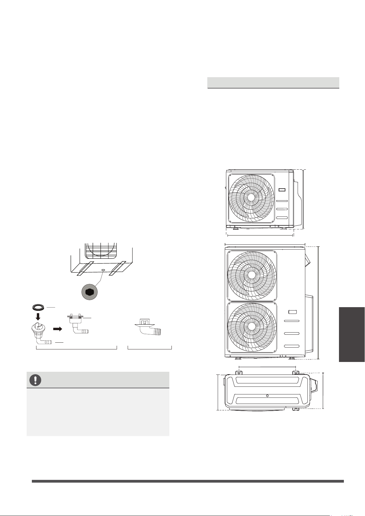
1. Indoor unit ...........................................................................................................................................................................08
2. Operating temperature...................................................................................................................................................09
3. Other features ....................................................................................................................................................................10
Installation Manual
Accessories............................................................................................16
Unit Parts...............................................................................................18
Indoor Unit Installation.......................................................................19
1. Select installation location.....................................................................................................................................................19
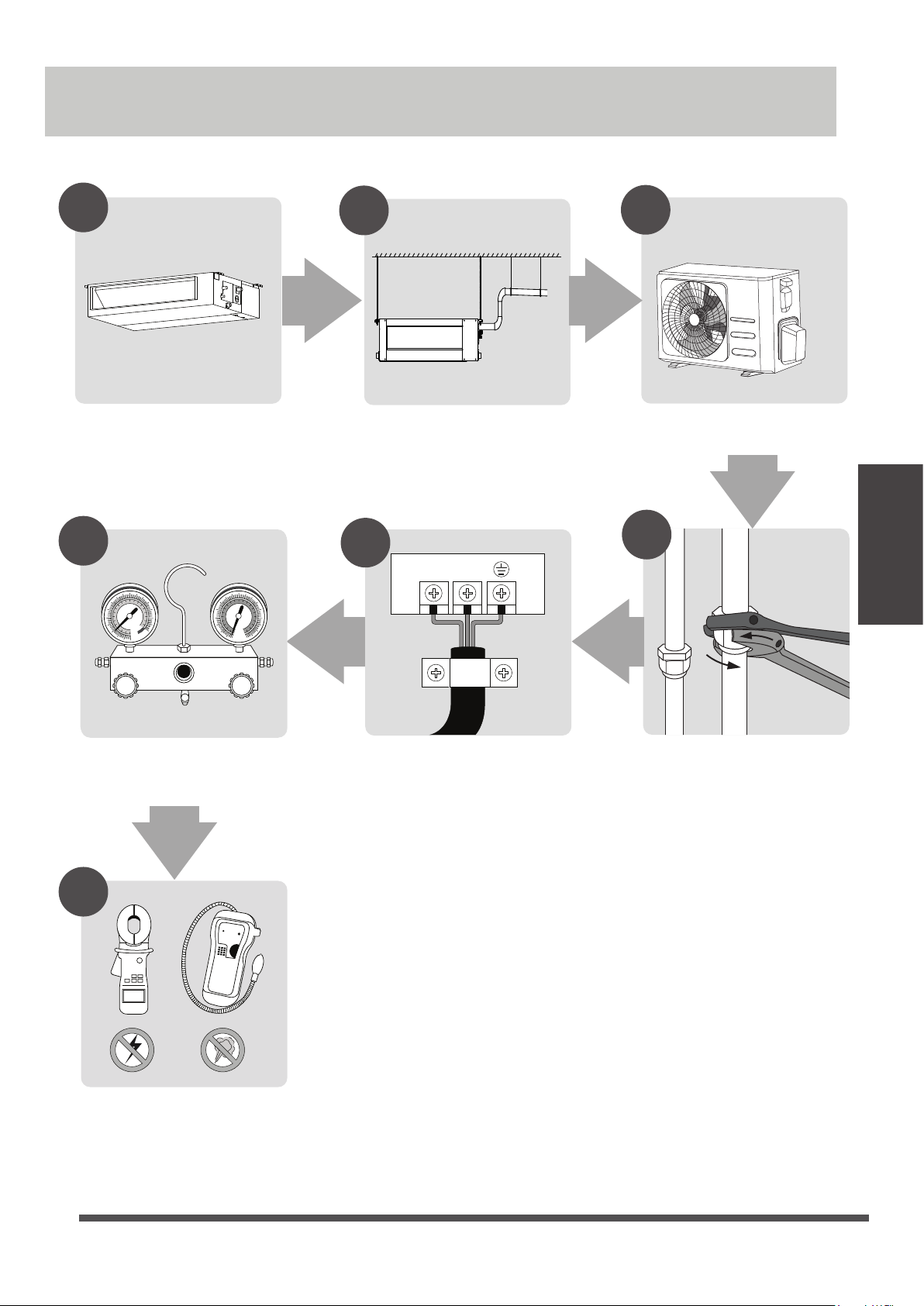
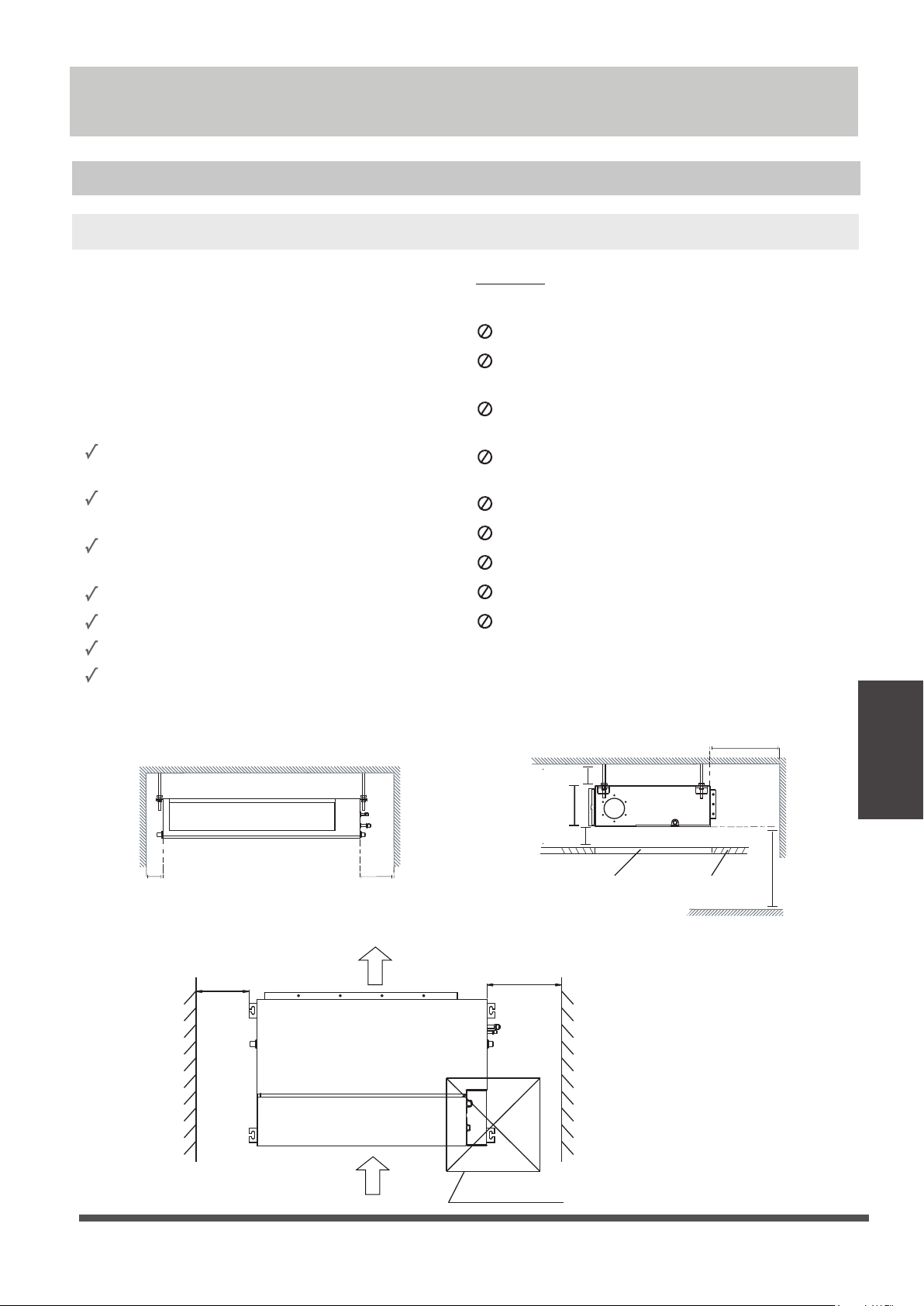
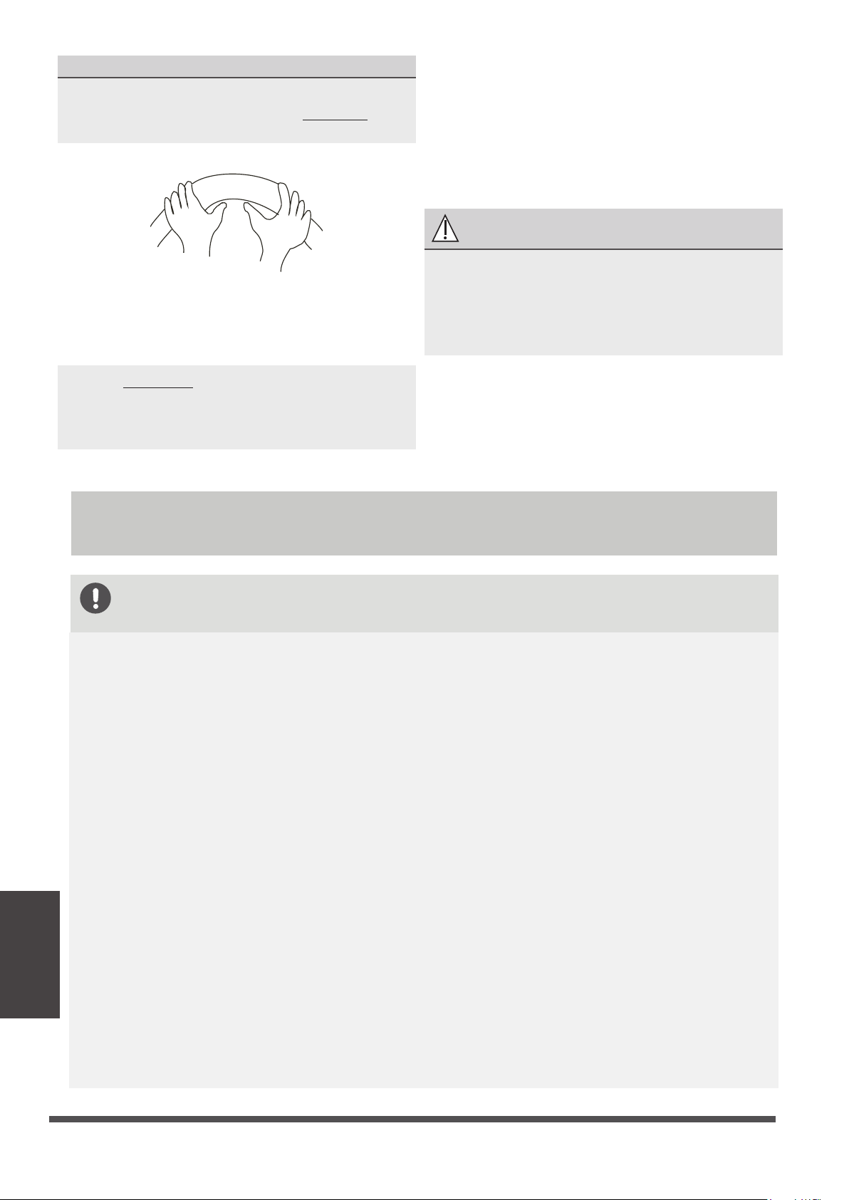
2. Hang indoor unit.......................................................................................................................................................................20
7. Drill wall hole for connective piping...................................................................................................................................23
8. Connect drain hose...................................................................................................................................................................24
Outdoor Unit Installation.........................................................................
.
26
1. Select installation location.....................................................................................................................................................26
2. Install drain joint........................................................................................................................................................................27
Wiring.........................................................................
...............................
32
1. Outdoor Uint Wiring.................................................................................................................................................................34
2. Indoor Uint Wiring....................................................................................................................................................................34
3. Power Specications................................................................................................................................................................35
3. Anchor outdoor unit................................................................................................................................................................27
Refrigerant Piping Connection...........................................................29
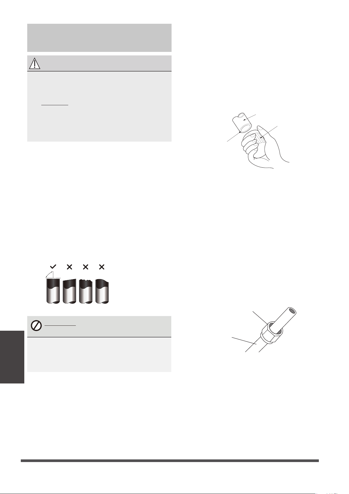
A. Note on Pipe Length................................................................................................................................................................29
B. Connection Instructions –Refrigerant Piping..................................................................................................................30
1. Cut pipe....................................................................................................................................................................................30
2. Remove burrs.........................................................................................................................................................................30
3. Flare pipe ends......................................................................................................................................................................31
4. Connect pipes........................................................................................................................................................................31
Air Evacuation.....................................................................................37
1. Evacuation Instructions...........................................................................................................................................................37
2. Note on Adding Refrigerant..................................................................................................................................................38
Test Run...............................................................................................39
Installation Summary...........................................................................17
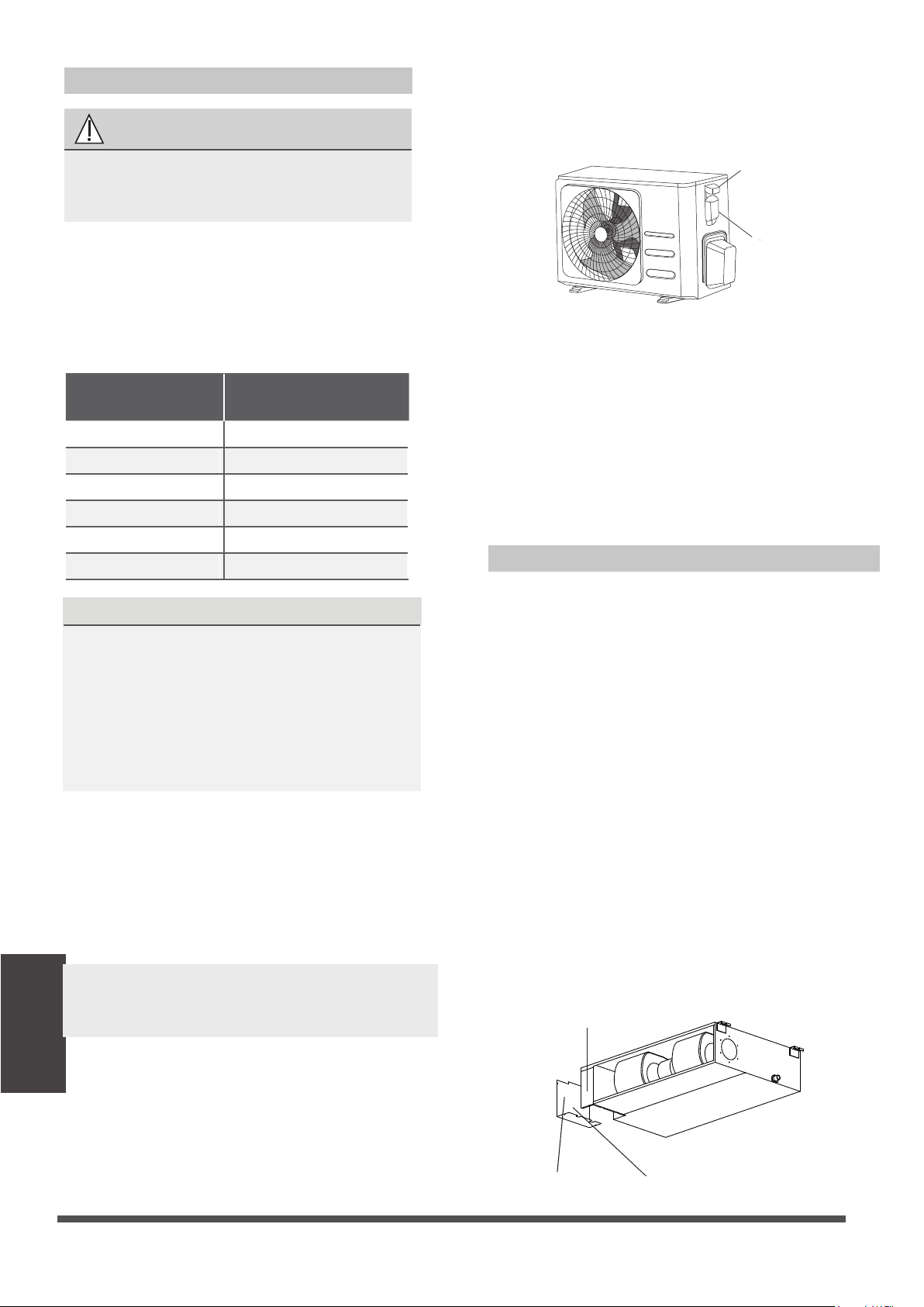
3. Duct and accessories installation.........................................................................................................................................22
4. Adjust the air inlet direction..................................................................................................................................................22
5. Fresh air duct installation........................................................................................................................................................23
6. Motor and drain pump maintenance.................................................................................................................................23
Read Safety Precautions Before Operation and Installation
The seriousness of potential damage or injuries is classified as either a WARNING or CAUTION.
Incorrect installation due to ignoring instructions can cause serious damage or injury.
WARNING
WARNINGS FOR PRODUCT USE
If an abnormal situation arises (like a burning smell), immediately turn o the unit and disconnect
the power. Call your dealer for instructions to avoid electric shock, re or injury.
Do not
insert fingers, rods or other objects into the air inlet or outlet. This may cause injury, since
the fan may be rotating at high speeds.
Do not
use flammable sprays such as hair spray, lacquer or paint near the unit. This may cause
re or combustion.
Do not
operate the air conditioner in places near or around combustible gases. Emitted gas may
collect around the unit and cause explosion.
Do not
Do not
expose your body directly to cool air for a prolonged period of time.
If the air conditioner is used together with burners or other heating devices, thoroughly ventilate
the room to avoid oxygen deficiency.
Safety Precautions
Do not
allow children to play with the air conditioner. Children must be supervised around the
unit at all times.
operate your air conditioner in a wet room such as a bathroom or laundry room. Too
much exposure to water can cause electrical components to short circuit.
In certain functional environments, such as kitchens, server rooms, etc., the use of specially
designed air-conditioning units is highly recommended.
WARNING
This symbol indicates the possibility
of personnel injury or loss of life.
CAUTION
This symbol indicates the possibility of
property damage or serious consequences.
Safety
Precautions
Page 4
This appliance can be used by children aged from 8 years and above and persons with reduced
This appliance is not intended for use by persons(including children) with reduced physical, sensory
or mental capabilities, or lack of experience and knowledge, unless they have been given
supervision or instruction concerning use of the appliance by a person responsible for their safety.
Children should be supervised to ensure that they do not play with the appliance.
physical, sensory or mental capabilities or lack of experience and knowledge if they have been given
supervision or instruction concerning use of the appliance in a safe way and understand the hazards
involved. Children shall not play with the appliance. Cleaning and user maintenance shall not be
made by children without supervision (EN Standard requirements).
CLEANING AND MAINTENANCE WARNINGS
CAUTION
Turn o the air conditioner and disconnect the power if you are not going to use it for a long time.
Turn o and unplug the unit during storms.
Make sure that water condensation can drain unhindered from the unit.
Do not
operate the air conditioner with wet hands. This may cause electric shock.
Do not
use device for any other purpose than its intended use.
Do not
climb onto or place objects on top of the outdoor unit.
Do not
allow the air conditioner to operate for long periods of time with doors or windows open,
or if the humidity is very high.
ELECTRICAL WARNINGS
Only use the specified power cord. If the power cord is damaged, it must be replaced by the
manufacturer
, its service agent or similarly qualied persons in order to avoid a hazard.
Keep power plug clean. Remove any dust or grime that accumulates on or around the plug. Dirty
plugs can cause re or electric shock.
Do not
pull power cord to unplug unit. Hold the plug firmly and pull it from the outlet. Pulling
directly on the cord can damage it, which can lead to fire or electric shock.
Do not
modify the length of the power supply cord or use an extension cord to power the unit.
Do not
share the electrical outlet with other appliances. Improper or insucient power supply
can cause re or electrical shock.
If connecting power to xed wiring, an all-pole disconnection device which has at least 3mm
clearances in all poles, and have a leakage current that may exceed 10mA, the residual current
device(RCD) having a rated residual operating current not exceeding 30mA, and disconnection
must be incorporated in the xed wiring in accordance with the wiring rules.
For all electrical work, follow all local and national wiring standards, regulations, and the
Installation Manual. Connect cables tightly, and clamp them securely to prevent external forces
from damaging the terminal. Improper electrical connections can overheat and cause re, and may
also cause shock.
All electrical connections must be made according to the Electrical Connection
Diagram located on the panels of the indoor and outdoor units.
All wiring must be properly arranged to ensure that the control board cover can close properly. If
the control board cover is not closed properly, it can lead to corrosion and cause the connection
points on the terminal to heat up, catch re, or cause electrical shock.
The product must be properly grounded at the time of installation, or electrical shock may occur.
TAKE NOTE OF FUSE SPECIFICATIONS
The air conditioner’s circuit board (PCB) is designed with a fuse to provide overcurrent protection.
The specifications of the fuse are printed on the circuit board ,such as :
T5A/250VAC, T10A/250VAC, etc.
T20A/250VAC(<=24000Btu/h units), T30A/250VAC(>24000Btu/h units)
NOTE: For the units with R-32 refrigerant , only the blast-proof ceramic fuse can be used.
Safety
Precautions
Page 5
Do not
clean the air conditioner with combustible cleaning agents. Combustible cleaning agents
can cause re or deformation.
Turn o the device and disconnect the power before cleaning. Failure to do so can cause
electrical shock.
Do not
clean the air conditioner with excessive amounts of water.
WARNINGS FOR PRODUCT INSTALLATION
1.
Installation must be performed by an authorized dealer or specialist. Defective installation can
cause water leakage, electrical shock, or fire.
2.
Installation must be performed according to the installation instructions. Improper installation
can cause water leakage, electrical shock, or fire.
3.
Contact an authorized service technician for repair or maintenance of this unit. This appliance
shall be installed in accordance with national wiring regulations.
4.
5.
6.
7.
8.
9.
10.
11.
Only use the included accessories, parts, and specied parts for installation. Using non-standard
parts can cause water leakage, electrical shock, re, and can cause the unit to fail.
Install the unit in a rm location that can support the unit’s weight. If the chosen location cannot
support the unit’s weight, or the installation is not done properly, the unit may drop and cause
serious injury and damage.
Install drainage piping according to the instructions in this manual. Improper drainage may
cause water damage to your home and property.
For units that have an auxiliary electric heater, do not install the unit within 1 meter of any
combustible materials.
Do not
install the unit in a location that may be exposed to combustible gas leaks. If
combustible
gas accumulates around the unit, it may cause re.
Do not turn on the power until all work has been completed.
When moving or relocating the air conditioner, consult experienced service technicians for
disconnection and reinstallation of the unit.
How to install the appliance to its support, please read the information for details in "indoor unit
installation" and "outdoor unit installation" sections .
Note about Fluorinated Gasses
1.
This air-conditioning unit contains fluorinated greenhouse gasses. For specic information on the
type of gas and the amount, please refer to the relevant label on the unit itself or
the
“Owner's Manual - Product Fiche ” in the packaging of the outdoor unit. (European
Union products only)
.
2.
Installation, service, maintenance and repair of this unit must be performed by a certified
technician.
3.
Product uninstallation and recycling must be performed by a certified technician.
4.
For equipment that contains uorinated greenhouse gases in quantities of 5 tonnes of CO
2
equivalent or more, but of less than 50 tonnes of CO
2
equivalent, If the system has a leak-
detection system installed, it must be checked for leaks at least every 24 months.
5.
When the unit is checked for leaks, proper record-keeping of all checks is strongly recommended.
Safety
Precautions
Page 6
WARNING for Using R-32 Refrigerant
When ammable refrigerant are employed, appliance shall be stored in a well -ventilated area
where the room size corresponds to the room area as specifiec for operation.
For R-32 frigerant models:
Appliance shall be installed, operated and stored in a room with a oor area larger than
X m²
.
Appliance shall not be installed in an unvertilated space, if that space is smaller than
X m²
(Please see the following form)
.
Reusable mechanical connectors and ared joints are not allowed indoors.
(EN Standard Requirements).
Mechanical connectors used indoors shall have a rate of not more than 3g/year at 25% of the
maximum allowable pressure. When mechanical connectors are reused indoors, sealing parts
shall be renewed. When ared joints are reused indoors, the are part shall be re-fabricated.
(UL Standard Requirements)
When mechanical connectors are reused indoors, sealing parts shall be renewed. When ared
joints are reused indoors, the are part shall be re-fabricated. (IEC Standard Requirements)
Mechanical connectors used indoors shall comply with ISO 14903.
Amount of refrigerant
to be charged (kg) Minimum room
area (m²)
1.11 1
1.65
2
≤2.58
5
≤3.08
7
≤3.84
10
≤4.24
Model
(Btu/h)
12000
18000
24000
30000
36000
42000-48000 12
≤4.39
60000 13
Safety
Precautions
Page 7
European Disposal Guidelines
This appliance contains refrigerant and other potentially hazardous materials. When disposing of
this appliance, the law requires special collection and treatment. Do not
dispose of this product as
household waste or unsorted municipal waste.
When disposing of this appliance, you have the following options:
Dispose of the appliance at designated municipal electronic waste collection facility.
When buying a new appliance, the retailer will take back the old appliance free of charge.
The manufacturer will take back the old appliance free of charge.
Sell the appliance to certied scrap metal dealers.
Special notice
Disposing of this appliance in the forest or other natural surroundings endangers your health and is bad
for the environment. Hazardous substances may leak into the ground water and enter the food chain.
Correct Disposal of This Product
(Waste Electrical & Electronic Equipment)
This marking shown on the product or its literature, indicates that waste electrical and eletrical
equipment should not be mixed with general household waste.
Unit Specifications and Features
Specifications
and Features
Indoor unit
Illustrations in this manual are for explanatory purposes. The actual shape of your indoor unit may be
slightly dierent. The actual shape shall prevail.
NOTE: Dierent models have dierent display panel. Not all the indicators describing below are available
for the air conditioner you purchased. Please check the indoor display panel of the unit you purchased.
This display panel on the indoor unit can be used to operate the unit in case the remote control has
been misplaced or is out of batteries.
Air outlet
Air inlet
Air filter(on some models)
Drain hose
Electric control cabinet
Refrigerant connecting pipe
(A) For the unit which the filter is removed for left or right side
Drain hose
Refrigerant connecting pipe
Air outlet
Air inlet
Air filter
(on some models)
(B) For the unit which the filter is removed from the bottom side
(C) For the unit which the filter is removed from the back
Page 8
screw
Air filter
1.Put the lter into the ange subassembly through the bottom side;
2.Lock the screw.
1. Remove two ange coaming;
2. Put the lter into the ange subassembly;
3. Rotate the air lter;
4. Put back to the ange coaming.
screw
Air filter(on some models)
Flange coaming
Unit
Specifications
and Features
MANUAL button :
This button selects the mode in the following order: AUTO, FORCED COOL, OFF.
FORCED COOL mode :
In FORCED COOL mode, the Operation light flashes. The system will then
turn to AUTO after it has cooled with a high wind speed for 30 minutes. The remote control will be
disabled during this operation.
OFF mode : When the display panel is turned OFF, the unit turns o and the remote control is
re-enabled.
Operating temperature
When your air conditioner is used outside of the following temperature ranges, certain safety
protection features may activate and cause the unit to disable.
COOL mode HEAT mode DRY mode
Room Temperature 17°C - 32°C 0°C - 30°C 10°C - 32°C
Outdoor
Temperature
0°C - 50°C
-15°C - 24°C 0°C - 50°C
0°C - 52°C
(For special
tropical models)
0°C - 52°C
(For special
tropical models)
-15°C - 50°C
(For models with
low temp.
cooling systems.)
Inverter Split Type
FOR OUTDOOR UNITS
WITH AUXILIARY
ELECTRIC HEATER
When outside
temperature is below 0°C,
we strongly recommend
keeping the unit plugged
in at all time to ensure
smooth ongoing
performance.
Display panel
Infrared
receiver
Timer
indicator
Alarm
indicator
PRE-DEF
(pre-heating/defrost)
indicator
Manual
button
Operation
indicator
LED display
Page 9
Unit
Specifications
and Features
To further optimize the performance of your unit, do the following:
Keep doors and windows closed.
Limit energy usage by using TIMER ON and TIMER OFF functions.
Do not block air inlets or outlets.
Regularly inspect and clean air lters.
NOTE: Room relative humidity less than 80%. If the air conditioner operates in excess of this
gure, the surface of the air conditioner may attract condensation. Please sets the vertical air
ow louver to its maximum angle (vertically to the oor), and set HIGH fan mode.
Room
Temperature 17°C-32°C 0°C-30°C 10°C-32°C
Outdoor
Temperature
18°C-43°C
-7°C-24°C
11°C-43°C
-7°C-43°C
(For models with low-temp cooling systems) 18°C-43°C
18°C-52°C
(For special tropical models) 18°C-52°C
(For special tropical models)
COOL mode HEAT mode DRY mode
Fixed-speed Type
Louver Angle Memory Function
(some models)
Some models are designed with a louver angle
memory function. When the unit restarts after a
power failure, the angle of the horizontal louvers
will automatically return to the previous position.
The angle of the horizontal louver should not be
set too small as condensation may form and drip
into the machine. To reset the louver, press the
manual button, which will reset the horizontal
louver settings.
Refrigerant Leak Detection System
(some models)
Other features
Default Setting
When the air conditioner restarts after a power
failure, it will default to the factory settings
(AUTO mode, AUTO fan, 24°C). This may cause
inconsistencies on the remote control and
unit panel. Use your remote control to update
the status.
Auto-Restart (some models)
In case of power failure, the system will
immediately stop. When power returns, the
Operation light on the indoor unit will flash. To
restart the unit, press the ON/OFF button on
the remote control. If the system has an auto
restart function, the unit will restart using the
same settings.
Three-minute protection feature
(some models)
A protection feature prevents the air
conditioner from being activated for
approximately 3 minutes when it restarts
immediately after operation.
Page10
The indoor unit will automatically display “EC”
or “EL0C”or ash LEDS (model dependent )
when it detects refrigerant leakage.
Care and Maintenance
Care and
Maintenance
Page 11
Cleaning Your Indoor Unit
BEFORE CLEANING OR
MAINTENANCE
ALWAYS TURN OFF YOUR AIR CONDITIONER
SYSTEM AND DISCONNECT ITS POWER SUPPLY
BEFORE CLEANING OR MAINTENANCE.
CAUTION
Only use a soft, dry cloth to wipe the unit clean.
If the unit is especially dirty, you can use a cloth
soaked in warm water to wipe it clean.
Do not
use chemicals or chemically treated
cloths to clean the unit
Do not use benzene, paint thinner,
polishing powder or other solvents to clean
the unit. They can cause the plastic surface
to crack or deform.
Do not use water hotter than 40°C to
clean the front panel. This can cause the
panel to deform or become discolored.
Cleaning Your Air Filter
A clogged air conditioner can reduce the cooling
efficiency of your unit, and can also be bad for
your health. Make sure to clean the filter once
every two weeks.
WARNING: DO NOT REMOVE OR
CLEAN THE FILTER BY YOURSELF
Removing and cleaning the filter can be
dangerous. Removal and maintenance must be
performed by a certified technician.
3. Remove the air lter.
4. Clean the air lter by vacuuming the surface
or washing it in warm water with mild
detergent.
5. Rinse the lter with clean water and allow it
to air-dry.
DO NOT
let the lter dry in direct
sunlight.
6. Reinstall the lter.
1. If the unit you purchased is a rear ventilated
one, take o the lter in the directions
indicated by the arrows in the following
diagram.
2. If the unit you purchased is a descending
ventilated model, take o the lter in the
directions indicated by the arrows in the
following diagram.
Rear ventilated model
or
or
or
Descending ventilated model
(A)
(B)
(C)
(A)
(B)
Care and
Maintenance
Page 12
Maintenance –
Long Periods of Non-Use
If you plan not to use your air conditioner for an
extended period of time, do the following:
Clean all lters Turn on FAN function until
unit dries out completely
Turn o the unit and
disconnect the power
Remove batteries
from remote control
Maintenance –
Pre-Season Inspection
After long periods of non-use, or before periods
of frequent use, do the following:
Check for damaged wires Clean all lters
Check for leaks Replace batteries
Make sure nothing is blocking all air inlets and outlets
If using a vacuum cleaner,
the inlet side should face
the vacuum.
If using water, the inlet side
should face down and away
from the water stream.
CAUTION
Before changing the lter or cleaning,
turn o the unit and disconnect its power
supply.
When removing lter, do not touch metal
parts in the unit. The sharp metal edges can
cut you.
Do not use water to clean the inside of the
indoor unit. This can destroy insulation and
cause electrical shock.
Do not expose lter to direct sunlight when
drying. This can shrink the lter.
CAUTION
Any maintenance and cleaning of outdoor
unit should be performed by an authorized
dealer or a licensed service provider.
Any unit repairs should be performed
by an authorized dealer or a licensed
service provider.
Troubleshooting
Common Issues
The following problems are not a malfunction and in most situations will not require repairs.
Issue Possible Causes
Unit does not turn
on when pressing
ON/OFF button
The Unit has a 3-minute protection feature that prevents the unit from overloading.
The unit cannot be restarted within three minutes of being turned o.
The unit may change its setting to prevent frost from forming on the unit.
Once the temperature increases, the unit will start operating in the
previously selected mode again.
The set temperature has been reached, at which point the unit turns o the
compressor. The unit will continue operating when the temperature
fluctuates again.
The indoor unit
emits white mist
In humid regions, a large temperature dierence between the room’s air
and the conditioned air can cause white mist.
Both the indoor and
outdoor units emit
white mist
When the unit restarts in HEAT mode after defrosting, white mist may be
emitted due to moisture generated from the defrosting process.
Troubleshooting
The unit changes from
COOL/HEAT mode to
FAN mode
The indoor unit makes
noises
A rushing air sound may occur when the louver resets its position.
A squeaking sound may occur after running the unit in HEAT mode due to
expansion and contraction of the unit’s plastic parts.
Both the indoor unit
and outdoor unit make
noises
Low hissing sound during operation: This is normal and is caused by refrigerant
gas flowing through both indoor and outdoor units.
Low hissing sound when the system starts, has just stopped running, or is
defrosting: This noise is normal and is caused by the refrigerant gas stopping or
changing direction.
Squeaking sound: Normal expansion and contraction of plastic and metal parts
caused by temperature changes during operation can cause squeaking noises.
SAFETY PRECAUTIONS
If any of the following conditions occurs, turn o your unit immediately!
The power cord is damaged or abnormally warm
You smell a burning odor
The unit emits loud or abnormal sounds
A power fuse blows or the circuit breaker frequently trips
Water or other objects fall into or out of the unit
DO NOT ATTEMPT TO FIX THESE YOURSELF! CONTACT AN AUTHORIZED
SERVICE PROVIDER IMMEDIATELY!
Cooling and Heating Models: If the Operation light and PRE-DEF (Pre-heating/
Defrost) indicators are lit up, the outdoor temperature is too cold and the unit’s
anti-cold wind is activated in order to defrost the unit.
In Cooling-only Models: If the “Fan Only” indicator is lit up, the outdoor
temperature is too cold and the unit’s anti-freeze protection is activated in
order to defrost the unit.
A squeaking sound is heard when the system is OFF or in COOL mode. The
noise is also heard when the drain pump (optional) is in operation.
Page 13
Troubleshooting
Issue Possible Causes
The outdoor unit
makes noises
The unit will make dierent sounds based on its current operating mode.
Dust is emitted from
either the indoor or
outdoor unit
The unit may accumulate dust during extended periods of non-use, which will be
emitted when the unit is turned on. This can be mitigated by covering the unit during
long periods of inactivity.
The unit emits a
bad odor
The unit may absorb odors from the environment (such as furniture, cooking,
cigarettes, etc.) which will be emitted during operations.
The unit’s filters have become moldy and should be cleaned.
The fan of the outdoor
unit does not operate
During operation, the fan speed is controlled to optimize product operation.
NOTE: If problem persists, contact a local dealer or your nearest customer service center. Provide
them with a detailed description of the unit malfunction as well as your model number.
Troubleshooting
When troubles occur, please check the following points before contacting a repair company.
Problem Possible Causes Solution
Poor Cooling
Performance
Temperature setting may be higher
than ambient room temperature Lower the temperature setting
The heat exchanger on the indoor
or outdoor unit is dirty
Clean the aected heat exchanger
The air lter is dirty Remove the filter and clean it according to
instructions
The air inlet or outlet of either
unit is blocked
Turn the unit o, remove the obstruction
and turn it back on
Doors and windows are open Make sure that all doors and windows are
closed while operating the unit
Excessive heat is generated
by sunlight
Close windows and curtains during periods
of high heat or bright sunshine
Too many sources of heat in the
room (people, computers,
electronics, etc.)
Reduce amount of heat sources
Low refrigerant due to leak
or long-term use
Check for leaks, re-seal if necessary and
top o refrigerant
Page 14
Troubleshooting
Problem Possible Causes Solution
The unit is not
working
Power failure Wait for the power to be restored
The power is turned o Turn on the power
The fuse is burned out Replace the fuse
Remote control batteries are dead
Replace batteries
The Unit’s 3-minute protection
has been activated
Wait three minutes after restarting
the unit
Timer is activated Turn timer o
The unit starts and
stops frequently
There’s too much or too little
refrigerant in the system
Check for leaks and recharge the
system with refrigerant.
Incompressible gas or moisture
has entered the system.
Evacuate and recharge the system
with refrigerant
The compressor is broken Replace the compressor
The voltage is too high or
too low Install a manostat to regulate the
voltage
Poor heating
performance
The outdoor temperature is
extremely low
Use auxiliary heating device
Cold air is entering through
doors and windows Make sure that all doors and
windows are closed during use
Low refrigerant due to leak or
long-term use Check for leaks, re-seal if necessary
and top o refrigerant
Indicator lamps
continue flashing The unit may stop operation or continue to run safely. If the indicator
lamps continue to flash or error codes appear, wait for about 10
minutes. The problem may resolve itself.
If not, disconnect the power, then connect it again. Turn the unit on.
If the problem persists, disconnect the power and contact your nearest
customer service center.
Error code appears and
begins with the letters
as the following in the
window display of
indoor unit:
E(x), P(x), F(x)
EH(xx), EL(xx), EC(xx)
PH(xx), PL(xx), PC(xx)
NOTE:
If your problem persists after performing the checks and diagnostics above,
turn o your unit immediately and contact an authorized service center.
System circuit is blocked Determine which circuit is blocked and
replace the malfunctioning piece of
equipment
Page 15
Accessories
Manual
Name
Shape Quantity(PC)
Parts you must purchase
separately. Consult the dealer
about the proper pipe size of
the unit you purchased.
Connecting pipe
assembly
Liquid side
Gas side
Φ6.35(1/4 in)
Φ9.52(3/8in)
Φ12.7(1/2in)
Φ9.52(3/8in)
Φ12.7(1/2in)
Φ 16(5/8in)
Φ 19(3/4in)
Φ 22(7/8in)
2~4
2
Name of Accessories
Q‘ty(pc) Shape
1
1
1
1
Name of Accessories
Q‘ty(pc) Shape
Soundproof/insulation
sheath
Drain joint
(some models)
Seal ring
(some models)
Magnetic ring (wrap
the electric wires S1
& S2 ( P & Q & E )
around the magnetic
ring twice)
(some models)
Magnetic ring (Hitch
it on the connective
cable between indoor
unit and outdoor unit
after installation.)
(some models)
S1&S2(P&Q&E)
Copper nut 2
Accessories
Orifice
(some models)
1
1
1
Transfer connector
(Φ
Φ
12.7-Φ
Φ
15.9)
(some models)
Transfer connector
(Φ
Φ
6.35-Φ
Φ
9.52)
(some models)
Transfer connector
(Φ
Φ
9.52-Φ
Φ
12.7)
(some models)
Connecting wire for
display (2m)
(some models)
Cord protection
rubber ring
(some models)
Display panel
*Just for testing
purposes only
( some models-
KJR-120G,KJR-120H)
1
1
1
Optional accessories
There are two types of remote controls: wired and wireless.
Select a remote controller based on customer preferences and requirements and install in an
appropriate place.
Refer to catalogues and technical literature for guidance on selecting a suitable remote controller.
The air conditioning system comes with the following accessories. Use all of the installation parts and
accessories to install the air conditioner. Improper installation may result in water leakage, electrical
shock and re, or cause the equipment to fail. The items are not included with the air conditioner must
be purchased separately.
Page 16
Varies
by model
Perform a test run
Installation Summary
Install the outdoor unitInstall the drainpipe
123
4
5
MC MC
6
Install the indoor unit
Evacuate the
refrigeration system Connect the wires Connect the
refrigerant pipes
7
Installation Summary
Page 17
L(L1) N(L2)
Unit Parts
NOTE ON ILLUSTRATIONS
Illustrations in this manual are for explanatory purposes. The actual shape of your indoor
unit may be slightly dierent. The actual shape shall prevail.
NOTE: The installation must be performed in accordance with the requirement of local and
national standards. The installation may be slightly dierent in dierent areas.
Unit Parts
Drain pipe
Connecting pipe
Air inlet
Air outlet
Air outlet
Air inlet
1
2
3
4
5
6
6
7
1
2
3
4
5
6
7
Electric control cabinet
Or
Page 18
Indoor Unit
Installation
Installation Instructions – Indoor unit
Indoor Unit Installation
NOTE: Panel installation should be performedafter piping and wiring have been completed.
Step 1: Select installation location
Before installing the indoor unit, you must
choose an appropriate location. The following
are standards that will help you choose an
appropriate location for the unit.
Proper installation locations meet the
following standards:
DO NOT install unit in the following
locations:
Areas with oil drilling or fracking
Coastal areas with high salt content in the
air
Areas with caustic gases in the air, such as
hot springs
Areas that experience power uctuations,
such as factories
Enclosed spaces, such as cabinets
Kitchens that use natural gas
Areas with strong electromagnetic waves
Areas that store flammable materials or gas
Rooms with high humidity, such as
bathrooms or laundry rooms
Enough room exists for installation and
maintenance.
Enough room exists for the connecting the
pipe and drainpipe.
The ceiling is horizontal and its structure can
sustain the weight of the indoor unit.
The air inlet and outlet are not blocked.
The airflow can fill the entire room.
There is no direct radiation from heaters.
Models with a cooling capacity of 9000Btu to
18000Btu only apply to one room.
Maintenance space
Installation place
Left
side
Right
side
Strong and durable ceiling
Indoor unit
>7.9in(20cm) >11.8in(30cm)
>0.8in(2cm)
>0.8in(2cm)
>11.8in(30cm)
>90.6in(230cm)
Floor
Service access Ceiling
(When no ceiling)
B
Air outlet
Air inlet
7.9in(20cm) 11.8in(30cm)
23.6inx23.6in(60cmx60cm)
checking orice
Page 19
Indoor Unit
Installation
Step 2: Hang indoor unit.
1. Please refer to the following diagrams to locate the four positioning screw bolt holes on the
ceiling. Be sure to mark the paces where you will drill ceiling hook holes.
Air outlet dimensions
Air inlet dimensions
Descending ventilation opening and mounted hook
Air lter
Electric control box
(unit: mm/inch)
MODEL
(Btu/h)
Outline dimension
A B C
18K 210/8.3 674/26.5880/34.6
24K~36K 249/9.8 774/30.51100/43.3
30K~36K 249/9.8 774/30.51360/53.5
36K~60K 300/11.8 874/34.41200/47.2
air outlet opening size
D E F
136/5.4 706/27.8600/23.6
175/6.9 926/36.5700/27.6
175/6.9 1186/46.7700/27.6
227/8.9 1044/41.1800/31.5
air return opening size
190/7.5
228/8.9
228/8.9
280/11
Size of mounted lug
I
920/36.2782/30.8
1140/44.91001/39.4
1400/55.11261/49.6
1240/48.81101/43.3
J
G
H
508/20
598/23.5
598/23.5
697/27.4
Air lter
9K/12K 200/7.9 506/19.9700/27.6 152/6 537/21.1450/17.7 186/7.3 741/29.2599/23.6
360/14.2
Page 20
Indoor Unit
Installation
Cut o the roof beam.
Strengthen the point at which the cut was
made. Consolidate the roof beam.
Original concrete bricks
Use an embedding screw bolt, crock, and stick
harness.
Steel roof beam structure
Install and use the supporting steel angle.
Wood
Place the wood mounting across the roof beam,
then install the hanging screw bolts.
Wood mounting
Roof beam
Hanging screw bolts
Ceiling
New concrete bricks
Inlay or embed the screw bolts.
(Blade shape insertion) (Slide insertion)
Steel bar
Embedding screw bolt
(Pipe hanging and embedding screw bolt)
Hanging screw bolt
Hanging
bolts
Supporting
angle steel
Screw nut
Washer
Hanging screw bolt
Overhang part
Shockproof cushion
NOTE:
Confirm the minimum drain tilt is
1/100 or more.
CAUTION
The unit body must be completely aligned
with the hole. Ensure that the unit and the
hole arethe same size before moving on.
2. Install and t pipes and wires after you have
nished installing the main body.When
choosing where to start, determine the
direction of the pipes to be drawn out.
Especially in cases where there is a ceiling
involved, align the refrigerant pipes, drain
pipes, and indoor and outdoor lines with their
connection points before mounting the unit.
3. Install hanging screw bolts.
4. After you select an installation location,align
the refrigerant pipes, drain pipes, as well as
indoor and outdoor wires with their
connection points before mounting the unit.
5. Drill 4 holes 10cm (4”) deep at the ceiling
hook positions in the internal ceiling. Be sure
to hold the drill at a 90° angle to the ceiling.
6. Secure the bolt using the washers and nuts
provided.
7. Install the four suspension bolts.
8. Mount the indoor unit with at least two
people to lift and secure it. Insert suspension
bolts into the unit’s hanging holes. Fasten
them using the washers and nuts provided.
9. Mount the indoor unit onto the hanging
screw bolts with a block. Position the indoor
unit at using a level indicator to prevent
leaks.
Page 21
MODEL
(Btu/h)
Static Pressure
(Pa/in.wg)
0~100/0~0.4
18K
0~160/0~0.64
24K
0~160/0~0.64
30K~36K
0~160/0~0.64
42K~60K
0~50/0~0.2
9K
0~50/0~0.2
12K
Indoor Unit
Installation
Step 4: Adjust the air inlet direction
(From rear side to under-side)
Step 3: Duct and accessories installation
NOTE:
1. Do not place the connecting duct weight on
the indoor unit.
2.When connecting the duct, use an
nonammable canvas tie-in to prevent
vibrating.
3.Insulation foam must be wrapped outside
the duct to avoid condensate. An internal
duct underlayer can be added to reduce
noise, if the end-user requires.
1. Install the lter (optional) according to the size
of the air inlet.
5. Refer to the following static pressure guidelines
when installing the indoor unit.
Change the fan motor static pressure
according to external duct static pressure.
2. Install the canvas tie-in between the body and
duct.
3. The air inlet and air outlet duct should be far
enough apart enough to a avoid air passage
short-circuit.
4. Connect the duct according to the following
diagram:
Canvas tie-in Canvas tie-in
Air outlet Isolation booth
Isolation booth
checking orice
Air inlet
Air dust lter
Page 22
1. Take o the ventilation panel and ange.
2. Change the mounting positions of the
ventilation panel and air return ange.
Air return ange
Ventilation panel
3. When installing the lter mesh, t it into the
ange as illustrated in the following gure.
NOTE: All the gures in this manual are for
demonstration purposes only. The air
conditioner you have purchased may be
slightly dierent in design, though similar in
shape.
Air return ange
Ventilation panel
Air return ange
Ventilation panel
Or
Bend the rear ventilation panel 90 degrees
along the dotted line into a descending
ventilation panel.(some models)
Indoor Unit
Installation
Step 7: Drill wall hole for connective piping
1.
Determine the location of the wall hole
based on the location of the outdoor unit.
2.
Using a 65mm (2.5in) or 90mm(3.54in)
(depending on models )core drill, drill a
hole in the wall. Make sure that the hole
is drilled at
a slight downward angle, so
that the outdoor end of the hole is lower
than the indoor end by about 12mm (0.5in).
This will ensure proper water drainage.
3.
Place the protective wall cu in the hole. This
protects the edges of the hole and will help
seal it when you nish the installation process.
CAUTION
When drilling the wall hole, make sure to
avoid wires, plumbing, and other sensitive
components.
Wall
IndoorOutdoor
≈ 12mm / 0.5 inch
Step 5: Fresh air duct installation
Dimension : Duct joint for fresh air
Ø92mm(3.62”) Ø113mm(4.45”)
MODLE
9-12
Ø125mm(4.92”) Ø160mm(6.3”)
MODLE
18-60
Step 6: Motor and drain pump maintenance
Motor maintenance:
Take o the ventilated panel.
Take o the blower housing.
Take o the motor.
1.
2.
3.
(the rear ventilated panel is used as an example)
Pump maintainance:
Remove four screws from the drain pump.
Unplug the pump power supply and water
level switch cable.
Detach the pump.
1.
2.
3.
Pump
Motor
Blower housing
Ventilated panel
Page 23
Indoor Unit
Installation
Step 8: Connect drain hose
The drainpipe is used to drain water away from
the unit. Improper installation may cause unit
and property damage.
CAUTION
Insulate all piping to prevent condensation,
which could lead to water damage.
If the drainpipe is bent or installed
incorrectly, water may leak and cause a
water-level switch malfunction.
In HEAT mode, the outdoor unit will
discharge water. Ensure that the drain hose
is placed in an appropriate area to avoid
water damage and slippage.
DO NOT pull the drainpipe forcefully. This
could disconnect it.
NOTE ON PURCHASING PIPES
Installation requires a polyethylene tube
(exterior diameter = 3.7-3.9cm, interior
diameter = 3.2cm), which can be obtained at
your localhardware store or dealer.
Indoor Drainpipe Installation
Install the drainpipe as illustrated in the following
Figure.
1.
2.
Drainpipe
connecting port
Drain hose
Pipe clasp Insulation
Cover the drainpipe with heat insulation to
prevent condensation and leakage.
Attach the mouth of the drain hose to the
unit’s outlet pipe. Sheath the mouth of the
hose and clip it rmly with a pipe clasp.
(39-59”)
1-1.5m1-1
Lean over 1/50
Ceiling
(39-59”)
(7.9”)
<20cm
(21.7”)
<55cm
Lean over 1/50
1-1.5m1-1
Drainpipe installation for units with a pump
Ceiling
NOTE ON DRAINPIPE INSTALLATION
When using an extended drainpipe,
tightenthe indoor connection with an
additionalprotection tube. This prevents
it from pulling loose.
The drainpipe should slope downward at a
gradient of at least 1/100 to prevent water
from flowing back into the air conditioner.
To prevent the pipe from sagging, space
hanging wires every 1-1.5m (39-59”).
If the outlet of the drainpipe is higher than
the body’s pump joint, use a lift pipe for
the indoor unit’s exhaust outlet. The lift
pipe must be installed no higher than
55cm (21.7”) from the ceiling board. The
distance between the unit and the lift pipe
must be less than 20cm (7.9”). Incorrect
installation could cause water to ow back
into the unit and ood.
NOTE: When connecting multiple drainpipes,
install the pipes as illustrated.
To prevent air bubbles, keep the drain
hose level or slightly tiled up (<75mm / 3”).
≥10cm
(4”)
Units with a pump
Units without a pump
Page 24
0-55cm
(21.7”)
Indoor Unit
Installation
Drainage test
Check whether the drainpipe is unhindered.
This test should be performed on newly built
houses before the ceiling is paved.
Units with a pump.
Units without a pump.
1. Remove the test cover.
Fill the water pan with 2 liters of water.
2. Turn on the unit in COOLING mode. You will
hear the drain pump.Check whether the
water is discharged properly (a 1-minute lag
is possible, depending on the length of the
drain pipe), Check whether water leaks from
the joints.
3. Turn o the air conditioner and put the cap
back on.
3. Pass the drain hose through the wall hole.
Make sure the water drains to a safe location
where it will not cause water damage or a
slipping hazard.
NOTE: The drainpipe outlet should be at least
5cm (1.9”) above the ground. If it touches the
ground, the unit may become blocked and
malfunction. If you discharge the water directly
into a sewer, make sure that the drain has a U
or S pipe to catch odors that might otherwise
come back into the house.
Test cap
C
L
O
S
E
D
O
P
E
N
C
L
O
S
E
D
O
P
E
N
Stow tube
Stow tube
Fill the water pan with 2 liters of water.
Check that the drainpipe is unhindered.
Page 25
Outdoor Unit
Installation
evoba )ni42( mc06
60cm (24in)
on right
30cm (12in)
on left
200cm (79in)
in front
30cm (12in)
from back wall
Installation Instructions – Outdoor unit
Step 1: Select installation location
Before installing the outdoor unit, you must
choose an appropriate location. The following are
standards that will help you choose an appropriate
location for the unit.
Proper installation locations meet the
following standards:
Meets all spatial requirements shown in
Installation Space Requirements above.
Good air circulation and ventilation
Firm and solid—the location can support
the unit and will not vibrate
Noise from the unit will not disturb others
Install the unit by following local codes and
regulations , there may be dier slightly
between dierent regions.
SPECIAL CONSIDERATIONS FOR
EXTREME WEATHER
If the unit is exposed to heavy wind:
Install unit so that air outlet fan is at a 90°
angle to the direction of the wind. If needed,
build a barrier in front of the unit to protect it
from extremely heavy winds.
See Figures below.
Strong
wind
Strong wind
Strong wind
If the unit is frequently exposed to heavy
rain or snow:
Build a shelter above the unit to protect
it from the rain or snow. Be careful not to
obstruct air flow around the unit.
If the unit is frequently exposed to salty air
(seaside):
Use outdoor unit that is specially designed to
resist corrosion.
Wind Baffle
Protected from prolonged periods of direct
sunlight or rain
DO NOT
install unit in the following locations:
Near an obstacle that will block air inlets
and outlets
Near a public street, crowded areas, or
where noise from the unit will disturb others
Near animals or plants that will be harmed
by hot air discharge
Near any source of combustible gas
In a location that is exposed to large
amounts of dust
In a location exposed to a excessive amounts
of salty air
Where snowfall is anticipated, raise the
unit above the base pad to prevent ice
buildup and coil damage. Mount the unit
high enough to be above the average
accumulated area snowfall. The minimum
height must be 18 inches
Outdoor Unit Installation
Page 26
Indoor Unit
Outdoor Unit
Installation
Page 27
Step 2: Install drain joint(Heat pump unit only)
Before bolting the outdoor unit in place, you must
install the drain joint at the bottom of the unit.
Note that there are two dierent types of drain
joints depending on the type of outdoor unit.
If the drain joint comes with a rubber seal
(see Fig. A ), do the following:
1.
Fit the rubber seal on the end of the drain joint
that will connect to the outdoor unit.
2.
Insert the drain joint into the hole in the base
pan of the unit.
3.
Rotate the drain joint 90° until it clicks in place
facing the front of the unit.
4.
Connect a drain hose extension (not included)
to the drain joint to redirect water from the
unit during heating mode.
If the drain joint doesn’t come with a rubber
seal (see Fig. B ), do the following:
1.
Insert the drain joint into the hole in the base
pan of the unit. The drain joint will click in
place.
2.
Connect a drain hose extension (not included)
to the drain joint to redirect water from the
unit during heating mode.
Seal
Drain joint
(A) (B)
Base pan hole of
outdoor unit
Seal
IN COLD CLIMATES
In cold climates, make sure that the drain
hose is as vertical as possible to ensure
swift water drainage. If water drains too
slowly, it can freeze in the hose and ood
the unit.
The outdoor unit can be anchored to the
ground or to a wall-mounted bracket with
bolt(M10). Prepare the installation base of
the unit according to the dimensions below.
Step 3: Anchor outdoor unit
UNIT MOUNTING DIMENSIONS
The following is a list of dierent outdoor
unit sizes and the distance between their
mounting feet. Prepare the installation
base of the unit according to the
dimensions below.
Split Type Outdoor Unit
A
B
D
W
H
W
H
Outdoor Unit Types and Specifications
Indoor Unit
Outdoor Unit
Installation
Page 28
(unit: mm/inch)
Outdoor Unit Dimensions
W x H x D
Mounting Dimensions
Distance A Distance B
760x590x285 (29.9x23.2x11.2) 530 (20.85) 290 (11.4)
810x558x310 (31.9x22x12.2) 549 (21.6) 325 (12.8)
845x700x320 (33.27x27.5x12.6) 560 (22) 335 (13.2)
900x860x315 (35.4x33.85x12.4) 590 (23.2) 333 (13.1)
945x810x395 (37.2x31.9x15.55) 640 (25.2) 405 (15.95)
990x965x345 (38.98x38x13.58) 624 (24.58) 366 (14.4)
946x810x420 (37.24x31.9x16.53) 673 (26.5) 403 (15.87)
946x810x410 (37.24x31.9x16.14) 673 (26.5) 403 (15.87)
952x1333x410 (37.5x52.5x16.14) 634 (24.96) 404 (15.9)
952x1333x415 (37.5x52.5x16.34) 634 (24.96) 404 (15.9)
845x702x363 (33.27x27.6x14.3) 540 (21.26) 350 (13.8)
938x1369x392 (36.93x53.9x15.43) 634 (24.96) 404 (15.9)
900x1170x350 (35.4x46x13.8) 590 (23.2) 378 (14.88)
800x554x333 (31.5x21.8x13.1) 514 (20.24) 340 (13.39)
890x673x342 (35x26.5x13.46) 663 (26.1) 354 (13.94)
Rows of series installation
L H L 1/2H
L A
25 cm / 9.8” or more
1/2H < L H
30 cm / 11.8” or more
L > H Can not be installed
The relations between H, A and L are as follows.
L
H
300 cm / 118” or more
A
60 cm / 23.6”
or more
150 cm / 59”
or more
25 cm / 9.8”
or more
25 cm / 9.8”
or more
Refrigerant Piping Connection
Refrigerant piping
Connection
Page 29
Note on Pipe Length
When connecting refrigerant piping, do not let substances or gases other than the specied
refrigerant enter the unit. The presence of other gases or substances will lower the unit’s capacity,
and can cause abnormally high pressure in the refrigeration cycle. This can cause explosion and
injury.
Ensure that the length of the refrigerant pipe, the number of bends, and the drop height
between the indoor and outdoor units meets the requirements shown in the following table :
The Maximum Length And Drop Height Based on Models. (Unit: m/ft.)
Type of model Capacity (Btu/h) Length of piping Maximum drop height
EU frequency
conversion Split
Type
<15K 25/82 10/32.8
15K - <24K 30/98.4 20/65.6
24K - <36K 50/164 25/82
36K - 60K 65/213 30/98.4
Other Split Type
12K 15/49 8/26
18K-24K 25/82 15/49
30K-36K 30/98.4 20/65.6
42K-60K 50/164 30/98.4
Oil traps
CAUTION
If oil flows back into the outdoor unit’s
compressor, this might cause liquid
compression or deterioration of oil return.
Oil traps in the rising gas piping can prevent
this.
An oil trap should be installed every 6m(20ft)
of vertical suction line riser
(36000Btu/h unit).
An oil trap should be installed every
10m(32.8ft) of vertical suction line riser
(≥36000Btu/h unit).
10m/32.8ft
(≥36000Btu/h unit)
6m/20ft
(36000Btu/h unit)
10m/32.8ft
(≥36000Btu/h unit)
6m/20ft
(36000Btu/h unit)
Indoor unit/
Outdoor unit
Indoor unit/
Outdoor unit
Refrigerant piping
Connection
Page 30
Step 3: Flare pipe ends
Proper aring is essential to achieve an airtight
seal.
1.
After removing burrs from cut pipe, seal
the ends with PVC tape to prevent foreign
materials from entering the pipe.
2.
Sheath the pipe with insulating material.
3.
Place are nuts on both ends of pipe.
Make sure they are facing in the right
direction, because you can’t put them on
or change their direction after flaring.
Flare nut
Copper pipe
4.
Remove PVC tape from ends of pipe when
ready to perform aring work.
2.
Using a reamer or deburring tool, remove
all burrs from the cut section of the pipe.
Pipe
Reamer
Point down
Connection Instructions –
Refrigerant Piping
Step 1: Cut pipes
When preparing refrigerant pipes, take extra
care to cut and flare them properly. This will
ensure efficient operation and minimize the
need for future maintenance.
1. Measure the distance between the indoor
and outdoor units.
2. Using a pipe cutter, cut the pipe a little longer
than the measured distance.
3. Make sure that the pipe is cut at a perfect 90°
angle.
Oblique Rough Warped
90°
DO NOT DEFORM PIPE
WHILE CUTTING
Be extra careful not to damage, dent, or
deform the pipe while cutting. This will
drastically reduce the heating eciency
of the unit.
CAUTION
The branching pipe must be installed
horizontally. An angle of more than 10° may
cause malfunction.
DO NOT install the connecting pipe until
both indoor and outdoor units have been
installed.
Insulate both the gas and liquid piping to
prevent water leakage.
Step 2: Remove burrs.
Burrs can aect the air-tight seal of refrigerant
piping connection. They must be completely
removed.
1.
Hold the pipe at a downward angle to
prevent burrs from falling into the pipe.
Refrigerant piping
Connection
Page 31
5.
Clamp are form on the end of the pipe.
The end of the pipe must extend beyond
the are form.
Flare form
Pipe
6.
Place aring tool onto the form.
7.
Turn the handle of the aring tool
clockwise until the pipe is fully ared. Flare
the pipe in accordance with the dimensions.
PIPING EXTENSION BEYOND FLARE FORM
8. Remove the aring tool and are form,
then inspect the end of the pipe for cracks
and even aring.
Step 4: Connect pipes
Connect the copper pipes to the indoor unit rst,
then connect it to the outdoor unit. You should
rst connect the low-pressure pipe, then the high-
pressure pipe.
1.
When connecting the are nuts, apply a
thin coat of refrigeration oil to the ared
ends of the pipes.
2. Align the center of the two pipes that you
will connect.
Indoor unit tubing Flare nut Pipe
3.
Tighten the are nut as tightly as possible
by hand.
4.
Using a spanner, grip the nut on the unit
tubing.
5. While rmly gripping the nut, use a torque
wrench to tighten the are nut according
to the torque values in above table.
NOTE: Use both a spanner and a torque wrench
when connecting or disconnecting pipes to/from
the unit.
Pipe
gauge Tightening
torque Flare dimension (A)
(Unit: mm/Inch) Flare shape
Min. Max.
Ø 6.35
R0.4~0.8
45°±2
90 °
±4
A
Ø 9.52
Ø 12.7
Ø 16
Ø 19
Ø 22
65-67 N.m
(663-683 kgf.cm) 23.2/0.91 23.7/0.93
75-85N.m
(765-867 kgf.cm) 26.4/1.04 26.9/1.06
18-20 N.m
(183-204 kgf.cm) 8.4/0.33 8.7/0.34
25-26 N.m
(255-265 kgf.cm) 13.2/0.52 13.5/0.53
35-36 N.m
(357-367 kgf.cm) 16.2/0.64 16.5/0.65
45-47 N.m
(459-480 kgf.cm) 19.2/0.76 19.7/0.78
CAUTION
Ensure to wrap insulation around the piping.
Direct contact with the bare piping may
result in burns or frostbite.
Make sure the pipe is properly connected.
Over tightening may damage the bell mouth
and under tightening may lead to leakage.
BEFORE PERFORMING ANY ELECTRICAL WORK, READ THESE
REGULATIONS
1. All wiring must comply with local and national electrical codes, regulations and must be
installed by a licensed electrician.
2. All electrical connections must be made according to the Electrical Connection Diagram located
on the panels of the indoor and outdoor units.
3. If there is a serious safety issue with the power supply, stop work immediately. Explain your
reasoning to the client, and refuse to install the unit until the safety issue is properly resolved.
4. Power voltage should be within 90-110% of rated voltage. Insucient power supply can cause
malfunction, electrical shock, or re.
5. If connecting power to xed wiring, a surgeprotector and main power switch should be
installed.
6. If connecting power to xed wiring, a switch or circuit breaker that disconnects all poles and
has a contact separation of at least 1/8in (3mm) must be incorporated in the xed wiring. The
qualied technician must use an approved circuit breaker or switch.
7. Only connect the unit to an individual branch circuit outlet. Do not connect another appliance
to that outlet.
8. Make sure to properly ground the air conditioner.
9. Every wire must be rmly connected. Loose wiring can cause the terminal to overheat,
resulting in product malfunction and possible re.
10. Do not let wires touch or rest against refrigerant tubing, the compressor, or any moving parts
within the unit.
11. If the unit has an auxiliary electric heater, it mustbe installed at least 1 meter (40in) away from
any combustible materials.
Wiring
Wiring
Page 32
NOTE ON MINIMUM BEND RADIUS
Carefully bend the tubing in the middle
according to the diagram below. DO NOT bend
the tubing more than 90° or more than 3 times.
Bend the pipe with thumb
min-radius 10cm (3.9”)
6.
After connecting the copper pipes to the indoor
unit, wrap the power cable, signal cable and the
piping together with binding tape.
NOTE: DO NOT intertwine signal cable with
other wires. While bundling these items
together, do not intertwine or cross the signal
cable with any other wiring.
7. Thread this pipeline through the wall and
connect it to the outdoor unit.
8. Insulate all the piping, including the valves of
the outdoor unit.
9. Open the stop valves of the outdoor unit to
start the ow of the refrigerant between the
indoor and outdoor unit.
CAUTION
Check to make sure there is no refrigerant leak
after completing the installation work. If there is
a refrigerant leak, ventilate the area immediately
and evacuate the system (refer to the Air
Evacuation section of this manual).
Wiring
Page 33
13. Make sure that you do not cross your
electrical wiring with your signal wiring.
This may cause distortion and
interference.
14. The unit must be connected to the
main outlet. Normally, the power supply
must have a impedance of 32 ohms.
15. No other equipment should be
connected to the same power circuit.
16. Connect the outdoor wires before
connecting the indoor wires.
WARNING
BEFORE PERFORMING ANY
ELECTRICAL OR WIRING WORK,
TURN OFF THE MAIN POWER TO
THE SYSTEM.
NOTE ON AIR SWITCH
When the maximum current of the air
conditioner is more than 16A, an air switch
or leakage protection switch with protective
device shall be used(purchased seperately) .
When the maximum current of the air
conditioner is less than 16A, the power cord
of air conditioner shall be equipped with
plug (purchased seperately) .
12.To avoid getting an electric shock, never
touch the electrical components soon
after the power supply has been turned
o. After turning o the power, always
wait 10 minutes or more before you touch
the electrical components.
NOTE: The cographs are for explanation
purpose only. Your machine may be
slightly dierent. The actual shape shall
prevail.
Indoor unit
Outdoor unit
Air switch
(purchased seperately)
Air switch
(purchased seperately)
Indoor unit power wires
Indoor & Outdoor
connective wires
Indoor unit
Outdoor unit
Air switch
(purchased seperately)
Outdoor unit power wires
Indoor unit
Outdoor unit
Air switch
(purchased seperately)
Indoor unit power wires
Indoor & Outdoor
connective wires
Indoor & Outdoor
connective wires
(A)
(B)
(C)
Wiring
Using a wire crimper, crimp u-lugs on the
ends.
b. Using wire strippers, strip the rubber
jacketfrom both ends of the signal cable
to reveal approximately 15cm (5.9”) of
wire.
c. Strip the insulation from the ends.
d.
NOTE: When connecting the wires, strictly
follow the wiring diagram found inside the
electrical box cover.
2. Remove the electric cover of the outdoor unit.
If there is no cover on the outdoor unit, take
o the bolts from the maintenance board
and remove the protection board.
Outdoor Unit Wiring
WARNING
Before performing any electrical or wiring
work, turn o the main power to the
system.
1. Prepare the cable for connection
a. You must rst choose the right cable
size. Be sure to use H07RN-F cables.
Cover
Screw
Indoor Unit Wiring
3. Connect the u-lugs to the terminals
Match the wire colors/labels with the labels
on the terminal block. Firmly screw the u-lug
of each wire to its corresponding terminal.
4. Clamp down the cable with the cable clamp.
5. Insulate unused wires with electrical tape.
Keep them away from any electrical or metal
parts.
6. Reinstall the cover of the electric control box.
1. Prepare the cable for connection.
a. Using wire strippers, strip the rubber jacket
from both ends of the signal cable to reveal
about 15cm (5.9”) of the wire.
b. Strip the insulation from the ends of the
wires.
c. Using a wire crimper, crimp the u-lugs to
the ends of the wires.
2. Remove the cover of the electric control box
on your indoor unit.
3. Connect the u-lugs to the terminals.
Match the wire colors/labels with the labels
on the terminal block. Frmly screw the
u-lug of each wire to its corresponding
terminal. Refer to the Serial Number and
Wiring Diagram located on the cover of the
electric control box.
Connective wiring diagramWiring diagram
Control box
Page 34
Minimum Cross-Sectional Area of
Power and Signal Cables (For reference)
Rated Current of
Appliance (A)
Nominal Cross-Sectional
Area (mm²)
> 3 and 6 0.75
> 6 and 10 1
> 10 and 16 1.5
> 16 and 25 2.5
> 25 and 32 4
> 32 and 40 6
CHOOSE THE RIGHT CABLE SIZE
The size of the power supply cable, signal cable,
fuse, and switch needed is determined by the
maximum current of the unit. The maximum
current is indicated on the nameplate located
on the side panel of the unit. Refer to this
nameplate to choose the right cable, fuse, or
switch.
Wiring
Magnetic ring
(if supplied and packed with the
accessories)
1 2 3
Pass the belt through
the hole of the Magnetic
ring to fix it on the cable
Page 35
4. Clamp down the cable with the cable clamp.The
cable must not be loose or pull on the u-lugs.
5. Reattach the electric box cover.
Power Specifications
NOTE: Electric auxiliary heating type circuit breaker/fuse need to add more than 10 A.
Indoor Power Supply Specifications
MODEL
(Btu/h)
18K 19K~24K 25K~36K 37K~48K 49K~60K
POWER
PHASE 1 Phase 1 Phase 1 Phase 1 Phase 1 Phase
VOLT
VOLT
VOLT
VOLT
208-240V 208-240V 208-240V 208-240V 208-240V
CIRCUIT BREAKER/
FUSE(A) 25/20 32/25 50/40 70/55 70/60
MODEL
(Btu/h)
36K 37K~60K 36K 37K~60K
POWER
PHASE 3 Phase 3 Phase 3 Phase 3 Phase
380-420V 380-420V 208-240V 208-240V
CIRCUIT BREAKER/FUSE(A) 25/20 32/25 32/25 45/35
MODEL
(Btu/h)
18K 19K~24K 25K~36K 37K~48K 49K~60K
POWER
PHASE 1 Phase 1 Phase 1 Phase 1 Phase 1 Phase
208-240V 208-240V 208-240V 208-240V 208-240V
CIRCUIT BREAKER/
FUSE(A) 25/20 32/25 50/40 70/55 70/60
MODEL
(Btu/h)
36K 37K~60K 36K 37K~60K
POWER
PHASE 3 Phase 3 Phase 3 Phase 3 Phase
380-420V 380-420V 208-240V 208-240V
CIRCUIT BREAKER/FUSE(A) 25/20 32/25 32/25 45/35
Outdoor Power Supply Specifications
CAUTION
While connecting the wires, please strictly follow
the wiring diagram.
The refrigerant circuit can become very hot.
Keep the interconnection cable away from the
copper tube.
Wiring
Page 36
VOLT
VOLT
VOLT
VOLT
VOLT
VOLT
VOLT
VOLT
Independent Power Supply Specifications
MODEL
(Btu/h)
18K 19K~24K 25K~36K 37K~48K 49K~60K
POWER
(indoor)
PHASE 1 Phase 1 Phase 1 Phase 1 Phase 1 Phase
208-240V 208-240V 208-240V208-240V 208-240V
CIRCUIT BREAKER/
FUSE(A) 15/10 15/10 15/10 15/10 15/10
POWER
(outdoor)
PHASE 1 Phase 1 Phase 1 Phase 1 Phase 1 Phase
208-240V 208-240V 208-240V
208-240V208-240V
CIRCUIT BREAKER/
FUSE(A) 25/20 32/25 50/40 70/55 70/60
MODEL
(Btu/h)
18K 19K~24K 25K~36K 37K~48K 49K~60K
POWER
(indoor)
PHASE 1 Phase 1 Phase 1 Phase 1 Phase 1 Phase
220-240V 220-240V 220-240V220-240V 220-240V
CIRCUIT BREAKER/
FUSE(A) 15/10 15/10 15/10 15/10 15/10
POWER
(outdoor)
PHASE 1 Phase 1 Phase 1 Phase 1 Phase 1 Phase
208-240V 208-240V 208-240V
208-240V208-240V
CIRCUIT BREAKER/
FUSE(A) 25/20 25/20 40/30 50/40 50/40
MODEL
(Btu/h)
36K 37K~60K 36K 37K~60K
POWER
(indoor)
PHASE 1 Phase 1 Phase 1 Phase 1 Phase
208-240V 208-240V 208-240V 208-240V
CIRCUIT BREAKER/FUSE(A) 15/10 15/10 15/10 15/10
POWER
(outdoor)
PHASE 3 Phase 3 Phase 3 Phase 3 Phase
380-420V 380-420V 208-240V 208-240V
CIRCUIT BREAKER/FUSE(A) 25/20 32/25 32/25 45/35
MODEL
(Btu/h)
36K 37K~60K 36K 37K~60K
POWER
(indoor)
PHASE 1 Phase 1 Phase 1 Phase 1 Phase
220-240V 220-240V 220-240V 220-240V
CIRCUIT BREAKER/FUSE(A) 15/10 15/10 15/10 15/10
POWER
(outdoor)
PHASE 3 Phase 3 Phase 3 Phase 3 Phase
380-420V 380-420V 208-240V 208-240V
CIRCUIT BREAKER/FUSE(A) 25/20 32/25 32/25 40/30
Inverter Type A/C Power Specifications
Preparations and Precautions
Air and foreign matter in the refrigerant circuit can
cause abnormal rises in pressure, which can damage
the air conditioner, reduce its efficiency, and cause
injury. Use a vacuum pump and manifold gauge to
evacuate the refrigerant circuit, removing any
non-condensable gas and moisture from the system.
Evacuation should be performed upon initial
installation and when unit is relocated.
BEFORE PERFORMING EVACUATION
Check to make sure the connective pipes
between the indoor and outdoor units
are connected properly .
Check to make sure all wiring is connected
properly.
Evacuation Instructions
Manifold Gauge
Compound
gauge
-76cmHg
Low pressure
valve
High pressure
valve
Pressure hose /
Charge hose
Charge hose
V
acuum
pump
Pressure gauge
Low pressure valve
1.
Connect the charge hose of the manifold
gauge to service port on the outdoor unit’s
low pressure valve.
Connect another charge hose from the
manifold gauge to the vacuum pump.
Open the Low Pressure side of the manifold
gauge. Keep the High Pressure side closed.
Turn on the vacuum pump to evacuate the
system.
Run the vacuum for at least 15 minutes, or
until the Compound Meter reads -76cmHG
(-10
5
Pa).
2.
3.
4.
5.
6.
Close the Low Pressure side of the manifold
gauge, and turn o the vacuum pump.
7.
Wait for 5 minutes, then check that there
has been no change in system pressure.
8.
If there is a change in system pressure, refer
to Gas Leak Check section for information
on how to check for leaks. If there is no
change in system pressure, unscrew the cap
from the packed valve (high pressure valve).
9.
Insert hexagonal wrench into the packed valve
(high pressure valve) and open the valve by
turning the wrench in a 1/4 counterclockwise
turn. Listen for gas to exit the system, then
close the valve after 5 seconds.
10.
Watch the Pressure Gauge for one minute
to make sure that there is no change in
pressure. The Pressure Gauge should read
slightly higher than atmospheric pressure.
Flare nut
Cap
valve body valve stem
11.
Remove the charge hose from the service port.
12.
Using hexagonal wrench, fully open both the
high pressure and low pressure valves.
13.
Tighten valve caps on all three valves (service
port, high pressure, low pressure) by hand.
You may tighten it further using a torque
wrench if needed.
OPEN VALVE STEMS GENTLY
When opening valve stems, turn the hexagonal
wrench until it hits against the stopper. Do not
try to force the valve to open further.
Air Evacuation
Air Evacuation
Page 37
Air Evacuation
Note on Adding Refrigerant
Some systems require additional charging depending on pipe lengths. The standard pipe length varies
according to local regulations. In other areas, the standard pipe length is 5m (16‘). The refrigerant
should be charged from the service
port
on the outdoor unit’s low pressure valve.
The additional
refrigerant to be charged can be calculated using the following formula:
Liquid Side Diameter
R-32 : (Total pipe length -
standard pipe length)x
12g(0.13oZ)/m(ft)
(Total pipe length -
standard pipe length)x
24g(0.26oZ)/m(ft)
(Total pipe length -
standard pipe length)x
40g(0.42oZ)/m(ft)
φ6.35(1/4”) φ9.52(3/8”) φ12.7(1/2”)
Page 38
Test Run
Test Run
Before Test Run
A test run must be performed after the entire
system has been completely installed. Confirm
the following points before performing the test:
a) Indoor and outdoor units are properly
installed.
b) Piping and wiring are properly connected.
c) No obstacles near the inlet and outlet of
the unit that might cause poor performance
or product malfunction.
d) Refrigeration system does not leak.
e) Drainage system is unimpeded and
draining to a safe location.
f) Heating insulation is properly installed.
g) Grounding wires are properly connected.
h) Length of the piping and additional
refrigerant stow capacity have been
recorded.
i) Power voltage is the correct voltage
for the air conditioner.
CAUTION
Failure to perform the test run may result in
unit damage, property damage, or personal
injury.
Test Run Instructions
1. Open both the liquid and gas stop valves.
2. Turn on the main power switch and allow the
unit to warm up.
3. Set the air conditioner to COOL mode.
4. For the Indoor Unit
a. Ensure the remote control and its buttons
work properly.
b. Ensure the louvers move properly and can
be changed using the remote control.
c. Double check to see if the room
temperature is being registered correctly.
d. Ensure the indicators on the remote
control and the display panel on the indoor
unit work properly.
e. Ensure the manual buttons on the indoor
unit works properly.
f. Check to see that the drainage system is
unimpeded and draining smoothly.
g. Ensure there is no vibration or abnormal
noise during operation.
5. For the Outdoor Unit
a. Check to see if the refrigeration system is
leaking.
b. Make sure there is no vibration or
abnormal noise during operation.
c. Ensure the wind, noise, and water
generated by the unit do not disturb your
neighbors or pose a safety hazard.
6. Drainage Test
a. Ensure the drainpipe flows smoothly. New
buildings should perform this test before
finishing the ceiling.
b. Remove the test cover. Add 2,000ml of
water to the tank through the attached
tube.
c. Turn on the main power switch and run
the air conditioner in COOL mode.
d. Listen to the sound of the drain pump to
see if it makes any unusual noises.
e. Check to see that the water is discharged.
It may take up to one minute before the
unit begins to drain depending on the
drainpipe.
f. Make sure that there are no leaks in any of
the piping.
g. Stop the air conditioner. Turn o the main
power switch and reinstall the test cover.
NOTE: If the unit malfunctions or does not
operate according to your expectations,
please refer to the Troubleshooting section
of the Owner’s Manual before calling
customer service.
Page 39
QS001UI-T2
16123000001933
20200710
The design and specifications are subject to change without prior notice for
product improvement. Consult with the sales agency or manufacturer for details.
Any updates to the manual will be uploaded to the service website, please check
for the latest version.
3

Hulp nodig? Stel uw vraag in het forum

Spelregels

Misbruik melden

Gebruikershandleiding.com neemt misbruik van zijn services uitermate serieus. U kunt hieronder aangeven waarom deze vraag ongepast is. Wij controleren de vraag en zonodig wordt deze verwijderd.

Product:

Bijvoorbeeld antisemitische inhoud, racistische inhoud, of materiaal dat gewelddadige fysieke handelingen tot gevolg kan hebben.

Bijvoorbeeld een creditcardnummer, een persoonlijk identificatienummer, of een geheim adres. E-mailadressen en volledige namen worden niet als privégegevens beschouwd.

Spelregels forum

Om tot zinvolle vragen te komen hanteren wij de volgende spelregels:

Belangrijk! Als er een antwoord wordt gegeven op uw vraag, dan is het voor de gever van het antwoord nuttig om te weten als u er wel (of niet) mee geholpen bent! Wij vragen u dus ook te reageren op een antwoord.

Belangrijk! Antwoorden worden ook per e-mail naar abonnees gestuurd. Laat uw emailadres achter op deze site, zodat u op de hoogte blijft. U krijgt dan ook andere vragen en antwoorden te zien.

Abonneren

Abonneer u voor het ontvangen van emails voor uw Frigicoll KPD-71 DR13 bij:


U ontvangt een email met instructies om u voor één of beide opties in te schrijven.


Ontvang uw handleiding per email

Vul uw emailadres in en ontvang de handleiding van Frigicoll KPD-71 DR13 in de taal/talen: Engels als bijlage per email.

De handleiding is 3.78 mb groot.


U ontvangt de handleiding per email binnen enkele minuten. Als u geen email heeft ontvangen, dan heeft u waarschijnlijk een verkeerd emailadres ingevuld of is uw mailbox te vol. Daarnaast kan het zijn dat uw internetprovider een maximum heeft aan de grootte per email. Omdat hier een handleiding wordt meegestuurd, kan het voorkomen dat de email groter is dan toegestaan bij uw provider.

Stel vragen via chat aan uw handleiding

Stel uw vraag over deze PDF

Andere handleiding(en) van Frigicoll KPD-71 DR13

Frigicoll KPD-71 DR13 Gebruiksaanwijzing - Nederlands - 44 pagina's

Frigicoll KPD-71 DR13 Gebruiksaanwijzing - Deutsch - 44 pagina's


Uw handleiding is per email verstuurd. Controleer uw email

Als u niet binnen een kwartier uw email met handleiding ontvangen heeft, kan het zijn dat u een verkeerd emailadres heeft ingevuld of dat uw emailprovider een maximum grootte per email heeft ingesteld die kleiner is dan de grootte van de handleiding.

Er is een email naar u verstuurd om uw inschrijving definitief te maken.

Controleer uw email en volg de aanwijzingen op om uw inschrijving definitief te maken

U heeft geen emailadres opgegeven

Als u de handleiding per email wilt ontvangen, vul dan een geldig emailadres in.

Uw vraag is op deze pagina toegevoegd

Wilt u een email ontvangen bij een antwoord en/of nieuwe vragen? Vul dan hier uw emailadres in.


Info