o - fast continuous 0 % - 100 % - 0 % ramping (15 seconds)
n - slow ramp in 25 % steps (15 seconds/step)
p - fast ramp in 25 % steps (5 seconds/step)
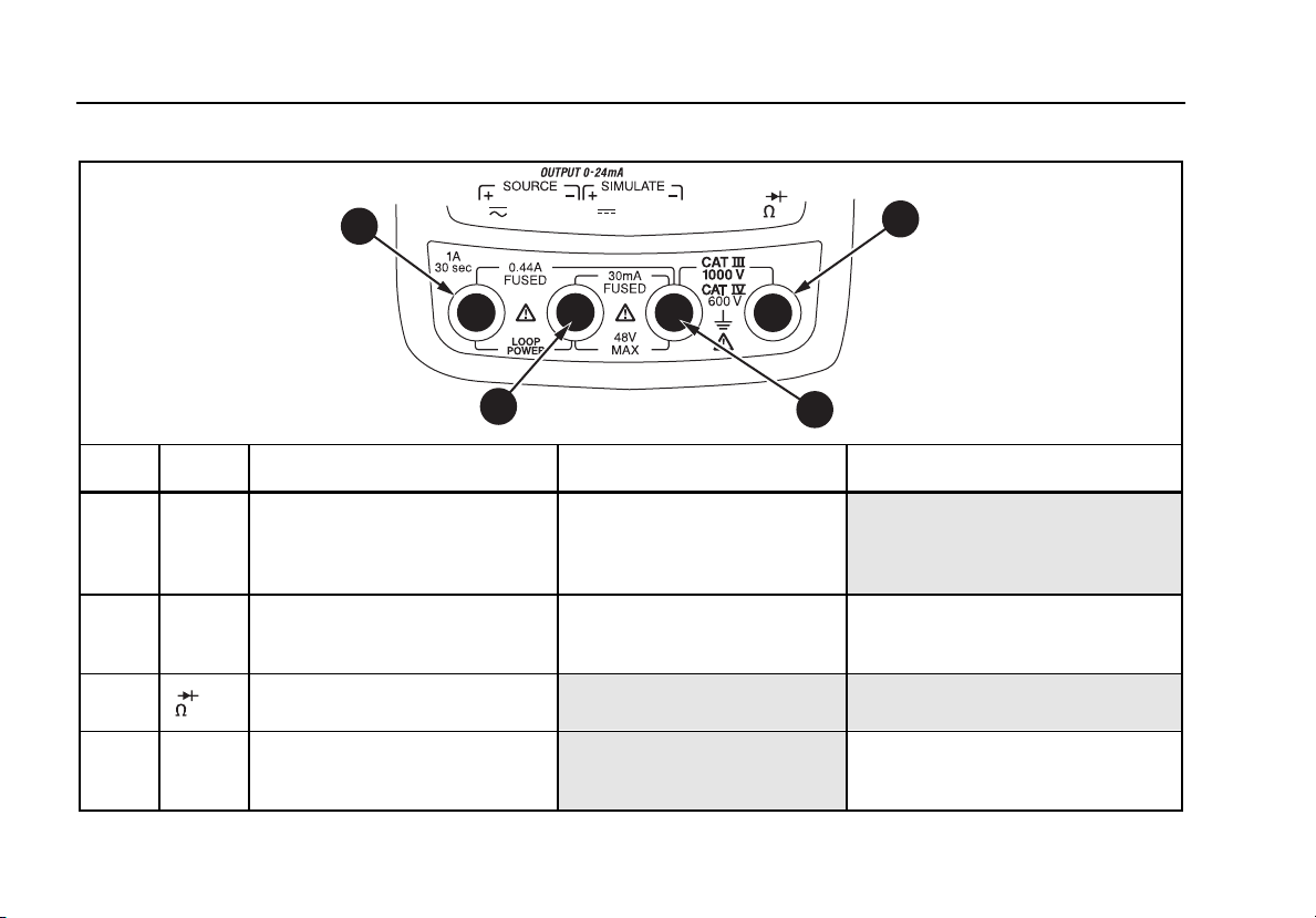
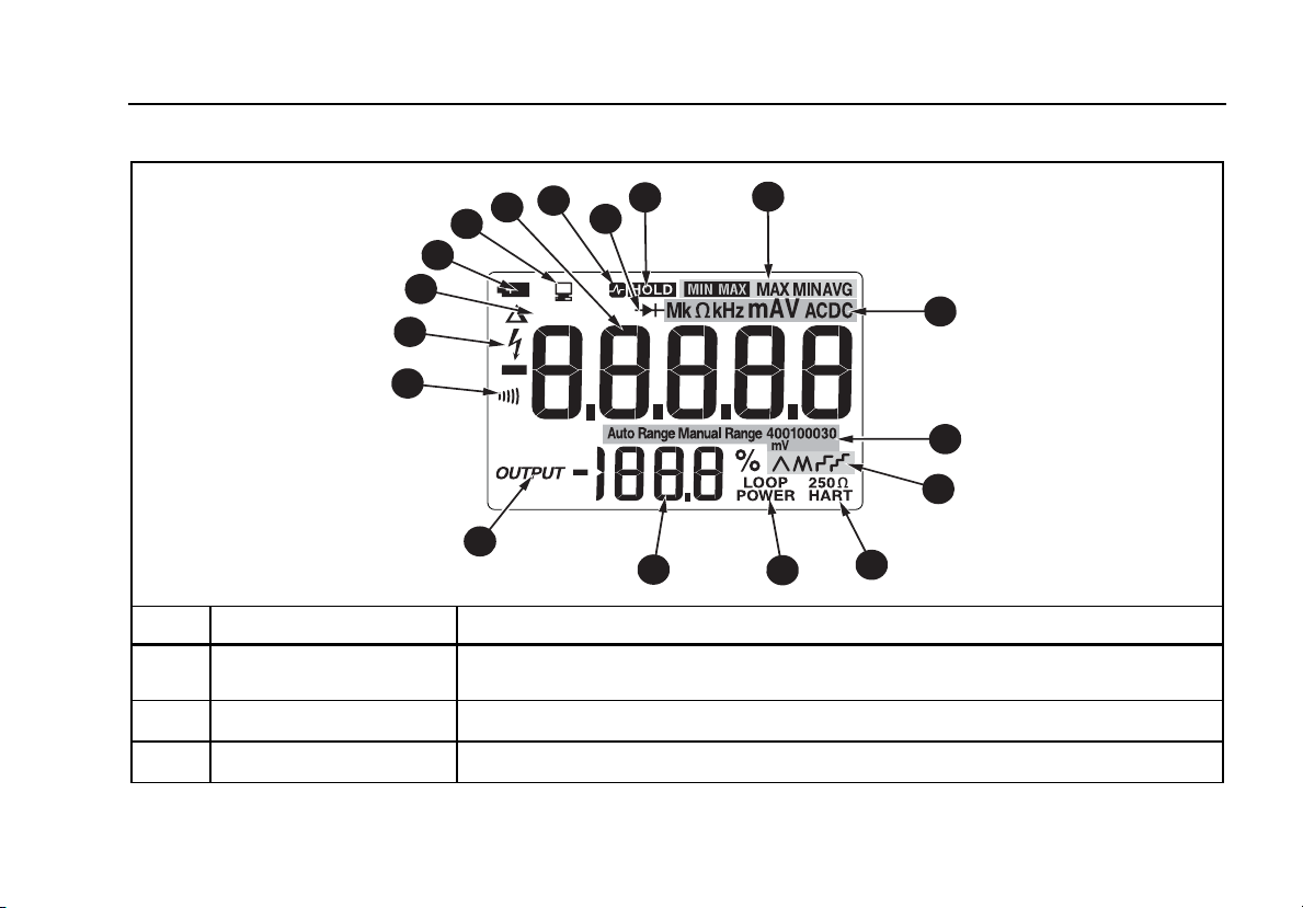
250 Ω
HART Lights when 250 Ω series resistance is switched in (789 only)
Loop Power Lights when in loop supply mode (789 only)
789/787B
Users Manual
18
Measuring Electrical Parameters
The proper sequence for taking measurements is:
1. Plug the test leads into the appropriate jacks.
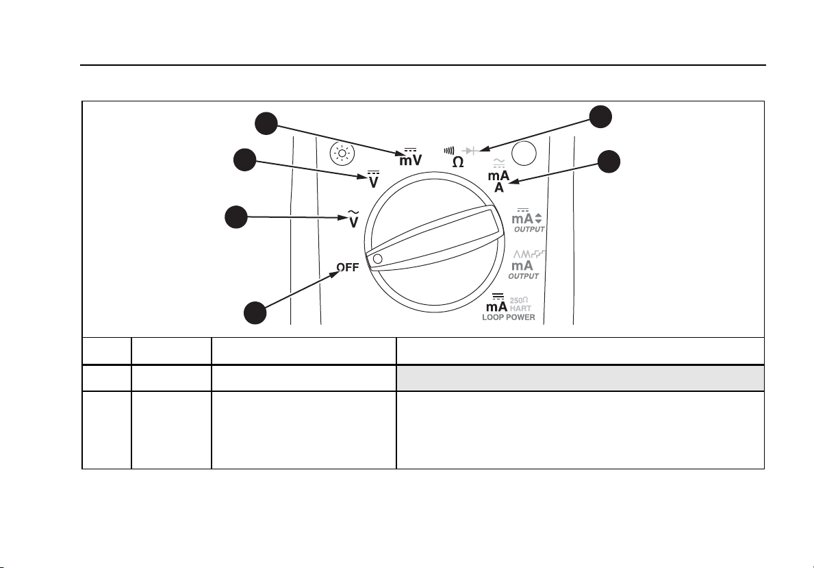
2. Set the rotary function switch to the desired function.
3. Touch the probes to the test points.
4. View the results on the LCD display.
Input Impedance
For the voltage measurement functions, input impedance
is 10 MΩ. See "Specifications" for more information.
Ranges
A measurement range determines the highest value and
resolution at which the meter can measure. Most meter
measurement functions have more than one range (see
"Specifications").
Make sure the correct range is selected:
•If the range is too low, the display shows OL
(overload).
•If the range is too high, the meter will not be
displaying its most precise measurement.
The meter normally selects the lowest range that will
measure the applied input signal (Auto Range showing on
the display). Press R to lock the range. Each time
R is pressed, the meter selects the next higher range.
At the highest range, it returns to the lowest range.
If the range is locked, the meter resumes auto ranging
when it is changed to another measurement function or
when R is pressed and held for 1 second.
Testing Diodes
To test a single diode:
1. Insert the red test lead into the Vjack and
black test lead into the COM jack.
2. Set the rotary function switch to V.
3. Press J (Blue) so that the D symbol is on the
display.
4. Touch the red probe to the anode and the black
probe to the cathode (side with band or bands). The
meter should indicate the appropriate diode voltage
drop.
5. Reverse the probes. The meter displays OL,
indicating high impedance.
The diode is good if it passes the tests in steps 4
and 5.
ProcessMeter™
Measuring Electrical Parameters
19
Displaying Minimum, Maximum, and Average
MIN MAX recording stores the lowest and highest
measurements, and maintains the average of all
measurements.
Press M to turn on MIN MAX recording. Readings are
stored until the meter is turned off, switched to another
measurement or source function, or MIN MAX is turned
off. The beeper sounds when a new maximum or
minimum is recorded. Auto power-off is disabled and auto
ranging is turned off during MIN MAX recording.
Press M again to cycle through the MAX, MIN, and
AVG displays. Press and hold M for 1 second to erase
stored measurements and exit.
In MIN MAX recording, press H to suspend recording;
press H again to resume recording.
Using AutoHold
Note
MIN MAX recording must be off to use AutoHold.
! Warning
To avoid possible electric shock, do not use
AutoHold to determine if dangerous voltage
is present. AutoHold will not capture
unstable or noisy readings.
Activate AutoHold to freeze the meter's display on each
new stable reading (except in the frequency counter
mode). Press H to activate AutoHold. This feature
allows measurements to be taken in situations in which it
is difficult to look at the display. The meter beeps and
updates the display with each new stable reading.
789/787B
Users Manual
20
Compensating for Test Lead Resistance
Use the relative reading feature (Q on the display) to set
the present measurement as a relative zero. A common
use for this feature is to compensate for test lead
resistance when measuring ohms.
Select the Ω measure function, touch the test leads
together, and then press r. Until r is pressed
again, or the meter is switched to another measurement
or source function, the readings on the display will
subtract the lead resistance.
Using the Current Output Functions
The meter provides steady, stepped, and ramped current
output for testing 0-20 mA and 4-20 mA current loops.
Choose source mode, in which the meter supplies the
current, simulate mode, in which the meter regulates
current in an externally powered current loop, or loop
supply mode, where the meter powers an external device
and measures the loop current.
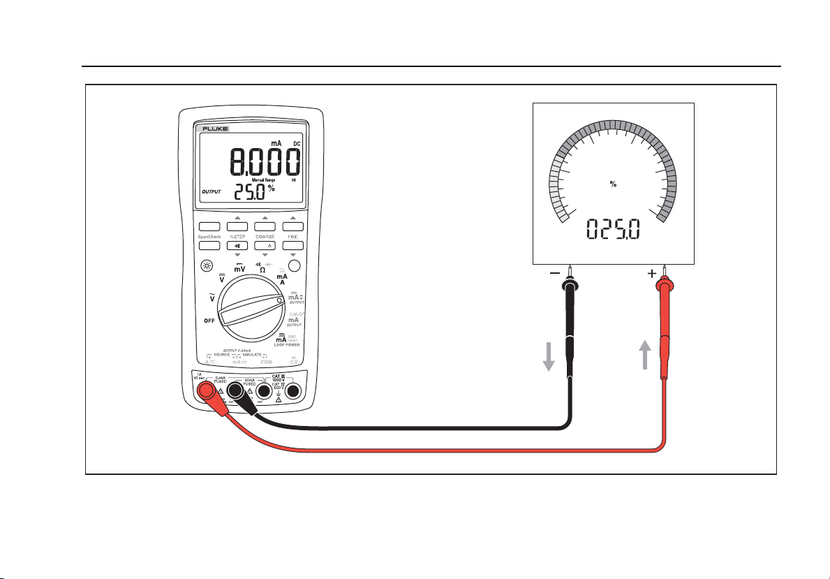
Source Mode
Source mode is selected automatically by inserting the
test leads into the SOURCE + and − jacks as shown in
Figure 1. The arrows show the conventional current flow.
Use source mode whenever it is necessary to supply
current into a passive circuit such as a current loop with
no loop supply. Source mode depletes the battery faster
than simulate mode, so use simulate mode whenever
possible.
The display looks the same in source and simulate
modes. The way to tell which mode is in use is to see
which pair of output jacks is in use.
ProcessMeter™
Using the Current Output Functions
21
0%
RANGEHOLD
REL
MIN MAX
Hz
100%
789
PROCESSMETER
40
20
0100
80
60
anw010f.eps
Figure 1. Sourcing Current
789/787B
Users Manual
22
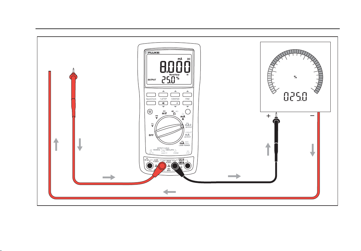
Simulate Mode
Simulate mode is so named because the meter simulates
a current loop transmitter. Use simulate mode when an
external dc voltage of 15 to 48 V is in series with the
current loop under test.
Caution
Set the rotary function switch to one of the
mA output settings BEFORE connecting the
test leads to a current loop. Otherwise, a low
impedance from the other rotary function
switch positions could be presented to the
loop, causing up to 35 mA to flow in the loop.
Simulate mode is selected automatically by inserting the
test leads into the SIMULATE + and − jacks as shown in
Figure 2. The arrows show the conventional current flow.
Simulate mode conserves battery life, so use it instead of
source mode whenever possible.
The display looks the same in source and simulate
modes. The way to tell which mode is in use is to see
which pair of output jacks is in use.
Changing the Current Span
The meter’s current output span has two settings (with
overrange to 24 mA):
•4 mA = 0 %, 20 mA = 100 % (factory default)
•0 mA = 0 %, 20 mA = 100 %
To find out which span is selected, turn the rotary function
switch to OUTPUT mA [, short the OUTPUT SOURCE +
and − jacks, and observe the 0 % output level.
To toggle and save the current output span in nonvolatile
memory (retained when the power is turned off):
1. Turn off the meter.
2. Hold down R while turning the meter on.
3. Wait at least 2 seconds until the new range shows as
0-20 or 4-20 and then release R.
ProcessMeter™
Using the Current Output Functions
23
0%
RANGEHOLD
REL
MIN MAX
Hz
100%
789
PROCESSMETER
dc V
Power Supply
40
20
0100
80
60
COM +24V
anw011f.eps
Figure 2. Simulating a Transmitter
789/787B
Users Manual
24
Producing a Steady mA Output
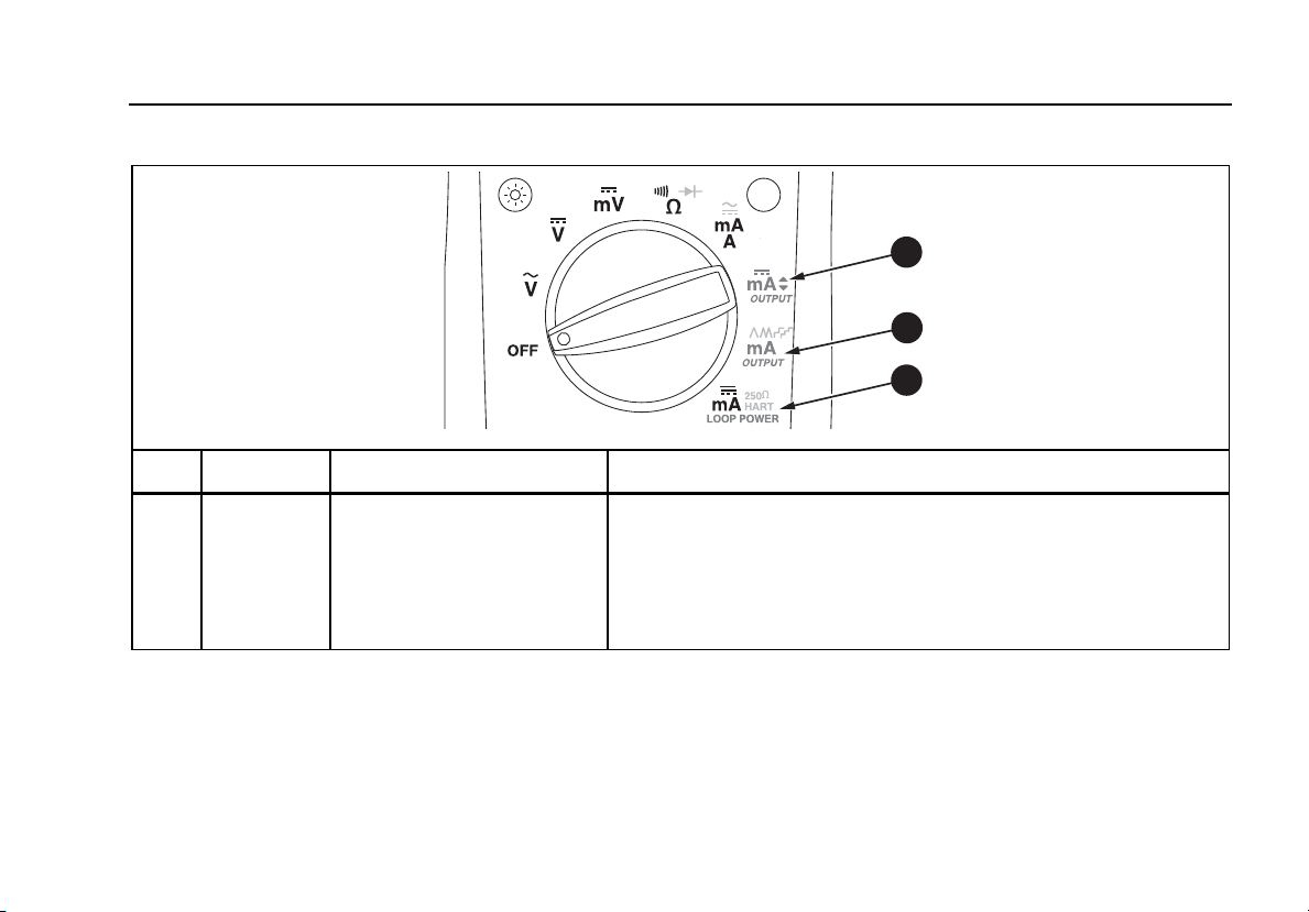
When the rotary function switch is in the OUTPUT mA [
position, and the OUTPUT jacks are connected to an
appropriate load, the meter produces a steady mA dc
output. The meter begins sourcing or simulating 0 %. Use
the pushbuttons to adjust the current as shown in Table 8.
Select either sourcing or simulating by choosing the
SOURCE or SIMULATE output jacks.
If the meter cannot deliver the programmed current
because the load resistance is too high or the loop supply
voltage is too low, dashes (-----) appear on the numeric
display. When the impedance between the SOURCE
jacks is low enough, the meter will resume sourcing.
Note
The STEP pushbuttons described Table 9 are
available when the meter is producing a steady
mA output. The STEP pushbuttons go to the
next multiple of 25 %.
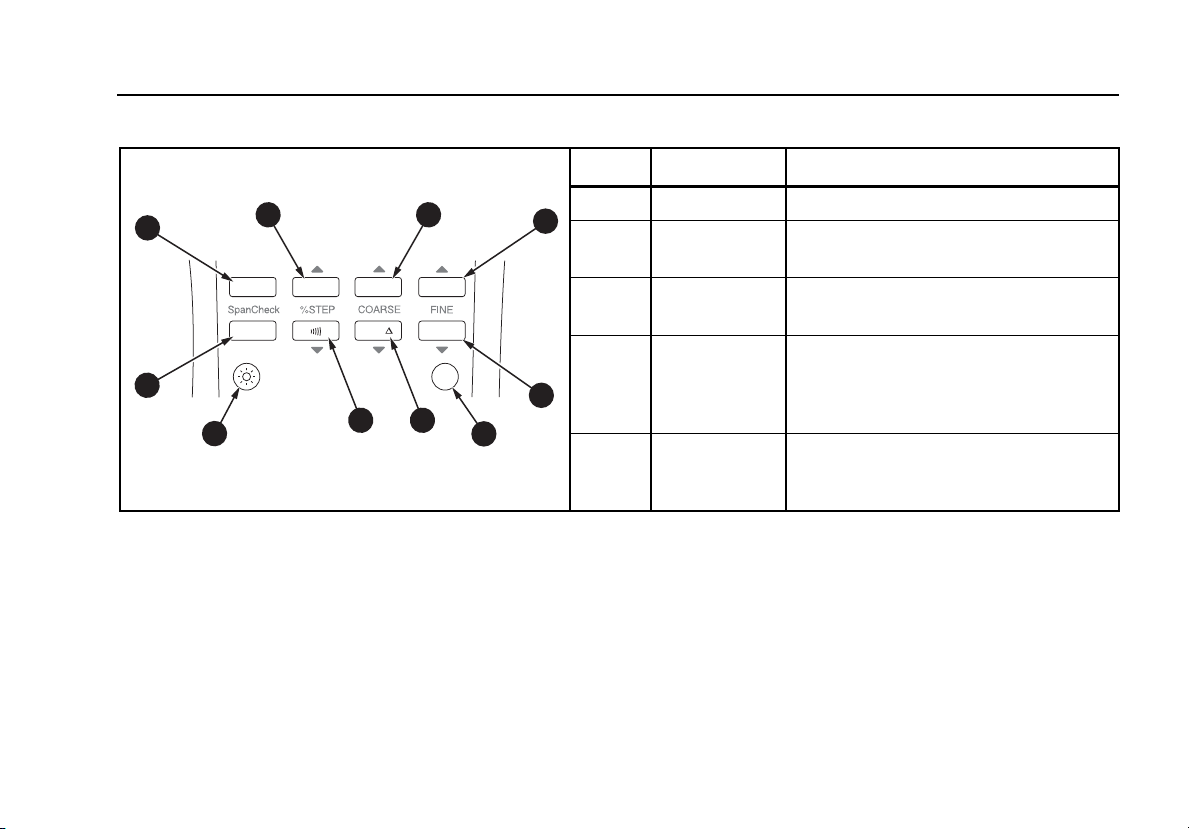
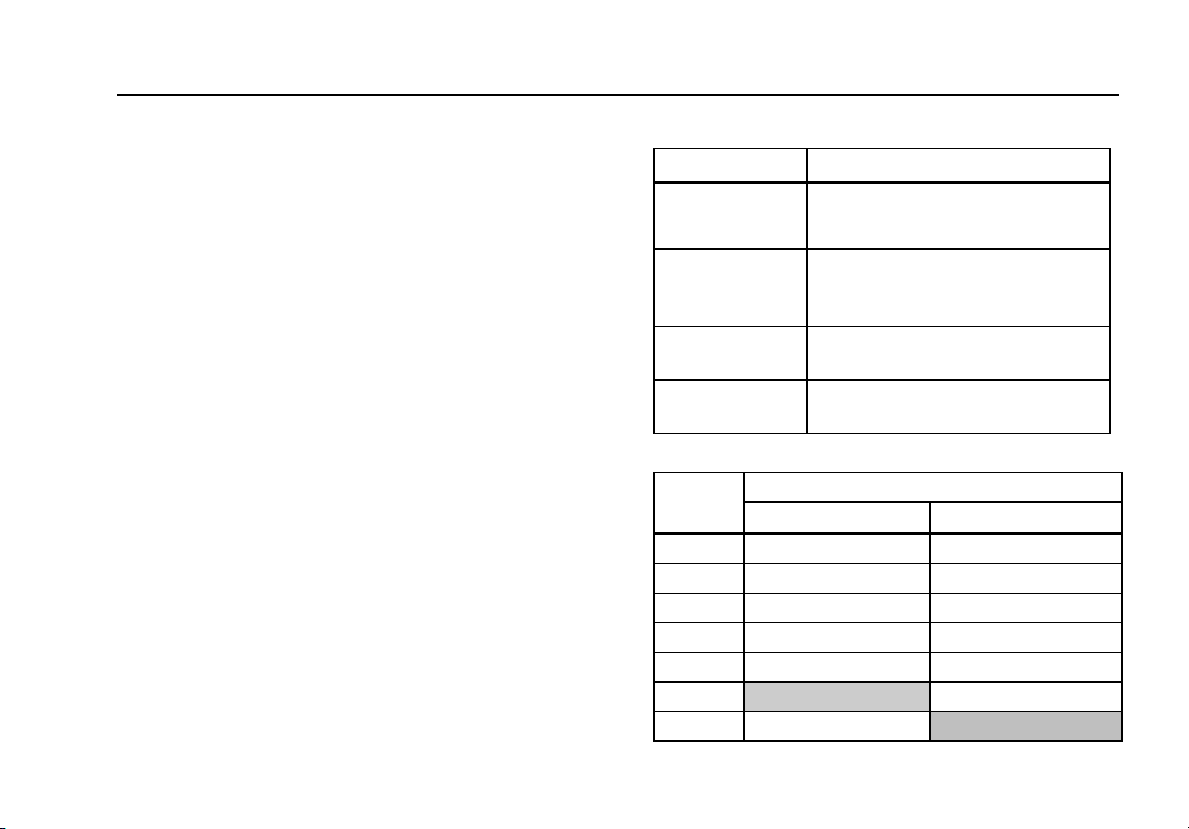
Table 8. mA Output Adjust Pushbuttons
Pushbutton Adjustment
X
R
COARSE
Adjusts up 0.1 mA
X
M
FINE
Adjusts up 0.001 mA
FINE
h
W
Adjusts down 0.001 mA
COARSE
r
W
Adjusts down 0.1 mA
ProcessMeter™
Using the Current Output Functions
25
Manually Stepping the mA Output
When the rotary function switch is in the OUTPUT mA [
position, and the OUTPUT jacks are connected to an
appropriate load, the meter produces a steady mA dc
output. The meter begins sourcing or simulating 0 %. Use
the pushbuttons to step the current up and down in 25 %
increments as shown in Table 9. See Table 10 for mA
values at each 25 % step.
Select either sourcing or simulating by choosing the
SOURCE or SIMULATE output jacks.
If the meter cannot deliver the programmed current
because the load resistance is too high or the loop supply
voltage is too low, dashes (-----) appear on the numeric
display. When the impedance between the SOURCE
jacks is low enough, the meter will resume sourcing.
Note
The COARSE and FINE adjustment pushbuttons
described in Table 8 are available when
manually stepping the mA output.
Table 9. mA Stepping Pushbuttons
Pushbutton Adjustment
X
M
% STEP
Adjusts up to the next higher 25 %
step
% STEP
G
W
Adjusts down to the next lower
25 % step
Span Check Sets to 100 % value
Span Check
Sets to 0 % value
Table 10. mA Step Values
Value (for each span setting)
Step 4 to 20 mA 0 to 20 mA
0 % 4.000 mA 0.000 mA
25 % 8.000 mA 5.000 mA
50 % 12.000 mA 10.000 mA
75 % 16.000 mA 15.000 mA
100 % 20.000 mA 20.000 mA
120 % 24.000 mA
125 % 24.000 mA
789/787B
Users Manual
26
Auto Ramping the mA Output
Auto ramping gives the ability to continuously apply a
varying current stimulus from the meter to a transmitter,
while hands remain free to test the response of the
transmitter. Select either sourcing or simulating by
choosing the SOURCE or SIMULATE jacks.
When the rotary function switch is in the OUTPUT
Ymonp position, and the output jacks are
connected to an appropriate load, the meter produces a
continuously repeating 0 % - 100 % - 0 % ramp in a
choice of four ramp waveforms:
m0 % - 100 % - 0 % 40-second smooth ramp
(default)
o0 % - 100 % - 0 % 15-second smooth ramp
n0 % - 100 % - 0 % Stair-step ramp in 25 % steps,
pausing 15 seconds at each step. Steps listed in
Table 10.
p0 % - 100 % - 0 % Stair-step ramp in 25 % steps,
pausing 5 seconds at each step. Steps are listed in
Table 10.
The ramp times are not adjustable. Press J (Blue) to
cycle through the four waveforms.
Note
At any time during auto ramping, the ramp can
be frozen simply by moving the rotary function
switch to the mA [position. Then the COARSE,
FINE, and % STEP adjust pushbuttons can be
used to make adjustments.
Power-Up Options
To select a power-up option:
1. Push and hold the pushbutton shown in Table 11.
2. Turn the rotary function switch from OFF to the
position listed in Table 11.
3. Wait 2 seconds before you release the pushbutton
after powering up the Meter.
The setting for current span, backlight, and beeper is
retained when the power is turned off. You must repeat
the other options for each operating session.
ProcessMeter™
Power-Up Options
27
Table 11. Power-Up Options
Option Button
Switch
Position Default Display Action Taken
Current Span R All Retains setting - or - Toggles between 0-20 mA and
4-20 mA range
Backlight Timeout K All Retains setting /Enables/Disables the auto-off
on backlight after 2 minutes
Beeper G All Retains setting / Enables/Disables beeper
Auto Power-Off
Note: Auto power-off is
always disabled when
MIN MAX recording is on.
J
(Blue) All Enabled
Disables the feature that turns
off the power after 30 minutes
of inactivity.
LCD segments H
VAC, mA,
Source,
Ramp,
Loop
Disabled All segments
Display HOLD (as long as
button pushed)
Firmware version H VDC Disabled ex: Display firmware version (as
long as button is pushed)
Model number H mVDC Disabled ex: Display model number (as long
as button is pushed)
Go to Calibration mode HΩ Disabled Calibration mode starts
789/787B
Users Manual
28
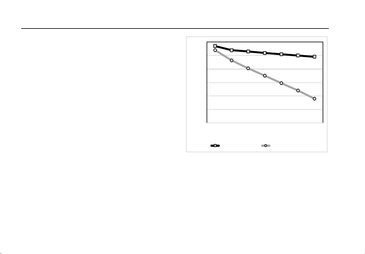
Loop Power Supply Mode (789 only)
The Loop Power Supply Mode can be used for powering
up a process instrument (transmitter). While in Loop
Power Mode, the meter acts like a battery. The process
instrument regulates the current. At the same time, the
meter measures the current that the process instrument is
drawing.
The meter supplies loop power at a nominal 24 V dc. An
internal series resistance of 250 Ω can be switched in for
communication with HART and other smart devices by
pressing J (Blue). See Figure 3. Pressing J (Blue)
again switches out this internal resistance.
When loop power is enabled, the meter is configured to
measure mA and >24 V dc is sourced between the mA
and A jacks. The mA jack is the common and the A jack is
at >24 V dc. Connect the meter in series with the
instrument current loop. See Figure 4.
20
22
24
26
28
30
32
04812162024
Voltage (V)
Current (mA)
Loop Voltage w/o 250 ΩLoop Voltage w/ 250 Ω
anw020f.eps
Figure 3. Loop Power Voltage vs. Current
ProcessMeter™
Loop Power Supply Mode (789 only)
29
0%
RANGEHOLD
REL
MIN MAX
Hz
100%
789
PROCESSMETER
TEST DC PWR
+–+–
–+
anw009f.eps
Figure 4. Connections for Supplying Loop Power
789/787B
Users Manual
30
Battery Life
Warning
To avoid false readings, which could lead to
possible electric shock or personal injury,
replace the battery as soon as the battery
indicator (b) appears.
Table 12 shows typical alkaline battery life. To preserve
battery life:
•Use current simulation instead of sourcing when
possible.
•Avoid using the backlight.
•Do not disable the automatic power-off feature.
•Turn the meter off when not in use.
Table 12. Typical Alkaline Battery Life
Meter Operation Hours
Measuring any parameter 140
Simulating Current 140
Sourcing 12 mA into 500 Ω 10
Maintenance
This section provides some basic maintenance
procedures. Repair, calibration, and servicing not covered
in this manual must be performed by qualified personnel.
For maintenance procedures not described in this manual,
contact a Fluke Service Center.
Periodically wipe the case with a damp cloth and
detergent; do not use abrasives or solvents.
Warning
To prevent possible electrical shock, fire, or
personal injury:
•Do not put battery cells and battery packs
near heat or fire. Do not put in sunlight.
•Replace a blown fuse with exact replacement
only for continued protection against arc
flash.
•Do not operate the Product with covers
removed or the case open. Hazardous voltage
exposure is possible.
•Use only specified replacement parts.
•Use only specified replacement fuses.
•Have an approved technician repair the
Product.
ProcessMeter™
Maintenance
31
Calibration
Calibrate the meter once a year to ensure that it performs
according to its specifications. Contact a Fluke Service
Center for instructions.
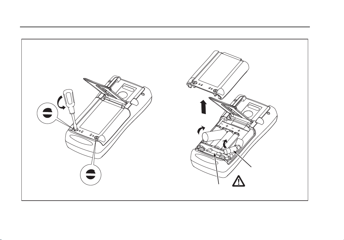
Replacing the Batteries
Warning
For safe operation and maintenance, repair
the Product before use if the battery leaks.
To replace the batteries:
1. Remove the test leads and turn the Meter OFF. See
Figure 5.
2. With a standard blade hand screwdriver, turn each
battery door screw counterclockwise so that the slot is
parallel with the screw picture molded into the case.
3. Lift off the battery door.
4. Remove the meter's batteries.
5. Replace with four new AA alkaline batteries.
6. Reinstall the battery door and tighten screws.
789/787B
Users Manual
32
F1
F2
anw037.eps
Figure 5. Replacing the Batteries and Fuses
ProcessMeter™
Maintenance
33
Replacing a Fuse
! Warning
To avoid personal injury or damage to the
meter, use only the specified replacement
fuse, 440 mA 1000 V fast-blow, Fluke PN
943121.
Both current input jacks are fused with separate 440 mA
fuses. To determine if a fuse is blown:
1. Turn the rotary function switch to W.
2. Plug the black test lead into COM, and the red test
lead into the A c input.
3. Using an ohmmeter, check the resistance between
the meter test leads. If the resistance is about 1 Ω,
the fuse is good. An open reading means that fuse
F2 is blown.
4. Move red test lead to .
5. Using an ohmmeter, check the resistance between
the meter test leads. If the resistance is about 14 Ω,
the fuse is good. An open means that fuse F1 is
blown.
If a fuse is blown, replace it as follows. Refer to Figure 6
as necessary:
1. Remove the test leads from the meter and turn the
meter OFF.
2. With a standard blade hand screwdriver, turn each
battery door screw counterclockwise so that the slot
is parallel with the screw picture molded into the
case.
3. Remove either fuse by gently prying one end loose,
then sliding the fuse out of its bracket.
4. Replace the blown fuse(s).
5. Replace the battery access door. Secure the door by
turning the screws one-quarter turn clockwise.
789/787B
Users Manual
34
If the Meter does not Work
•Examine the case for physical damage. If there is
damage, make no further attempt to use the meter,
and contact a Fluke Service Center.
•Check the battery, fuses, and test leads.
•Review this manual to make sure you are using the
correct jacks and rotary function switch position.
If the meter still does not work, contact a Fluke Service
Center. If the meter is under warranty, it will be repaired
or replaced (at Fluke’s option) and returned at no charge.
See the Warranty on the back of the title page for terms. If
the warranty has lapsed, the meter will be repaired and
returned for a fixed fee. Contact a Fluke Service Center
for information and price.
Replacement Parts and Accessories
! Warning
To avoid personal injury or damage to the
meter, use only the specified replacement
fuse, 440 mA 1000 V fast-blow, Fluke
PN 943121.
Note
When servicing the meter, use only the
replacement parts specified here.
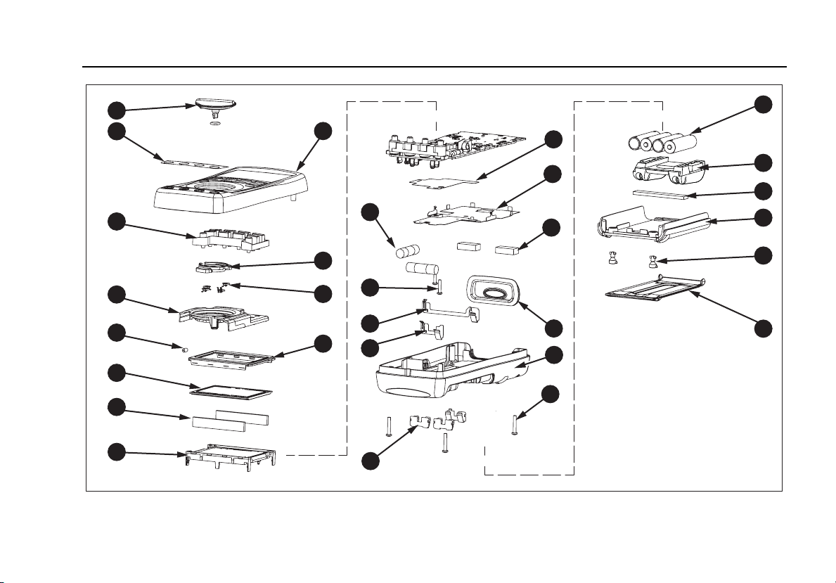
Replacement parts and some accessories are shown in
Figure 6 and listed in Table 13. Many more DMM
accessories are available from Fluke. For a catalog,
contact the nearest Fluke distributor.
To find out how to order parts or accessories use the
telephone numbers or addresses in How to Contact
Fluke.
ProcessMeter™
Replacement Parts and Accessories
35
2x
2x
3x
2x
2x
4x
1
29
24
28
25
26
27
29
20
19
21
17
23
3
10
11
12
14
15
16
2x
13
4
5
6
8
7
4x
18
22
W
anw038.eps
Figure 6. Replacement Parts
789/787B
Users Manual
36
Table 13. Replacement Parts
Item
Number Description Fluke PN
for 789 Fluke PN
for 787B Quantity
Knob Assembly with o-ring 658440 4772670 1
Decal, Top Case 1623923 4772201 1
Keypad 1622951 1
Top Shield 4772681 1
Top Shield Contact 674853 1
LCD Display 1883431 1
LCD Connectors, Elastomeric 1641965 2
Backlight/Bracket 4756199 1
Top Case with Lens Protector 1622855 4772197 1
Contact Housing 1622913 1
RSOB Contact 1567683 4
Mask 1622881 4772655 1
Fuse, 440 mA, 1000 V fast-blow 943121 2
PCB Screw 832220 2
Battery Contact, Negative 658382 1
Battery Contact, Positive 666438 1
Battery Contacts Dual 666435 3
ProcessMeter™
Replacement Parts and Accessories
37
Table 13. Replacement Parts (cont.)
Item
Number Description Fluke PN
for 789 Fluke PN
for 787B Quantity
Bottom Insulator 4811256 1
Bottom Shield 1675171 1
Shock Absorber 878983 1
IR Lens 658697 1
Bottom Case 659042 4772662 1
Case Screws 1558745 4
Battery, 1.5 V, 0-15 mA, AA Alkaline 376756 4
Accessory Mount with Probe Holders 658424 1
Shock Absorber 674850 1
Access Door, Battery/Fuse 1622870 1
Fasteners, Battery/Fuse Access Door 948609 2
Tilt-Stand 659026 1
- Test Leads variable[1]1 (set of 2)
- Alligator Clips variable[1]1 (set of 2)
[1] See www.fluke.com for more information about the test leads and alligator clips available for your region.
789/787B
Users Manual
38
Specifications
All specifications apply from +18 °C to +28 °C unless
stated otherwise.
All specifications assume a 5-minute warm-up period.
The standard specification interval is 1 year.
Note
“Counts” refers to the number of increments or
decrements of the least significant digit.
DC Volts Measurement
Range (V dc) Resolution Accuracy, ±(% of Reading + Counts)
4.000 0.001 V 0.1 % + 1
40.00 0.01 V 0.1 % + 1
400.0 0.1 V 0.1 % + 1
1000 1 V 0.1 % + 1
Input impedance: 10 M
Ω
(nominal), < 100 pF
Normal mode rejection ratio: > 60 dB at 50 Hz or 60 Hz
Common mode rejection ratio: > 120 dB at dc, 50 Hz, or 60 Hz
Overvoltage protection: 1000 V
ProcessMeter™
Specifications
39
DC Millivolts Measurement
Range (mV dc) Resolution Accuracy, ±(% of Reading + Counts)
400.0 0.1 mV 0.1 % + 2
AC Volts Measurement
Range (ac) Resolution Accuracy, ±(% of Reading + Counts)
50 Hz to 60 Hz 45 Hz to 200 Hz 200 Hz to 500 Hz
400.0 mV 0.1 mV 0.7 % + 4 1.2 % + 4 7.0 % + 4
4.000 V 0.001 V 0.7 % + 2 1.2 % + 4 7.0 % + 4
40.00 V 0.01 V 0.7 % + 2 1.2 % + 4 7.0 % + 4
400.0 V 0.1 V 0.7 % + 2 1.2 % + 4 7.0 % + 4
1000 V 1 V 0.7 % + 2 1.2 % + 4 7.0 % + 4
Specifications are valid from 5 % to 100 % of amplitude range.
AC conversion: true rms
Maximum crest factor: 3 (between 50 and 60 Hz)
For non-sinusoidal waveforms, add
±
(2 % reading + 2 % f.s.) typical
Input impedance: 10 M
Ω
(nominal), < 100 pF, ac-coupled
Common mode rejection ratio: > 60 dB at dc, 50 Hz, or 60 Hz
789/787B
Users Manual
40
AC Current Measurement
Range
45 Hz to 2 kHz Resolution Accuracy, ±(% of Reading + Counts) Typical Burden
Voltage
1.000 A (Note) 0.001 A 1 % + 2 1.5 V/A
Note: 440 mA continuous, 1 A 30 seconds maximum
Specifications are valid from 5 % to 100 % of amplitude range.
AC conversion: true rms
Maximum crest factor: 3 (between 50 and 60 Hz)
For non-sinusoidal waveforms, add
±
( 2 % reading + 2 % f.s.) typical
Overload protection 440 mA, 1000 V fast-blow fuse
DC Current Measurement
Range Resolution Accuracy, ±(% of Reading + Counts) Typical Burden
Voltage
30.000 mA 0.001 mA 0.05 % + 2 14 mV/mA
1.000 A (Note) 0.001 A 0.2 % + 2 1.5 V/A
Note: 440 mA continuous, 1 A 30 seconds maximum
Overload protection: 440 mA, 1000 V fast-blow fuse
ProcessMeter™
Specifications
41
Ohms Measurement
Range Resolution Measurement Current Accuracy, ±(% of Reading + Counts)
400.0 Ω 0.1 Ω 310 μA 0.2 % + 2
4.000 kΩ 0.001 kΩ 31 μA 0.2 % + 1
40.00 kΩ 0.01 kΩ 2.5 μA 0.2 % + 1
400.0 kΩ 0.1 kΩ250 nA 0.2 % + 1
4.000 MΩ 0.001 MΩ250 nA 0.35 % + 3
40.00 MΩ 0.01 MΩ125 nA 2.5 % + 3
Overload protection: 1000 V
Open circuit voltage: <3.9 V
789/787B
Users Manual
42
Frequency Counter Accuracy
Range Resolution Accuracy, ±(% of Reading + Counts)
199.99 Hz 0.01 Hz 0.005 % + 1
1999.9 Hz 0.1 Hz 0.005 % + 1
19.999 kHz 0.001 kHz 0.005 % + 1
Display updates 3 times/second at > 10 Hz
Frequency Counter Sensitivity
Input Range
Minimum Sensitivity (rms Sinewave)
5 Hz to 5 kHz*
AC DC
(approximate trigger level 5 % of full scale)
400 mV 150 mV (50 Hz to 5 kHz) 150 mV
4 V 1 V 1 V
40 V 4 V 4 V
400 V 40 V 40 V
1000 V 400 V 400 V
*Usable 0.5 Hz to 20 kHz with reduced sensitivity.
106 VHz max
ProcessMeter™
Specifications
43
Diode Test and Continuity Test
Diode test indication ........................................... Displays voltage drop across device, 2.0 V full scale. Nominal test current 0.3 mA at
0.6 V. Accuracy ±(2 % + 1 count).
Continuity test indication ..................................... Continuous audible tone for test resistance <100 Ω
Open circuit voltage ............................................. 2.9 V
Short circuit current ............................................. 310 μA typical
Overload protection ............................................. 1000 V rms
Loop Power Supply Voltage ................................. 24 V, Short Circuit protected
DC Current Output
Source mode
Span .............................................................. 0 mA or 4 mA to 20 mA, with overrange to 24 mA
Accuracy........................................................ 0.05 % of span
Compliance voltage ....................................... 28 V with battery voltage >~4.5 V
Simulate Mode
Span .............................................................. 0 mA or 4 mA to 20 mA, with overrange to 24 mA
Accuracy........................................................ 0.05 % of span
Loop voltage .................................................. 24 V nominal, 48 V maximum, 15 V minimum
Compliance voltage ....................................... 21 V for 24 V supply
Burden voltage .............................................. <3 V
789/787B
Users Manual
44
General Specifications
Maximum Voltage between
any Terminal and Earth Ground ........................... 1000 V
Fuse Protection for
mA inputs ............................................................... 0.44 A, 1000 V, IR 10 kA
Power
Battery Type ........................................................ IEC LR6 (AA Alkaline)
Operating ............................................................ -20 °C to +55 °C
Storage ................................................................ -40 °C to +60 °C
Altitude
Operating ............................................................ ≤2000 m
Storage ................................................................ ≤12 000 m
Frequency Overload Protection ........................... 106 V Hz max
Temperature coefficient
Measurements .................................................... 0.05 x specified accuracy per °C for temperatures <18 °C or >28 °C
Source ................................................................. 0.1 x specified accuracy per °C for temperatures <18 °C or >28 °C
Relative humidity ................................................... 95 % up to 30 °C, 75 % up to 40 °C, 45 % up to 50 °C, and 35 % up to 55 °C
Size ......................................................................... 10.0 cm X 20.3 cm X 5.0 cm (3.94 in X 8.00 in X 1.97 in)
Weight .................................................................... 610 g (1.6 lb)
Safety
General ............................................................... IEC 61010-1: Pollution Degree 2
Measurement ...................................................... IEC 61010-2-033: CAT IV 600 V / CAT III 1000 V
ProcessMeter™
Specifications
45
Electromagnetic Compatibility (EMC) ................. Accuracy for all ProcessMeter functions is not specified in RF field >3 V/m
International ......................................................... IEC 61326-1: Portable Electromagnetic Environment; IEC 61326-2-2
CISPR 11: Group 1, Class A
Group 1: Equipment has intentionally generated and/or uses conductively-coupled
radio frequency energy that is necessary for the internal function of the equipment itself.
Class A: Equipment is suitable for use in all establishments other than domestic and
those directly connected to a low-voltage power supply network that supplies buildings
used for domestic purposes. There may be potential difficulties in ensuring
electromagnetic compatibility in other environments due to conducted and radiated
disturbances.
Caution: This equipment is not intended for use in residential environments and may
not provide adequate protection to radio reception in such environments.
Emissions that exceed the levels required by CISPR 11 can occur when the equipment
is connected to a test object.
Korea (KCC) ........................................................ Class A Equipment (Industrial Broadcasting & Communication Equipment)
Class A: Equipment meets requirements for industrial electromagnetic wave equipment
and the seller or user should take notice of it. This equipment is intended for use in
business environments and not to be used in homes.
USA (FCC) .......................................................... 47 CFR 15 subpart B. This product is considered an exempt device per clause 15.103.
Gebruikershandleiding.com neemt misbruik van zijn services uitermate serieus. U kunt hieronder aangeven waarom deze vraag ongepast is. Wij controleren de vraag en zonodig wordt deze verwijderd.
Product:
Spelregels forum
Om tot zinvolle vragen te komen hanteren wij de volgende spelregels:
lees eerst de handleiding door;
controleer of uw vraag al eerder door iemand anders is gesteld;
probeer uw vraag zo duidelijk mogelijk te stellen;
heeft u een probleem en al geprobeerd om dit op te lossen, vermeld dit erbij aub;
heeft u een oplossing gekregen van een bezoeker dan horen wij dat graag in dit forum;
wilt u een reactie geven op een vraag of antwoord, gebruik dan niet dit formulier maar klik op de knop 'reageer op deze vraag';
uw vraag wordt direct op de website gezet; vermijd daarom persoonlijke gegevens in te vullen;
Belangrijk! Als er een antwoord wordt gegeven op uw vraag, dan is het voor de gever van het antwoord nuttig om te weten als u er wel (of niet) mee geholpen bent! Wij vragen u dus ook te reageren op een antwoord.
Belangrijk! Antwoorden worden ook per e-mail naar abonnees gestuurd. Laat uw emailadres achter op deze site, zodat u op de hoogte blijft. U krijgt dan ook andere vragen en antwoorden te zien.
Abonneren
Abonneer u voor het ontvangen van emails voor uw Fluke 787B bij:
nieuwe vragen en antwoorden
nieuwe handleidingen
U ontvangt een email met instructies om u voor één of beide opties in te schrijven.
Ontvang uw handleiding per email
Vul uw emailadres in en ontvang de handleiding van Fluke 787B in de taal/talen: Engels als bijlage per email.
De handleiding is 1,33 mb groot.
U ontvangt de handleiding per email binnen enkele minuten. Als u geen email heeft ontvangen, dan heeft u waarschijnlijk een verkeerd emailadres ingevuld of is uw mailbox te vol. Daarnaast kan het zijn dat uw internetprovider een maximum heeft aan de grootte per email. Omdat hier een handleiding wordt meegestuurd, kan het voorkomen dat de email groter is dan toegestaan bij uw provider.
Uw handleiding is per email verstuurd. Controleer uw email
Als u niet binnen een kwartier uw email met handleiding ontvangen heeft, kan het zijn dat u een verkeerd emailadres heeft ingevuld of dat uw emailprovider een maximum grootte per email heeft ingesteld die kleiner is dan de grootte van de handleiding.
Er is een email naar u verstuurd om uw inschrijving definitief te maken.
Controleer uw email en volg de aanwijzingen op om uw inschrijving definitief te maken
U heeft geen emailadres opgegeven
Als u de handleiding per email wilt ontvangen, vul dan een geldig emailadres in.
Uw vraag is op deze pagina toegevoegd
Wilt u een email ontvangen bij een antwoord en/of nieuwe vragen? Vul dan hier uw emailadres in.