Ferm 45
can be placed. Switching the transmission on and off.
18 Intermediate change wheel
Direction of rotation transmission; adjusting the trans-
mission ratio
19 Chance wheel transmission.
Adjusting transmission ratio; by means of placing fil-
ling rings the wheel can be adjusted in axial
direction(fig.3)
Longitudinal motion support
20 Transmission/lead screw
fixation intermediate change wheel; by means of in-
stalling the filling rings he wheel is axial adjustable and
with the lowest shaft nut the wheel is adjustable side-
ways
21 Intermediate change wheel.
In front of the thread-cutting wheel, behind the starting
wheel
22 Drive gear wheels for start.
by using this clamping device for surfacing and thread-
cutting the lock nut can stay open and the support
does not slip away; spindle and nut are less charged
then.
23 Clamping bolt cross slide.
CHISELS
During turning a chip is cut out of the piece of work. For this,
chisels have to be sharpened in a special and sharp form.
This form depends on the chisel material and on the mate-
rial you want to cut. Watch the next table.
On the basis of fig. 13 the corners of this table can be taken
over on a little piece square high-speed steel for making or
re-sharpening your own chisel. In this example we are tal-
king about a straight, right roughing tool. The dotted lines
indicate the original form of the bar. The sum of the angles
1,2 and 3 is always 90°. Angle 1 is the cutting-edge side ra-
ke, angle 2 the wedge angle and angle three the clearance
angle. For keeping the friction as low as possible, two ex-
tra clearance angles have been sharpened: angle 4 and
angle 6. Besides, a slope angle 5 has been installed. The
arrow indicates the starting direction. The front face is cal-
led the minor cutting face. The main cutting face is the part
on which the arrow has been drawn. In this way all possible
chisels can sharpen themselves, by which you have to say
where the main cutting face has to be and what the turning
material has to be.
A perfectly sharpened chisel has to be placed in the tool
holder in the right way now. Fig.14 indicates a correct pla-
cing of a pointed chisel. Point 1 is the center line. The tip of
the chisel has to stand exactly that high. If not, you have to
use bearing plates(5). The chisel always has to be placed
against the block body(4) and cannot extend farther than 1
to 1.5 time the tool shank thickness(2).
It goes without saying that all clamping bolts (3) have to be
tightened strongly.
TURNING SPEED
If the chisel have been sharpened and put, the piece of
work has been clamped well, the speed of the main shaft
has to be adjusted with the V-belts, watch fig. 15 and 16. In
the subjoined table some machining speeds which hap-
pen many times are indicated for different sorts of chisels
and materials.
With this table you can chose yourself for any diameter the
right speed. The only thing you have to do is fill in the desi-
red speed in the following formule.
v = cutting speed in meters per minute
d = diameter of the piece of work in mm
n = number of revolutions in revolutions per minute
π = constant, nl. 3,14
Calculation example:
1. A round piece of silver steel of 100 mm has to be turned
with a HSS chisel. You can find in the table that silver
steel has to be turned with 32m/min, v=32
Divide 32.000 by 100 gives a number of revolutions of
320 revolutions per minute. We put belt 2 on the hind-
most discs of the intermediate and main shaft pulley.
2. A piece of copper of 10 mm is turned with a HM-chisel.
v=200 and through that “n” comes far above the maxi-
mum number of revolutions. The highest number of re-
volutions can be adjusted. Belt two is layed on the
hindmost disc of the motor and main shaft pulley.
8 Ferm
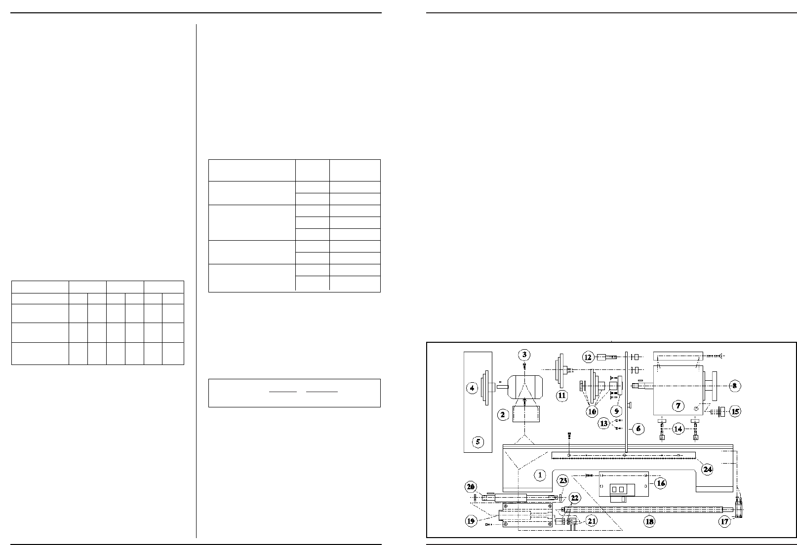
Annex 4
List of parts
BED/HEADSTOCK
Nr. Part
1. Bed
2. Motor base plate
3. Motor
4. Motor pulley
5. Guard
6. Mounting plate
7. Headstock with cover
8. Mains spindle
9. Bearing cover
10. Main spindle pulley
11. Idler
12. Tension pulley
13. Bolts with ring
14. Chuck headstock
15. Oil cup
16. Switch
17. Longitudinal and traerse
motion bearing
18. Longitudinal traverse (lathe
spindle
19. Bearing housing drive shaft
20. Drive shaft longitudinal and
transverse motion
21. Bush
22. Castle locking nuts
23. Axial thrust bearing
24. Gear rack
Anlage 4
Zubehörverzeichnis:
MASCHINENBETT/
SPINDELSTOCK
Nr. Zubehörteil
1. Maschinenbett
2. Motorstellplatte
3. Motor
4. Motorriemenscheibe
5. Schutzkasten
6. Befestigungsplatte
7. Spindelstock mit Deckel
8. Hauptwelle
9. Lagerdecke
10. Hauptwellenriemenscheibe
11. Zwischenriemenscheibe
12. Spannrolle
13. Bolzen mit Ring
14. Spannplatten Spindelstock
15. Ölstopfen
16. Schalter
17. Fördererlager
18. Längsvorschub (Leitspin-
del)
19. Lagergehäuse Antriebs-
welle
20. Antriebswelle Fördere
21. Kupplungsschale
22. Kronensicherungsmuttern
23. Axialdrucklager
24. Zahnstange
Bijlage 4
Onderdelenoverzicht
Bed/Vaste kop
Nr.
Onderdeel
1 bed
2 motorstelplaat
3 motor
4 motorpoelie
5 beschermingskast
6 bevestigingsplaat
7 vaste kop met deksel
8 hoofdas
9 lagerdeksel
10 hoofdaspoelie
11 tussenpoelie
12 spanrol
13 bouten met ring
14 spanplaten vaste kop
15 oliedop
16 schakelaar
17 transporteur-lager
18 langsvoeding (leispindel)
19 lagerhuis aandrijfas
20 aandrijfas transporteur
21 koppelbus
22 kroonborgmoeren
23 axiaal druklager
24 tandheugel
Pièce annexe 4
Aperçu pièces détachées:
Banc/Poupée fixe
N° pièce détachée
1. banc
2. plaquette de réglage mo-
teur
3. moteur
4. poulie de moteur
5. boîte de protection
6. plaquette de fixation
7. poupée fixe avec couvercle
8. essieu principa
9. couvercle de roulement
10. poulie de l'essieu principal
11. poulie intermédiaire
12. galet de tension
13. boulons avec rondelle
14. plaques de tension
poupées fixe
15. bouchon de vidange d'huile
16. commutateur
17. roulement de transport
18. avance longitudinale (bro-
che de guidage)
19. arbre d'entraînement de
boîte de roulement
20. arbre d'entraînement trans-
porteur
21. douille de connexion
22. écrous de blocage à cré-
neauxt
23. butée à vis sans fin
24. crémaillère
4