538649
26
Verklein
Vergroot
Pagina terug
1/50
Pagina verder
www.ferm.com 0701-22.1
GB Subject to change
D Änderungen vorbehalten
NL Wijzigingen voorbehouden
F Sous réserve de modifications
E Reservado el derecho de
modificaciones técnicas
P Reservado o direito a modificações
I Con riserva di modifiche
S Ändringar förbehålles
FIN Pidätämme oikeuden muutoksiin
N Rett till endringer forbeholdes
DK Ret til ændringer forbeholdes
Art. No. CRM1029
FCO-1524
www.ferm.com
GB
D
NL
F
E
P
I
S
FIN
N
DK
USERS MANUAL 05
GEBRAUCHSANWEISUNG 13
GEBRUIKSAANWIJZING 22
MODE D’EMPLOI 31
MANUAL DE INSTRUCCIONES 39
MANUAL DE INSTRUÇÕES 47
MANUALE UTILIZZATI 55
BRUKSANVISNING 63
KÄYTTÖOHJE 71
BRUKSANVISNING 79
BRUGERVEJLEDNING 87
02 Ferm Ferm 99
Exploded view
13
12
3
1
2
5
6
6
11
8
7
10
14
4
9
Fig. A
Ferm 0398 Ferm
Spare parts list
No. Description Position
400982 Air filter 3
400983 Gasket set 4, 6, 10
400984 Valve plate complete 5, 7 ,8
400985 Oil fill cap 15
400986 Carter cover with sealing 17, 22
400987 Oil lever 18, 19
806204 Bearing 6204 28
806202 Bearing 6202 31
400989 Fan 35
800035 Capacitor 41
400990 Non return valve 43
400991 Release pipe 44
400992 Pressing pipe 46
400993 Wheel mounting set 47, 48, 49, 51
400994 Wheel 50
400995 Rubber foot 52
400996 Nut for autoswitch 55
205915 Safty valve 58
400997 Pressure regulator 59
CRA1005 Pressure gauge 60
CRA1002 Autostop switch 62
Ferm 97
GB
D
NL
F
E
P
I
S
FIN
N
DK
04 Ferm
Ferm 05
COMPRESSOR OIL-BASED
The numbers in the following text correspond with the pitcures at page 2 - 3.
Carefully read this manual before using the machine. Make sure that you know how
the machine functions and how to operate it. Maintain the machine in accordance
with the instructions to make sure it functions properly. Keep this manual and the
enclosed documentation with the machine.
Contents
1. Machine details
2. Safety instructions
3. Use
4. Faults
5. Maintenance
1. MACHINE DETAILS
Technical specifications
The value of the noise level may rise from 1 to 10 dB(A) as a function of the environment in
which the compressor will be installed.
Product information
Fig. A
1 Cover
2. Handle
3. Switch
4. Automatic stop
5. Pressure regulator
6. Quick coupler (outlet)
7. Pressure gauge (pressure regulator)
8. Pressure gauge (tank)
9. Safety valve
10. Pressure pipe
Voltage 230 V~
Frequency 50 Hz
Capacity 1.5 hp (1100 W)
Idling speed 2850/min
IPClass IP 20
Tank contents 24litre
Air intake 160 l/min
Max. outlet pressure 8.0 Bar
Weight 24.0 kg
Sound power level 91.0 dB (A)
GB
D
NL
F
E
P
I
S
FIN
N
DK
96 Ferm
GB
D
NL
F
E
P
I
S
FIN
N
DK
Ferm 95
GB
D
NL
F
E
P
I
S
FIN
N
DK
06 Ferm
11. Air filter
12. Oil cap
13. Sump
14. Drain cock
2.SAFETYINSTRUCTIONS
Explanation of symbols
The following symbols are used in these instructions for use:
Read the instructions.
In accordance with essential applicable safety standards of European directives.
Denotes risk of personal injury, loss of life or damage to the tool in case of non-
observance of the instructions in this manual.
Risk of electric shock.
Remove the plug from the mains
Attention: the compressor could start automatically in case of a black-out and
subsequent reset
Caution: the compressor contains some parts wich might reach high temperatures
Wear ear protection.
Sound power level
Faulty and/or discarded electrical or electronic apparatus have to be collected at
the appropriate recycling locations.
Special safety instructions
Warning! The compressor may only be used in suitable rooms (with good ventilation and
an ambient temperature from +5°C to +40°C).
It is recommended to use the compressor with a maximum operation of 70% in one hour
under full load, to allow for proper operation of the product over time.
GB
D
NL
F
E
P
I
S
FIN
N
DK
Ferm 07
Check that the tank is fully decompressed before connections with the tank are
unscrewed.
It is prohibited to make holes in, or welds to, or purposely to distort the compressed air tank.
Do not perform any actions on the compressor without first having taken the plug out of the
plug socket.
Do not aim water jets or jets of flammable liquids at the compressor.
Do not place flammable objects near the compressor.
Switch the pressure regulator to the "0" position (OFF = uit) during dwell time.
Never aim the air jet at persons or animals (fig. 20).
Do not transport the compressor with the tank pressurised.
N.B.: some parts of the compressor such as the head and the feed-through pipes may
reach high temperatures. Do not touch these parts to avoid burns (fig. 12-13).
Transport the compressor by lifting it or by using the special grips or handles (fig. 5-6).
Children and animals should be kept far away from the area of operation of the machine.
If you use the compressor to spray paint:
a) Do not work in enclosed spaces or near naked flames.
b) Make sure that the environment in which you will be working has dedicated ventilation.
c) Protect your nose and mouth with a dedicated mask (fig. 21).
Do not use the compressor when the electrical cable or the plug is damaged, and instruct
an authorised Support Service to replace them with an original part.
When the compressor is placed on a surface higher than the floor, it should be secured to
prevent it from falling down during operation.
Do not put objects or your hands in the protective covers to avoid physical damage and
damage to the compressor.
Do not use the compressor as a blunt instrument against persons, objects or animals in
order to prevent serious damage.
If the compressor is no longer in use, always take the plug out of the plug socket.
Always make sure that compressed-air hoses are used for compressed air and which are
characterised by a maximum pressure adjusted to that of the compressor. Do not try to
repair the hose if it is damaged.
Electrical safety
Earthing regulations
This compressor has to be earthed while in use in order to protect the operator against electrical
shocks. The compressor is provided with a two-core cable plus an earth. The electrical
connection has to be made by a qualified technician. We recommend never disassembling the
compressor and neither making any other connections into the pressure regulator. Repairs
should be carried out by authorised Support Services or by other qualified centres.
Never forget that the earthing core is the green or the yellow/green wire. Never
connect this green wire to a terminal under load.
Before replacing the plug of the feed, make sure that the earth cable is connected. If in doubt,
please call in a qualified electrician and have the earthing checked.
GB
D
NL
F
E
P
I
S
FIN
N
DK
94 Ferm
CE
KONFORMITETSERKLÆRING (DK)
Vi erklærer at under almindeligt ansvar, at dette produkt er i overenstemmelse med følgende
normer eller normative dokumenter:
EN1012-1, EN60204-1, EN55014-1, ISO5388, EN55014-2, EN61000-3-2, EN61000-3-3
i overensstemmelse med direktiverne:
98/37/EC, 73/23/EEC, 89/336/EEC, 87/404/EEC, 2000/14/EC, 2002/95/EC, 2002/96/EC
Målt lydtrykniveau; Lwa = 91.1 dB(A)
Garanteret lydtrykniveau; Lwa = 91 dB(A)
2000/14/EC: Det garanterede lydtrykniveau er lavere end 96 dB(A). Procedure for
overholdelsesvurdering ifølge Anneks VI.
Bemyndiget organ: TUV product service GmbH
Bemyndiget organs identifikationsnummer: 70.403.06.078.13
fran 01-08-2006
ZWOLLE NL
J.A. Bakker - van Ingen J. Lodewijk
CEO Ferm BV Quality Manager Ferm Global
Det er vores hensigt til stadighed at forbedre vores produkter, og vi forbeholder os derfor til
enhver tid retten til at ændre produktspecifikationerne uden forudgående varsel.
Ferm BV • Lingenstraat 6 • 8028 PM Zwolle • Holland
GB
D
NL
F
E
P
I
S
FIN
N
DK
Ferm 93
Udskiftning/påfyldning af olie
Kompressoren er leveret med syntetisk olie "SAE 10W30". Det er anbefalet at udskifte alt
pumpesystemets olie inden for de første 100 driftstimer.
Skrue afløbsskruen (pakningen) af på beholderlåget, lad alt olien løbe ud og skrue skruen
på igen (fig. 17).
Fyld olie på via det øverste hul på beholderlåget (fig.18) indtil måleinstrumentets indikation
på pakningen (fig. 8) er nået.
Check pumpensystemets olieniveauet hver uge, og fyld om nødvendigt. Den syntetiske olie
har den fordel at den ikke mister dens karakteristisk, hverken om sommeren eller om vinteren.
Du bør ikke hælde brugt olie ud i afløbet eller naturen.
Overhold venligst nedenstående tabel, ved udskiftning af olie.
Olietype Driftstimer
Kvalitetsolie SAE 10W30 100 eller 6 måneder
Fejl
Skulle en fejl opstå, f.eks. pga. slidtage af en enhed, kontakt venligst serviceadressen på
garantibeviset. På bagsiden af denne manual finder du en tegning med alle dele, der kan
bestilles.
Miljø
For at undgå transportbeskadigelse leveres maskinen i en solid emballage. Emballagen er så
vidt muligt lavet af genbrugsmateriale. Genbrug derfor emballagen.
Defekte og/eller kasserede elektriske eller elektroniske maskiner skal afleveres på
en genbrugsplads.
Garanti
Garantibetingelser er beskrevet på det separat vedlagte garantibevis.
GB
D
NL
F
E
P
I
S
FIN
N
DK
08 Ferm
Extension cables
Long supply lines, extensions, cable reels and similar cause voltage dips and may prevent the
motor from starting. Sluggishness makes starting difficult at low temperatures under freezing
point (0°C). Only use an extension cable with a plug and earth, so never use damaged or
flattened extension cables. Check whether the extension cable is in a good condition. For this
device the extension cable should have a diameter of at least 2.5 mm
2
(this applies to a
maximum length of 20 metres). Always unroll extension cables fully before using them.
Electrical connection
Always check whether the input voltage of the motor corresponds to the mains voltage
indicated on the specification plate. The compressors are supplied with an electrical cable and
a two-pole plug + earth. It is important to connect the compressor with an earthed plug socket.
(fig. 9)
Never use the earth-wire instead of the neutral (0-wire). The earthing should take
place in accordance with accident prevention regulations (EN 60204).
3. USE
For homehold use only
NB: The information you will find in this manual has been written to assist the operator in the use
and maintenance of the compressor. Some illustrations in this manual show details which may
differ from those of your compressor.
Installation
After having taken the compressor out of its packaging (fig. 1) and having checked that it is in
perfect condition, and having noted that no damage occurred during transport, the following
acts should be performed. If not yet fitted, fit the rubber feet on the tank according to the
instructions represented in fig. 2. Place the compressor on a flat surface or at a maximum slope
of 10° (fig.3), in a well ventilated area, protected against atmospheric factors and not in
explosive surroundings. If the surface area is sloping and smooth, make sure that the
compressor will not move when in operation. If the surface area is a board or a shelf of a
bookcase, just make sure that they cannot fall down by securing them properly. For proper
ventilation and effective cooling, it is important that the compressor is positioned at least 100
cm from the wall (fig. 4).
Make sure that the compressor is transported in the right way, do not turn it upside
down and don't lift it with hooks or ropes (fig. 5-6).
Important! Before commissioning
The carter of this compressor is filled with oil at the factory. To avoid leaking oil during transport,
there is a liquid-proof sticker stuck on the oil cap.
GB
D
NL
F
E
P
I
S
FIN
N
DK
Ferm 09
Important! Remove the sticker before starting the compressor. The little gap in the oil cap is
necessary for a correct ventilation of the carter. The gauge at the bottom of the sump indicates
the oil level: this should now be level with the red dot (fig. 7 and 8).
Starting up
Check whether the mains voltage corresponds to that indicated on the electrical
specification plate (fig. 10), the permitted tolerance range should be within 5%.
Press the switch situated on the upper part into the "0" position according to the pressure
regulator type fitted on the device (fig. 11).
Put the plug in the plug socket (fig. 9) and start the compressor up by putting the switch of
the pressure regulator in the "I" position. The operation of the compressor is fully
automatic. The pressure regulator will stop the compressor when the maximum value has
been reached and start it up when the pressure drops below the minimum value. Normally
the difference in pressure is approx. 2 Bar/29 psi between the maximum and the minimum
value. For instance - The compressor will stop when it reaches 8 Bar (116 psi) (this is the
maximum operating pressure) and will start up automatically when the pressure within the
tank has dropped to 6 Bar (87 psi).
The head/cylinder/transmission pipe assembly may reach high temperatures, so
take care when working close to these parts and do not touch them to avoid burns
(fig. 12 - 13).
Adjusting the operating pressure
Fig. 14
It is not necessary continuously to use the maximum operating pressure, the compressed-air
tools often require less pressure. With regard to compressors supplied with a pressure
reduction valve it is necessary to set the operating pressure properly. It is possible to set the
operating pressure by using the turning knob on the reduction valve.
By turning clockwise, the pressure will be increased.
By turning anti-clockwise, the pressure will be reduced.
The compressor has two pressure gauges and two points to connect an air hose:
Pressure gauge on the left: pressure on left outlet. The pressure of left this outlet can be
regulated with help of the reduction valve.
Pressure gauge on the right: tank pressure + pressure on right outlet
The set pressure can be locked by turning the ring under the turning knob in the opposite
direction from the turning knob thereby fixing the turning knob. The set pressure is visible on the
manometer of the reduction valve.
4.FAULTS
Air loss
May be caused by a poor seal of a connection.
Check all connections by wetting them with soap and water.
GB
D
NL
F
E
P
I
S
FIN
N
DK
92 Ferm
Kompressoren vil ikke starte
Hvis kompressoren er svær at starte, check:
Om hovedspændingen stemmer overens med den på typepladen (fig. 10)
Om elektriske forlængerledninger anvendes med en kernefejl eller længdefejl.
Om arbejdsmiljøet for for koldt (under 0°C).
Om der er olie i beholderen for at garantere smørrelse (fig. 8)
Om der strømforsyning (stik korrekt forbundet, magneto termiske sikringer ikke er
ødelagte).
Kompressoren vil ikke slukke
Hvis kompressoren ikke slukkes når det maksimale tryk er opnået, vil sikkerhedventilern på
tanken aktiveres. Det er nødvenligt at kontakte den nærmeste autoriserede support
servicevirksomhed for reparation.
5. VEDLIGEHOLDELSE
Vedligeholdelse
Sørg for, at stikket til maskinen er taget ud af stikkontakten, når der skal udføres
vedligeholdelse på motoren.
Maskiner er blevet konstrueret, så de kan arbejde i længere perioder med et minimum af
vedligeholdelse. Korrekt vedligeholdelse og rengøring af maskinen er en forudsætning for lang
tids tilfredsstillende brug. Før enhver form for vedligeholdelse foretages, sørg altid for at:
Universalknappen er står "0" positionen.
Tryk regulatoren og kontakterne på strømfordelingstavlen er slukket i "0" positionen.
Lufttanken er helt uden tryk.
Rengøring
Kappen omkring motoren skal rengøres med en blød klud, helst hver gang maskinen har været
brugt. Ventilationsrillerne skal holdes fri for støv og snavs. Hvis snavset ikke vil gå af, bruges en
blød klud vredet op i sæbevand. Der må ikke bruges opløsningsmidler som f.eks. benzin, sprit,
salmiakspiritus o.l. Sådanne opløsningsmidler kan beskadige dele af plastic.
Smøring
Det er anbefalet at skille sugefiltret ad hver 50ende driftstime, og rengøre filterelementet ved at
puste det ved lufttryk (fig. 15). Det er anbefalet ar filterelement udskiftes mindst to gange hvert
år hvis kompressoren arbejder i et rent miljø; ofterer hvis arbejdsmiljøet er støvet.
Kompressoren udvikler kondensvand som samles i tanken. Det er nødvendigt at fjerne
kondensvand i tanken mindst én gang om ugen, ved at åbne aftapningshanen (fig. 16) under
tanken. Vær forsigtig når trykluft er i flasken, da vand kan komme ud under stort tryk. Anbefalet
tryk maks. 1-2 Bar.
Kondensvand fra den oliesmurte kompressor bør ikke hældes ud i afløbe,t eller
hældes ud i naturen, da det indeholder olie.
GB
D
NL
F
E
P
I
S
FIN
N
DK
Ferm 91
Start
Check om hovedspændingen stemmer overens med den som er indikeret på den
elektriske typeplade (fig. 10), den tilladte tolerance rækkevidde bør være inden for 5%.
Tryk på knappen placeret på øverste del ind til “0” position, efter typen på trykregulatoren
monteret på enheden (fig. 11).
Put stikket i stikkontakten (fig. 9), og start kompressoren ved at sætte knappen på
trykregulatoren i “I” position. Driften af kompressoren er totalt automatisk.
Trykregulatoren vil stoppe kompressoren når den maksimale værdi er opnået, og starte op
når trykket falder til under minimumværdien. Normalt er forskellen i tryk ca. 2 Bar/29 psi
mellem maksimum og minimum værdi. F.eks. - Kompressoren vil stoppe når den opnår 8
Bar (116 psi) (dette er det maksimale tryk ved drift), og vil automatisk starte op når trykket i
tanken er faldet til 6 Bar (87 psi).
Hovedet/cylinder/transmissionsrør kan opnå høje temperaturer, så hver forsigtig
når der arbejdes tæt på disse dele, og for at forebygge forbrændinger (fig. 12-13)
bør du ikke komme i kontakt med dem. «
Juster driftstrykket
Fig. 14
Det er ikke nødvendigt at anvende det maksimale driftstryk konstant, trykluftsværktøjet kræver
ofte mindre tryk. Ved kompressorer leveret med en trykreducerende ventil, er det nødvendigt
at indstille driftstrykket korrekt. Det er muligt at indstille driftstrykket ved at anvende
drejeknappen på reductionsventilen.
Ved at dreje denne med uret, vil trykket øges.
Ved at dreje denne mod uret, vil trykket mindskes.
Kompressoren har to trykmålere og to tilslutningspunkter for en trykluftslange:
Venstre trykmåler: tryk på venstre udtag. Trykket på venstre udtag kan reguleres med
reduktionsventilen.
Højre trykmåler: Tanktryk + tryk på højre udtag
Det indstillede tryk kan låses ved at dreje ringen under drejeknappen i den modsatte retning af
drejeknappen, herved fastlåses drejeknappen. Det indstillede tryk er synligt på trykmåleren på
reduktionsventilen.
4. FEJL
Lufttab
Kan være forårsaget af en dårlig tætning af en forbindelse.
Check alle forbindelser ved at væde dem med sæbe og vand.
Kompressoren køre men komprimere ikke
Fig. 19
Kan være forårsaget af ventilerne (C-C2) eller en pakning (B1-B2) som er ødelagt.
Udskift de ødelagte dele.
GB
D
NL
F
E
P
I
S
FIN
N
DK
10 Ferm
The compressor runs but does not compress
Fig. 19
May be caused by the valves (C-C2) or a gasket (B1-B2) being broken.
Replace the damaged part.
The compressor will not start
If the compressor is difficult to start, check:
whether the voltage of the mains corresponds to that on the specification plate (fig. 10)
whether electrical extension cables are being used with a faulty core or length.
whether the operating environment is too cold (below 0°C).
whether there is oil in the sump to guarantee lubrication (fig. 8)
whether there is electricity supply (plug properly connected, magneto-thermal fuses not
broken).
The compressor does not shut off
If the compressor does not shut off when the maximum pressure has been reached, the safety
valve of the tank will be activated. It is necessary to contact the nearest authorised Support
Service for the repair.
5.MAINTENANCE
Maintenance
Make sure that the plug is removed from the mains when carrying out maintenance
work on the motor.
The machines have been designed to operate over a long period of time with a minimum of
maintenance. Continuous satisfactory operation depends upon proper machine care and
regular cleaning. Before interfering in any way whatsoever with the compressor, please make
sure that:
The general line switch is in the "0" position.
The pressure regulator and the switches on the switch board are switched off in the "0"
position.
The air tank is fully decompressed.
Cleaning
Regularly clean the machine housing with a soft cloth, preferably after each use. Keep the
ventilation slots free from dust and dirt.
If the dirt does not come off use a soft cloth moistened with soapy water. Never use solvents
such as petrol, alcohol, ammonia water, etc. These solvents may damage the plastic parts.
Lubrication
It is recommended to disassemble the suction filter every 50 operating hours and to clean the
filter element by blowing it with compressed air (fig. 15). It is recommended that the filter
element is replaced at least once a year if the compressor is working in a clean environment;
GB
D
NL
F
E
P
I
S
FIN
N
DK
Ferm 75
Esimerkki: Kompressori pysähtyy, kun paine on 8 bar (116 psi) (enimmäiskäyttöpaine) ja
käynnistyy automaattisesti uudelleen, kun säiliön paine laskee arvoon 6 bar (87 psi).
Kannen/sylinterin/vaihteistoputken kokoonpano voi kuumentua, joten ole
varovainen näiden läheisyydessä äläkä kosketa niitä palovammojen välttämiseksi
(kuvat 12 - 13).
Käyttöpaineen säätäminen
Kuva 14
Suurinta käyttöpainetta tarvitaan vain harvojen työkalujen kanssa. Kompressoreissa, jotka
toimitetaan paineenalennusventtiilin kanssa on käyttöpaine säädettävä oikein. Käyttöpaine
voidaan säätää kiertämällä alennusventtiilin nuppia.
Paine kasvaa kiertämällä nuppia myötäpäivään.
Paine laskee kiertämällä nuppia vastapäivään.
Kompressorissa on kaksi painemittaria ja kaksi liitintä ilmaletkulle:
Vasemmanpuoleinen mittari: paine vasemmassa ulostulossa. Painetta tässä
vasemmassa ulostulossa voidaan säätää vähennysventtiilin avulla.
Oikeanpuoleinen mittari: säiliön paine + paine oikeassa ulostulossa
Asetettu paine voidaan lukita kiertämällä nupin alla olevaa rengasta vastakkaiseen suuntaan
nupin kanssa, jolloin nupin asento lukittuu. Asetettu paine näkyy alennusventtiilin
painemittarista.
4. VIAT
Vähäinen ilman tuotto
Voi johtua liitännän huonosta tiiveydestä.
Tarkista liitännät kastelemalla ne saippuavedellä.
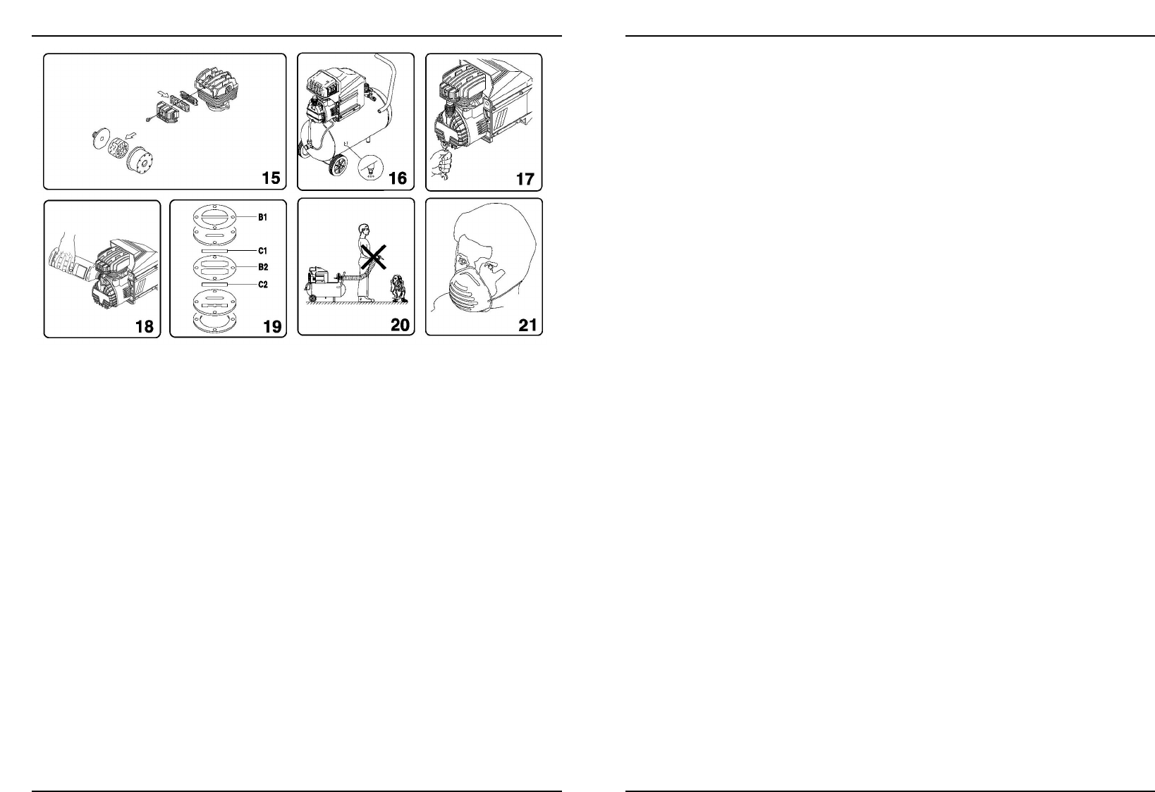
Kompressori on käynnissä, mutta ei tuota paineilmaa
Kuva 19
Syynä voivat olla venttiilit (C-C2) tai rikkoutunut tiiviste (B1-B2).
Vaihda viallinen osa uuteen.
Kompressori ei käynnisty
Tarkista seuraavat:
Vastaako verkkojännite tyyppikilvessä ilmoitettua jännitettä (kuva 10)
Onko mahdollisesti käytössä olevissa jatkojohdoissa vikaa tai niiden pituus liian suuri.
Onko toimintaympäristö liian kylmä (alle 0 °C).
Onko säiliössä öljyä voitelua varten (kuva 8)
Toimiiko virtasyöttö (pistoke kunnolla rasiassa, sulakkeet ehjät).
Kompressori ei pysähdy
Jos kompressori ei pysähdy, kun enimmäispaine saavutetaan, säiliön turvaventtiili aktivoituu.
Ota tällöin yhteys valtuutettuun huoltoon.
GB
D
NL
F
E
P
I
S
FIN
N
DK
26 Ferm
Installatie
Pak de compressor uit de verpakking (fig. 1) en controleer de compressor op transportschade.
Voer vervolgens de volgende handelingen uit. De rubber doppen op de tank monteren als ze
nog niet gemonteerd zijn, volgens de instructies weergegeven op fig.2.
De compressor op een vlak oppervlak zetten of ten hoogste met een helling van 10° (fig.3), in
een goed geventileerde plaats, beschermd tegen atmosferische factoren en niet in explosieve
omgevingen. Als het oppervlak helt en glad is, erop letten dat de compressor zich niet
verplaatst als hij werkt. Als het oppervlak een legplank is of een schap van een boekenkast,
zich ervan verzekeren dat ze niet kunnen vallen door ze op de juiste manier vast te zetten. Om
een goede ventilatie en een doeltreffende afkoeling te bekomen is het belangrijk dat de
compressor zich op minstens 100 cm van een muur (fig. 4) bevindt.
Erop letten dat de compressor op de juiste manier vervoerd wordt, hem niet
ondersteboven keren en niet opheffen met haken of touwen (fig.5-6).
Let op! Voor in gebruik name
Het carter van deze compressor is reeds in de fabriek met olie gevuld. Om lekkage tijdens het
transport te voorkomen, is een vloeistofdichte sticker op de oliedop geplakt.
Belangrijk! Verwijder de sticker voordat de compressor wordt gestart. Het gaatje in de oliedop
is nodig voor een goede ventilatie van het carter. Het peilglas onderaan het carter geeft het
olieniveau aan: dit behoort nu gelijk te staan aan de rode stip (fig. 7 en 8).
Opstarten
Controleren of de netspanning overeenstemt met die aangeduid op het plaatje elektrische
gegevens (fig. 10), het toegelaten tolerantieveld moet binnen de 5% liggen.
De schakelaar, aangebracht op het bovenste deel, drukken in de “0” stand volgens het
type van drukregelaar gemonteerd op het apparaat (fig.11).
De stekker in het stopcontact steken (fig. 9) en de compressor opstarten door de
schakelaar van de drukregelaar in stand “I” te brengen. De werking van de compressor is
volledig automatisch, geregeld door de drukregelaar die hem stilzet wanneer de druk in de
tank de maximum waarde bereikt en die hem terug doet starten als de druk naar het
minimum niveau zakt. Normalerwijze is het verschil in druk ongeveer 2 bar/29 psi tussen
de maximum en de minimum waarde.
Bv - De compressor stopt als hij 8 bar (116 psi) bereikt (max. werkdruk) en start
automatisch als de druk in de tank gedaald is tot 6 bar (87 psi).
Na de compressor aangesloten te hebben door de stekker in het stopcontact te steken, de
tank tot de maximum druk vol te pompen en daarbij de juiste werking van de compressor
nagaan.
De kop/cilinder/overbrengingsbuis groep kan hoge temperaturen bereiken,
opletten dat als men in de nabijheid van deze onderdelen werkt, en ze niet
aanraken om brandwonden te vermijden (fig. 12 - 13).
Regeling van de werkingsdruk
Fig.14
Het is niet nodig steeds de maximum werkingsdruk te gebruiken, meestal zelfs heeft het
pneumatische gereedschap minder druk nodig.
GB
D
NL
F
E
P
I
S
FIN
N
DK
26

Hulp nodig? Stel uw vraag in het forum

Spelregels

Misbruik melden

Gebruikershandleiding.com neemt misbruik van zijn services uitermate serieus. U kunt hieronder aangeven waarom deze vraag ongepast is. Wij controleren de vraag en zonodig wordt deze verwijderd.

Product:

Bijvoorbeeld antisemitische inhoud, racistische inhoud, of materiaal dat gewelddadige fysieke handelingen tot gevolg kan hebben.

Bijvoorbeeld een creditcardnummer, een persoonlijk identificatienummer, of een geheim adres. E-mailadressen en volledige namen worden niet als privégegevens beschouwd.

Spelregels forum

Om tot zinvolle vragen te komen hanteren wij de volgende spelregels:

Belangrijk! Als er een antwoord wordt gegeven op uw vraag, dan is het voor de gever van het antwoord nuttig om te weten als u er wel (of niet) mee geholpen bent! Wij vragen u dus ook te reageren op een antwoord.

Belangrijk! Antwoorden worden ook per e-mail naar abonnees gestuurd. Laat uw emailadres achter op deze site, zodat u op de hoogte blijft. U krijgt dan ook andere vragen en antwoorden te zien.

Abonneren

Abonneer u voor het ontvangen van emails voor uw Ferm CRM1029 FCO-1524 bij:


U ontvangt een email met instructies om u voor één of beide opties in te schrijven.


Ontvang uw handleiding per email

Vul uw emailadres in en ontvang de handleiding van Ferm CRM1029 FCO-1524 in de taal/talen: Nederlands, Duits, Engels, Frans, Italiaans, Portugees, Spaans, Deens, Zweeds, Noors, Fins als bijlage per email.

De handleiding is 6,76 mb groot.


U ontvangt de handleiding per email binnen enkele minuten. Als u geen email heeft ontvangen, dan heeft u waarschijnlijk een verkeerd emailadres ingevuld of is uw mailbox te vol. Daarnaast kan het zijn dat uw internetprovider een maximum heeft aan de grootte per email. Omdat hier een handleiding wordt meegestuurd, kan het voorkomen dat de email groter is dan toegestaan bij uw provider.

Stel vragen via chat aan uw handleiding

Stel uw vraag over deze PDF

Uw handleiding is per email verstuurd. Controleer uw email

Als u niet binnen een kwartier uw email met handleiding ontvangen heeft, kan het zijn dat u een verkeerd emailadres heeft ingevuld of dat uw emailprovider een maximum grootte per email heeft ingesteld die kleiner is dan de grootte van de handleiding.

Er is een email naar u verstuurd om uw inschrijving definitief te maken.

Controleer uw email en volg de aanwijzingen op om uw inschrijving definitief te maken

U heeft geen emailadres opgegeven

Als u de handleiding per email wilt ontvangen, vul dan een geldig emailadres in.

Uw vraag is op deze pagina toegevoegd

Wilt u een email ontvangen bij een antwoord en/of nieuwe vragen? Vul dan hier uw emailadres in.


Info