1. Introduction
1 Introduction
1.1 General information ...........................................................................................................................1
1.2 Markings in these operation instructions .......................................................................................... 1
2 Safety
2.1 General information ...........................................................................................................................3
2.2 Before the drive .................................................................................................................................5
2.3 Loading .............................................................................................................................................6
2.4 Handling Performance ......................................................................................................................8
2.5 After the drive ....................................................................................................................................9
3 Undercarriage and vehicle registration
3.1 General information .........................................................................................................................11
3.2 Safety coupling AKS 3004 ..............................................................................................................12
3.3 Locking brake facilitiesng und Radbremsen ...................................................................................13
3.4 Overrunning equipment and wheel brakes .....................................................................................13
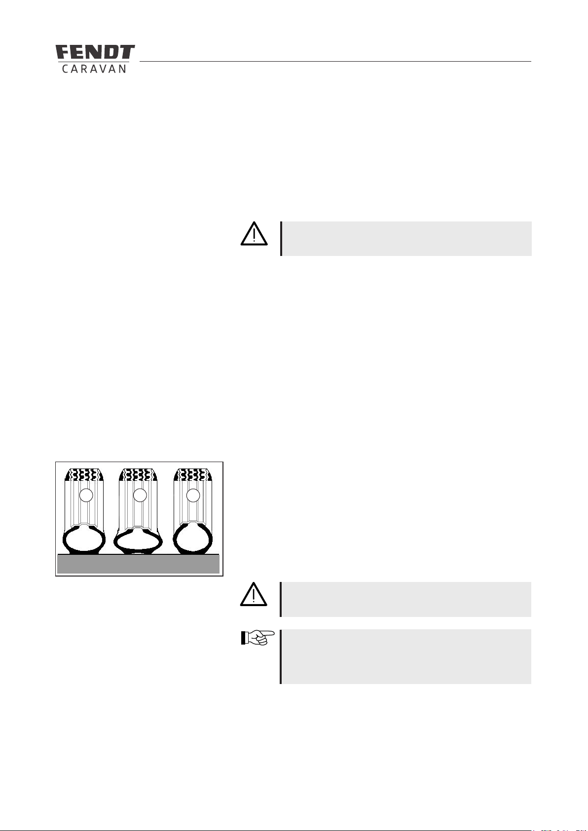
3.5 Rotating stanchions ........................................................................................................................15
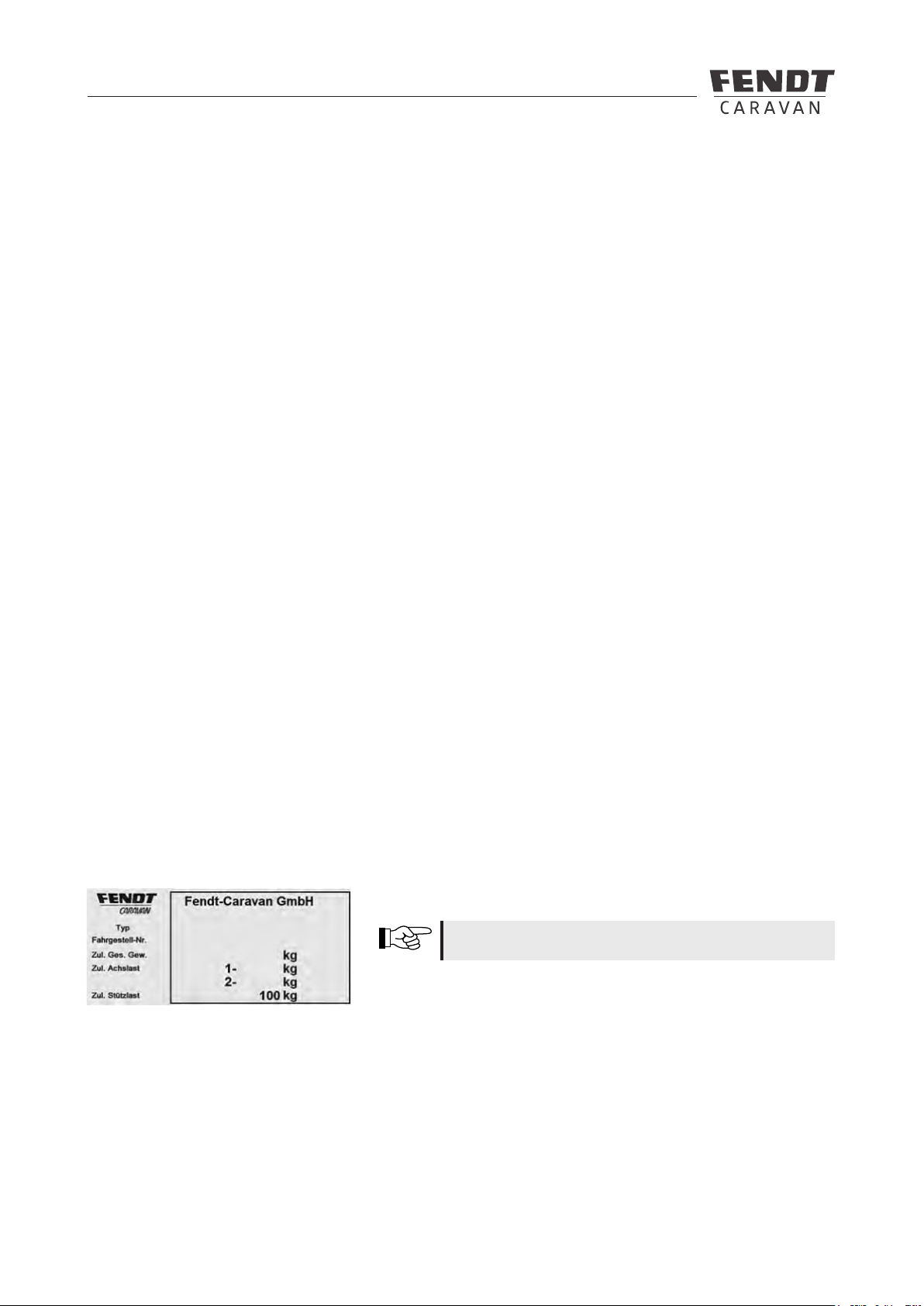
3.6 Vehicle registration .......................................................................................................................... 16
3.7 General inspection ..........................................................................................................................16
3.8 Fit for a Speed of 100 km/h ............................................................................................................16
3.9 Denition of mass ...........................................................................................................................17
4 Wheels, tires
4.1 Tires ................................................................................................................................................19
4.2 Tire pressure ...................................................................................................................................19
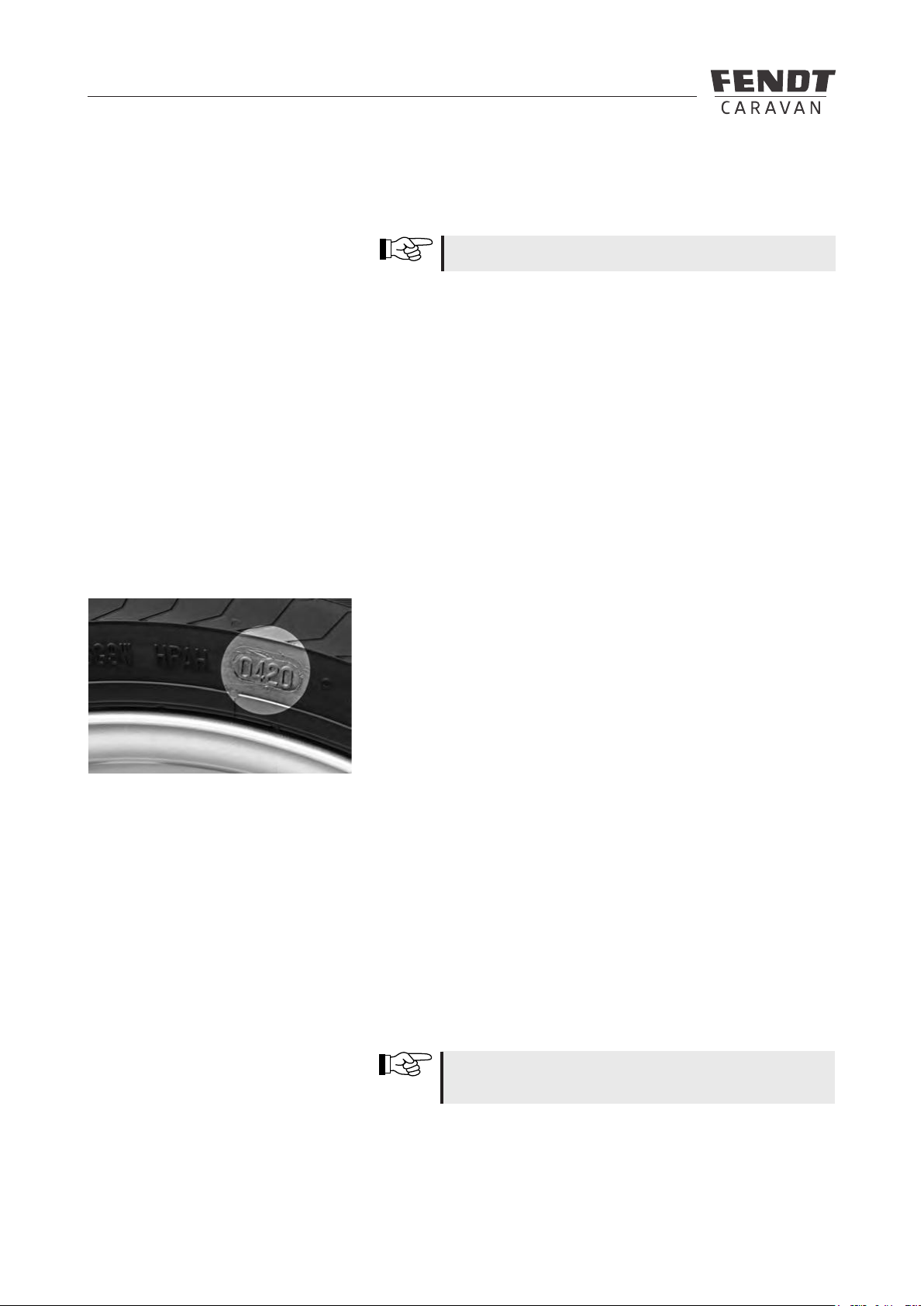
4.3 Prole depth and age of tires .......................................................................................................... 20
4.4 Rims ................................................................................................................................................20
4.5 Changing the tire .............................................................................................................................22
5 Exterior structure
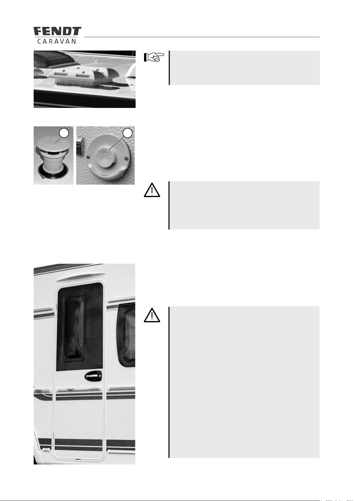
5.1 Ventilation and De-aerating .............................................................................................................24
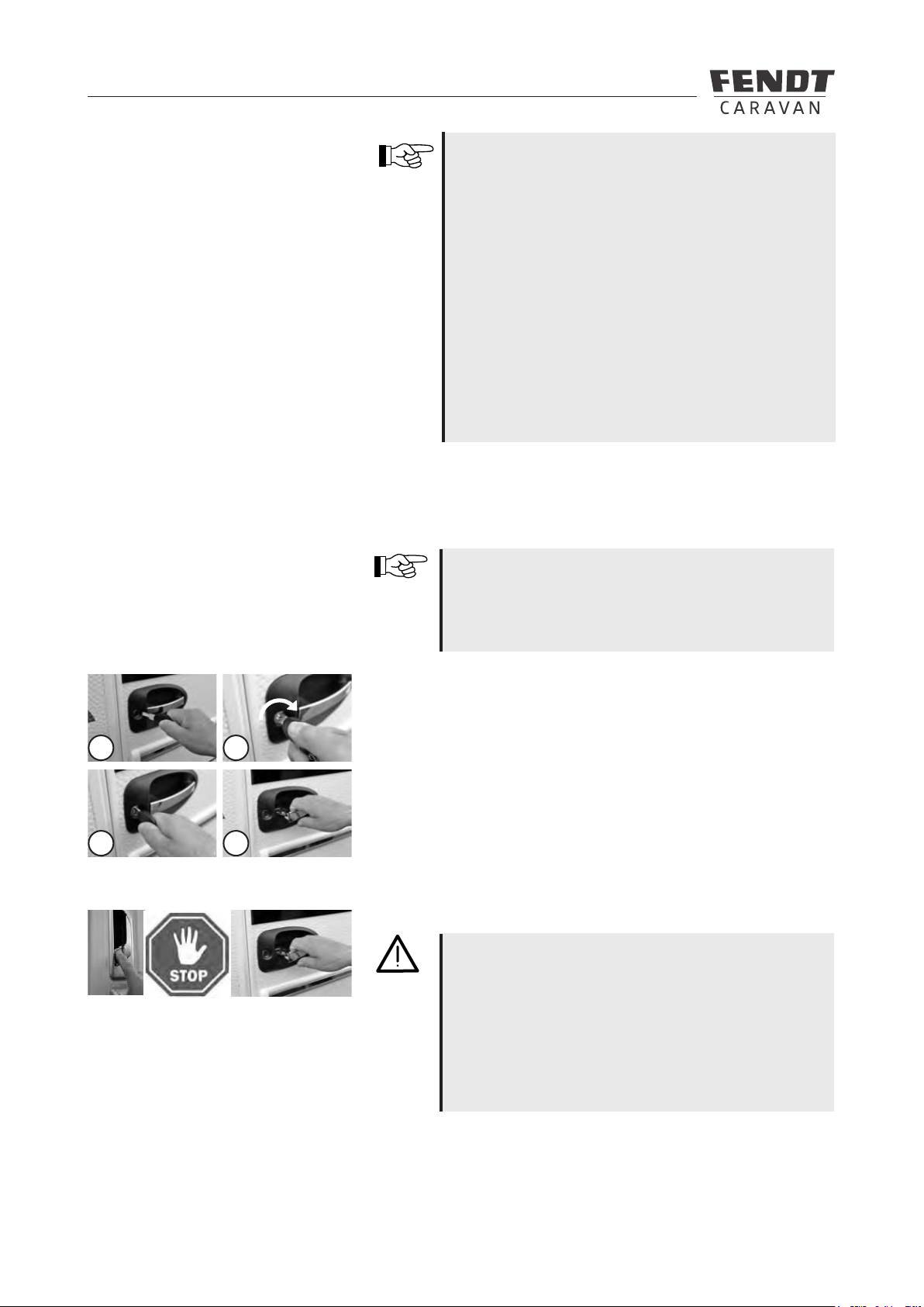
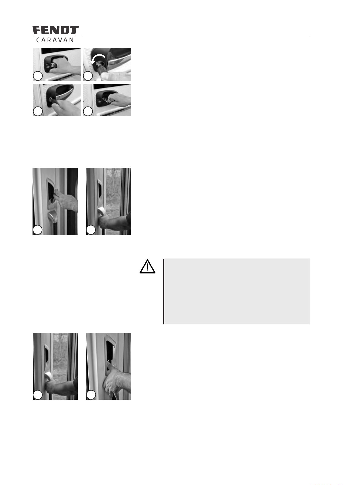
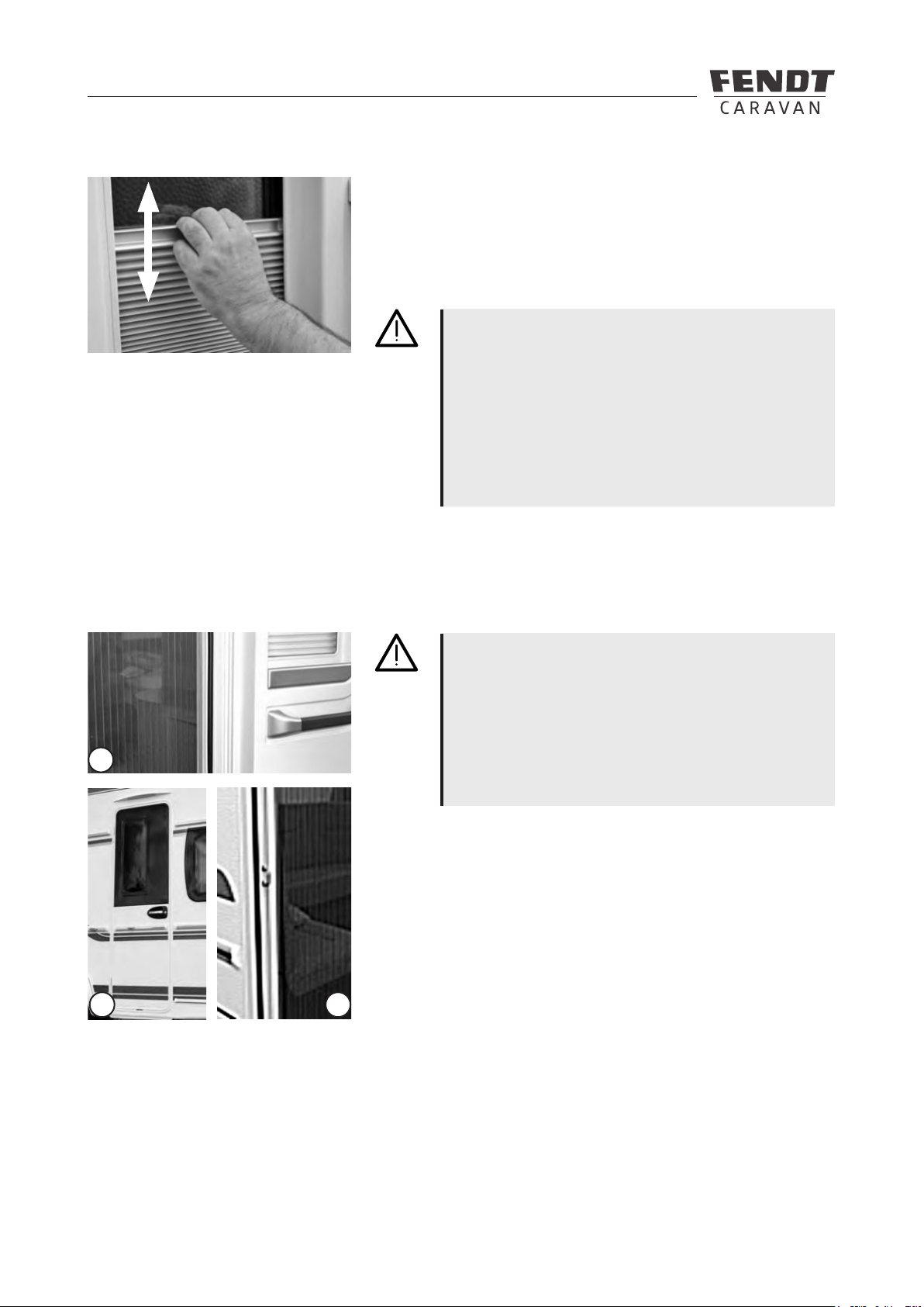
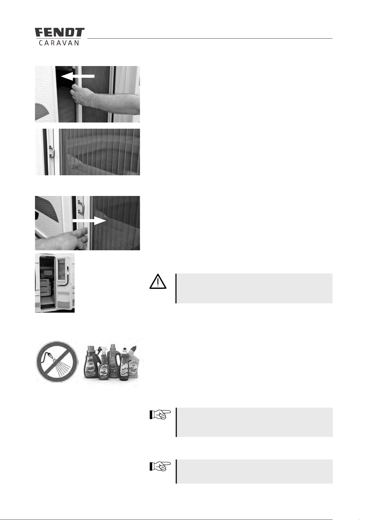
5.2 External entry ..................................................................................................................................25
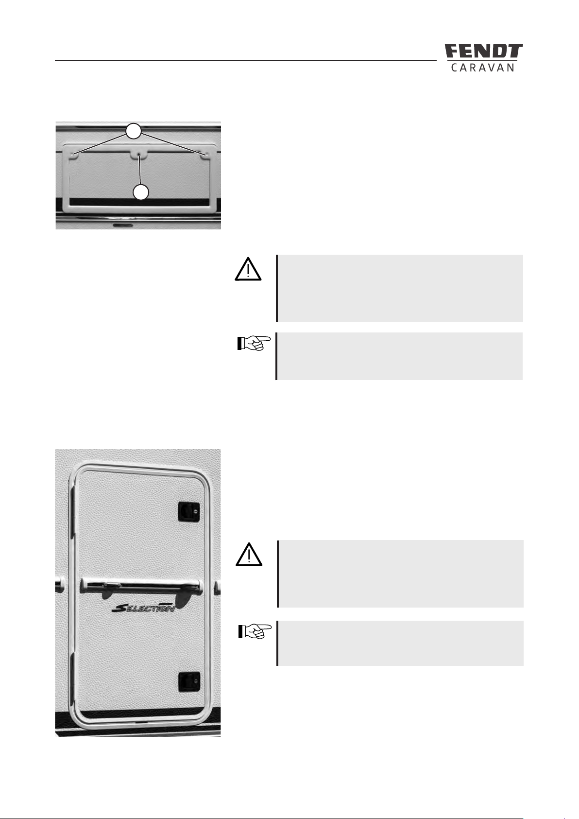
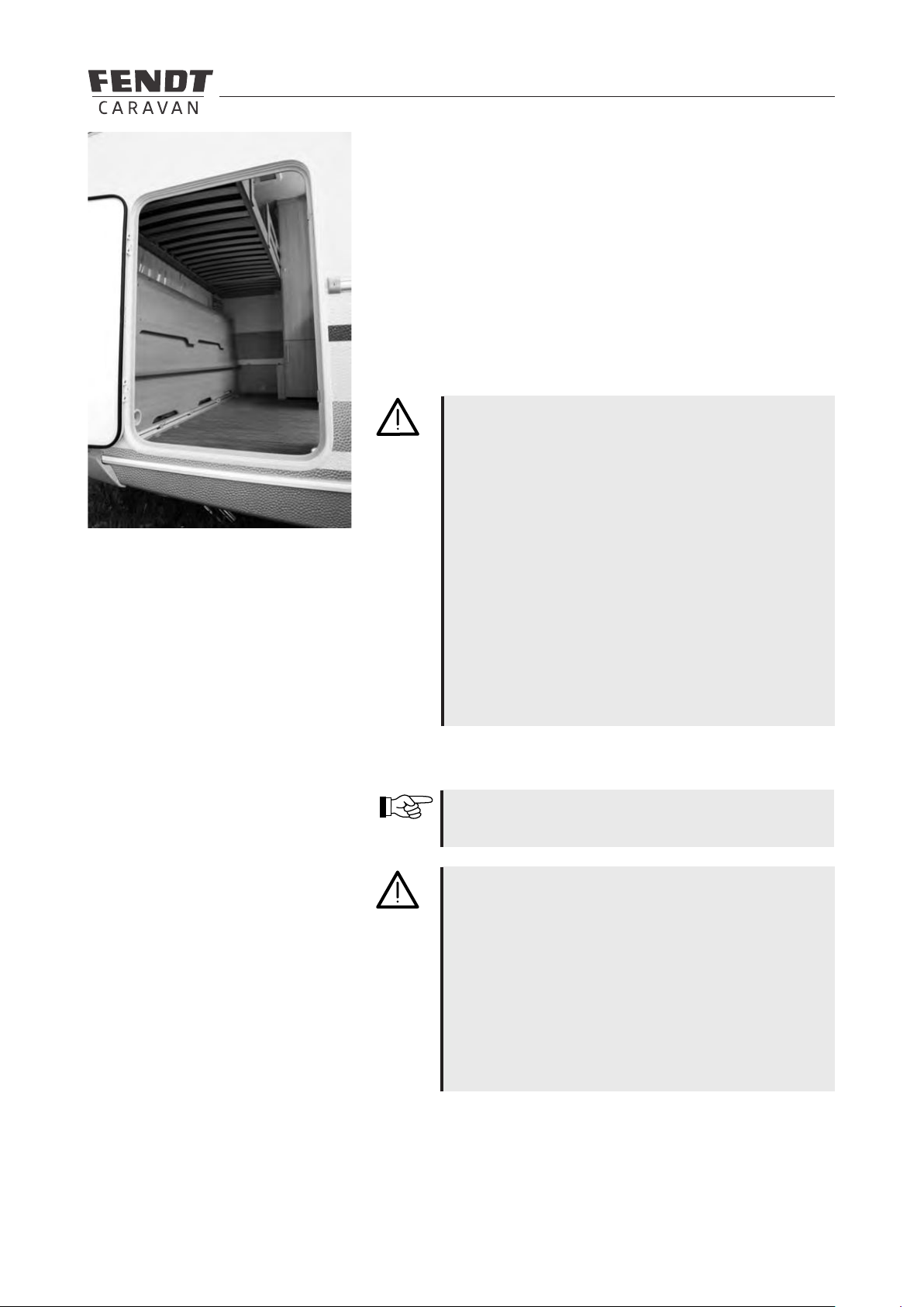
5.3 Service ap .....................................................................................................................................30
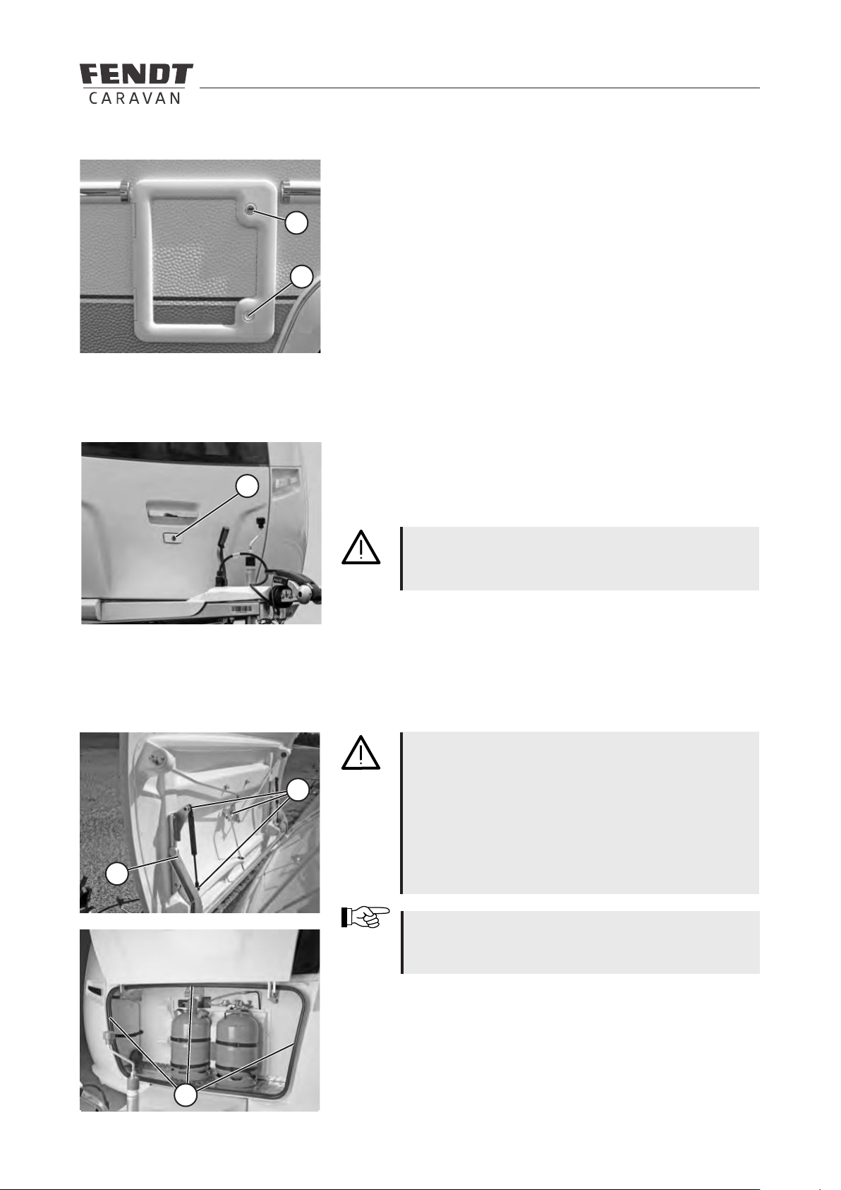
5.4 Toilet ap ......................................................................................................................................... 31
5.5 Gas-bottle container ap ................................................................................................................31
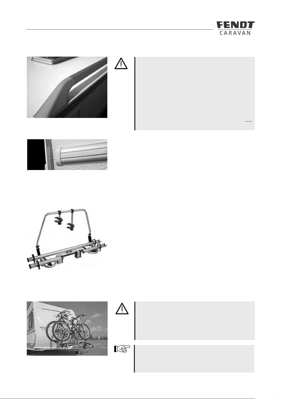
5.6 Roof and roof rail ............................................................................................................................32
5.7 Guide rail for outer tent ..................................................................................................................32
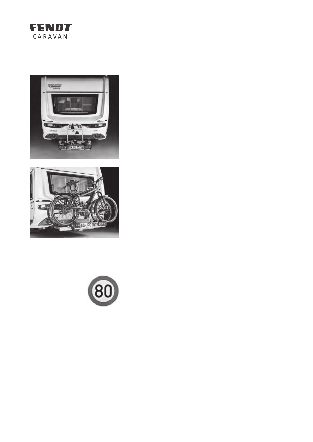
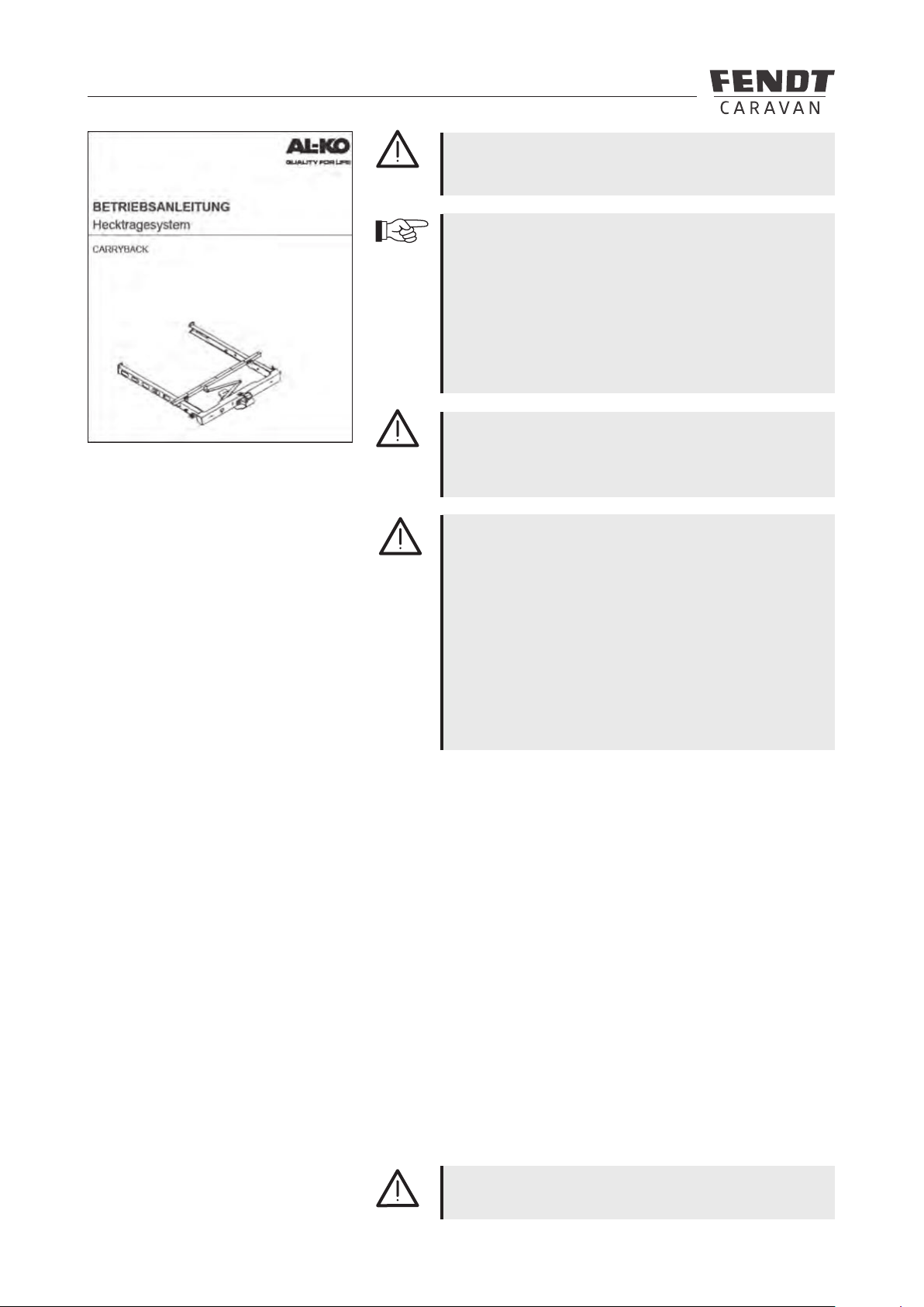
5.8 Bicycle carrier .................................................................................................................................32
5.8.1 Rear-mounted CARRYBACK bicycle carrier ..................................................................................33
5.9 Subsequent installation of an awning .............................................................................................34
6 Interior structure
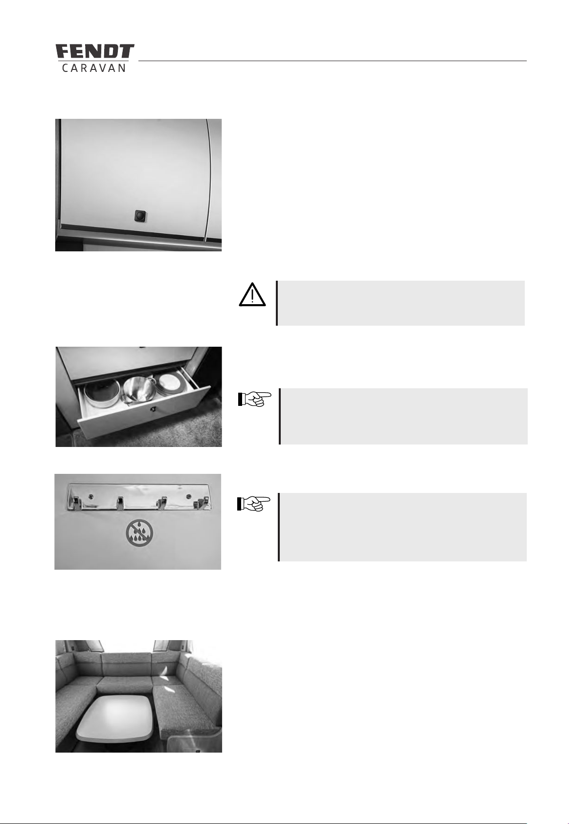
6.1 Doors, aps, drawers and kitchen worktop ....................................................................................35
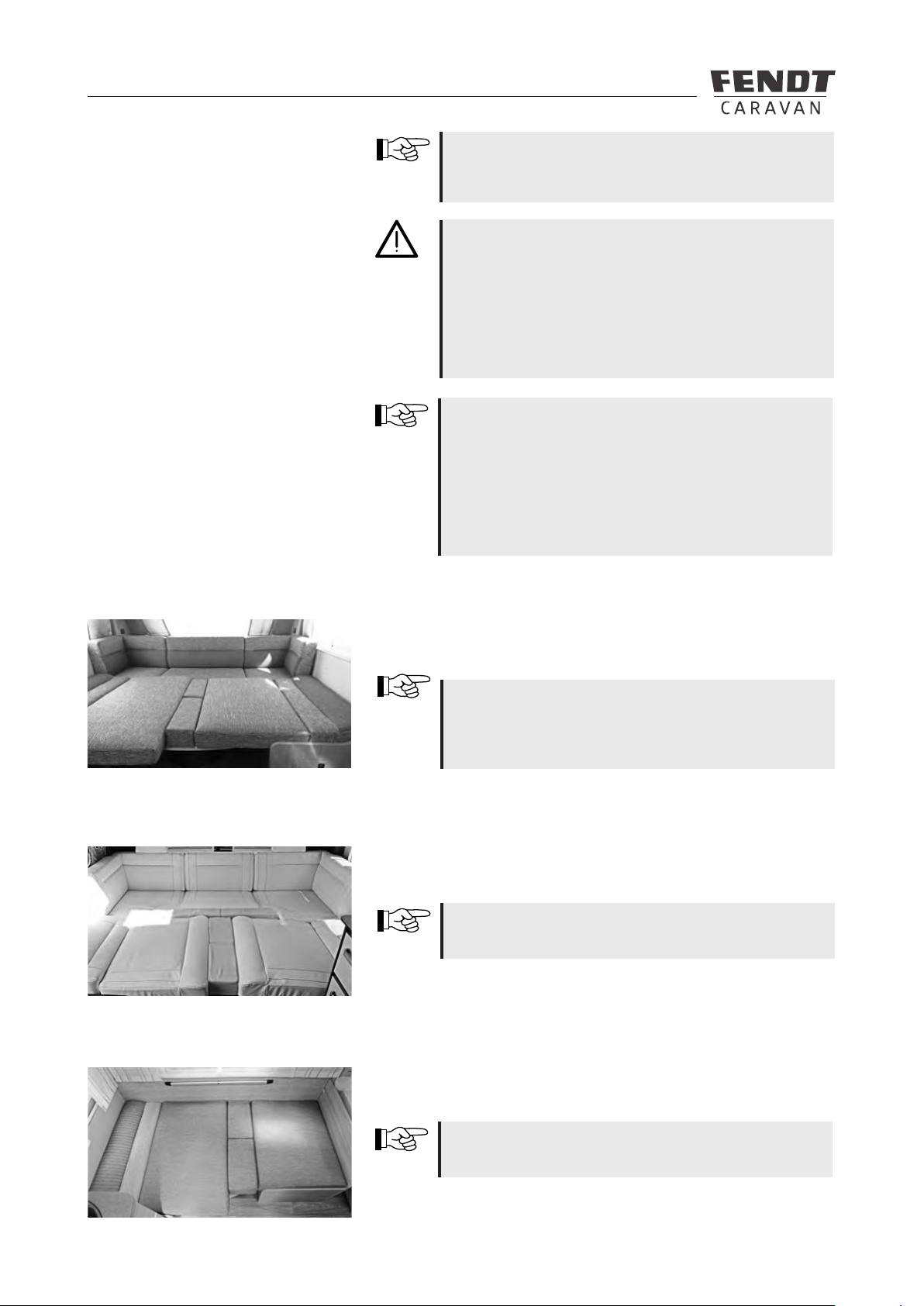
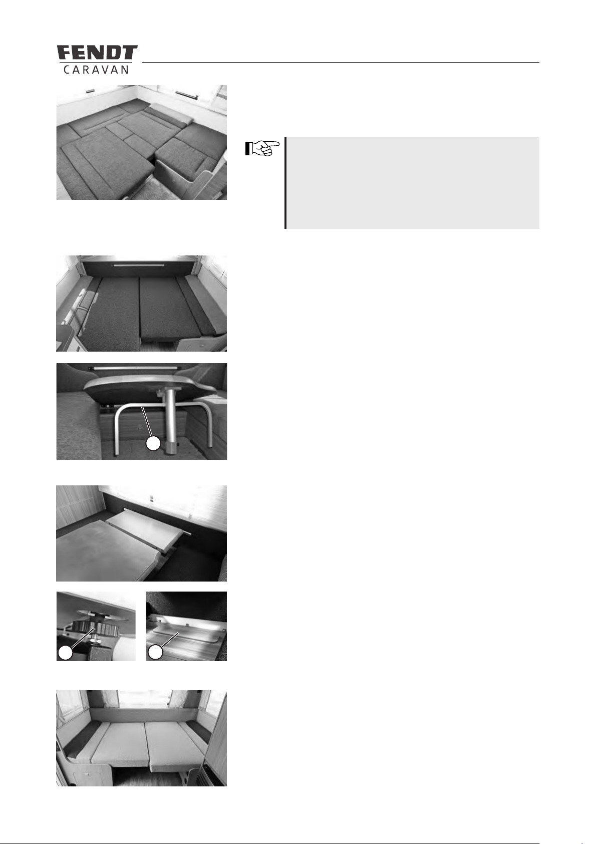
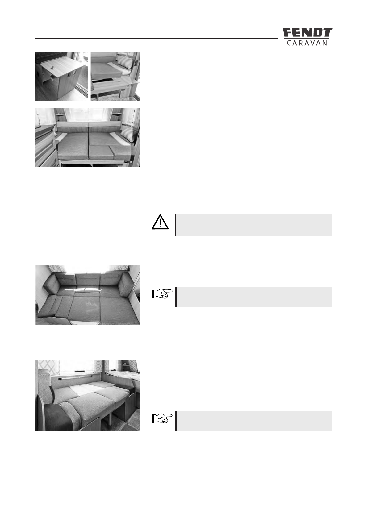
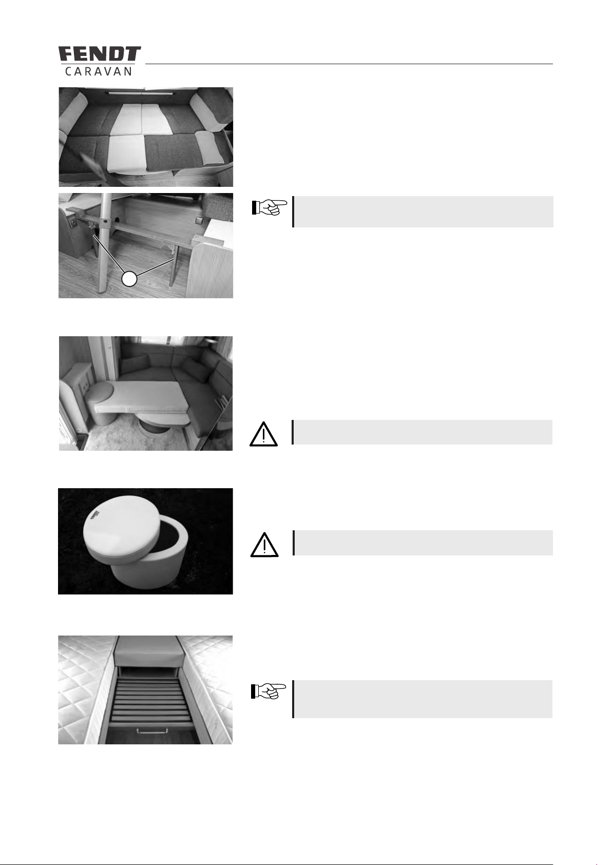
6.2 Converting the seating arrangement into a bed .............................................................................35
6.3 Bunk beds ....................................................................................................................................... 40
6.4 Windows .........................................................................................................................................42
6.5 Roof bonnets...................................................................................................................................42
7 Installation of electrical devices
7.1 Safety tips .......................................................................................................................................43
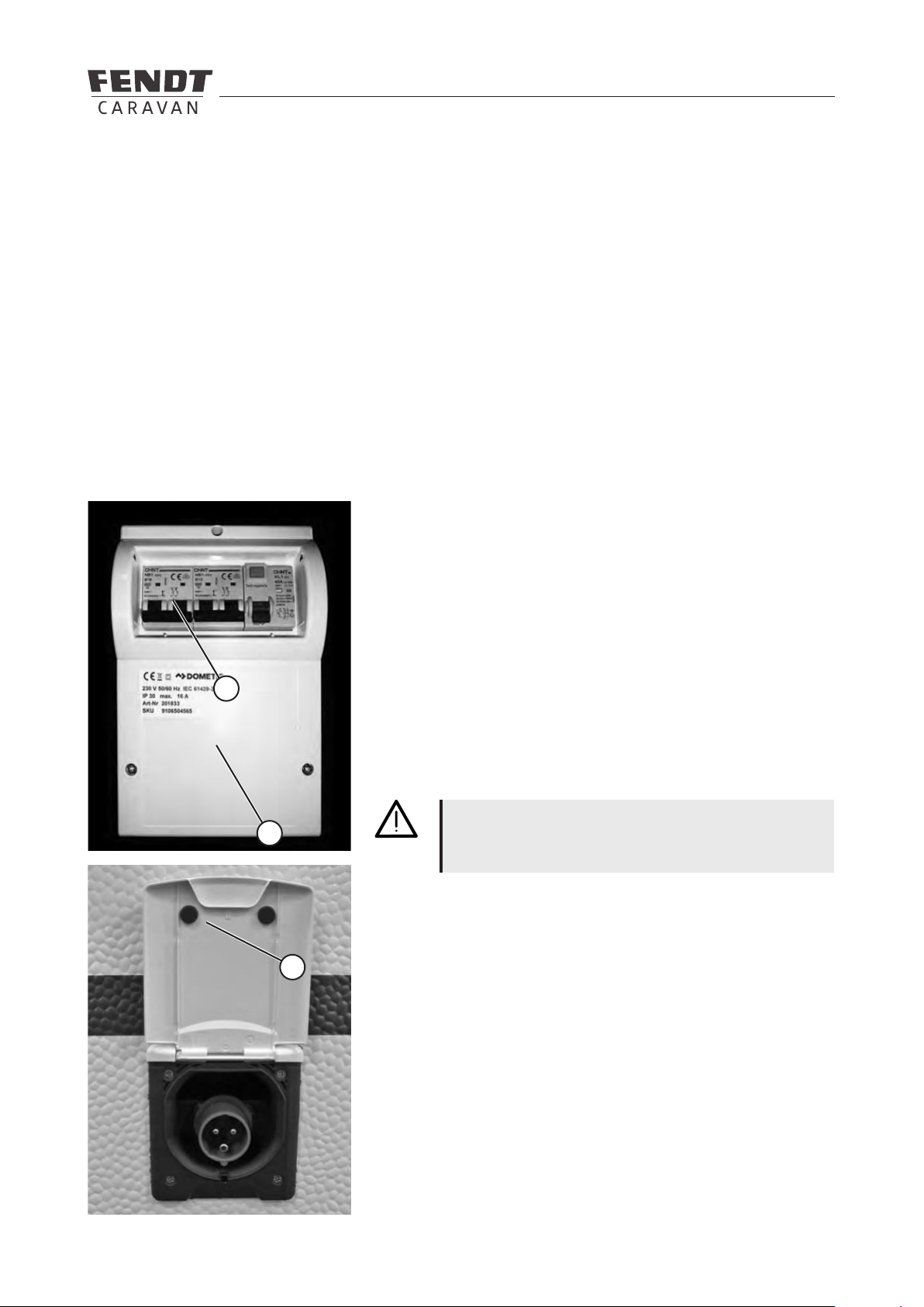
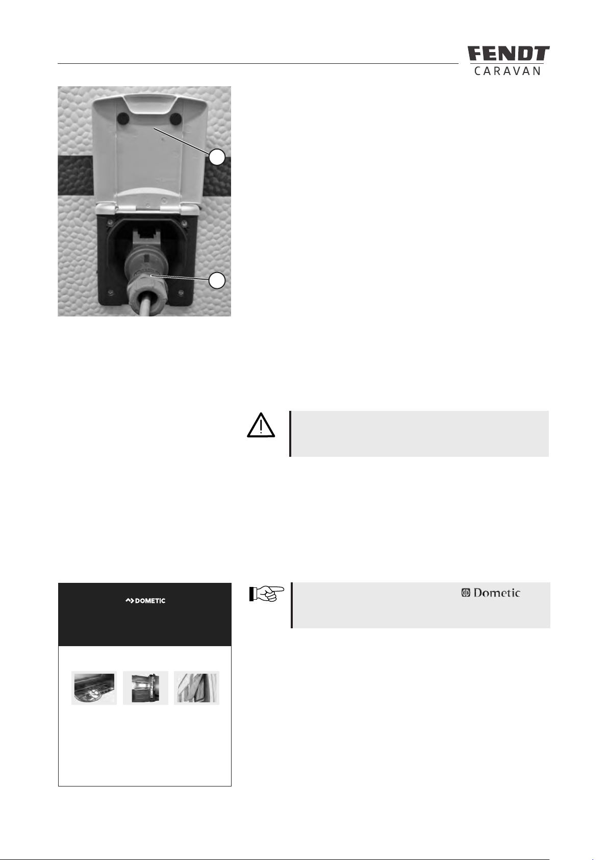
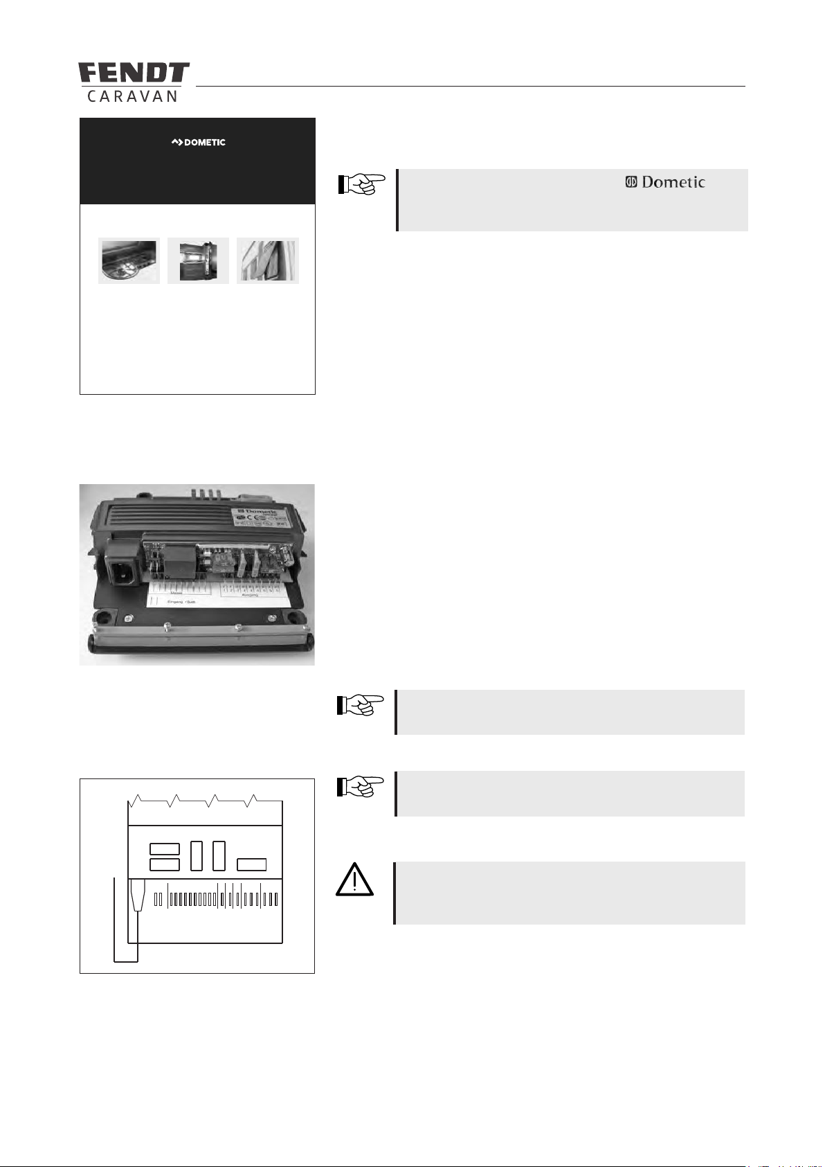
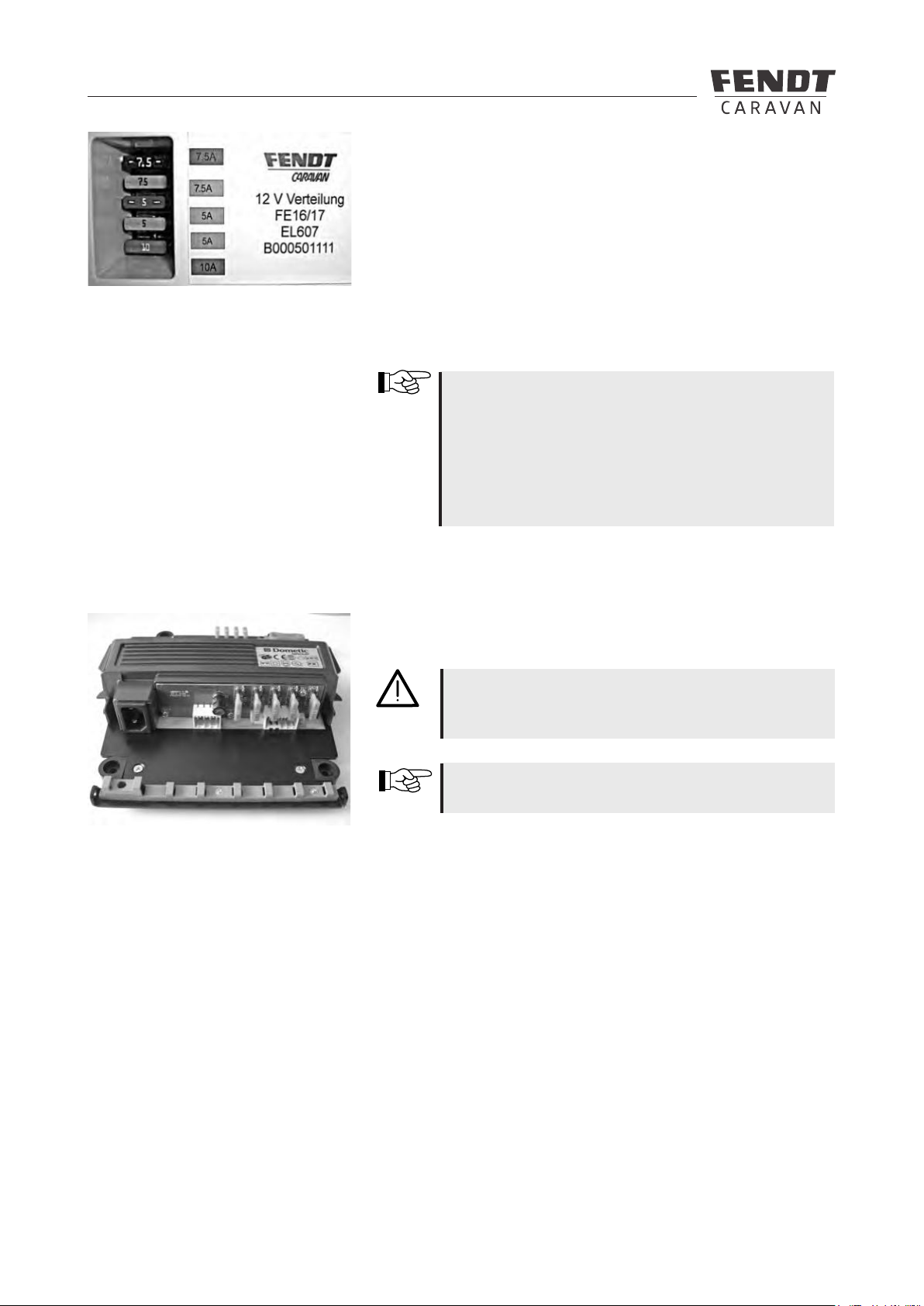
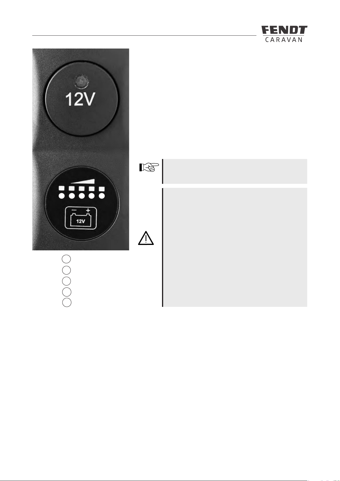
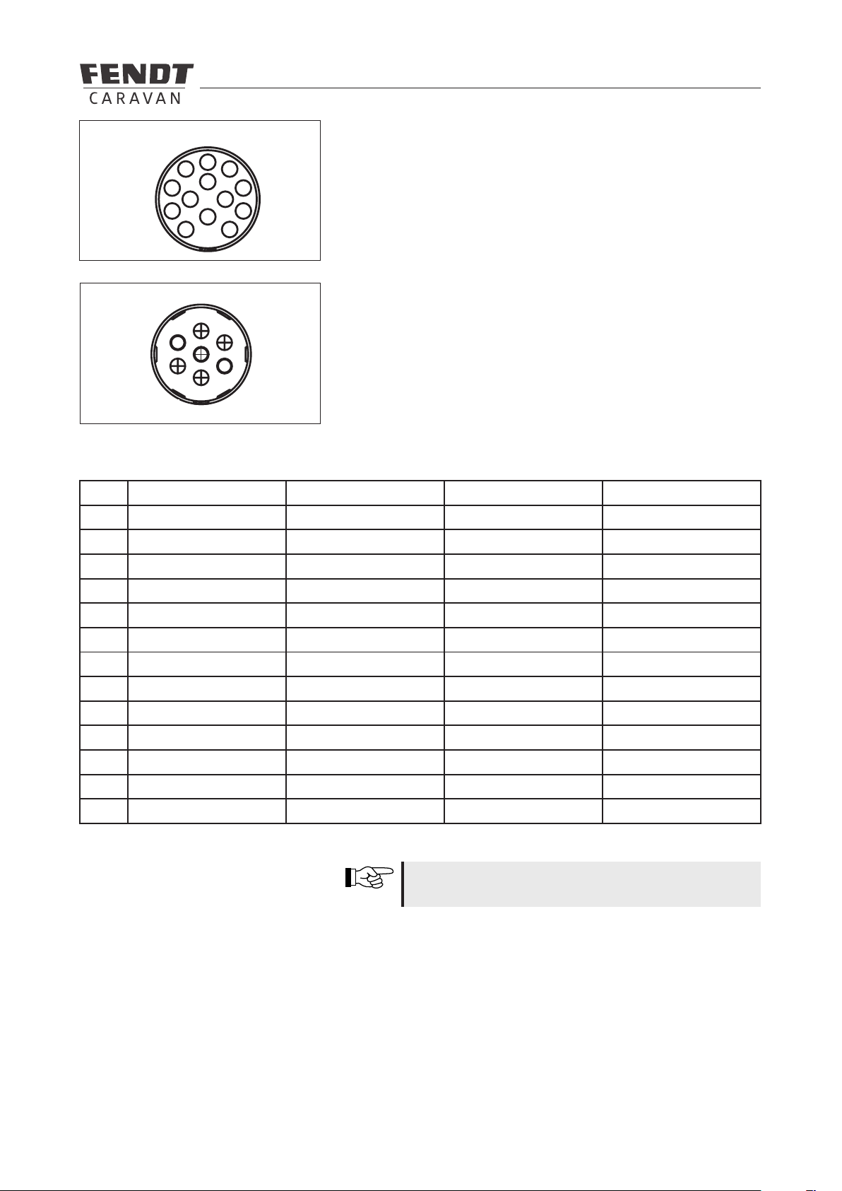
7.2 Electrical supply .............................................................................................................................. 43
7.3 Control panel ...................................................................................................................................47
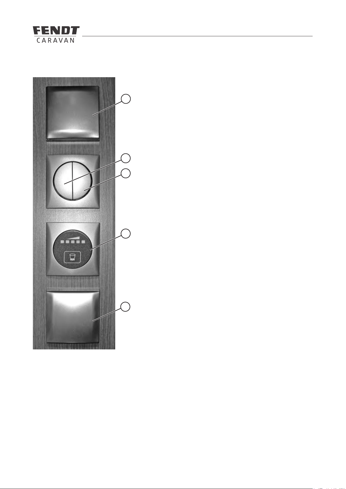
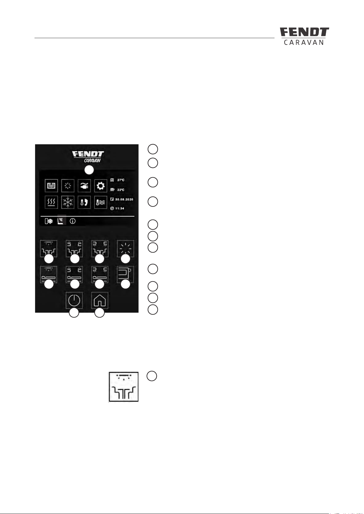
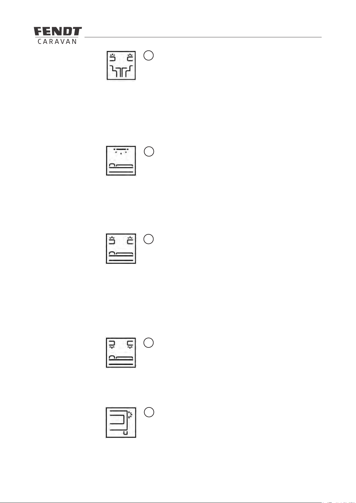
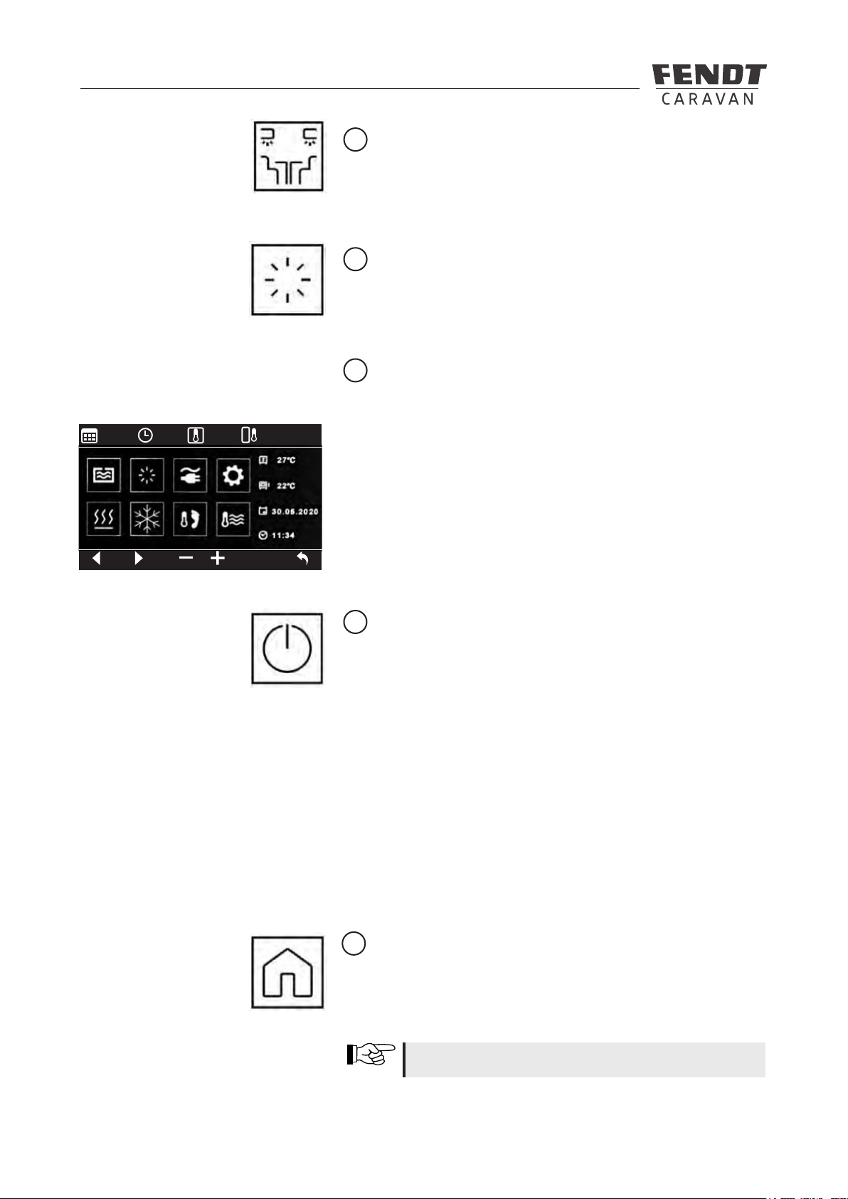
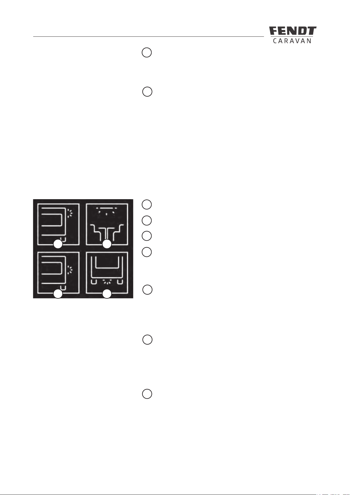
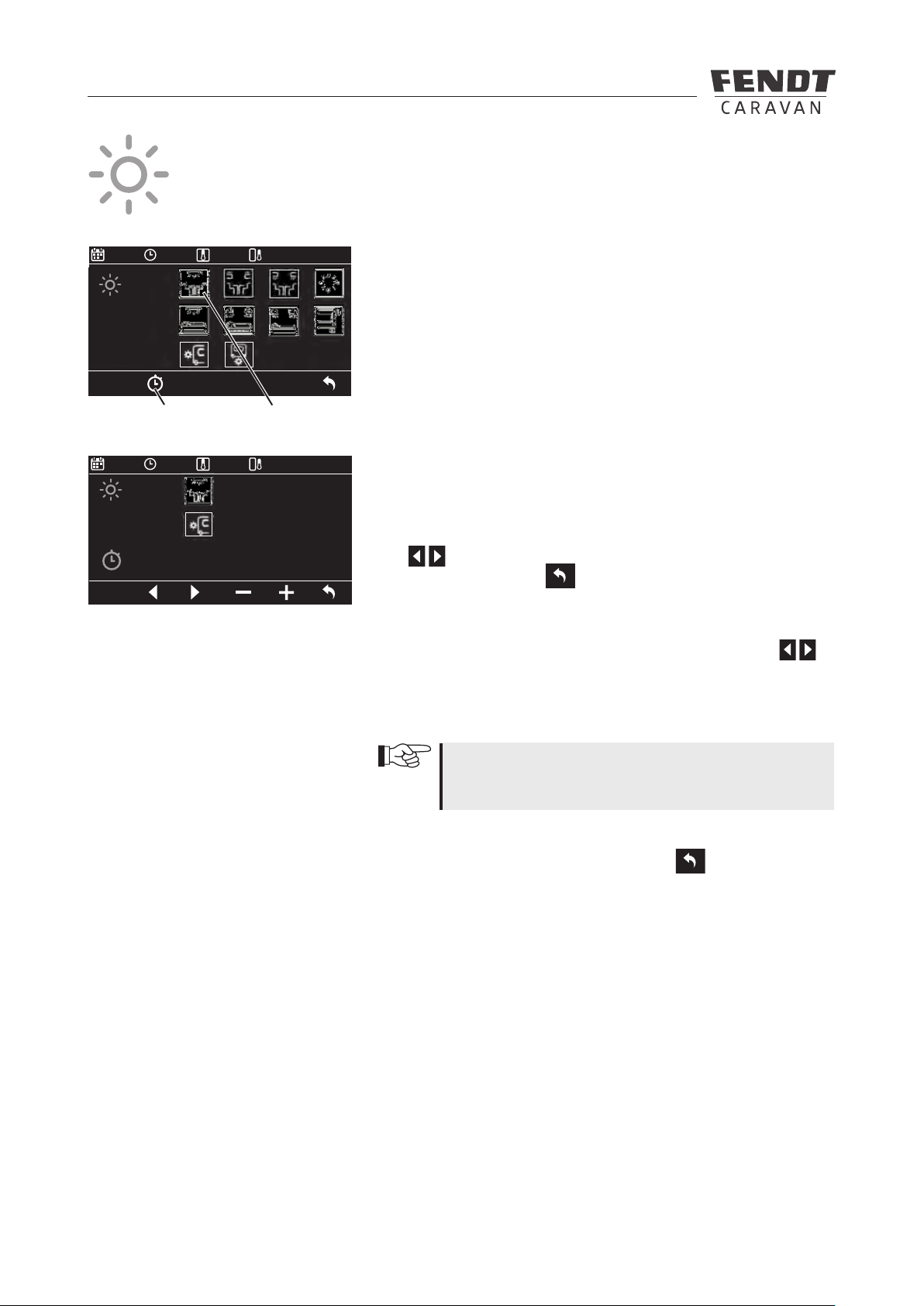
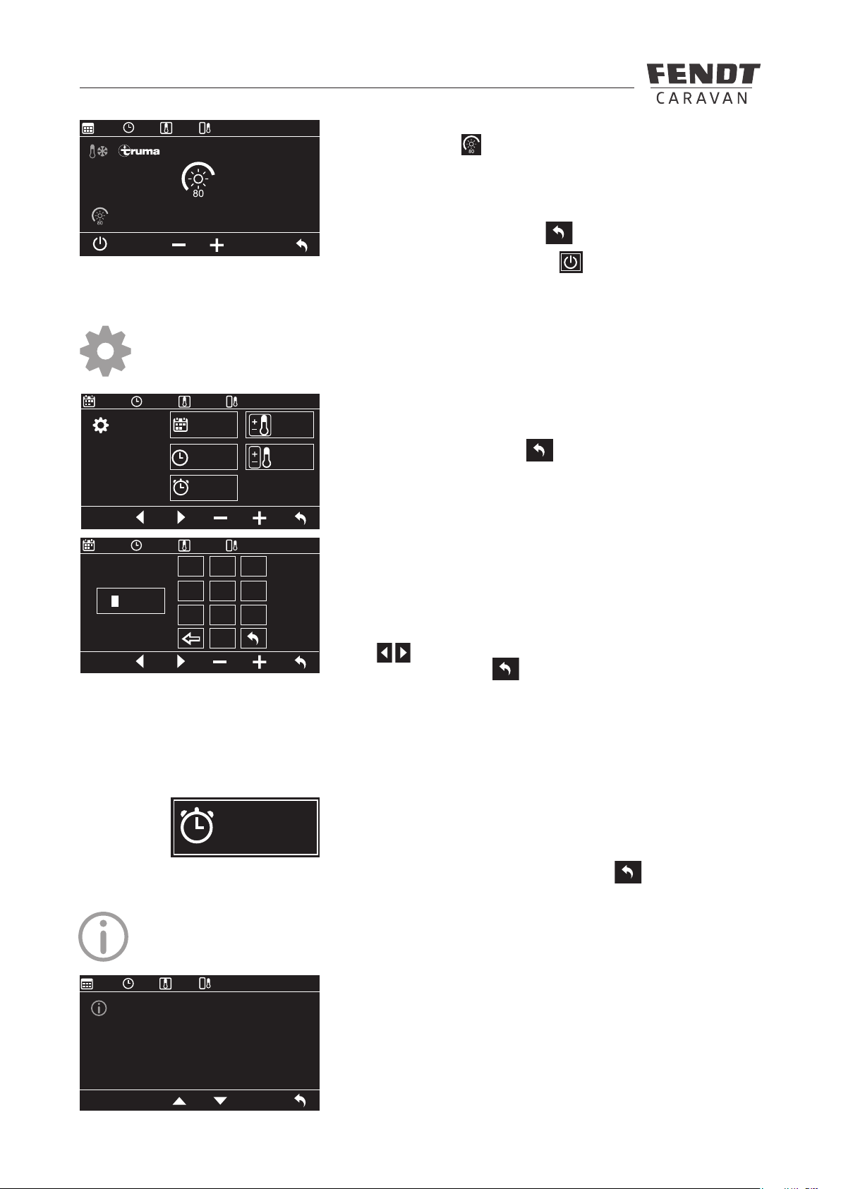
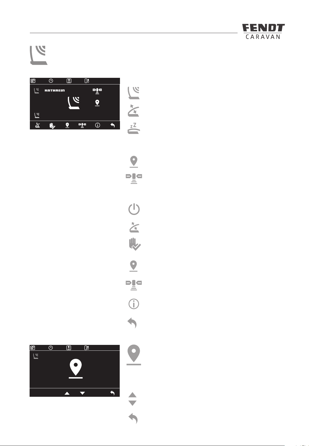
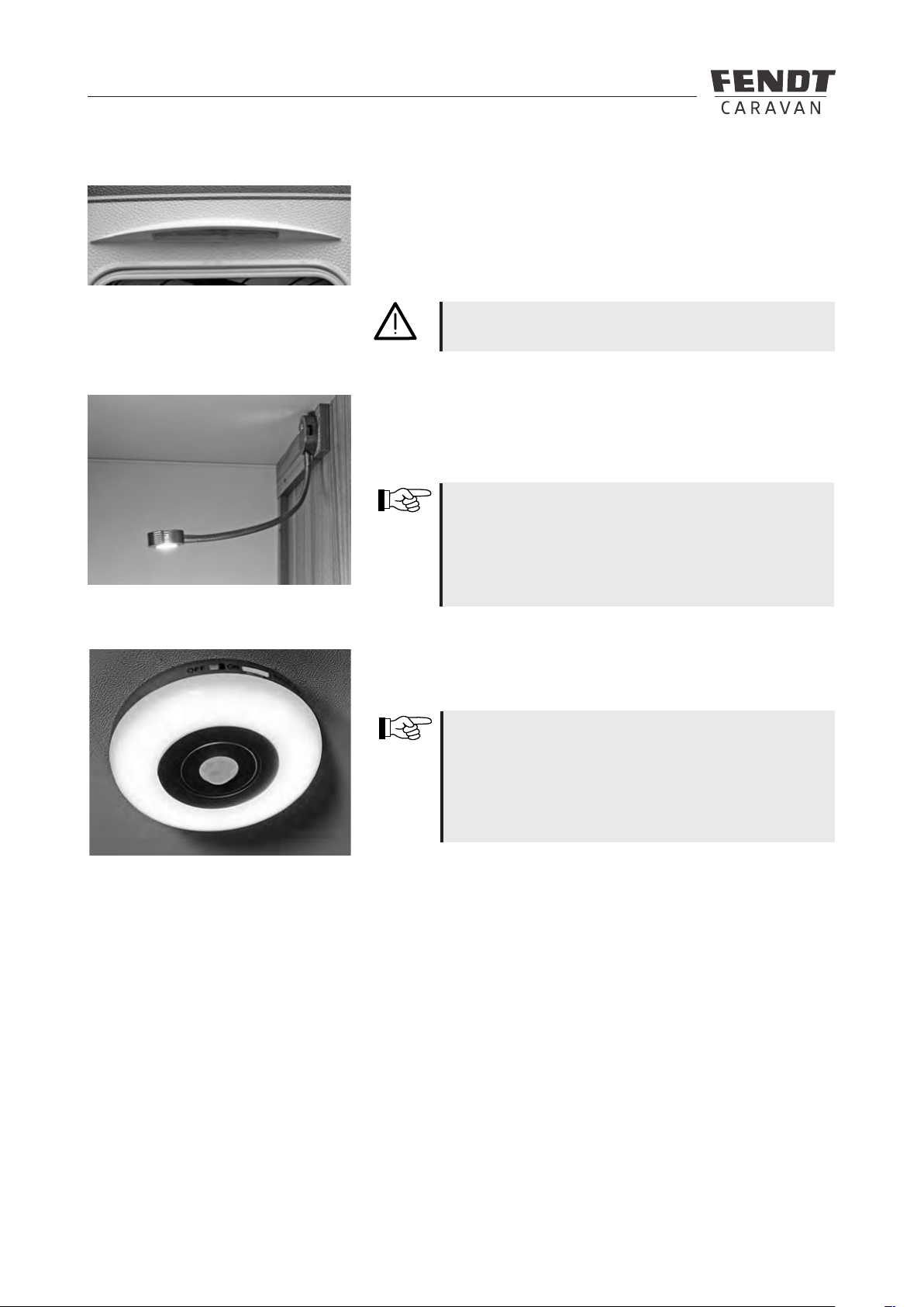
7.4 Lighting control system with switch/touch panel ............................................................................48
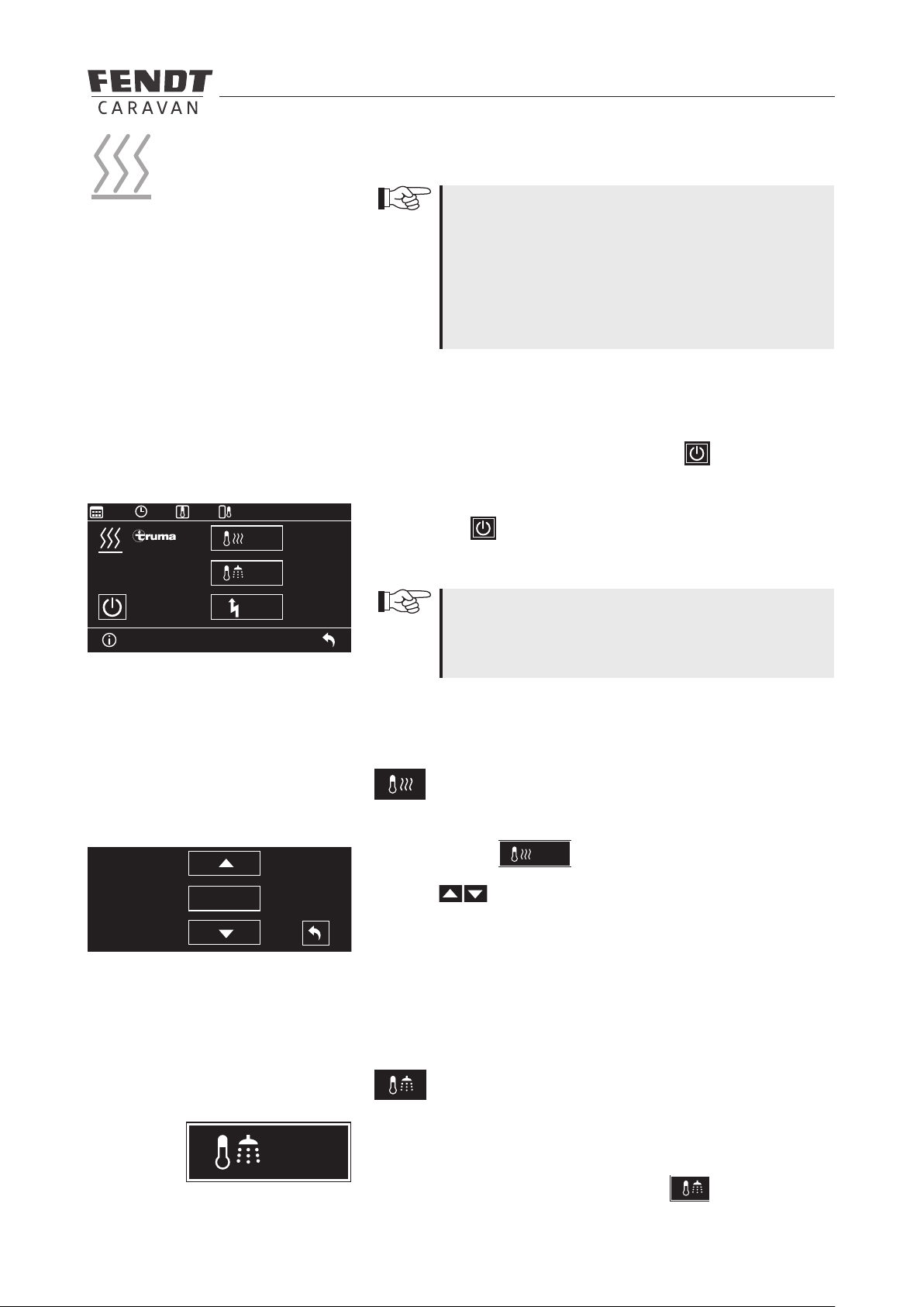
7.5 Truma-iNet-System ......................................................................................................................... 68
7.6 Circuit diagram for lighting in the vehicle ........................................................................................71
7.7 Lights in the caravan requiring extra switching ..............................................................................74
7.8 Electrical oor temperature control system ...................................................................................75
7.9 Microwave ....................................................................................................................................... 76
Table of Contents