514356
3
Verklein
Vergroot
Pagina terug
1/68
Pagina verder
EN INSTALLATION AND USER GUIDE
ES MANUAL DE INSTALACIÓN Y UTILIZACIÓN
NL INSTALLATIE- EN GEBRUIKSGIDS
Cooking hob
Placa de cocción
Kookplaat
2
As part of our commitment to constantly improve our products, we reserve the right to alter
their technical, functional and/or aesthetic characteristics as part of their continuous
development.
IImmppoorrttaanntt nnoottee
: Please read this Installation and User Guide carefully before installing
and using the appliance, as this will help you to quickly familiarise yourself with its
operation.
TABLE OF CONTENTS
Safety guidelines
___________________________________________
70
Caring for the environment
__________________________________
71
Description of your appliance
________________________________
72
1 / INSTALLING YOUR APPLIANCE
Choice of location
__________________________________________
73
Fitting
___________________________________________________
73
Flush Fitting recommendations
_______________________________
74
Electrical connection
_______________________________________
75
Gas connection
____________________________________________
76
Changing the gas supply
____________________________________
78
2 / USING YOUR APPLIANCE
Description of the surface control panel
_______________________
83
Switching on the gas burners
________________________________
84
Suitable cookware for gas burners
____________________________
85
3 / REGULAR CARE OF YOUR APPLIANCE
Caring for your appliance
____________________________________
86
4 / SPECIAL INSTRUCTIONS, TROUBLESHOOTING
During use
________________________________________________
87
5 / COOKING CHART
Gas cooking guide
_________________________________________
88
6 / SOME RECOMMENDATIONS
___________________________________
88
7 / AFTER-SALES SERVICE DEPARTMENT AND CUSTOMER RELATIONS
Service calls
______________________________________________
89
3
EN
4
SAFETY GUIDELINES
SAFETY GUIDELINES
This cooking hob has been designed for
private domestic use.
This appliance must be installed in
compliance with currently applicable
regulations and used only in a well-ventilated
location. Consult this guide before installing
and using your appliance.
Never leave the appliance unattended when
in use.
These cooking hobs are intended solely for
cooking food and drinks and do not contain
any asbestos-based materials.
This appliance is not connected to a
combustion by-product disposal system. It
must be installed and connected in
compliance with all applicable laws. Special
attention should be given to applicable
ventilation regulations.
Do not store cleaning
PRODUCTS or
FLAMMABLE PRODUCTS (aerosol cans or
pressurised containers, as well as papers,
cookbooks, etc.) in the cabinet beneath your
cooking hob.
— If you use a drawer under the hob, avoid
using it to store heat sensitive items (plastic,
papers, aerosol cans, etc.).
Your hob must be disconnected from the
power supply (electricity and gas) before
undertaking repair work.
If you plug electrical appliances into a plug
socket which is within close proximity of the
hob ensure that any wires do not contact the
cooking zones.
As a safety measure, remember to shut-off
the mains gas supply tap or the
butane/propane gas cylinder tap (whichever
is applicable).
The CE compliance mark is affixed to these
hobs.
Installation should only be undertaken by
qualified fitters and technicians.
Before installation, make sure that the local
distribution conditions (gas type and
pressure) and the settings on the appliance
are compatible.
This appliance is not intended to be used
by persons (including children) with reduced
physical, sensory or mental abilities, or those
lacking experience or awareness, unless they
are supervised by someone responsible for
their safety or they have received suitable
training in its operation from the said person.
Children must be supervised to prevent them
from playing with the appliance.
This unit is not intended to be operated
using an external timer or a separate remote
control system.
This hob is compliant with standard
EN 60335-2-6 relating to the heating of
cabinets and the Class 3 standard with regard
to installation (as per standard EN 30-1-1).
Warning
The required hob settings are written
on a sticker inside the instruction guide
pouch and on the packaging.
In order to easily locate any reference
information relating to your appliance, we
recommend that it is noted on the “After-
Sales Service Department and Customer
Relations” page (this page also explains
where this information can be found on your
appliance).
CAUTION: if a crack appears in the surface,
disconnect the appliance from the power
supply to prevent any risk of electric shock.
For the following references : CFI-4GLSTANAT* - CFI-3GLSTANAT*
your hob is delivered set-up for natural gas.
For the following references : CFI-4GLSTABUT* - CFI-3GLSTABUT* - 2MCF-
2GSAXBUT* your hob is delivered set-up for butane gas.
CARING FOR THE ENVIRONMENT
— This appliance’s packing materials can be
recycled. Please recycle the packaging and
share in the protection of the environment by
depositing them in municipal containers
provided for this purpose.
— Your appliance also contains
many recyclable materials. It is
therefore marked with this logo to
indicate that used appliances must
not be mixed with other waste. The
manufacturer will organise
recycling of the appliances in
optimum conditions, in accordance with
European directive EC/2002/96 governing
electrical and electronic equipment waste.
Consult your local authority or your retailer to
find the drop-off points for used appliances
which are nearest to your home.
— Thank you for your help in protecting the
environment.
CARING FOR THE ENVIRONMENT
5
EN
6
DESCRIPTION OF YOUR APPLIANCE
DESCRIPTION OF THE HOB
Hob model: 4 gas burners
with super fast burner
Hob model: 3 gas burners
with triple ring burner
Hob model: 2 gas burners
with super fast burner
A
B
Burner cover
Burner head
Injector
C
D
E
Spark plug
Thermocouple
Control Knob
F
G
H
Tap
Gasket
Note
This Installation and User guide covers several models. There may be minor differences
in details and fittings between your appliance and the descriptions provided.
D
E
A
B
F
H
G
C
1/ INSTALLING YOUR APPLIANCE
CHOICE OF LOCATION
Your appliance must be flush fitted into a
support cabinet surface which is at least 3 cm
thick and is manufactured from heat resistant
material or covered in a heat resistant
coating.
A minimum distance of 30 cm either side of
the hob should be free from any obstructions
(cabinet or panel) which could hinder safe
handling of cooking utensils.
If a horizontal divider wall is positioned under
the hob, it must be located between 10 cm and
15 cm from the top of the work surface. In any
event, do not store aerosol cans or
pressurised containers in any compartments
located under the hob (refer to the
Safety
Recommendations
) chapter.
FITTING
In order to guarantee the seal between the
hob and the work top, the supplied seal must
be glued into the insert prior to hob
installation:
Refer to the diagram
(Fig. 01)
.
Remove the pan supports, burner covers
and burner heads; noting their positions.
Turn the hob over and carefully place it on
top of the opening in the cabinet to prevent
damage to the knobs and spark plugs.
— In order to guarantee the seal between the
housing and the worktop, stick the foam seal
around the edge of the frame
(Fig. 02
).
49 cm mini
3 cm mini
30 cm mini
56 cm / 26,5 cm
30 cm mini
5,8 cm mini
70 cm mini
Fig. 01
Fig. 02
Housing
Seal
APPLIANCE (60 cm model)
Standard
cabinet
cut-out
Total
dimensions
above
the work
surface
Total
dimensions
below
the work
surface
Width
56 cm
71 cm
55.4 cm
Depth
49 cm
52.2 cm
47 cm
Thickness
depending
on
cabinet
5 cm
5.1 cm
APPLIANCE (30 cm model)
Standard
cabinet
cut-out
Total
dimensions
above
the work
surface
Total
dimensions
below
the work
surface
Width
26.5 cm
29,3 cm
26,3 cm
Depth
49 cm
52,5cm
47,9 cm
Thickness
depending
on
cabinet
5,4 cm
5.1 cm
7
EN
8
A
A
Place your hob in the support cabinet
opening and carefully draw the hob towards
you.
Re-position the burner heads, burner
covers and pan supports on the hob.
Connect the hob to the gas supply (See “Gas
Connection” chapter) and to the power
supply (See “Electrical Connection” chapter).
If you wish, you can immobilise the hob
using the four mounting brackets (supplied
with screws)
(Fig. 02)
to attach them to the
four corners of the housing. You must use the
holes provided for this purpose, according
to the diagram above
(Fig. 02)
.
Stop screwing when the mounting bracket
becomes deformed.
Do not use an electric screwdriver.
Fig. 01
Fig. 03
Screw
FLUSH FITTING RECOMMENDATIONS
Mounting brackets
A
A
Cabinet
1/ INSTALLING YOUR APPLIANCE
Fig. 02
Mounting holes
located using
arrows
A
Fig. 01
Mounting holes
A
Mounting holes
A
A
4 Burner Model
(underside view of the housing)
3 Burner Model
(underside view
of the housing)
2 Burner Model
(underside view of the housing)
A
A
A A
Fig. 01
Mounting bracket
1/ INSTALLING YOUR APPLIANCE
9
EN
ELECTRICAL CONNECTION
Your hob (which is supplied with an H05V2V2-
F type wire) must be connected to the 220-
240 V
~
single phase grid via a standardised
CEI 60083 2-pole + ground electrical outlet
plug or an all-pole cut-off device, in
compliance with the current regulations.
The electrical plug socket must remain
accessible after installation.
TYPE OF CABLE SECTION TO BE USED
H05V2V2F -T90 cable
Ref. After-sales
service: 77x9060
Conductor section
in mm
2
Fuse
220-240 V
~
- 50 Hz
3 conductors
including
1 ground
1
10 A
Warning
The safety wire (green/yellow) is
connected to the appliance’s ground terminal
and must be connected to the installation’s
ground terminal . A 10 amperes fuse must
be used in the installation. If the power cable is
damaged, it must be replaced by a cable or a
special kit which is available from the
manufacturer or their After-Sales Service
Department.
Tip
Using a gas cooking appliance generates
heat and humidity in its local vicinity. Make sure
that your kitchen is well-ventilated: ensure
natural ventilation openings in your home are
unobstructed or install a mechanical ventilation
device (mechanical ventilation hood). Intensive,
prolonged use of the appliance may require
additional ventilation; you can, for example,
open a window or provide more effective
ventilation by increasing the setting on a
mechanical ventilation system, where installed.
(a minimum air flow of 2 m
3
/hr per kW of gas
power is required).
For example : 30 cm - 2 gas burners
Total power : 1.5 + 3.1 = 4.6 kW
4.6 kW x 2 = 9.2 m
3
/h
minimum flow.
10
The gas connection must be installed in
compliance with applicable regulations in the
country of installation.
Gas distributed via natural gas
pipework
For your safety, you can only choose from the
following 3 connection options:
Connection with a rigid copper pipe
with
screw-on mechanical connectors (G1/2 gas
standard mark). Connect directly to the end of
the elbow fitted on the appliance.
Connection with a flexible metal hose
(stainless steel)
with screw-on mechanical
connectors
(compliant with standard NF D 36-
121) with lifetime service guarantee
(Fig. A).
Connection with a reinforced rubber
hose
with screw-on mechanical
connectors
(compliant with the NF D 36-103 standard)
with 10 year service life guarantee
(Fig. B).
Warning
If you have to change the direction
of the elbow fitted on the appliance
when connecting your hob’s gas supply:
Change the sealing washer.
Tighten the elbow nut but do not
exceed 17 N.m. torque.
GAS CONNECTION
Preliminary comments
If your hob is installed above an oven or if the proximity of other heating elements risks
overheating the connection, you must insulate the cable in a rigid pipe.
If a flexible hose or pipe (in the case of butane gas) is used, it must contact a moving part of the
cabinet or traverse a location likely to become blocked.
Fig. A
Fig. B
1/ INSTALLING YOUR APPLIANCE
11
EN
Gas supplied by tank or
cylinder (butane/propane)
For your safety, you can only choose from the
following 3 connection options:
Connection with a rigid copper pipe
with
screw-on mechanical connectors (G1/2 gas
standard mark). Connect directly to the end of
the elbow fitted on the appliance.
Connection with a flexible metal hose
(stainless steel)
with screw-on mechanical
connectors (compliant with standard
NF D 36 121) with lifetime service guarantee
(Fig. 01).
Connection with a reinforced rubber
hose
with screw-on mechanical
connectors
(compliant with the NF D 36-112 standard)
with 10 year service life guarantee (Fig. 02).
A
B
Sealing washer (not provided)
Adaptor (not provided)
Hose clip (not provided)
C
Warning
All flexible pipes and hoses with a
limited service life must have a maximum
length of 2 meters and must be accessible
along their entire length. They must be
replaced before the end of their service life
(indicated on the pipe). Regardless of the
chosen connection type, use soapy water to
ensure that the connection is leaktight once
installation is complete.
In France, you must use a hose or a pipe
bearing the “NF Gaz” stamp .
In an existing system, a flexible pipe fitted
with hose clips (compliant with the XP D 36-
110 standard) with a five year service life
guarantee can be used. In this case an
adaptor must be used and a sealing washer
must be inserted between the adaptor and
the hob’s elbow
(Fig. 03).
Tip
You can obtain the adaptor and the sealing
washer from your After-Sales Service
Department.
Warning
Do not exceed 25 N.m. torque when
tightening the adaptor.
Fig. 01
Fig. 02
Fig. 03
A
B
C
12
1/ INSTALLING YOUR APPLIANCE
CHANGING THE GAS SUPPLY
Proceed as follows every time you change the
gas supply:
Modify the gas connection
Change the injectors
Adjust the hob connections.
Modify the gas connection : refer to the
“Gas Connection” section.
Change the injectors, proceed as follows:
Remove the pan supports, heads and
covers from all burners.
For a 3-ring burner :
Use a 7mm type pipe spanner (not
supplied).
For other burners:
Use the spanner provided.
Unscrew and remove the injectors located
in the base of each crucible
(Fig. 01).
Replace with the corresponding gas
injectors, in compliance with the injector
positioning markers and the gas
characteristics table at the end of this chapter;
proceed as follows:
First, manually tighten until the injector
locks into place.
Fully connect the spanner onto the injector.
Draw a line on the burner plate using a
pencil where shown
(Fig. 02).
Turn the spanner clockwise until the line
appears on the opposite side
(Fig. 03).
Warning
Exceeding this limit may damage the
product.
Fig. 02
Fig. 03
Line
Line
Fig. 01
Spanner
Injector
Crucible
Warning
- For the following references : CFI-
4GLSTANAT* - CFI-3GLSTANAT*, your hob
is delivered set-up for
nnaattuurraall ggaass
.
- For the following references : CFI-
4GLSTABUT* - CFI-3GLSTABUT* - 2MCF-
2GSAXBUT*, your hob is delivered set-up for
bbuuttaannee ggaass
.
The injectors which are needed to change
the gas can be found in the installation
guide pouch.
Warning
Exceeding this limit may damage the
product.
-
Reposition the burner heads, burner covers
and pan supports on the hob.
Tip
Each time you change the gas supply,
tick the box corresponding to the new gas
level on the label found in the instruction
guide pouch.
Refer to the corresponding “Gas
Connection” section.
Spanner
Spanner
1/ INSTALLING YOUR APPLIANCE
13
EN
Adjust the hob connections: these are
located underneath the control knobs
(Fig. 04)
.
Proceed one tap at a time.
Remove the control knobs and the gaskets
by pulling upwards.
- Switching from natural gas to
butane/propane
-
Using a small flat-head screwdriver, fully
tighten the brass burner power screws
(yellow)
(Fig. 05),
in a clockwise direction.
-
Replace the gaskets and the control knobs,
noting their direction and ensuring that the
control knobs are fully inserted.
- Switching from butane/propane to natural
gas
-
Unscrew the brass (yellow) burner power
screws
(Fig. 05)
, using a small flat-head
screwdriver, turn twice anti-clockwise.
-
Replace the control knob.
-
Ignite the burner in maximum heat mode,
then turn down to reduced heat mode.
-
Remove the control knob again, then turn
the burner power screw clockwise until it
reaches the lowest possible setting without
extinguishing the flame.
-
Replace the gasket and control knob.
-
Repeatedly change from the maximum to
the minimum flow rate: the flame must not go
out ; if it does, unscrew the burner adjustment
screw to achieve good flame retention during
these changes.
-
Replace the burner heads, burner covers
and pan supports on the hob.
Sealing ring
Tap
Fig. 04
Fig. 05
Tap axis
Burner power
adjustment screw
Control Knob
14
1/ INSTALLING YOUR APPLIANCE
• Injector markings
The diagram opposite shows where the
injectors are positioned on your appliance
according to the type of gas used.
Each number is marked on the injector.
INJECTOR MARKINGS
4 gas burner hob with triple ring
3 gas burner hob with triple ring
62
For example:
injector marking 62
Natural Gas
Butane/Propane
Gas
2 gas burner hob
Natural Gas
Butane/Propane Gas
137
63
Natural Gas
Butane/Propane
Gas
94
1R
63
62
7R
45
88A
45
092/55B/092
092/55B/092
60/37/60
60/37/60
137
94
88A
62
1/ INSTALLING YOUR APPLIANCE
15
EN
• Injector markings
TRIPLE RING BURNER INJECTOR MARKINGS
Natural Gas
Butane/Propane Gas
092
60
55B
37
092
60
16
1/ INSTALLING YOUR APPLIANCE
•Gas Properties
Appliance intended to be installed for use with:
Butane Butane Propane Natural Natural
FR.......................cat : II2E+3+ gas gas
ES - PT ..............cat : II2H3+ G30 G30 G31 G20 G25
CZ - SK ..............cat : 2H3B/P 28-30 mbar 30 mbar 37 mbar 20 mbar 25 mbar
Following hourly rate at 15°C under 1013 mbar:
H
IGH-SPEED BURNER
Marking engraved on injector 7R 7R 7R 1R 1R
Nominal heat release rate (kW) 2.15 2.15 2.15 2.25 2.25
Reduced heat release rate (kW) 0.830 0.830 0.870 0.870
Hourly rate (g/hr) 156 156 154
Hourly rate (l/hr) 214 249
S
UPER-FAST BURNER
Marking engraved on injector 88A 88A 88A 137 137
Nominal heat release rate (kW) 3.15 3.15 3.15 3.10 3.10
Reduced heat release rate (with safety) (kW) 0.830 0.830 0.870 0.870
Hourly rate (g/hr) 229 229
Hourly rate (l/hr) 225 295 343
S
EMI-FAST BURNER
Marking engraved on injector 62 62 62 94 94
Nominal heat release rate (kW) 1.50 1.50 1.50 1.50 1.50
Reduced heat release rate (with safety) (kW) 0.620 0.620 0.615 0.615
Hourly rate (g/hr) 109 109
Hourly rate (l/hr) 107 143 166
A
UXILIARY BURNER
Marking engraved on injector 45 45 45 63 63
Nominal heat release rate (kW) 0.75 0.75 0.75 0.85 0.85
Reduced heat flow (kW) 0.300 0.300 0.350 0.350
Hourly rate (g/hr) 55 55
Hourly rate (l/hr) 54 81 94
T
RIPLE RING BURNER
Marking engraved on injector 60/37/60 60/37/60 60/37/60 092/055B/092 092/055B/092
Nominal heat release rate (kW) 3.25 3.25 3.25 3.60 3.60
Reduced heat flow (kW) 1.650 1.650 1.450 1.450
Hourly rate (g/hr) 236 236 232
Hourly rate (l/hr) 343 399
4
GAS BURNER HOB WITH TRIPLE RING
Total heat release rate (kW) 7.65 7.65 7.65 8.20 8.20
Maximum flow rate (g/hr) 556 556 547
(l/hr) 781 908
3
GAS BURNER HOB WITH TRIPLE RING
Total heat release rate (kW) 7.15 7.15 7.15 7.55 7.55
Maximum flow rate (g/hr) 520 520 511
(l/hr) 719 836
2
GAS BURNER HOB
WITH SUPER FAST
Total heat release rate (kW) 4.65 4.65 4.65 4.60 4.60
Maximum flow rate (g/hr) 338 338 332
(l/hr) 438 509
ES - PT -
FR
CZ - SK ES - PT -
FR
FR - ES -
PT - CZ -
SK
FR
2 / USING YOUR APPLIANCE
17
EN
DESCRIPTION OF THE SURFACE CONTROL PANEL
CFI-4GLSTA*
2MCF-2GSAX*
A
B
C
D
E
C
A
E
B
D
Semi-fast burner 1.50 kW*
High-speed burner 2.25 kW
*
Super fast burner 3.10 kW*
Auxiliary burner 0.85 kW *
Triple-ring burner 3.6 kW*
* Power obtained with natural gas G20
C
A
CFI-3GLSTA*
C
E
D
18
2 / USING YOUR APPLIANCE
Gas is supplied to each burner via a tap which
is opened by pressing and turning the gas
control knob anti-clockwise.
The black
indicates the closed position.
Choose the desired burner by using the
symbols located near the control knobs (e.g. :
right hand side burner ).
The control knobs on your hob are fitted with
an integrated burner-ignition system.
To light a burner, press in and turn the
control knob anti-clockwise to the
maximum setting .
Hold down the control knob to produce a
series of sparks until the burner lights.
The setting for more moderate flame
intensities is between the symbol and
the symbol.
Tip
If a control knob becomes difficult to
turn, do not force it. Call the installer for
emergency repairs.
If the flame is extinguished accidentally, re-
ignite as normal following the burner
ignition instructions.
Fig. 01
SWITCHING ON THE GAS BURNERS
2 / USING YOUR APPLIANCE
19
EN
CORRECT
INCORRECT
CONVEX
CONCAVE
Fig. 01
Fig. 02
Fig. 03
SUITABLE COOKWARE FOR GAS BURNERS
• Which burner should you use for your particular cookware?
Warning
— Adjust the burner flame so that it
does not extend beyond the edge of the
cookware (Fig. 01).
— Do not use cookware with a concave or
convex base without the appropriate supports
(Fig. 02).
— Do not use cookware that partially covers
the control knobs (Fig. 03).
— Do not leave empty cookware over an
ignited gas burner.
— Do not use heat regulators, toasters, steel
meat grills or stewpots with feet which sit on
or contact the glass worktop.
Cookware diameter
20 to 30 cm
18 to 28 cm
16 to 22 cm
12 to 20 cm
8 to 14 cm
Cookware diameter
Triple ring
Super fast
High-speed
Semi-fast
Auxiliary
Usage
Frying - Boiling
Searing
Sauces - Reheating
Gentle simmer
20
PRODUCTS/ACCESSORIES
TO BE USED
. Small, hard-bristled brush.
. Safety pin.
. Gentle scouring cream.
. Cleaning sponge.
- Cleaning sponge.
- Special vitroceramic glass
products (e.g.: Cera-Clean).
Warning
- Never clean your appliance while it is in operation. Set all the electric and gas
controls to zero.
- WARNING: if a crack appears in the surface, disconnect the appliance from the power
supply to prevent any risk of electric shock.
Tip
We recommend cleaning hob fittings by hand rather than in a dishwasher.
Do not use an abrasive sponge to clean your hob.
Do not use a steam cleaner.
CARING FOR YOUR APPLIANCE
MAINTENANCE......
Of the spark plugs
and injectors
Of the pan supports
and gas burners
Of the glass
worktop
3 / REGULAR CARE OF YOUR APPLIANCE
ACTION
If spark plugs become soiled, clean them
using a small, hard-bristled brush (non-
metallic).
The gas injector is located in the centre of
the burner in the form of a crucible. Avoid
obstructing the injector during cleaning, as
this will adversely affect hob performance.
Use a safety pin to unclog the injector if it
becomes obstructed.
For tough stains, use a non-abrasive
cream, then rinse with clean water.
Carefully wipe each part of the burner
before re-using your hob.
- Clean with warm water and then wipe.
For tough stains, use products designed
for vitroceramic glass.
4 / SPECIAL INSTRUCTIONS, TROUBLESHOOTING
. Check the electrical connection.
. Check that the spark plugs are clean.
. Check that the burners are clean and correctly
assembled.
. If the hob is clamped to the work top, check that the
mounting brackets are not deformed.
. Check that the gaskets under the control knobs are not
coming out of their inserts.
This is normal. The ignition function is centralised and
controls all burners simultaneously.
. Ensure strong air currents are not present in the room.
. Check that the gas type being used corresponds to the
injectors installed (review the injector markings in the
“Changing the Gas Supply” chapter).
. Check that the burner power screws are correctly
adjusted (refer to the “Changing the Gas Supply”
chapter).
. Check the cleanliness of the burners and injectors
under the burners, the assembly of the burners, etc.
. Check that there is enough gas in the cylinder.
. Use small saucepans on the burners located closest to
the control knobs. Larger saucepans should be placed
on the largest burners, which are furthest from the
knobs. Saucepan must be correctly positioned in the
centre of the burner. Saucepans should not extend over
the control knobs.
21
EN
DURING USE
PROBLEM: RESOLUTION:
Burner ignition:
No sparks appear when the
control knobs are pressed.
When pushing in a control
knob, sparks appear on all
burners simultaneously.
In reduced heat mode, the
burner goes out or the flames
remain high.
The flames look irregular or
uneven.
The control knobs become hot
during cooking.
5 / COOKING CHART
22
Tip
In all instances, carefully read the instructions booklet for more detailed information.
6 / SOME RECOMMENDATIONS
GAS COOKING GUIDE
PREPARATIONS TIMES TRIPLE SUPER FAST SEMI- AUXILIARY
RING FAST FAST
SOUPS Broths 8-10 minutes XX
Thick soups X
FISH Court-bouillon 8-10 minutes XX
Grilled food 8-10 minutes
X
SAUCES Hollandaise, Bearnaise XX
Béchamel, Aurore 10 minutes XX
VEGETABLES
Chicory, spinach XX
Cooked peas 25-30 minutes XX
Provençal tomatoes 15-20 minutes XX
Browned potatoes XX
Pasta XX
MEATS Steak XX
Blanquette, Osso-bucco 90 minutes X
Sauteed poultry breasts 10-12 minutes X
Tournedos 10 minutes XX
FRYING Chips XX
Fritters XX
DESSERTS Rice pudding 25 minutes XX
Fruit compote XX
Crêpes/Pancakes 3-4 minutes XX
Chocolate 3-4 minutes X
Custard 10 minutes X
Coffee (small percolator) X
Ignition using the gas safety
feature
. Press and hold the control knob for a few seconds
after the flame appears in order to trigger the safety
system.
. If there is a power failure, the burner can be lit by
holding a match near the burner and pushing down the
relevant control knob at the same time.
. Regularly clean the burners: this is vital to their proper
operation and to ensure a stable and regular flame.
. Check that the spark plugs are clean. Thoroughly dry
the burners and burner covers before replacing them.
. Finish cleaning by wiping the glass worktop using a
piece of absorbent paper to remove any traces of
humidity.
General maintenance
Use of cookware
. Always use stable, heat resistant cookware with a flat
base.
Tips . Once water starts to boil, reduce the burner’s heat to
prevent overflowing.
. Cover your saucepans with lids to save energy.
Any repairs to your appliance must be carried
out by a qualified professional authorised to
work on this brand. When you call, state your
appliance’s complete reference information
(model, type, serial number). This information
appears on the manufacturer’s nameplate
which is located on the underside of the
appliance
(Fig. 01).
ORIGINAL PARTS
During any servicing, request the use of
genuine replacement parts only.
• SERVICE CALLS
We recommend the use of Clearit cleaning products to maintain your appliance.
Clearit offers professional products and solutions designed for the daily care of your
household appliances and kitchens.
They are sold by your regular retailer, along with a complete line of accessories and
consumable products.
Professional expertise serving individuals.
FagorBrandt SAS, tenant-manager – SAS with share capital of 20 000 000 euros RCS Nanterre 440 303 196.
C
E
7 / AFTER-SALES SERVICE DEPARTMENT AND CUSTOMER RELATIONS
Fig. 01
Fig. 01
C
E
23
EN
24
Con la inquietud de mejorar constantemente nuestros productos, nos reservamos el derecho
de aportar a sus características técnicas, funcionales o estéticas todas las modificaciones
relacionadas con su evolución.
IImmppoorrttaannttee
: Antes de poner en marcha la placa, lea atentamente esta guía de instalación
y utilización para familiarizarse más rápidamente con su funcionamiento.
SUMARIO
25
ES
Consignas de seguridad
___________________________________
92
Respeto del medio ambiente
_________________________________
93
Descripción de la placa
_____________________________________
94
1 / INSTALACIÓN DE SU APARATO
Elección del emplazamiento
_________________________________
95
Empotramiento
____________________________________________
95
Consejos de empotramiento
_________________________________
96
Conexión eléctrica
_________________________________________
97
Conexión gas
_____________________________________________
98
Cambio de gas
____________________________________________
100
2 / UTILIZACIÓN DE SU APARATO
Descripción de la encimera
_________________________________
105
Puesta en marcha de los quemadores de gas
___________________
106
Recipientes para los quemadores a gas
_______________________
107
3 / MANTENIMIENTO CORRIENTE DEL APARATO
Limpiar el aparato
__________________________________________
108
4 / MENSAJES PARTICULARES, INCIDENTES
Durante la utilización
_______________________________________
109
5 / CUADRO DE COCCIÓN
Guía de cocción a gas
______________________________________
110
6 / ALGUNOS CONSEJOS
________________________________________
110
7 / SERVICIO TÉCNICO Y RELACIÓN CON EL CONSUMIDOR
Intervenciones
_____________________________________________
111
26
CONSIGNAS DE SEGURIDAD
Hemos diseñado esta placa para que sea
utilizada por particulares en sus hogares.
El aparato debe ser instalado de acuerdo
con las normativas vigentes y utilizado
únicamente en un lugar bien aireado.
Consulte este manual antes de instalar o
utilizar el aparato.
Las cocciones deberán llevarse a cabo bajo
su atenta vigilancia.
Estas placas de cocción están destinadas
exclusivamente a la cocción de bebidas y
productos alimenticios y no contienen ningún
componente a base de amianto.
Este aparato no va conectado a ningún
dispositivo de evacuación de los productos
de combustión. Debe ser instalado de
acuerdo con las norma vigentes. Se prestará
especial atención a las disposiciones
aplicables relativas a la ventilación.
No guarde en el mueble situado bajo la
placa los productos de
LIMPIEZA o INFLAMABLES
(sprays o recipientes a presión, papeles,
libros de recetas...).
—Si utiliza un cajón colocado bajo la placa, le
desaconsejamos que guarde en él objetos
que no resistan altas temperaturas (plásticos,
papeles, aerosoles, etc.).
Antes de proceder a cualquier intervención
en la placa (eléctrica o a gas) deberá
desconectarla de la toma de alimentación.
Cuando conecte aparatos eléctricos en una
toma de corriente situada cerca de la placa,
asegúrese de que el cable de alimentación no
esté en contacto con zonas calientes.
Por medida de seguridad, tras su uso, no
se olvide de cerrar la llave general de gas
distribuido por canalización o la llave de la
bombona de gas butano / propano.
Estas placas están marcadas con el sello
de conformidad de la CE.
La instalación está reservada a instaladores
y técnicos cualificados.
Antes de la instalación, asegúrese de que
las condiciones de distribución local
(naturaleza y presión del gas) y la regulación
de la placa son compatibles.
Este aparato no está previsto para ser
utilizado por personas (incluidos los niños)
cuyas capacidades físicas, sensoriales o
mentales sean reducidas, o por personas
privadas de experiencia o conocimiento,
salvo si han podido beneficiarse, a través de
una persona responsable de su seguridad, de
una vigilancia o de instrucciones previas
concernientes a la utilización del aparato.
Conviene vigilar a los niños para asegurarse
de que no jueguen con el aparato.
Este aparato no es diseñado para ser
puesto en funcionamiento utilizando un
temporizador externo o de un sistema de
mando a distancia separado.
La placa es conforme a la norma
EN60335-2-6 en lo que respecta al
calentamiento de los muebles y es de clase 3
en lo relativo a la instalación (según norma
EN30-1-1).
Atención
Las condiciones de regulación están
escritas en una etiqueta situada en la bolsa
y también en el embalaje.
Para que en el futuro encuentre fácilmente
las referencias del aparato, le aconsejamos
que las anote en la página “Servicio Técnico
y Atención al Consumidor” (esta página
también le explica dónde puede
encontrarlas en el aparato).
ADVERTENCIA: si la superficie está
agrietada, desconecte el aparato de
alimentación para evitar riesgos de
descargas eléctricas.
Para las ref. siguientes: CFI-4GLSTANAT* - CFI-3GLSTANAT*
su placa se entrega preinstalada para funcionar con gas natural.
Para las ref. siguientes: CFI-4GLSTABUT* - CFI-3GLSTABUT* - 2MCF-2GSAXBUT*
su placa se entrega preinstalada para funcionar con gas butano.
RESPETO DEL MEDIO AMBIENTE
27
ES
— Los materiales del embalaje de este
aparato son reciclables. Participe en su
reciclaje y ayude a proteger el medio
ambiente llevándolos a los contenedores
municipales previstos para ello.
— Su aparato contiene también
numerosos materiales reciclables.
Por ello ha sido marcado con este
logotipo que indica que los
aparatos viejos no se deben
mezclar con los demás residuos.
De este modo, el reciclaje de los
aparatos que organiza el fabricante se
efectuará en óptimas condiciones, de
acuerdo con la Directiva Europea
2002/96/CE sobre los residuos de equipos
eléctricos y electrónicos. Pregunte en su
ayuntamiento o al vendedor para conocer los
puntos de recogida de aparatos viejos más
cercanos a su domicilio.
— Le agradecemos su colaboración con la
protección del medio ambiente.
RESPETO DEL MEDIO AMBIENTE
DESCRIPCIÓN DE LA PLACA
28
DESCRIPCIÓN DE LA PLACA
Placa modelo 4 fuegos gas
con quemador grande rápido
Placa modelo 3 fuegos gas
con quemador de triple corona
Placa modelo 2 fuegos gas
con quemador grande rápido
A
B
Tapa de quemador
Quemador
Inyector
C
D
E
Bujía de encendido
Termopar
Mando
F
G
H
Válvula
Anillo de estanqueidad
Consejo
Este manual de instalación y utilización es válido para varios modelos. Podría haber
ligeras diferencias en detalles y equipamientos entre su aparato y las descripciones que se
presentan.
D
E
A
B
F
H
G
C
1 / INSTALACIÓN DE SU APARATO
ELECCIÓN DEL EMPLAZAMIENTO
El aparato debe estar encastrado en la parte
superior de un mueble soporte con un grosor
mínimo de 3 cm, construido con un material
resistente al calor o bien recubierto de un ma-
terial que cumpla esta condición.
Para no entorpecer la manipulación de los
utensilios de cocina, deberá existir, tanto a la
derecha como a la izquierda, una distancia mí-
nima de 30 cm desde la placa al mueble o pa-
red adyacente.
Si debajo de la placa se coloca un panel hori-
zontal, éste deberá estar situado obligatoria-
mente a una distancia comprendida entre los
10 cm y los 15 cm con relación a la parte supe-
rior del plano de trabajo. En todo caso, no co-
loque ningún spray o envase a presión en el
compartimiento que pueda existir debajo de la
placa (ver capítulo
Consignas de seguridad”
).
EMPOTRAMIENTO
Para garantizar la estanqueidad entre la placa
y la superficie de trabajo, pegue la junta
incluida en la bolsa antes la instalación de la
placa:
Ajústese al esquema
(Fig. 01)
.
Retire las rejillas de soporte de las
cacerolas, las tapas y los quemadores y
marque su posición.
Dé la vuelta a la placa y colóquela con pre-
caución encima de la abertura del mueble pa-
ra no dañar los mandos y las bujías de encen-
dido.
— Para asegurarse de que el cajón y la
encimera queden herméticos, pegue la junta
de espuma por todo el perímetro exterior
del marco
(Fig. 02
).
49 cm mini
3 cm mini
30 cm mini
56 cm / 26,5 cm
30 cm mini
5,8 cm mini
70 cm mini
Fig. 01
Fig. 02
Carter
Junta
APARATO (modelo 60 cm)
Recorte
mueble
estándar
Dimensiones
totales
sobre la
encimera
Dimensiones
totales
debajo de
la
encimera
Anchura
56 cm
71 cm
55,4 cm
Profundidad
49 cm
52,2 cm
47 cm
Grosor
según
mueble
5 cm
5,1 cm
APARATO (modelo 30 cm)
Recorte
mueble
estándar
Dimensiones
totales
sobre la
encimera
Dimensiones
totales
debajo de
la
encimera
Anchura
26,5 cm
29,3 cm
26,3 cm
Profundidad
49 cm
52,5cm
47,9 cm
Grosor
según
mueble
5,4 cm
5,1 cm
29
ES
1 / INSTALACIÓN DE SU APARATO
30
A
A
Coloque la placa en la abertura del mueble
soporte, teniendo cuidado de tirar de la placa
hacia usted.
Coloque las tapas, los quemadores y las
rejillas de soporte de las cacerolas.
Conecte la placa al gas (ver capítulo
“Conexión a gas”) y a la electricidad (ver
capítulo “Conexión a eléctrica”).
Puede inmovilizar, si lo desea, la placa por
medio de patas de fijación incluidas con los
tornillos
(Fig. 01 - Fig. 03)
se fijan a las
esquinas del marco. Utilice siempre los
agujeros previstos para ello como muestra
el dibujo anterior
(Fig. 02)
.
Deje de atornillar cuando la brida de
fijación comience a deformarse.
No utilice un destornillador eléctrico.
Fig. 01
Fig. 03
Patilla de fijación
Tornillo
CONSEJOS DE EMPOTRAMIENTO
Patillas de fijación
A
A
Móvel
Fig. 02
Agujeros de fijación
localizadas por las
flechas
A
Fig. 01
Orificios de fijación
A
Orificios de fijación
A
A
Modelo de 4 fuegos
(visto por debajo del marco)
Modelo de 3 fuegos
(visto por debajo del
marco)
Modelo de 2 fuegos
(visto por debajo del marco)
A
A
A A
Fig. 01
1 / INSTALACIÓN DE SU APARATO
CONEXIÓN ELÉCTRICA
Su placa (que incluye un cable de tipo
H05V2V2-F) debe estar conectada a la red de
220-240 V
~
monofásica por el conducto de
una toma de corriente de 2 polos + tierra
normalizado CEI 60083 o conectada a un
dispositivo de corte omnipolar, de
conformidad con las normas de instalación
en vigor.
El enchufe debe estar accesible después de
realizar la instalación.
SECCIÓN DEL CABLE QUE SE DEBE UTILIZAR
Cable H05V2V2F -T90
Ref. Posventa:
77x9060
Sección de los
conductores en mm
2
Fusible
220-240 V
~
- 50 Hz
3 conductores
1 de ellos para tierra
1
10 A
Atención
El cable de protección (verde / amarillo)
está conectado a la borna de tierra del
aparato y debe estar conectado a la borna de
tierra de la instalación. El fusible de la
instalación debe ser de 10 amperios. Si el
cable de alimentación estuviera dañado,
deberá ser reemplazado por un cable o un
conjunto especial que puede adquirir en la
empresa fabricante o en el Servicio Técnico.
Consejo
El uso de hornos de gas genera una
producción de calor y de humedad en el lugar
de instalación.
AAsseeggúúrreessee ddee qquuee llaa ccoocciinnaa
tteennggaa uunnaa bbuueennaa vveennttiillaacciióónn::
mantenga
abiertos los orificios de ventilación natural de
la habitación o instale un dispositivo de
ventilación mecánica (campana de ventilación
mecánica). Una utilización intensiva y
prolongada de la placa puede hacer necesaria
una ventilación adicional, por ejemplo
abriendo una ventana o una ventilación más
eficaz , aumentando la potencia de la
ventilación mecánica, si ésta existe. (se
necesita como mínimo un caudal de aire de 2
m
3
/h por kW de potencia de gas).
Ejemplo : 30 cm - 2 fuegos gas
Potencia total : 1,5 + 3,1 = 4,6 kW
4,6 kW x 2 = 9,2 m
3
/h de
caudal mínimo.
31
ES
1 / INSTALACIÓN DE SU APARATO
32
La conexión de gas deberá efectuarse de
acuerdo con las normas vigentes en el país
de instalación.
Gas distribuido por
canalización de gas natural
Para su seguridad, debe elegir únicamente
alguna de las 3 conexiones siguientes:
Conexión con un tubo rígido
de cobre con
extremos mecánicos atornillables
(denominación norma gas G1/2). Realice la
conexión directamente en el extremo del
codo montado del aparato.
Conexión con un tubo flexible metálico
(de
acero inoxidable)
ondulado con extremos
mecánicos
atornillables (de acuerdo con la
norma NF D 36-121) cuya vida es ilimitada
(Fig. A).
Conexión con un tubo flexible
de goma
reforzado
con extremos mecánicos
atornillables (de acuerdo con la norma NF D
36-103) cuyo tiempo de vida es de 10 años
(Fig. B).
Atención
Al realizar la conexión de gas de
su placa, si está obligado a cambiar la
orientación del codo montado en el
aparato:
Cambie la anilla de estanqueidad.
Apriete la tuerca del codo sin
superar un par de fuerza de 17 N.m.
CONEXIÓN GAS
Observaciones preliminares
Si la placa de cocción se encuentra instalada encima de un horno o si existe el riesgo de que,
debido a la proximidad de otros elementos calientes, se produzca un calentamiento de la
conexión, ésta se deberá realizar con un tubo rígido.
Si se utiliza un tubo flexible (caso del gas butano), éste no deberá estar en contacto con ninguna
parte móvil del mueble ni pasar por un lugar en el que pueda obstruirse.
Fig. A
Fig. B
1 / INSTALACIÓN DE SU APARATO
Gas distribuido por bombona o
depósito (gas butano / propano)
Para su seguridad, debe elegir únicamente
alguna de las 3 conexiones siguientes:
Conexión con un tubo rígido
de cobre con
extremos mecánicos atornillables
(denominación norma gas G1/2). Realice la
conexión directamente en el extremo del
codo montado del aparato.
Conexión con un tubo flexible metálico
(de acero inoxidable)
ondulado con extremos
mecánicos
atornillables (de acuerdo con la
norma NF D 36-125) cuya vida es ilimitada
(Fig. 01).
Conexión con un tubo flexible
de goma
reforzado
con extremos mecánicos
atornillables (de acuerdo con la norma
NF D 36-112) cuyo tiempo de vida es de
10 años
(Fig. 02).
A
B
Anilla de estanqueidad (no incluida)
Extremo (no suministrada)
Abrazadera (no incluida)
C
Atención
Todos los tubos blandos y tubos
flexibles cuya duración de vida esté
limitada deben tener una longitud máxima
de 2 metros y poder ser inspeccionados en
toda ella. Deben sustituirse antes de su
fecha límite de utilización (marcada en el
tubo). Cualquiera que sea el medio de
conexión elegido, asegúrese de su
estanqueidad, después de la instalación, con
agua con jabón suave.
En Francia, debe utilizar un tubo o tubería
con la marca NF Gaz
En una instalación existente puede utilizarse
un tubo flexible equipado con abrazaderas
para tubos (de conformidad con la norma
XP D 36-110) cuya duración de vida es de 5
años. En ese caso, es necesario utilizar un
empalme sin olvidar colocar una arandela de
estanqueidad entre el empalme y el codo de
la placa
(Fig. 03).
Consejo
El Servicio Posventa le proporcionará el
empalme y la arandela de estanqueidad.
Atención
Atornille el extremo con un par que no
supere los 25 N.m.
Fig. 01
Fig. 02
Fig. 03
A
B
C
33
ES
1 / INSTALACIÓN DE SU APARATO
34
CAMBIO DE GAS
En cada cambio del gas, necesitará
sucesivamente:
Adaptar la conexión de gas
Cambiar los inyectores
Ajustar los ralentís de las llaves
Adaptar la conexión de gas : consulte el
punto
“Conexión gas”.
Cambie los inyectores procediendo como
sigue:
Retire las rejillas, las tapas y los
quemadores de todos los fuegos.
Para el quemador de triple corona:
Por favor, utilice una llave para tubos de 7
(no incluida).
Para los demás quemadores:
Por favor, utilice la llave suministrada.
Desenrosque los inyectores situados en el
fondo de cada bote y elimínelos
(Fig. 01).
Monte en su lugar los inyectores de gas
correspondientes, de conformidad con lo
marcado en los inyectores y la tabla de las
características gas que se encuentra al final
del capítulo ; para ello:
Atorníllelos primero manualmente hasta
bloquear el inyector.
Apriete a fondo el inyector con ayuda de la
llave.
Haga una línea con un lápiz en la placa del
horno en el lugar indicado
(Fig. 02).
Gire la llave en el sentido de las agujas del
reloj hasta que la línea aparezca en el otro
lado
(Fig. 03).
Atención
No sobrepase esta línea ya que se
puede dañar el producto.
Fig. 02
Fig. 03
Línea
Línea
Llave
Llave
Fig. 01
Llave
Inyector
Hueco
Atención
- Para las ref. siguientes: CFI-4GLSTANAT* -
CFI-3GLSTANAT*, su placa se entrega
preinstalada para funcionar con gas natural.
- Para las ref. siguientes: CFI-4GLSTABUT* -
CFI-3GLSTABUT* - 2MCF-2GSAXBUT*, su
placa se entrega preinstalada para funcionar
con gas butano.
Los inyectores necesarios para el cambio de
gas están en la bolsa que contiene esta guía.
Atención
No sobrepase esta línea ya que se
puede dañar el producto.
-
Vuelva a colocar los quemadores, las tapas y
las rejillas para soporte de cacerolas
Consejo
Cada vez que cambie de gas, marque
la casilla correspondiente al nuevo gas que
figura en la etiqueta situada en la bolsa .
Consulte el párrafo correspondiente
“Conexión a gas”.
1 / INSTALACIÓN DE SU APARATO
Regule los reductores de las válvulas: se
encuentran debajo de los botones
(Fig. 04)
.
Proceda válvula por válvula.
Retire los mandos y los anillos de
estanqueidad tirando de ellos hacia arriba.
- Paso del gas natural o gas butano/propano
-
Con ayuda de un pequeño destornillador
plano, atornille a fondo el tornillo de latón de
regulación de los ralentís (amarillo)
(Fig. 05),
en el sentido de las agujas del reloj
.
-
Monte de nuevo los anillos de estanqueidad
y los mandos prestando atención al sentido
de orientación que deben tener y compruebe
que los mandos están bien introducidos.
- Paso del gas natural al gas
butano/propano
-
Desatornille el tornillo de latón de regulación
de los ralentís (amarillo)
(Fig. 05)
, utilizando
un destornillador plano, dando 2 vueltas en el
sentido inverso a las agujas de un reloj.
-
Vuelva a montar los botones.
-
Encienda el fuego al máximo y ponga la
posición mínima.
-
Retire de nuevo el mando, gire el tornillo de
regulación en el sentido de las agujas del
reloj hasta la posición más baja antes de que
se extinga la llama.
-
Monte de nuevo el anillo de estanqueidad y
el mando.
-
Realice varias maniobras de abertura
máxima a abertura mínima: la llama se debe
apagar. En caso contrario, afloje el tornillo de
ajuste para obtener una buena llama durante
estas maniobras.
-
Vuelva a colocar los quemadores, las tapas
y las rejillas de soporte de cacerolas.
Botón
Anilla de
estanqueidad
Válvula
Fig. 04
Fig. 05
Eje de la válvula
Tornillo para ajuste
de los reductores
35
ES
1 / INSTALACIÓN DE SU APARATO
36
• Señalización de los inyectores
La tabla que figura al lado indica las
ubicaciones de los inyectores de su placa de
cocción, de acuerdo con el gas que se utilice.
Cada número está marcado en el inyector.
INDICADOR DE LOS INYECTORES
Placa de 4 fuegos de gas con quemador de triple corona
Placa de 3 fuegos de gas con quemador de triple corona
62
Ejemplo:
indicación inyector 62
Gas Natural
Gas Butano /
Propano
Placa de 2 fuegos gas
Gas Natural
Gas Butano /
Propano
137
63
Gas Natural
Gas Butano /
Propano
94
1R
63
62
7R
45
88A
45
092/55B/092
092/55B/092
60/37/60
60/37/60
137
94
88A
62
1 / INSTALACIÓN DE SU APARATO
• Señalización de los inyectores
LOCALIZACIÓN DE LOS INYECTORES DEL QUEMADOR DE TRIPLE CORONA
Gas Natural
Gas Butano / Propano
092
60
55B
37
092
60
37
ES
1 / INSTALACIÓN DE SU APARATO
38
•Características gas
Aparato destinado a ser instalado en:
Butano Butano Propano Gas Gas
FR.......................cat : II2E+3+ natural natural
ES - PT ..............cat : II2H3+ G30 G30 G31 G20 G25
CZ - SK ..............cat : 2H3B/P
28-30 mbaras
30 mbar 37 mbar 20 mbar 25 mbaras
Caudal horario a continuación a 15°C a 1013 mbaras:
Q
UEMADOR RÁPIDO
Indicación marcada en el inyector 7R 7R 7R 1R 1R
Caudal calorífico nominal (kW) 2,15 2,15 2,15 2,25 2,25
Caudal calorífico reducido (kW) 0,830 0,830 0,870 0,870
Caudal horario (g/h) 156 156 154
Caudal horario (l/h) 214 249
Q
UEMADOR GRANDE RÁPIDO
Indicación marcada en el inyector 88A 88A 88A 137 137
Caudal calorífico nominal (kW) 3,15 3,15 3,15 3,10 3,10
Caudal calorífico reducido (con seguridad) (kW) 0,830 0,830 0,870 0,870
Caudal horario (g/h) 229 229
Caudal horario (l/h) 225 295 343
Q
UEMADOR SEMIRRÁPIDO
Indicación marcada en el inyector 62 62 62 94 94
Caudal calorífico nominal (kW) 1,50 1,50 1,50 1,50 1,50
Caudal calorífico reducido (con seguridad) (kW) 0,620 0,620 0,615 0,615
Caudal horario (g/h) 109 109
Caudal horario (l/h) 107 143 166
Q
UEMADOR AUXILIAR
Indicación marcada en el inyector 45 45 45 63 63
Caudal calorífico nominal (kW) 0,75 0,75 0,75 0,85 0,85
Caudal calorífico reducido (kW) 0,300 0,300 0,350 0,350
Caudal horario (g/h) 55 55
Caudal horario (l/h) 54 81 94
Q
UEMADOR DE TRIPLE CORONA
Indicación marcada en el inyector 60/37/60 60/37/60 60/37/60 092/055B/092 092/055B/092
Caudal calorífico nominal (kW) 3,25 3,25 3,25 3,60 3,60
Caudal calorífico reducido (kW) 1,650 1,650 1,450 1,450
Caudal horario (g/h) 236 236 232
Caudal horario (l/h) 343 399
P
LACA DE 4 FUEGOS DE GAS CON QUEMADOR DE TRIPLE CORONA
Caudal calorífico total (kW) 7,65 7,65 7,65 8,20 8,20
Caudal máximo (g/h) 556 556 547
(l/h) 781 908
P
LACA DE 3 FUEGOS DE GAS CON QUEMADOR DE TRIPLE CORONA
Caudal calorífico total (kW) 7,15 7,15 7,15 7,55 7,55
Caudal máximo (g/h) 520 520 511
(l/h) 719 836
P
LACA DE 2 FUEGOS GAS
CON GRANDE RÁPIDO
Caudal calorífico total (kW) 4,65 4,65 4,65 4,60 4,60
Caudal máximo (g/h) 338 338 332
(l/h) 438 509
ES - PT -
FR
CZ - SK ES - PT -
FR
FR - ES -
PT - CZ -
SK
FR
2 / UTILIZACIÓN DE SU APARATO
DESCRIPCIÓN DE LA ENCIMERA
CFI-4GLSTA*
2MCF-2GSAX*
A
B
C
D
E
C
A
E
B
D
Quemador semirrápido 1,50 kW*
Quemador rápido 2,25 kW*
Quemador grande rápido 3,10 kW*
Quemador auxiliar 0,85 kW*
Quemador de triple corona de 3,6 kW*
* Potencias obtenidas con gas natural G20
C
A
CFI-4GLSTA*
C
E
D
39
ES
2 / UTILIZACIÓN DE SU APARATO
40
PUESTA EN MARCHA DE LOS
QUEMADORES GAS
Cada fuego está alimentado por una válvula
cuya abertura está hecha pulsando y girando
en sentido antihorario.
El punto “
” se corresponde con el cierre de
la válvula.
Seleccione el quemador deseado por usted
identificando los símbolos situados cerca de
los mandos (por ej.: quemador derecho ).
Su mesa está provista de encendido de los
quemadores integrado en los mandos.
Para encender un fuego, pulse el botón y
gírelo en sentido antihorario hasta llegar
a la posición máxima .
Mantenga el botón pulsado hasta que la
chispa encienda la llama.
La regulación del sistema de medida se
efectúa entre el símbolo y el símbolo
.
Consejo
Cuando tenga dificultades para girar
un botón, no lo fuerce. Pida con emergencia
la intervención de un instalador.
Si la llama se apaga accidentalmente, bas-
tará con volver a encenderla normalmente
siguiendo las instrucciones de encendido.
Fig. 01
2 / UTILIZACIÓN DE SU APARATO
BIEN
MAL
CONVEXO
CÓNCAVO
Fig. 01
Fig. 02
Fig. 03
RECIPIENTES PARA LOS QUEMADORES A GAS
• ¿Qué quemador emplear según el recipiente utilizado?
Atención
— Ajuste la corona de llamas de forma
que éstas no sobrepasen el perímetro del
recipiente (Fig. 01)
— No utilice recipientes con fondo cóncavo o
convexo sin el soporte adecuado (Fig. 02)
— No utilice recipientes que cubran
parcialmente los mandos (Fig. 03).
—No deje funcionando un fuego de gas con
un recipiente vacío.
— No utilice difusores, tostadores de pan,
parrillas de acero para carne ni cacerolas
con pies que reposen o rocen la superficie
de vidrio.
Diámetro del recipiente
20 a 30 cm
18 a 28 cm
16 a 22 cm
12 a 20 cm
8 a 14 cm
Diámetro del recipiente
corona triple
Grande rápida
Rápida
Semirrápida
Auxiliar
Uso
Freír - Hervir
Alimentos a soasar
Salsas - Recalentar
Cocer a fuego suave
41
ES
3 / MANTENIMIENTO CORRIENTE DEL APARATO
42
PRODUCTOS/ACCESORIOS
QUE SE DEBEN UTILIZAR
. Pequeño cepillo de pelo
duro.
. Imperdible
. Crema suave para fregar.
. Esponja de baño.
- Esponja de baño.
- Productos especiales para
vitrocerámica (ej.: Cera-
clean).
Atención
- No limpie nunca la placa mientras esté funcionando. Ponga todos los mandos
eléctricos o de gas a cero.
- ADVERTENCIA: si la superficie está agrietada, desconecte el aparato de alimentación
para evitar riesgos de descargas eléctricas.
Consejo
Es mejor limpiar a mano los elementos de la placa a hacerlo en el lavavajillas.
No utilice esponjas abrasivas para limpiar la placa.
No utilice un aparato de limpieza a vapor.
LIMPIAR EL APARATO
MANTENIMIENTO
DE...
Las bujías y los
inyectores
Las rejillas y los
quemadores de gas
La encimera de
vidrio
¿CÓMO PROCEDER?
En caso de suciedad de las bujías de
encendido, límpielas con ayuda de un
pequeño cepillo de pelo duro (no
metálico).
El inyector de gas se encuentra en el
centro del quemador con forma de
agujero. Tenga cuidado de no obstruirlo
durante la limpieza ya que perjudicaría al
rendimiento de su placa. En caso de
obstrucción, utilice un imperdible para
desatascar el inyector.
En caso de manchas persistentes, utilice
una crema no abrasiva y después aclare
con agua limpia. Seque cuidadosamente
todas las piezas del quemador antes de
volver a utilizar la placa de cocción.
- Limpie con agua caliente y después
séquelas. Si hay manchas persistentes,
utilice productos especiales para
vitrocerámica.
4 / MENSAJES PARTICULARES, INCIDENTES
DURANTE LA UTILIZACIÓN
SE DA CUENTA DE QUE: QUÉ HAY QUE HACER:
.Compruebe la conexión eléctrica de la placa
. Compruebe la limpieza de las bujías de encendido.
. Compruebe la limpieza y el correcto montaje de los
quemadores.
. Si la placa está sujeta al plano de trabajo, compruebe
que las bridas de fijación no se han deformado.
. Compruebe que los anillos de estanqueidad que se
encuentran bajo los mandos no salen de su alojamiento.
Es normal. La función de encendido está centralizada y
manda sobre todos los fuegos de manera simultánea.
. Evite que se produzcan corrientes de aire violentas en
la habitación.
. Compruebe que el gas utilizado se corresponde con los
inyectores instalados (ver la indicación de los inyectores
en el capítulo “Cambio de gas”).
. Compruebe que los tornillos están bien regulados al
ralentí (ver párrafo “Cambio de gas”).
. Compruebe la limpieza de los quemadores y los
inyectores situados bajo los quemadores, el montaje de
los quemadores, etc.
. Compruebe que queda suficiente gas en la bombona.
. Utilice cacerolas pequeñas en los quemadores que se
encuentran cerca de los mandos. Los recipientes
grandes se deben colocar en los quemadores grandes,
los más alejados de los mandos. Coloque la cacerola en
el centro del quemador. No debe sobrepasar sobre los
mandos.
Encendido de los
quemadores:
No se producen chispas cuando
pulsa los mandos.
Cuando pulsa los botones,
aparecen chispas en todos los
fuegos.
En modo ralentí, el quemador
se apaga o las llamas son
demasiado grandes.
Las llamas tienen un aspecto
irregular.
Durante la cocción, los
mandos se calientan.
43
ES
5 / CUADRO DE COCCIÓN
44
Consejo
En cualquier caso, para más información, lea atentamente todas las páginas del
manual.
6 / ALGUNOS CONSEJOS
GUÍA DE COCCIÓN A GAS
PREPARACIONES TIEMPO TRIPLE GRANDE RÁPIDO SEMI- AUXILIAR
CORONA RÁPIDO RÁPIDO
SOPAS Caldos 8-10 minutos XX
Cremas espesas X
PESCADOS Caldo corto 8-10 minutos XX
Parrilas 8-10 minutos
X
SALSAS Holandesa, bearnesa XX
Bechamel, aurora 10 minutos XX
VERDURAS Endibias, espinacas XX
Guisantes 25-30 minutos XX
Tomates provenzales 15-20 minutos XX
Patatas doradas XX
Patés XX
CARNES Filete XX
Guisado de vitela, Osso-bucco
90 minutos X
Escalope 10-12 minutos X
Solomillos 10 minutos XX
FRITOS Patatas fritas XX
Rissóis XX
POSTRES Arroz con leche 25 minutos XX
Compotas de fruta XX
Crepes 3-4 minutos XX
Chocolate 3-4 minutos X
Natillas 10 minutos X
Café (cafetera pequeña) X
Encendido con seguridad gas
Para activar el sistema de seguridad, mantenga el
mando completamente presionado durante unos
segundos después de que haya aparecido la llama.
. Si se produce un corte de corriente, se puede
encender el quemador acercando una cerilla y
manteniendo al mismo tiempo pulsado el mando
correspondiente.
. Limpie periódicamente los quemadores: es esencial
para que funcionen correctamente y para que la llama
sea estable y regular.
. No se olvide de las bujías de encendido. Antes de
volverlos a colocar, seque bien los quemadores y las
tapas de los quemadores.
. Termine la limpieza pasando un papel absorbente por
encima del vidrio para eliminar restos de humedad.
Mantenimiento general
Utilización de los recipientes
. Utilice siempre recipientes estables, con fondo plano
y resistentes al calor.
Trucos . Cuando el agua comience a hervir, reduzca la fuerza
del quemador para limitar el riesgo de salpicaduras.
. Ponga la tapa en las cacerolas: es un ahorro.
7 / SERVICIO TÉCNICO Y RELACIÓN CON EL CONSUMIDOR
Las posibles intervenciones en su aparato
deberán ser realizadas por un profesional
cualificado depositario de la marca. Cuando
realice su llamada, mencione la referencia
completa del aparato (modelo, tipo y número
de serie). Esta información figura en la placa
de características pegada bajo el aparato
(Fig. 01).
PIEZAS ORIGINALES
Siempre que realice cualquier intervención de
mantenimiento, pida que se utilicen exclusiva-
mente
piezas de recambio certificadas origi-
nales.
•INTERVENCIONES
Para mantener en buen estado su aparato, le1 recomendamos que utilice los productos de
limpieza Clearit.
Clearit le propone productos profesionales y soluciones adecuadas para el mantenimiento
cotidiano de sus aparatos electrodomésticos y su cocina.
Los podrá encontrar a la venta en su distribuidor habitual, junto con toda una línea de
productos accesorios y consumibles.
La experiencia de profesionales al servicio de los particulares.
FagorBrandt SAS, locataire-gérant – SAS con capital social de 20. 000. 000 euros RCS Nanterre 440 303 196.
C
E
Fig. 01
Fig. 01
C
E
45
ES
46
Uit een voortdurend streven naar het verbeteren van onze producten behouden we ons het
recht voor om wijzigingen aan te brengen aan de technische, functionele of esthetische
eigenschappen ervan, om de technische evolutie op de voet te volgen.
BBeellaannggrriijjkk
: voordat u uw apparaat start, dient u deze installatie- en gebruiksgids
aandachtig te lezen om er sneller mee te leren werken.
INHOUD
47
NL
Veiligheidsaanwijzingen
_____________________________________
114
Respect voor het milieu
_____________________________________
115
Beschrijving van uw apparaat
________________________________
116
1 / INSTALLATIE VAN HET APPARAAT
Keuze van de plaats
________________________________________
117
Inbouw
___________________________________________________
117
Inbouwtips
________________________________________________
118
Elektrische aansluiting
______________________________________
119
Gasaansluiting
_____________________________________________
120
Vervanging van het gas
_____________________________________
122
2 / GEBRUIK VAN HET APPARAAT
Beschrijving van de bovenzijde
_______________________________
127
In werking stellen van de gasbranders
________________________
128
Recipiënten voor de gasbranders
_____________________________
129
3 / GEWOON ONDERHOUD VAN UW APPARAAT
Onderhoud van uw apparaat
_________________________________
130
4 / SPECIALE MEDEDELINGEN EN INCIDENTEN
Tijdens het gebruik ________________________________________ 131
5 / KOOKTABEL
Handleiding voor koken met gas
______________________________
132
6 / ENKELE TIPS
________________________________________________
132
7 / SERVICEDIENST EN KLANTENRELATIE
Ingrepen
__________________________________________________
24
48
VEILIGHEIDSAANWIJZINGEN
Deze kookplaat is bestemd voor particulier
gebruik in een huishoudelijke omgeving.
Dit apparaat dient overeenkomstig de
geldende voorschriften te worden
geïnstalleerd en in een goed geventileerde
ruimte te worden gebruikt. Raadpleeg deze
gids alvorens het apparaat te installeren en te
gebruiken.
Het gebruik ervan moet onder toezicht
gebeuren.
Deze kookplaten zijn uitsluitend bestemd
voor het koken van vaste of vloeibare
levensmiddelen en bevatten geen
asbesthoudende onderdelen.
Dit apparaat is niet aangesloten op een
afvoerkanaal voor rookgassen. Het dient
volgens de geldende voorschriften te worden
geïnstalleerd en aangesloten. Met speciale
aandacht voor de ventilatievoorschriften.
Berg in het meubel onder de kookplaat
geen
REINIGINGSPRODUCTEN of BRANDBARE
PRODUCTEN
op (spuitbussen of recipiënten
onder druk, papier, receptenboeken, ...).
— Als u een schuiflade gebruikt onder de
kookplaat, adviseren wij u hier geen
hittegevoelige voorwerpen in te bewaren
(plastic, papier, spuitbussen enz.).
Uw kookplaat moet losgekoppeld zijn van
het elektriciteits- of gasnet vóór elke ingreep.
Wanneer elektrische apparaten
aangesloten worden op een stopcontact,
dient u na te gaan of de voedingskabel niet in
contact komt met de warme zones.
Uit veiligheidsoverwegingen moet men na
gebruik de hoofdkraan van de gasleiding of
de kraan van de butaan- of propaanfles
dichtdraaien.
Het conformiteitsmerk CE is op deze platen
aangebracht.
De installatie dient door erkende
installateurs en vaklieden te worden
uitgevoerd.
Zorg er vóór de installatie voor dat de
lokale distributievoorwaarden (aard en druk
van gas) overeenkomen met de afstelling van
het apparaat.
Dit apparaat is niet bestemd voor gebruik
door personen (kinderen inbegrepen)
waarvan de lichamelijke, sensoriële of
mentale capaciteiten beperkt zijn, of
personen zonder ervaring of kennis, behalve
onder toezicht van een persoon die instaat
voor hun veiligheid of na voorafgaande
instructies over het gebruik van het apparaat.
Laat kinderen nooit onbewaakt, om te
vermijden dat ze met het apparaat zouden
spelen.
Dit apparaat is niet bestemd om in werking
te worden gesteld door middel van een
externe schakelklok of een apart
afstandsbedieningssysteem.
Deze plaat is overeenkomstig de norm
EN 60335-2-6 wat betreft het warm worden
van meubels en klasse 3 wat betreft de
installatie (volgens de norm EN 30-1-1).
Let op
De afstelvoorwaarden worden
aangegeven op een label in het plastic zakje
en op de verpakking.
Om de referenties van het apparaat in de
toekomst makkelijk terug te vinden, raden
wij u aan deze op de pagina “Servicedienst
en Klantenrelaties” te schrijven (op deze
pagina wordt tevens de plaats op het
apparaat beschreven waar u de referenties
kunt vinden).
WAARSCHUWING: wanneer het oppervlak
gebarsten is, dient u het apparaat van de
voeding los te koppelen om het risico op
elektrische schokken te vermijden.
Voor de volgende ref.: CFI-4GLSTANAT* - CFI-3GLSTANAT*
werkt uw kookplaat standaard met aardgas.
Voor de volgende ref.: CFI-4GLSTABUT* - CFI-3GLSTABUT* - 2MCF-2GSAXBUT*
werkt uw kookplaat standaard met butagas.
RESPECT VOOR HET MILIEU
49
NL
—Het verpakkingsmateriaal van dit apparaat is
recycleerbaar. Doe mee aan de recycling en
draag bij tot de bescherming van het milieu
door dit materiaal in de hiervoor bestemde
gemeentecontainers te deponeren.
— Uw apparaat bevat tevens vele
recycleerbare materialen. Daarom
is het voorzien van dit logo dat
aangeeft dat de gebruikte
apparaten van ander afval dienen
te worden gescheiden. Zo kan uw
fabrikant de apparaten optimaal en
overeenkomstig de Europese richtlijn
2002/96/EG betreffende elektrisch en
elektronisch afval recyclen. Informeer bij uw
gemeente of bij uw verkoper naar de
dichtstbijzijnde inzamelplaats voor uw oude
apparaten.
— Wij danken u voor uw bijdrage aan de
bescherming van het milieu.
RESPECT VOOR HET MILIEU
BESCHRIJVING VAN UW APPARAAT
50
BESCHRIJVING VAN UW KOOKPLAAT
Kookplaat model 4 gasbranders
met ultrasnelle brander
Kookplaat model 3 gasbranders
met brander met drievoudige krans
Kookplaat model 2 gasbranders
met ultrasnelle brander
A
B
Branderkapje
Branderkop
Injector
C
D
E
Elektrische ontsteking
Thermokoppel
Bedieningsknop
F
G
H
Kraan
Dichtingsring
Advies
Deze installatie- en gebruiksgids is voor meerdere modellen geldig. Er kunnen kleine
verschillen bestaan tussen uw apparaat en de beschrijvingen in deze gids.
D
E
A
B
F
H
G
C
1 / INSTALLATIE VAN HET APPARAAT
KEUZE VAN DE PLAATS
Het apparaat moet worden ingebouwd in het
blad van een draagmeubel van minimaal 3 cm
dik, van hittebestendig materiaal of ermee
bekleed zijn.
Om het keukengerei vrij te kunnen gebruiken,
mag zich links en rechts van de kookplaat, op
minder dan 30 cm afstand, geen meubel of
wand bevinden.
Een eventuele horizontale wand onder de
kookplaat moet zich tussen 10 cm en 15 cm
onder de bovenkant van het werkblad
bevinden. Berg in ieder geval geen spuitbus of
recipiënt onder druk op in het eventuele
compartiment onder de kookplaat (zie
hoofdstuk
Veiligheidsaanwijzingen
).
INBOUW
Voor een goede afdichting tussen kookplaat
en werkblad lijmt u de bijgeleverde afdichting
op de kookplaat alvorens deze te installeren:
Zie schema
(fig. 01)
.
Verwijder de pannendragers, de
branderdoppen en de branderkoppen.
Indien de kabel is beschadigd, moet deze
worden vervangen door de fabrikant, de
aftersalesservice of een persoon van
vergelijkbare kwalificatie. Dit om gevaar te
voorkomen.
— Om de dichtheid tussen het carter en het
werkblad te garanderen, dient u het schuim
aan te brengen op de omtrek van het carter
(fig. 02
).
49 cm mini
3 cm mini
30 cm mini
56 cm / 26,5 cm
30 cm mini
5,8 cm mini
70 cm mini
Fig. 01
Fig. 02
Carter
Dichting
APPARAAT (model van 60 cm)
Uitsnijding
standaard-
meubel
Globale
afmetingen
boven
het
werkblad
Globale
afmetingen
onder
het
werkblad
Breedte
56 cm
71 cm
55,4 cm
Diepte
49 cm
52,2 cm
47 cm
Dikte
naargelang
meubel
5 cm
5,1 cm
APPARAAT (model van 30 cm)
Uitsnijding
standaard-
meubel
Globale
afmetingen
boven
het
werkblad
Globale
afmetingen
onder
het
werkblad
Breedte
26,5 cm
29,3 cm
26,3 cm
Diepte
49 cm
52,5 cm
47,9 cm
Dikte
naargelang
meubel
5,4 cm
5,1 cm
51
NL
1 / INSTALLATIE VAN HET APPARAAT
52
A
A
Leg de kookplaat in de uitsparing van het
draagmeubel en trek de plaat naar u toe.
Zet de branderkoppen, branderdoppen en
de pannendragers op hun plaats.
Sluit het gas (zie hoofdstuk “Gasaansluiting”)
en de elektriciteit aan (zie hoofdstuk
“Elektrische aansluiting”).
U kunt, indien gewenst, de kookplaat
immobiliseren met bevestigingshaken die
samen met de schroeven geleverd worden
(fig. 02)
, op de hoeken van het carter. U moet
de gaten gebruiken volgens bovenstaande
tekening
(fig. 02)
.
Stop met schroeven wanneer het
kozijnanker begint te vervormen.
Geen elektrische schroevendraaier
gebruiken.
Fig. 01
Fig. 03
Schroef
INBOUWTIPS
Bevestigingshaken
A
A
Meubel
Fig. 02
Bevestigingsgaten
waarvan de plaats wordt
bepaald door pijlen
A
Fig. 01
Bevestigingsgaten
A
Bevestigingsgaten
A
A
Model met 4 branders
(bovenaanzicht van het carter)
Model met 3 branders
(bovenaanzicht
van het carter)
Model met 2 branders
(bovenaanzicht van het carter)
A
A
A A
Fig. 01
Bevestigingshaak
1 / INSTALLATIE VAN HET APPARAAT
ELEKTRISCHE AANSLUITING
Uw kookplaat (die wordt geleverd met een
kabel van het type H05V2V2-F) moet worden
aangesloten op het eenfasige net van 220-
240 V
~
door middel van een tweepolig
stopcontact + genormaliseerde aarding
overeenkomstig de norm CEI 60083, of
worden verbonden met een omnipolaire
schakelaar overeenkomstig de geldende
voorschriften.
Het stopcontact dient na de installatie
toegankelijk te zijn.
DOORSNEDE TE GEBRUIKEN KABEL
Kabel H05V2V2F -
T90
Ref. servicedienst:
77x9060
Doorsnede van de
geleiders in mm
2
Zekering
220-240 V
~
- 50 Hz
3 geleiders
waaronder
1 voor de aarding
1
10 A
53
NL
1 / INSTALLATIE VAN HET APPARAAT
54
De gasaansluiting dient overeenkomstig de
geldende lokale voorschriften te worden
geïnstalleerd.
Gas verdeeld via
aardgasleiding,
Voor uw veiligheid kiest u uitsluitend een van
de volgende 3 aansluitingen:
Aansluiting met harde buis
in koper met
schroefbare mechanische uiteinden (conform
gas G1/2). Breng de aansluiting direct op het
uiteinde van de aansluitbocht van het
apparaat tot stand.
Aansluiting met metalen slang
(roestvrij
staal)
, golvend met schroefbare
mechanische
uiteinden (conform de norm
NF D 36-121) met onbeperkte levensduur
(fig. A).
Aansluiting met slang
in versterkt rubber
met schroefbare mechanische
uiteinden
(conform de norm NF D 36-103) met een
levensduur van 10 jaar
(fig. B).
Let op
Indien u voor de gasaansluiting
van uw kookplaat de richting van de
aansluitbocht op het apparaat moet
veranderen:
Het afdichtingsschijfje vervangen.
Draai de moer van de elleboog vast
met een koppel van maximaal 17 N.m.
GASAANSLUITING
Opmerkingen vooraf
Als de kookplaat boven een oven of in de nabijheid van andere verwarmende elementen is
geïnstalleerd, kan de aansluiting warm worden; u moet dan een harde buis gebruiken.
Als u een flexibele slang of buis gebruikt (voor butagas) mag deze niet in aanraking komen met
een verplaatsbaar gedeelte van het meubel of op een vaak overvolle plaats worden geplaatst.
Fig. A
Fig. B
1 / INSTALLATIE VAN HET APPARAAT
Gas verdeeld via fles of
reservoir (buta-/propaangas)
Voor uw veiligheid kiest u uitsluitend een van
de volgende 3 aansluitingen:
Aansluiting met harde buis
in koper met
schroefbare mechanische uiteinden (conform
gas G1/2). Breng de aansluiting direct op het
uiteinde van de aansluitbocht van het
apparaat tot stand.
Aansluiting met metalen slang
(roestvrij
staal)
, golvend met schroefbare
mechanische
uiteinden (conform de norm NF
D 36-125) met onbeperkte levensduur
(fig. 01).
Aansluiting met slang
in versterkt rubber
met schroefbare mechanische
uiteinden
(conform de norm XP D 36-112) met een
levensduur van 10 jaar
(fig. 02).
A
B
Afdichtingsschijfje (niet geleverd)
UIteinde (niet geleverd)
Aansluitklem (niet geleverd)
C
Let op
Alle slangen en buizen met een
beperkte levensduur mogen maximaal
2 meter lang zijn en moeten over hun hele
lengte controleerbaar zijn. Ze moeten voor
hun uiterste gebruiksdatum vervangen
worden (aangebracht op de buis of slang).
Zorg ongeacht de gekozen manier van
aansluiting voor een goede dichtheid na de
installatie, aan de hand van zeepsop.
In Frankrijk gebruikt u een buis of slang met
de markering NF Gaz
In een bestaande installatie kan een slang
voorzien van aansluitklemmen (conform de
norm XP D 36-110) met een levensduur van 5
jaar gebruikt worden. In dat geval is het
noodzakelijk een afdichtingsschijfje te
plaatsen tussen het uiteinde en de elleboog
van de kookplaat
(fig. 03).
Advies
U vindt het uiteinde en het
afdichtingsschijfje bij de dichtstbijzijnde
servicedienst.
Let op
Schroef vast met een koppel van
maximaal 25 N.m.
Fig. 01
Fig. 02
Fig. 03
A
B
C
55
NL
1 / INSTALLATIE VAN HET APPARAAT
56
VERANDEREN VAN GAS
Telkens u van gas verandert, moet u
opeenvolgend:
De gasaansluiting aanpassen
De injectors veranderen
De kranen regelen.
De gasaansluiting aanpassen: raadpleeg
de paragraaf
“Gasaansluiting”.
De injectors veranderen als volgt:
Verwijder de roosters, kapjes en koppen
van alle branders.
Voor de brander met drievoudige krans:
Gebruik een buistang van 7 (niet geleverd).
Voor de andere branders:
Gebruik de geleverde sleutel.
Schroef de injectors los onderaan elke pot
en verwijder ze
(fig. 01).
Monteer op hun plaats de overeenkomstige
gasinjectors, conform de referenties van de
injectors en de tabel met gaskenmerken op
het einde van het hoofdstuk . Doe het
volgende:
Schroef ze eerst handmatig vast tot de
injector blokkeert.
Zet de sleutel volledig op de injector.
Teken een lijn af op de plaat met behulp van
een potlood, op de aangegeven plaats
(fig. 02).
Draai de sleutel met de wijzers van de klok
mee tot de lijn aan de andere kant
verschijnt
(fig. 03).
Let op
Overschrijd deze limiet niet, omdat dit
het product kan beschadigen.
Fig. 02
Fig. 03
Lijn
Lijn
Sleutel
Sleutel
Fig. 01
Sleutel
Injector
Pot
Let op
- Voor de volgende ref.: CFI-4GLSTANAT* -
CFI-3GLSTANAT*, werkt uw kookplaat stan-
daard met aardgas.
- Voor de volgende ref.: CFI-4GLSTABUT* -
CFI-3GLSTABUT* - 2MCF-2GSAXBUT*,
werkt uw kookplaat standaard met butagas.
De injectors die nodig zijn voor de
verandering van gas bevinden zich in het
zakje met deze handleiding.
Let op
Overschrijd deze limiet niet, omdat dit
het product kan beschadigen.
-
Zet de branderkoppen, branderdoppen en de
pannendragers op hun plaats
Advies
Bij elke verandering van gas dient u
het bijbehorende vakje aan te kruisen op
het etiket dat u in het zakje vindt.
Raadpleeg de overeenkomstige paragraaf
“Gasaansluiting”.
1 / INSTALLATIE VAN HET APPARAAT
De kranen regelen: deze bevinden zich
onder de knoppen
(fig. 04)
.
Ga kraan na kraan te werk.
Verwijder de knoppen en dichtingsringen
door ze naar boven te trekken.
- Overschakeling van aardgas op buta-
/propaangas.
-
Gebruik een kleine platte schroevendraaier
om de regelschroef van het element in
messing (geel) volledig vast te draaien
(fig. 05),
met de wijzers van de klok mee.
-
Hermonteer de dichtingsringen en knoppen
en let op hun richting. Zorg ervoor dat de
knoppen goed aangebracht zijn.
- Overschakeling buta-/propaangas op
aardgas
-
Draai de regelschroef van het element in
messing (geel) los
(fig. 05)
, met behulp van
een kleine platte schroevendraaier. Draai
2 slagen tegen de wijzers van de klok in.
-
Hermonteer de knop.
-
Zet de brander aan op de maximale stand
en verminder dan.
-
Verwijder nogmaals de knop en draai de
regelschroef met de wijzers van de klok mee
tot de laagste stand voor het doven van de
vlammen.
-
Hermonteer de dichtingsring en knop.
-
Ga meerdere keren van het maximumdebiet
naar een lager debiet: de vlam mag niet
doven; zo niet wordt de regelschroef
losgedraaid om tijdens deze handelingen een
goede vlam in stand te houden.
-
Zet de branderkoppen, branderdoppen en
de pannendragers op hun plaats.
Kraan
Fig. 04
Fig. 05
As van de kraan
Regelschroef debiet
Dichtingsring
Bedieningsknop
57
NL
1 / INSTALLATIE VAN HET APPARAAT
58
• Plaatsbepaling injectors
De tabel hiernaast geeft de plaats van de
injectors op het apparaat aan naargelang van
het gebruikte gas.
Elk nummer is op de injector aangegeven.
De tabel hiernaast geeft de plaats van de injectors op het apparaat aan naargelang van het
gebruikte gas. Elk nummer is op de injector aangegeven.
PLAATSBEPALING INJECTORS
Kookplaat met 4 gasbranders met drievoudige krans
Kookplaat met 3 gasbranders met drievoudige krans
62
Bijvoorbeeld:
referentie injector 62
Aardgas
Buta-/propaangas
Kookplaat met 2 gasbranders
Aardgas
Buta-/propaangas
137
63
Aardgas
Buta-/propaangas
94
1R
63
62
7R
45
88A
45
092/55B/092
092/55B/092
60/37/60
60/37/60
137
94
88A
62
1 / INSTALLATIE VAN HET APPARAAT
• Plaatsbepaling injectors
PLAATSBEPALING VAN DE INJECTORS VAN DE BRANDER MET DRIEVOUDIGE KRANS
Aardgas
Buta-/propaangas
092
60
55B
37
092
60
59
NL
1 / INSTALLATIE VAN HET APPARAAT
60
•Gaskenmerken
Apparaat bestemd voor installatie met:
Butaan Butaan Propaan Aard- Aard-
FR.......................cat.: II2E+3+ gas gas
ES - PT ..............cat.: II2H3+ G30 G30 G31 G20 G25
CZ - SK ..............cat.: 2H3B/P 28-30 mbar 30 mbar 37 mbar 20 mbar 25 mbar
Uurdebiet hieronder bij 15 °C en 1013 mbar:
S
NELLE BRANDER
Referentie gemarkeerd op injector 7R 7R 7R 1R 1R
Nominaal warmtedebiet (kW) 2,15 2,15 2,15 2,25 2,25
Beperkt warmtedebiet (kW) 0,830 0,830 0,870 0,870
Uurdebiet (g/u) 156 156 154
Uurdebiet (l/u) 214 249
U
LTRASNELLE BRANDER
Referentie gemarkeerd op injector 88A 88A 88A 137 137
Nominaal warmtedebiet (kW) 3,15 3,15 3,15 3,10 3,10
Beperkt warmtedebiet (met beveiliging) (kW) 0,830 0,830 0,870 0,870
Uurdebiet (g/u) 229 229
Uurdebiet (l/u) 225 295 343
H
ALFSNELLE BRANDER
Referentie gemarkeerd op injector 62 62 62 94 94
Nominaal warmtedebiet (kW) 1,50 1,50 1,50 1,50 1,50
Beperkt warmtedebiet (met beveiliging) (kW) 0,620 0,620 0,615 0,615
Uurdebiet (g/u) 109 109
Uurdebiet (l/u) 107 143 166
H
ULPBRANDER
Referentie gemarkeerd op injector 45 45 45 63 63
Nominaal warmtedebiet (kW) 0,75 0,75 0,75 0,85 0,85
Beperkt warmtedebiet (kW) 0,300 0,300 0,350 0,350
Uurdebiet (g/u) 55 55
Uurdebiet (l/u) 54 81 94
B
RANDER MET DRIEVOUDIGE KRANS
Referentie gemarkeerd op injector 60/37/60 60/37/60 60/37/60 092/055B/092 092/055B/092
Nominaal warmtedebiet (kW) 3,25 3,25 3,25 3,60 3,60
Beperkt warmtedebiet (kW) 1,650 1,650 1,450 1,450
Uurdebiet (g/u) 236 236 232
Uurdebiet (l/u) 343 399
K
OOKPLAAT MET 4 GASBRANDERS MET DRIEVOUDIGE KRANS
Totaal warmtedebiet (kW) 7,65 7,65 7,65 8,20 8,20
Maximumdebiet (g/u) 556 556 547
(l/u) 781 908
K
OOKPLAAT MET 3 GASBRANDERS MET DRIEVOUDIGE KRANS
Totaal warmtedebiet (kW) 7,15 7,15 7,15 7,55 7,55
Maximumdebiet (g/u) 520 520 511
(l/u) 719 836
K
OOKPLAAT MET 2 GASBRANDERS
MET ULTRASNELLE BRANDER
Totaal warmtedebiet (kW) 4,65 4,65 4,65 4,60 4,60
Maximumdebiet (g/u) 338 338 332
(l/u) 438 509
ES - PT -
FR
CZ - SK ES - PT -
FR
FR - ES -
PT - CZ -
SK
FR
2 / GEBRUIK VAN HET APPARAAT
BESCHRIJVING VAN DE BOVENZIJDE
CFI-4GLSTA*
2MCF-2GSAX*
A
B
C
D
E
C
A
E
B
D
Semisnelbrander 1,50 kW*
Snelbrander 2,25 kW*
Ultrasnelle brander 3,10 kW*
Hulpbrander 0,85 kW*
Brander met drievoudige krans 3,6 kW*
* Vermogens verkregen met aardgas G20
C
A
CFI-3GLSTA*
C
E
D
61
NL
2 / GEBRUIK VAN HET APPARAAT
62
IN WERKING STELLEN VAN DE
GASBRANDERS
Elke brander is voorzien van een kraan. Deze
wordt geopend door erop te drukken en
vervolgens tegen de wijzers van de klok in te
draaien.
Het punt
betekent dat de kraan dicht is.
Kies de gewenste brander met behulp van
de symbolen naast de bedieningsknoppen
(vb.: brander rechts ).
De kookplaat is uitgerust met een in de bedie-
ningsknoppen geïntegreerde elektrische ont-
steking.
Om een brander te ontsteken, drukt u op de
bedieningsknop en draait u tegen de wijzers
van de klok in tot de maximumstand
.
Houd de bedieningsknop ingedrukt. Dit
veroorzaakt een serie vonken tot de
ontsteking van de brander.
Voor een lager debiet stelt u de
bedieningsknop tussen het symbool en
het symbool .
Advies
Forceer nooit een moeilijk draaiende
bedieningsknop. Laat deze zo snel mogelijk
door een installateur repareren.
Ingeval de gasvlam onverwacht uitgaat,
kunt u deze opnieuw ontsteken door de
instructies voor het ontsteken te volgen.
Fig. 01
2 / GEBRUIK VAN HET APPARAAT
GOED
VERKEERD
BOL
HOLROND
Fig. 01
Fig. 02
Fig. 03
RECIPIËNTEN VOOR DE GASBRANDERS
• Welke brander gebruiken naargelang van het recipiënt?
Let op
— Regel de vlammen zo dat deze niet
langs de zijkant van de recipiënten gaan
(fig. 01).
— Gebruik holle en bolle recipiënten alleen
met de aangepaste drager (fig. 03).
—Gebruik geen recipiënten die gedeeltelijk
de bedieningsknoppen bedekken (fig. 03).
—Zet geen leeg recipiënt op een ontstoken
brander.
— Gebruik geen kookplaatjes,
broodroosters, vleesgrills uit staal en
kookpannen, wanneer de voeten ervan op de
glazen bovenplaat rusten of die bovenplaat
aanraken.
Diameter van recipiënt
20 tot 30 cm
18 tot 28 cm
16 tot 22 cm
12 tot 20 cm
8 tot 14 cm
Diameter van recipiënt
Drievoudige krans
Ultrasnelle brander
Snelle brander
Halfsnelle brander
Hulpbrander
Gebruik
Bakken - koken
Aanbraden
Sauzen - opwarmen
Stoven
63
NL
3 / GEWOON ONDERHOUD VAN UW APPARAAT
64
PRODUCTEN/ACCESSOIRES
OM TE GEBRUIKEN
. Kleine hardharige borstel.
. Veiligheidsspeld
. Zachte schuurcrème.
. Spons.
- Spons.
- Speciale producten voor
glaskeramische kookplaten
(vb.: Cera-Clean).
Let op
- Reinig het apparaat nooit tijdens het gebruik. Zet alle elektrische en
gasbedieningen op nul.
- WAARSCHUWING: wanneer het oppervlak gebarsten is, dient u het apparaat van de
voeding los te koppelen om het risico op elektrische schokken te vermijden.
Advies
Was de elementen van de kookplaat liever met de hand dan in de vaatwasser.
Gebruik geen schuurspons voor het reinigen van de kookplaat.
Gebruik geen stoomreiniger.
ONDERHOUD VAN UW APPARAAT
ONDERHOUD.......
Van elektrische
ontstekingen en
injectors
Van pannendragers
en gasbranders
Van de glazen
bovenplaat
REINIGINGSMETHODE
Voor het reinigen van de elektrische
ontsteking een hardharige borstel
gebruiken (niet van metaal).
De gasinjector bevindt zich in het midden
van de brander in de vorm van een pot.
Zorg ervoor dat u de injector tijdens het
reinigen niet verstopt; dit beïnvloedt de
kookresultaten van de kookplaat. Bij
verstopping de injector met behulp van
een veiligheidsspeld ontstoppen.
Ingeval er vlekken blijven bestaan, kunt u
een niet-schurende crème gebruiken. Met
helder water afspoelen. Droog elk deel
van de brander goed af voordat u de
kookplaat opnieuw gebruikt.
- Reinig de bovenplaat met warm water en
droog de plaat vervolgens af. Zijn er dan
nog altijd vlekken, gebruik dan speciale
producten voor glaskeramische
kookplaten
4 / SPECIALE MEDEDELINGEN EN INCIDENTEN
Ontsteking van de branders:
Er komen geen vonken als ik op
de bedieningsknop druk.
Wanneer ik op de bedienings-
knop druk, verschijnen er vonken
op alle branders tegelijk.
Als ik de gasvlam laag zet,
gaat de brander uit of blijven de
vlammen groot.
De vlammen zien er
onregelmatig uit.
Bij het koken worden de
bedieningsknoppen warm.
. Controleer de elektrische aansluiting van het apparaat.
. Controleer of de elektrische ontsteking goed schoon is.
. Controleer of de branders schoon zijn en goed op hun
plaats zitten.
. Als de kookplaat op het werkblad is vastgeschroefd,
controleer dan of de kozijnankers niet vervormd zijn.
. Controleer of de afsluitringen onder de
bedieningsknoppen goed op hun plaats zitten.
Dit is normaal. De ontsteking is gecentraliseerd en
bedient alle branders tegelijkertijd.
. Vermijd tocht in de keuken.
. Controleer of de geïnstalleerde injectors overeenkomen
met het gebruikte gas (zie de plaatsbepaling van de
injectors in hoofdstuk “Veranderen van gas”).
. Controleer de afstelling van de schroeven op laag vuur
(zie alinea “Veranderen van gas”).
. Controleer of de branders en de injectors onder de
branders, de montage van de branders, enz. goed
schoon zijn.
. Controleer of er nog genoeg gas in de fles zit.
. Gebruik kleine pannen op de branders dicht bij de
bedieningsknoppen. Grote recipiënten worden op de
grootste branders geplaatst, zover mogelijk van de
bedieningsknoppen. Zet de pan goed op het midden van
de brander. Ze mag niet boven de bedieningsknoppen
staan.
TIJDENS HET GEBRUIK
U CONSTATEERT HET VOLGENDE: OPLOSSINGEN:
65
NL
5 / KOOKTABEL
66
Advies
Lees in elk geval voor meer informatie elke pagina van het instructieboekje
aandachtig.
6 / ENKELE TIPS
HANDLEIDING VOOR KOKEN MET GAS
Ontsteking met gasbeveiliging
. Houd de knop volledig ingedrukt na het verschijnen
van de vlam, om het veiligheidssysteem in te schakelen.
. Bij een stroomonderbreking kunt u de gekozen
brander ontsteken door er een lucifer tegen te houden
en tegelijkertijd op de overeenkomstige
bedieningsknop te drukken.
. Reinig uw branders regelmatig: dat is essentieel voor
de werking, en om een stabiele en regelmatige vlam te
garanderen.
. Vergeet de elektrische ontsteking niet. Droog de
branders en de branderdoppen naar behoren, voordat
u ze terugplaatst.
. Voltooi de reiniging door op de glazen bovenplaat alle
mogelijke vochtsporen met absorberend papier te
verwijderen.
Algemeen onderhoud
Gebruik van de recipiënten
. Gebruik altijd stabiele, hittebestendige recipiënten met
een platte bodem.
Trucs
. Verlaag het vuur van de brander zodra het water
kookt. Zo vermijdt u dat het gaat overkoken.
. Zet een deksel op de pannen: zo bespaart u.
BEREIDINGEN TIJD DRIE- ULTRA- SNEL HALF- HULP-
VOUDIGE SNEL SNEL BRANDER
KRANS
SOEPEN Bouillon 8-10 minuten XX
Dikke soep X
VIS Court-bouillon 8-10 minuten XX
Gegrilde vis 8-10 minuten
X
SAUZEN Witte saus, bearnaise XX
Bechamelsaus, auroresaus 10 minuten XX
GROENTEN Witlof, spinazie XX
Bereide erwtjes 25-30 minuten XX
Tomaten op Provençaalse wijze
15-20 minuten XX
Gebakken aardappelen XX
Pasta XX
VLEES Steak XX
Ragout, ossobuco 90 minuten X
Lapjes in de pan 10-12 minuten X
Tournedos 10 minuten XX
FRITUREN Frietjes XX
Beignets XX
DESSERTS Rijstebrij 25 minuten XX
Vruchtencompote XX
Pannenkoeken 3-4 minuten XX
Chocolade 3-4 minuten X
Vanillecrème 10 minuten X
Koffie (klein koffiezetapparaat)
X
7/ SERVICEDIENST EN KLANTENRELATIE
Eventuele ingrepen op het apparaat dienen
door een gekwalificeerde alleenvertegenwoor-
diger van het merk te worden uitgevoerd. Ver-
meld de complete referentie van het apparaat
(model, type, serienummer). Deze informatie
staat op het identificatieplaatje dat onder het
apparaat vastgelijmd is
(fig. 01).
OORSPRONKELIJKE ONDERDELEN
Bij een onderhoudsingreep dient u uitsluitend
om oorspronkelijke onderdelen te vragen.
•INGREPEN
Voor het onderhoud van het apparaat bieden wij u de Clearit-producten aan.
Clearit biedt professionele producten en oplossingen voor het dagelijks onderhoud van uw
elektrische apparaten en van uw keuken.
Deze producten, alsmede een hele reeks accessoires, zijn te verkrijgen bij uw gebruikelijke
verkoper.
De expertise van professionals in dienst van particulieren.
FagorBrandt SAS, huurder-beheerder – SAS met maatschappelijk kapitaal van 20 000 000 euro HR Nanterre 440 303 196.
C
E
Fig. 01
Fig. 01
C
E
67
NL
CZ5700093 - 09/09
CFI-4GLSTANAT* - CFI-4GLSTABUT* - CFI-3GLSTANAT* -
CFI-3GLSTABUT* - 2MCF-2GSAXBUT* - 2MCF-2GSAXNAT*
3

Hulp nodig? Stel uw vraag in het forum

Spelregels
1

Forum

Fagor-ES-38-IT
  • Geen vraag, wel informatie over een storing die zich bij mijn Fagor ES38IT vaatwasser voordeed. Het is altijd erg jammer wanneer op internet wel storingscodes vermeld worden, maar niet te vinden is of (en hoe) het probleem werd opgelost. Dus bij deze mijn ervaring in de hoop er iemand mee te kunnen helpen.

    Kortgezegd: ik ben niet technisch onderlegd, maar bleek wel in staat de vaatwasser ES38IT met storingscode D06 te repareren. Kosten: letterlijk een paar Euro. Storingscode D06 betekent volgens het boekje dat "de motor een te hoge stroom opneemt" . . . en daar mag je het mee doen.

    Ik heb een ES38IT vaatwasser van Fagor (uit 2012 of 2013). Deze vaatwasser gaf in de loop van een wasprogramma storingscode D06. Op dat moment stopt de machine en bleef er een laag afwaswater op de bodem van de machine staan. Wanneer dan het spoelprogramma werd gekozen, werd de machine alsnog leeggepompt. Het spoelprogramma voltooide zonder problemen. De volgende keer dat een wasprogramma werd gestart volgde weer storingscode D06 met een laag afwaswater op de bodem van de machine. Enzovoorts.

    Voor mij was dit een teken dat pomp en motor op zich goed functioneren. Anders zou immers het spoelprogramma ook niet goed kunnen verlopen en zou het water gewoon blijven staan.

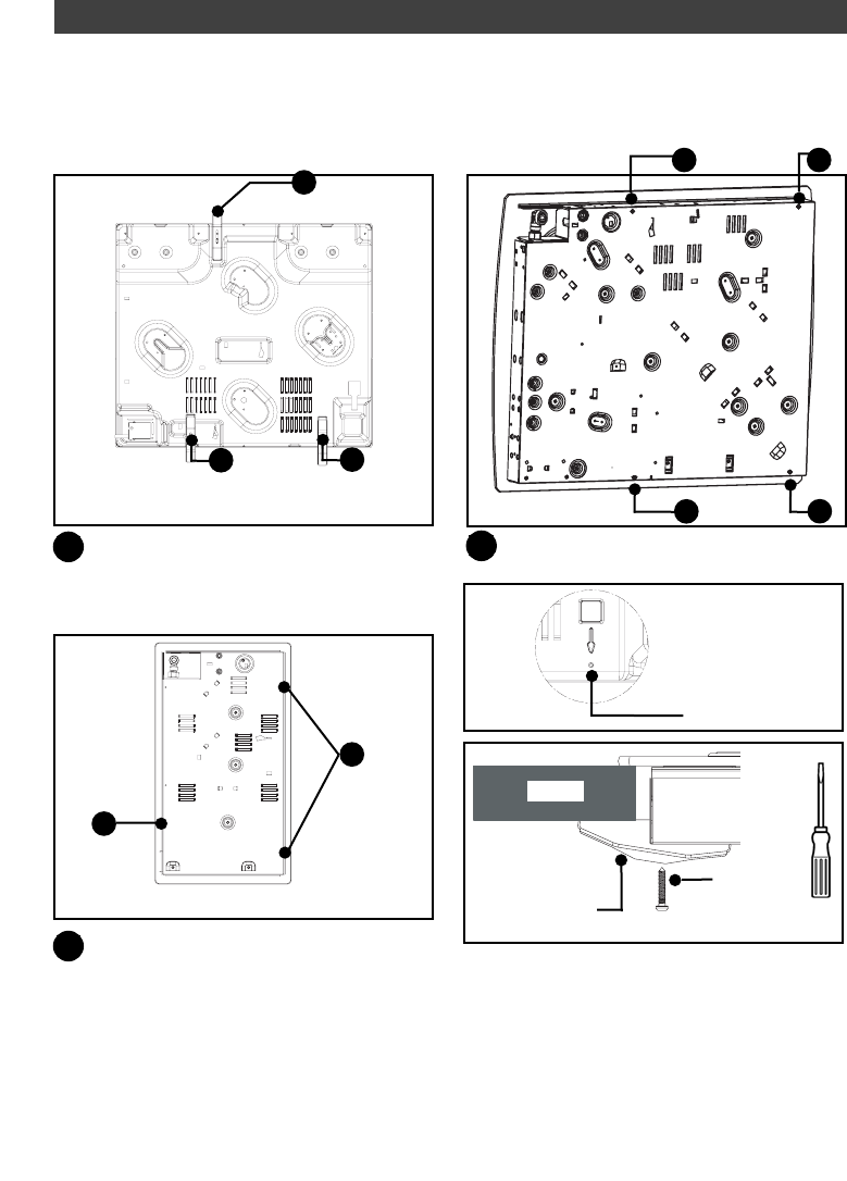
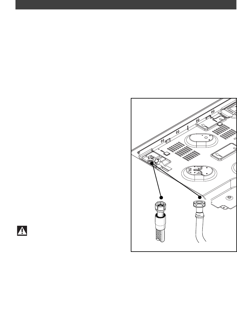
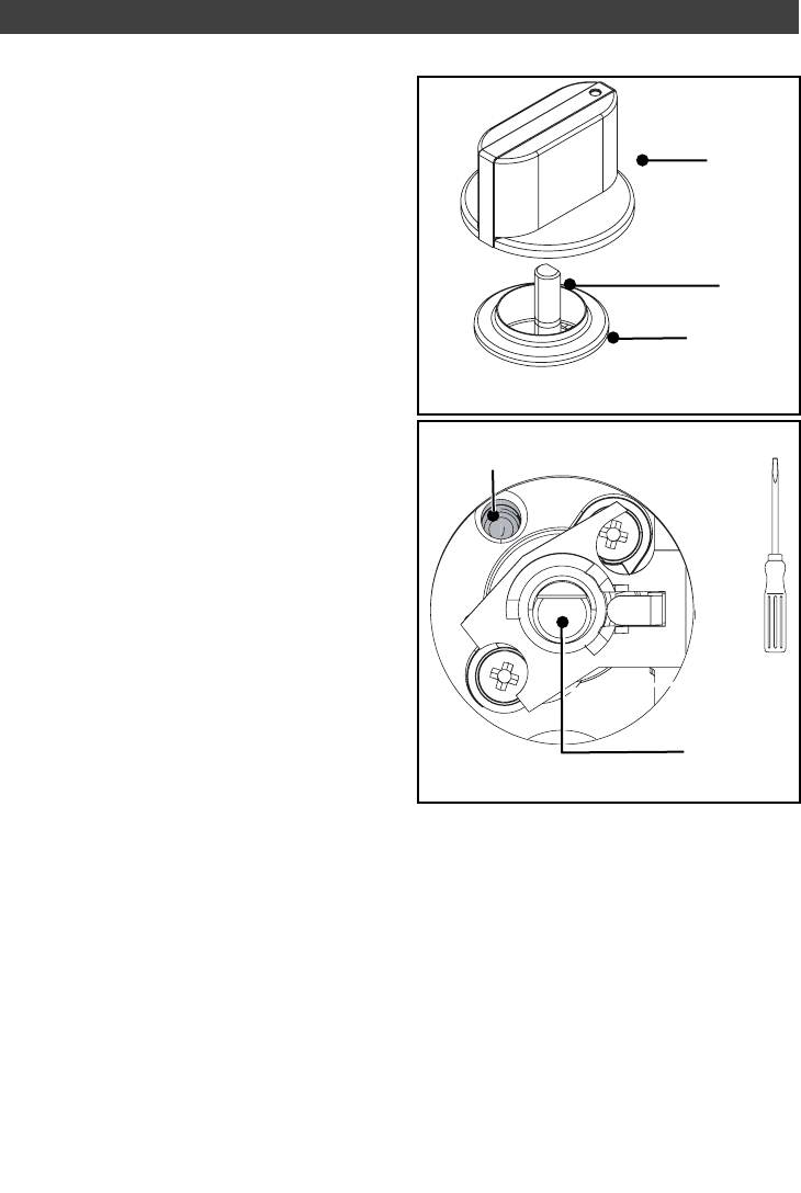
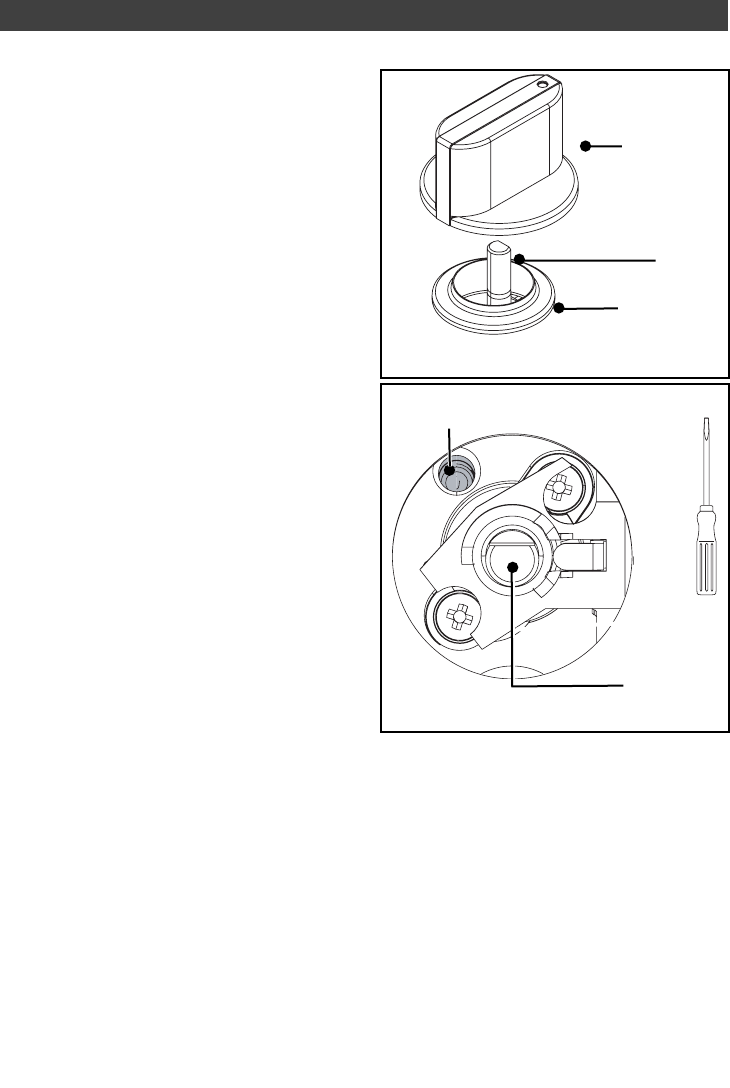
    Ik belde met deze informatie een witgoedmonteur. Die monteur had ófwel niet zoveel zin in de klus, ófwel hij wist niet waar hij het over had. Hij kwam - net als ik - tot de conclusie dat pomp en motor goed functioneren. Maar hij was tevens van mening dat het de condensator niet kon zijn. Enfin, de monteur die beweerde verder geen idee te hebben maakte absoluut geen aanstalte om langs te komen. Wellicht kwam dit ook omdat hij de Fagor vaatwasser té goed kende. Hij wist nog wel aan te geven dat Fagor in 2013 failliet ging. Informatie waar je verder niet zoveel aan hebt. Onderdelen zoals een condensator en de pomp zijn universeel verkrijgbaar. Hier heb je Fagor niet voor nodig. Maar de condensator bij de Fagor ES38IT zit wel erg diep verstopt. Ik vermoed nog steeds dat de monteur dit wist en gewoon geen zin had in een té lastige klus. Spoiler allert: het is mij niet gelukt om de condensator te verwijderen. Ik kon hem net met een vingertop aanraken. Maar geen zorg: je hoeft hem ook niet persé te verwijderen. Want met een punttang kun je de kabelschoentjes van de condensator lostrekken. De defecte condensator kun je gewoon laten zitten waar hij zit. Want je hebt dan nog voldoende ruimte en kabellengte om de nieuwe condensator aan te sluiten en te plaatsen. Die condensator plaats je met wat creativiteit (en een beugeltje uit je klussendoos) terug in de machine. Juist voor de motor (tussen de motor en de zijwand in) is net voldoende ruimte hiervoor. Voor een eventuele toekomstige storing zit hij dan direct op een beter plek. De condensator bevindt zich aan de linkerzijde van de machine, onderin achter. Je moet even de zijplaat verwijderen (en de isolatiemat die hier los overheen hangt). Dat metalen zijpaneel zit vast met 2 of 3 schroefjes (torx), de achterzijde moet je even over een hobbeltje heen openbuigen. Onderin de zijkant ontstaat dan een opening waarin je als je naar binnen kijkt direct de motor ziet, maar daarop gemonteerd de condensator. Ik heb me laten vertellen dat de meeste vaatwassers 2 condensatoren bevatten. Ik heb er echter maar één kunnen vinden.

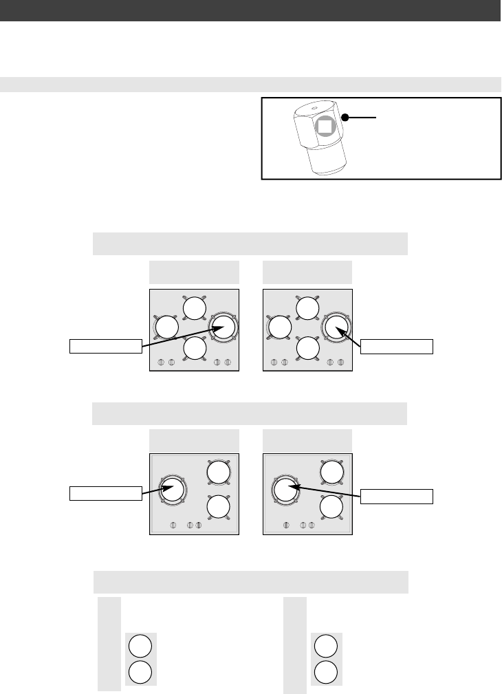
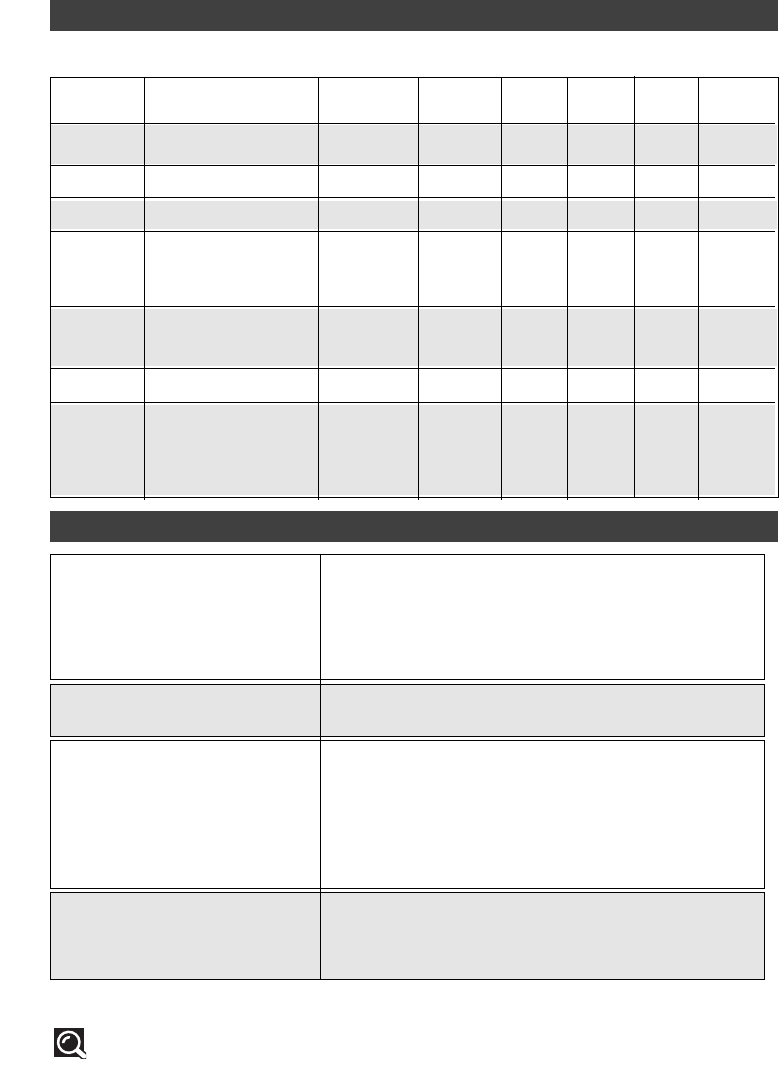
    In de beperkte ruimte kon ik zien dat er een Ducati Energia 416.433.580 condensator op de motor in de machine zat met een capaciteit van 2,5 µF (aluminium behuizing). Die capaciteit is bepalend. Bij PartsNL bestelde ik een Universeel Condensator 2,5 µF 4016417048654 032002UN voor EUR 4,49 en ontving een 4-polige CBB60 condensator met kunststof behuizing. Even schrikken: in de machine zat een condensator met 2 polen en ik ontving er één met 4 polen. Iene, miene, mutte . . . iets overhaast bestelde ik zelfs bij Kabelshop.nl al een tweede (Aanloop) condensator 2.5 µF (Max. 450V, Fixapart K010809003) die 2 polen zou moeten hebben. Prijs EUR 1,95. Die tweede condesnator heb ik echter niet nodig gehad (op dit moment moet ik hem zelfs nog ontvangen). Ik zal hem na ontvangst bewaren voor een eventuele toekomstige storing.

    Want inmiddels vond ik op internet de volgende aanvullende informatie:
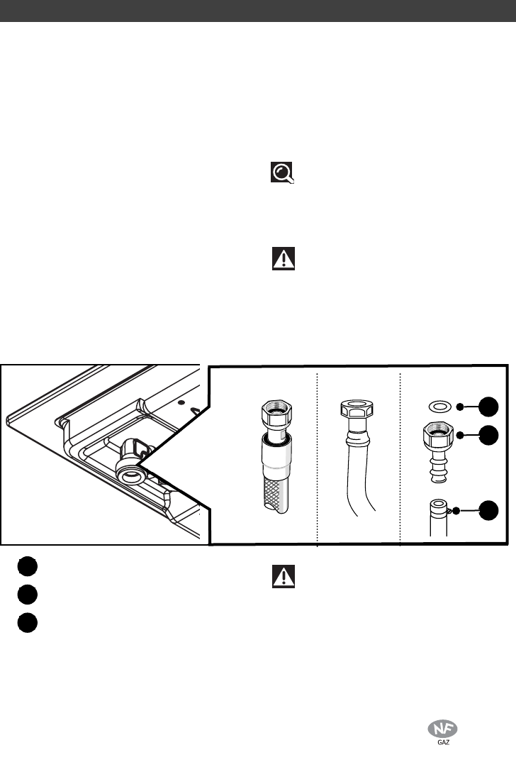
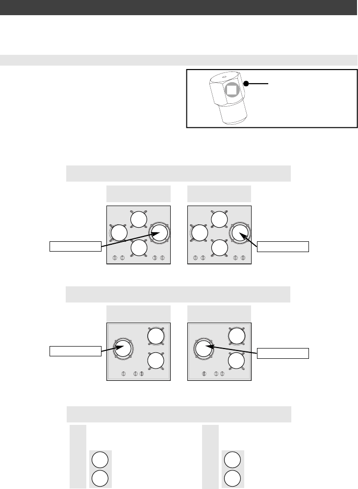
    - De twee boven elkaar liggende aansluitingen staan met elkaar in verbinding. Dus links is 2x pin 1, rechts is 2x pin 2. Dit leek zelfs bevestigd te worden (toeval of niet) door de behuizing zelf. Tussen de boven elkaar liggende aansluitingen lijkt een "bruggetje" in de behuizing zichtbaar.
    - Dit soort condensatoren zouden niet polariteitsgevoelig zijn (bi-polair), ze hebben GEEN + of -, gewoon aansluiten dus. Dit leek bevestigd te worden door de condensator zelf (en verpakking) er wordt nergens een indicatie gegeven voor + of -.
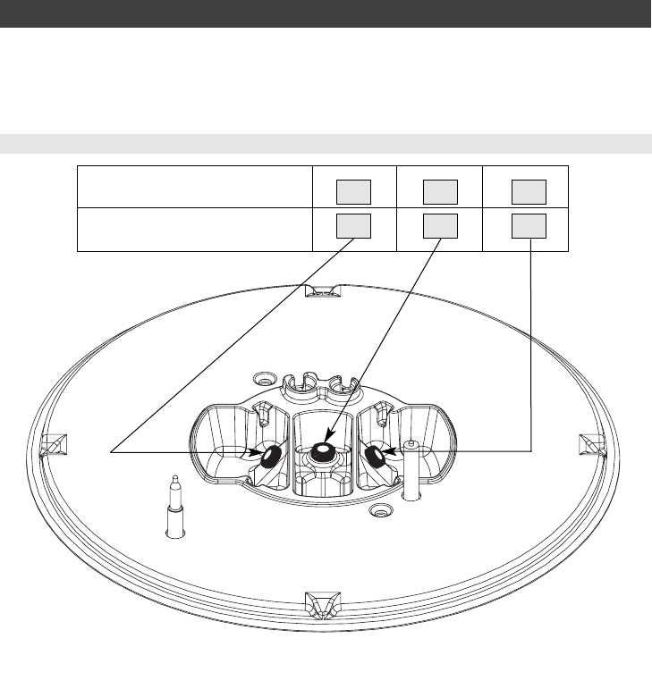
    - Een aanloopcondensator heeft een lagere werkspanning (250-350 Volt). Staat op de defecte condensator bv. 250 of 350 Volt, dan kan zonder probleem een van 400-450 Volt worden geplaatst. Staat op de defecte condensator bv. 400 of 450 Volt, dan NOOIT een condensator met een lagere spanning plaatsen. Oftewel: gewoon altijd een 400-450 Volt plaatsen.

    Ik heb (wanneer je de tekst met specificaties op de condensator zichtbaar - dus omhoog - plaatst) de 2 onderste polen afgeplakt met tape (geisoleerd). De 2 bovenste polen heb ik (willekeurig) aangesloten.

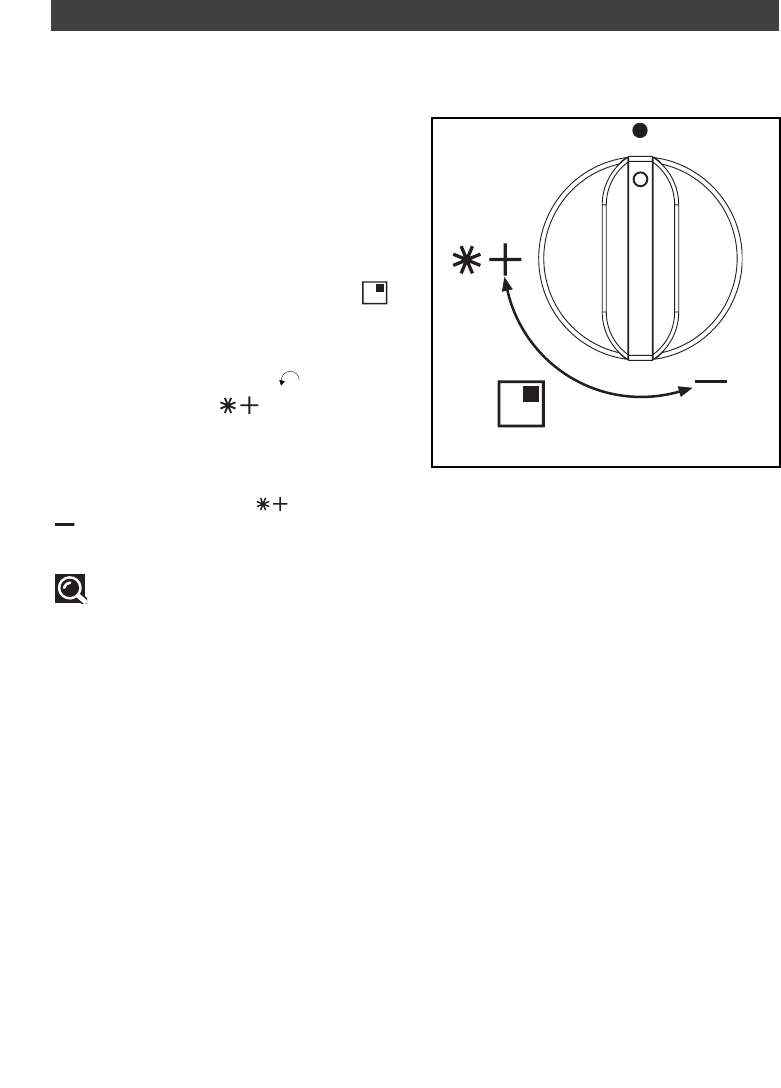
    Daarna heb ik de machine getest: een wasprogramma van 30 minuten verliep zonder problemen. Direct daarna een wasprogramma van 60 minuten verliep zonder problemen. Toen heb ik de vaatwasser weer ingebouwd.
    Gesteld op 10-11-2020 om 06:50

    Reageer op deze vraag Misbruik melden

Misbruik melden

Gebruikershandleiding.com neemt misbruik van zijn services uitermate serieus. U kunt hieronder aangeven waarom deze vraag ongepast is. Wij controleren de vraag en zonodig wordt deze verwijderd.

Product:

Bijvoorbeeld antisemitische inhoud, racistische inhoud, of materiaal dat gewelddadige fysieke handelingen tot gevolg kan hebben.

Bijvoorbeeld een creditcardnummer, een persoonlijk identificatienummer, of een geheim adres. E-mailadressen en volledige namen worden niet als privégegevens beschouwd.

Spelregels forum

Om tot zinvolle vragen te komen hanteren wij de volgende spelregels:

Belangrijk! Als er een antwoord wordt gegeven op uw vraag, dan is het voor de gever van het antwoord nuttig om te weten als u er wel (of niet) mee geholpen bent! Wij vragen u dus ook te reageren op een antwoord.

Belangrijk! Antwoorden worden ook per e-mail naar abonnees gestuurd. Laat uw emailadres achter op deze site, zodat u op de hoogte blijft. U krijgt dan ook andere vragen en antwoorden te zien.

Abonneren

Abonneer u voor het ontvangen van emails voor uw Fagor ES 38 IT bij:


U ontvangt een email met instructies om u voor één of beide opties in te schrijven.


Ontvang uw handleiding per email

Vul uw emailadres in en ontvang de handleiding van Fagor ES 38 IT in de taal/talen: Nederlands, Duits, Engels, Frans, Portugees, Spaans, Spaans als bijlage per email.

De handleiding is 3,35 mb groot.


U ontvangt de handleiding per email binnen enkele minuten. Als u geen email heeft ontvangen, dan heeft u waarschijnlijk een verkeerd emailadres ingevuld of is uw mailbox te vol. Daarnaast kan het zijn dat uw internetprovider een maximum heeft aan de grootte per email. Omdat hier een handleiding wordt meegestuurd, kan het voorkomen dat de email groter is dan toegestaan bij uw provider.

Stel vragen via chat aan uw handleiding

Stel uw vraag over deze PDF

Uw handleiding is per email verstuurd. Controleer uw email

Als u niet binnen een kwartier uw email met handleiding ontvangen heeft, kan het zijn dat u een verkeerd emailadres heeft ingevuld of dat uw emailprovider een maximum grootte per email heeft ingesteld die kleiner is dan de grootte van de handleiding.

Er is een email naar u verstuurd om uw inschrijving definitief te maken.

Controleer uw email en volg de aanwijzingen op om uw inschrijving definitief te maken

U heeft geen emailadres opgegeven

Als u de handleiding per email wilt ontvangen, vul dan een geldig emailadres in.

Uw vraag is op deze pagina toegevoegd

Wilt u een email ontvangen bij een antwoord en/of nieuwe vragen? Vul dan hier uw emailadres in.


Info