ENGLISH ............................................................................................................................................................................................................4
PREPARATIONS FOR MAINTENANCE ..................................................................................................................................................................................................7
COMbuSTION AIR ......................................................................................................................................................................................................................................9
ILary PLuS dEtaILS .....................................................................................................................................................................................11
fLuE GaS outLEt ..........................................................................................................................................................................................12
Hot aIr ductING ..........................................................................................................................................................................................13
AddITIONAl THERMOSTAT TO CONTROl THE duCT MOTOR ...............................................................................................................................................13
coMbuStIoN aIr ..........................................................................................................................................................................................13
oPEratIoN IN aIr ductING WItH tHErMoStat or ProbE (oPtIoNaL) ............................................................................................14
NotES for corrEct oPEratIoN ..............................................................................................................................................................15
PELLEtS aNd LoadING ................................................................................................................................................................................16
radIo coNtroL ............................................................................................................................................................................................18
RAdIO CONTROl dEvICE ROOM PRObE CAlIbRATION ...........................................................................................................................................................18
bATTERY TYPE ANd REPlACEMENT .................................................................................................................................................................................................18
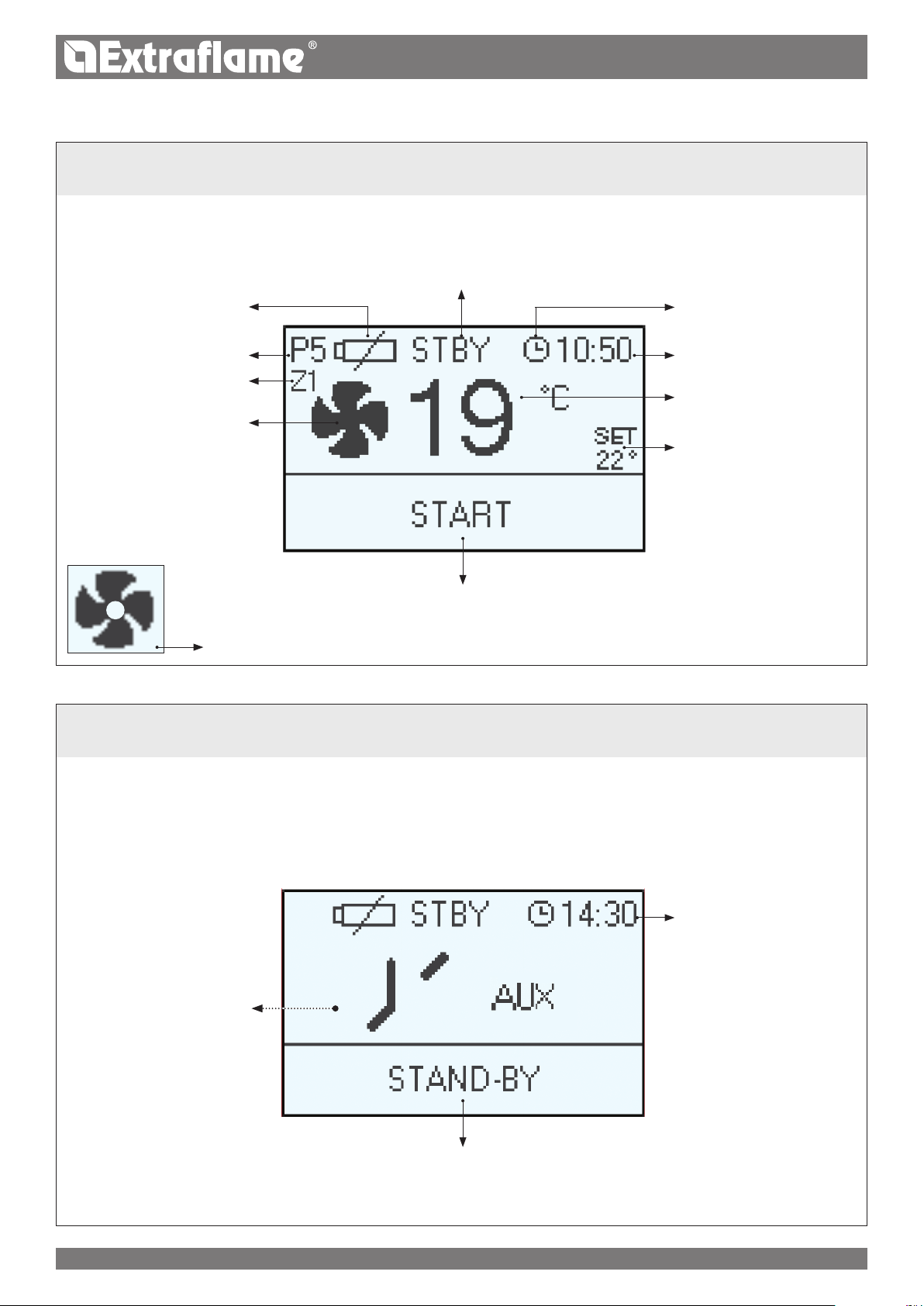
radIo coNtroL dEvIcE fEaturES ...........................................................................................................................................................19
GENEraL MENu .............................................................................................................................................................................................21
GENERAl wARNINGS ..............................................................................................................................................................................................................................21
fIrSt IGNItIoN SEttINGS ............................................................................................................................................................................22
lANGuAGE ..................................................................................................................................................................................................................................................22
oPEratIoN aNd LoGIc ................................................................................................................................................................................23
aIr ductING (ILary PLuS) ..........................................................................................................................................................................24
aIr ZoNE coNtroL (ILary PLuS) ...............................................................................................................................................................25
EXAMPlE ......................................................................................................................................................................................................................................................27
CHRONO TIME SlOT ................................................................................................................................................................................................................................27
AuX ................................................................................................................................................................................................................................................................27
STANd bY .....................................................................................................................................................................................................................................................28
OPERATION wITH AddITIONAl THERMOSTAT (OPTIONAl) .................................................................................................................................................28
FIRST lOAd .................................................................................................................................................................................................................................................29
EASY CONTROl .........................................................................................................................................................................................................................................29
OPERATION ANd SOluTIONS .............................................................................................................................................................................................................30
RAdIO PRObE .............................................................................................................................................................................................................................................30
cLEaNING aNd MaINtENaNcE ...................................................................................................................................................................32
PERIOdIC ClEANING uNdER uSER'S RESPONSIbIlITY .............................................................................................................................................................32
routINE MaINtENaNcE PErforMEd by QuaLIfIEd tEcHNIcIaNS ....................................................................................................34
SHuT-dOwN (ENd OF SEASON) ........................................................................................................................................................................................................34
During combustion, thermal energy is released that signicantly increases the heat of surfaces, doors, handles, controls, glass, exhaust
pipes, and even the front of the appliance. Avoid contact with those elements if not wearing protective clothing (protective gloves
included). Make sure children are aware of the danger and keep them away from the stove during operation.
4ENGLISH
Warnings
This instructions manual is an integral part of the product: make sure that
it always accompanies the appliance, even if transferred to another owner
or user, or if transferred to another place. If it is damaged or lost, request
another copy from the area technician. This product is intended for the use
for which it has been expressly designed. The manufacturer is exempt from
any liability, contractual and extracontractual, for injury/damage caused to
persons/animals and objects, due to installation, adjustment and mainte-
nance errors and improper use.
Installation must be performed by qualied sta, which assumes com-
plete responsibility for the denitive installation and consequent good
functioning of the product installed. One must also bear in mind all laws
and national, regional, provincial and town council Standards present
in the country in which the appliance has been installed, as well as the
instructions contained in this manual.
The use of the appliance must comply with all local, regional, national
and European regulations.
The Manufacturer cannot be held responsible for the failure to comply
with such precautions.
After removing the packaging, ensure that the content is intact and com-
plete. Otherwise, contact the dealer where the appliance was purchased.
All electric components that make up the product must be replaced with
original spare parts exclusively by an authorised after-sales centre, thus
guaranteeing correct functioning.
safety
THE APPLIANCE MAY BE USED BY CHILDREN 8 YEARS OF AGE OR
OLDER AND INDIVIDUALS WITH REDUCED PHYSICAL, SENSORY, OR
MENTAL CAPACITIES OR WITHOUT EXPERIENCE OR THE NECESSARY
KNOWLEDGE, PROVIDED THAT THEY ARE SUPERVISED OR HAVE
We thank you for having chosen our company; our product is a great heating solution developed from the
most advanced technology with top quality machining and modern design, aimed at making you enjoy the
fantastic sensation that the heat of a ame gives, in complete safety.
5ENGLISH
RECEIVED INSTRUCTIONS ON SAFE USE OF THE APPLIANCE AND THAT
THEY UNDERSTAND THE INHERENT DANGERS.
THE GENERATOR MUST NOT BE USED BY PERSONS INCLUDING
CHILDREN WITH REDUCED PHYSICAL, SENSORY AND MENTAL
CAPACITIES OR WHO ARE UNSKILLED PERSONS, UNLESS THEY ARE
SUPERVISED AND TRAINED REGARDING USE OF THE APPLIANCE BY A
PERSON RESPONSIBLE FOR THEIR SAFETY.
THE CLEANING AND MAINTENANCE REQUIRED BY THE USER MUST
NOT BE PERFORMED BY CHILDREN WITHOUT SUPERVISION.
CHILDREN MUST BE CHECKED TO ENSURE THAT THEY DO NOT PLAY
WITH THE APPLIANCE.
DO NOT TOUCH THE GENERATOR WHEN YOU ARE BAREFOOT OR
WHEN PARTS OF THE BODY ARE WET OR DAMP.
IT IS FORBIDDEN TO MODIFY THE APPLIANCE IN ANY WAY.
DO NOT PULL, REMOVE, TWIST THE ELECTRICAL CABLES COMING
OUT OF THE PRODUCT EVEN IF IT IS DISCONNECTED FROM THE MAINS.
IT IS ADVISED TO POSITION THE POWER SUPPLY CABLE SO THAT IT
DOES NOT COME INTO CONTACT WITH HOT PARTS OF THE APPLIANCE.
THE POWER SUPPLY PLUG MUST BE ACCESSIBLE AFTER
INSTALLATION.
DO NOT CLOSE OR REDUCE THE DIMENSIONS OF THE AIRING VENTS
IN THE PLACE OF INSTALLATION. THE AIRING VENTS ARE ESSENTIAL
FOR CORRECT COMBUSTION.
DO NOT LEAVE THE PACKAGING ELEMENTS WITHIN REACH OF
CHILDREN OR UNASSISTED DISABLED PERSONS.
THE HEARTH DOOR MUST ALWAYS BE CLOSED DURING NORMAL
FUNCTIONING OF THE PRODUCT.
WHEN THE APPLIANCE IS FUNCTIONING AND HOT TO THE TOUCH,
ESPECIALLY ALL EXTERNAL SURFACES, ATTENTION MUST BE PAID
CHECK FOR THE PRESENCE OF ANY OBSTRUCTIONS BEFORE
SWITCHING THE APPLIANCE ON FOLLOWING A PROLONGED PERIOD
OF INACTIVITY.
THE GENERATOR HAS BEEN DESIGNED TO ADJUST ITSELF
AUTOMATICALLY IN PARTICULAR OPERATING CONDITIONS
THE GENERATOR HAS BEEN DESIGNED TO FUNCTION IN ANY
CLIMATIC CONDITION. IN PARTICULARLY ADVERSE CONDITIONS
6ENGLISH
STRONG WIND, FREEZING SAFETY SYSTEMS MAY INTERVENE
THAT SWITCH THE GENERATOR OFF. IF THIS OCCURS, CONTACT THE
TECHNICAL AFTERSALES SERVICE AND ALWAYS DISABLE THE SAFETY
SYSTEMS.
IN THE EVENT THE FLUE CATCHES FIRE, USE SUITABLE SYSTEMS
FOR SUFFOCATING THE FLAMES OR REQUEST HELP FROM THE FIRE
BRIGADE.
THIS APPLIANCE MUST NOT BE USED TO BURN WASTE
DO NOT USE ANY FLAMMABLE LIQUIDS FOR IGNITION
DURING THE FILLING PHASE DO NOT PUT THE BAG OF PELLETS TO
INTO CONTACT WITH THE PRODUCT
THE MAJOLICAS ARE TOP QUALITY ARTISAN PRODUCTS AND
AS SUCH CAN HAVE MICRODOTS, CRACKLES AND CHROMATIC
IMPERFECTIONS. THESE FEATURES HIGHLIGHT THEIR VALUABLE
NATURE. DUE TO THEIR DIFFERENT DILATION COEFFICIENT, THEY
PRODUCE CRACKLING, WHICH DEMONSTRATE THEIR EFFECTIVE
AUTHENTICITY. TO CLEAN THE MAJOLICAS, IT IS RECOMMENDED TO
USE A SOFT, DRY CLOTH. IF A DETERGENT OR LIQUID IS USED, THE
LATTER COULD PENETRATE INSIDE THE CRACKLES, HIGHLIGHTING
THEM.
SINCE THE PRODUCT CAN TURN ON AUTOMATICALLY THANKS TO
THE TIMER, OR REMOTELY USING THE DEDICATED APPLICATIONS, IT IS
STRICTLY FORBIDDEN TO LEAVE ANY COMBUSTIBLE OBJECT WITHIN
THE SAFETY DISTANCES INDICATED ON THE TECHNICAL DATA PLATE.
INTERNAL COMBUSTION CHAMBER PARTS CAN BE SUBJECT TO
EXTETICAL WARN, IT DOESN'T AFFECT THE FUNCTIONALITY
routine Maintenance
Based on Decree 22 January 2008 n°37 art.2, routine maintenance means
interventions aimed at reducing degradation due to normal use, as well
as dealing with accidental events entailing the need of rst interventions,
which however do not modify the structure of the system upon which one
is intervening or its intended use according to the requirements laid down
by the technical standards in force and by the manufacturer's use and main-
tenance manual.
7ENGLISH
INSTALLING INSERTS
When installing inserts, access must be prevented to the internal parts of the appliance and it must not be possible to access live parts during
extraction operations.
Any wiring, for example the power cable or room probe, must be positioned so as not to be damaged during movement of the insert and must
not come into contact with hot parts. If a cavity made of combustible material is installed, we recommend taking all the safety precautions
indicated by the installation standards.
VENTILATION AND AERATION OF INSTALLATION ROOMS
In case of non-airtight heater and/or installation, the ventilation must respect the minimum area indicated below (considering the highest value
among those provided):
Appliance categoriesReference standard
Percentage of the
net opening section with respect to the
appliance fumes outlet section
Minimum net opening value of the
ventilation duct
Pellet stovesUNI EN 14785-80 cm²
BoilersUNI EN 303-550%100 cm²
INSTALLATION
GENERAL
The ue gas exhaust and hydraulic connections must be carried out by qualied personnel who must issue installation conformity
documentation compliant with national standards.
The installer must provide the owner or person acting for him, according to the legislation in force, with the declaration of conformity,
supplied with:
1) the use and maintenance manual of the appliance and of the system components (such as for example, the smoke ducts, chimney, etc.);
2) photocopy or photograph of the chimney plaque;
3) system booklet (where applicable).
The installer must ask to be issued with a receipt stating that the documentation has been provided, and must keep it with a copy of the technical
documentation relating to the installation.
For installation in a condominium, prior approval from the condominium's administrator must be requested.
Where required, check the exhaust gas emissions after installation. Should a sampling point be installed, it must be airtight.
COMPATIBILITY
Do not install in rooms with a re hazard. It is also forbidden to install it in living areas with the following characteristics:
1. where there are liquid fuel appliances with continuous or discontinuous operation that draw the combustion air into the room in which they
are installed.
2. where there are type B gas appliances intended for heating, with or without domestic hot water production and in adjacent and communicating
rooms.
3. where the depression measured in situ between the external and internal environment is greater than 4 Pa.
N.B.: Watertight appliances can also be installed in the cases indicated in points 1, 2 and 3 of this paragraph.
INSTALLATIONS IN BATHROOMS, BEDROOMS AND STUDIO FLATS
Installation in bathrooms, bedrooms and studio ats is only allowed for sealed or closed hearth appliances with ducted combustion air taken
from the outside.
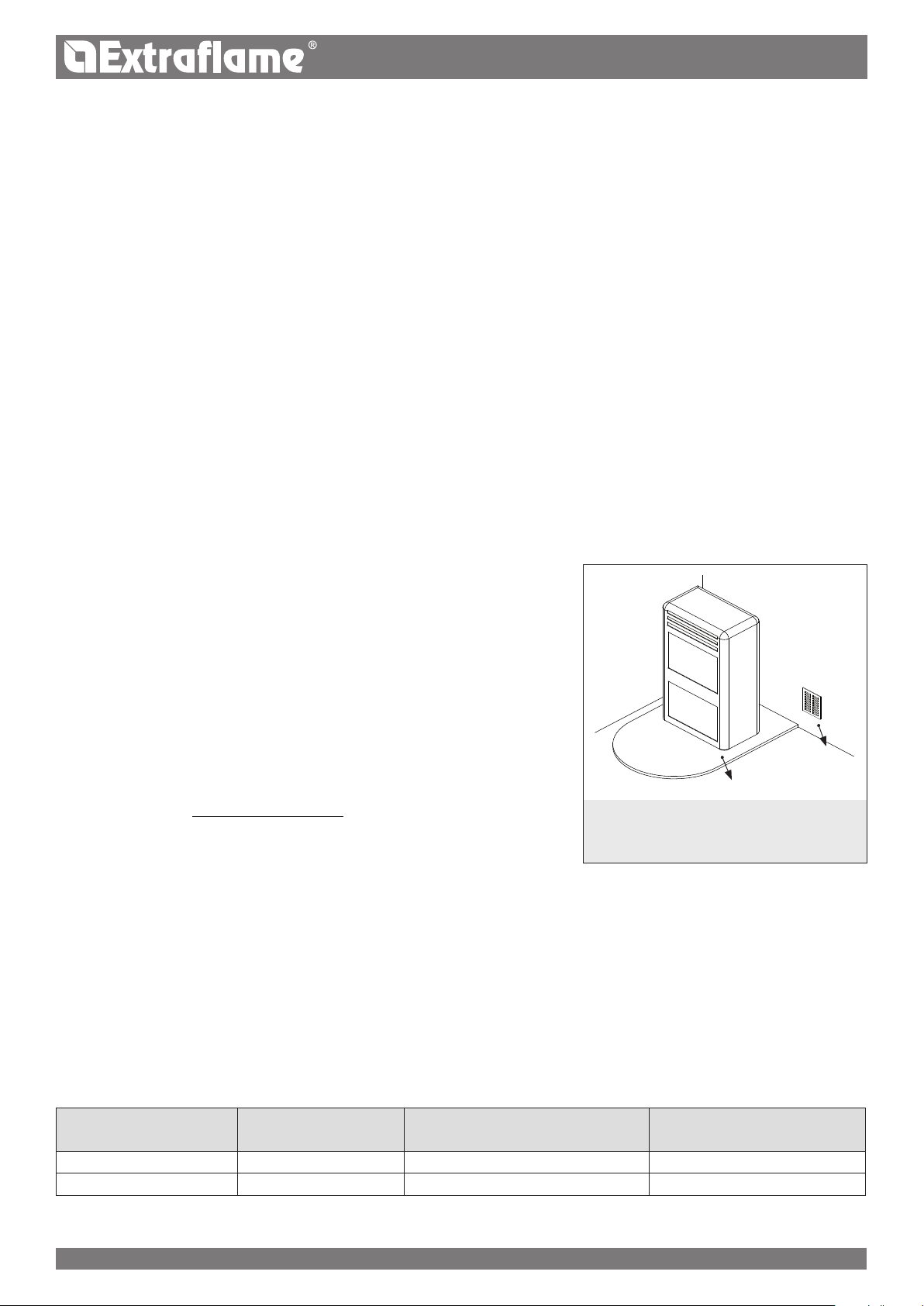
oor protection
POSITIONING AND SAFETY DISTANCES
The support surfaces and/or points must have a suitable capacity to bear the overall weight
of the appliance, accessories and coverings. If the oor is made of a combustible material,
we recommend using a non-combustible material to protect the front part from any burnt
material which might fall during routine cleaning operations. The generator must be level
to function properly. The side walls, the rear walls and the oor support surface should be
made of non-combustible material.
One must also bear in mind all laws and national,
regional, provincial and town council regulations in force
in the country in which the appliance has been installed,
as well as the instructions contained in this manual.
Air inlet
Under any condition, including in the presence of extractor hoods and/or of controlled forced ventilation systems, the pressure dierence
between the generator installation rooms and the outside must always be equal to or less than 4 Pa.
MINIMUM DISTANCES PELLET STOVES
Installation next to ammable or heat-sensitive materials is permitted only if the special
safety distances specied on the label at the beginning of the manual (pag.2) are
observed. If the materials are not ammable, you must keep a side and rear distance of at
least 100 mm (without the inserts). For products equipped with rear spacers, wall-mounting
installation is permitted exclusively for the rear side.
PREPARATIONS FOR MAINTENANCE
To carry out extraordinary maintenance operations on the product, it may be necessary to move it away from the adjacent walls. This must be
done by a technician authorised to disconnect the combustion product evacuation ducts and then reconnect them. For heaters connected to the
hydraulic system, the connection between the system itself and the product must be made in such a way that, when an authorised technician is
about to carry out extraordinary maintenance operations, it is possible to move the heater at least 1 metre away from the adjacent walls.
3 - 5%
Max 3 mt
8ENGLISH
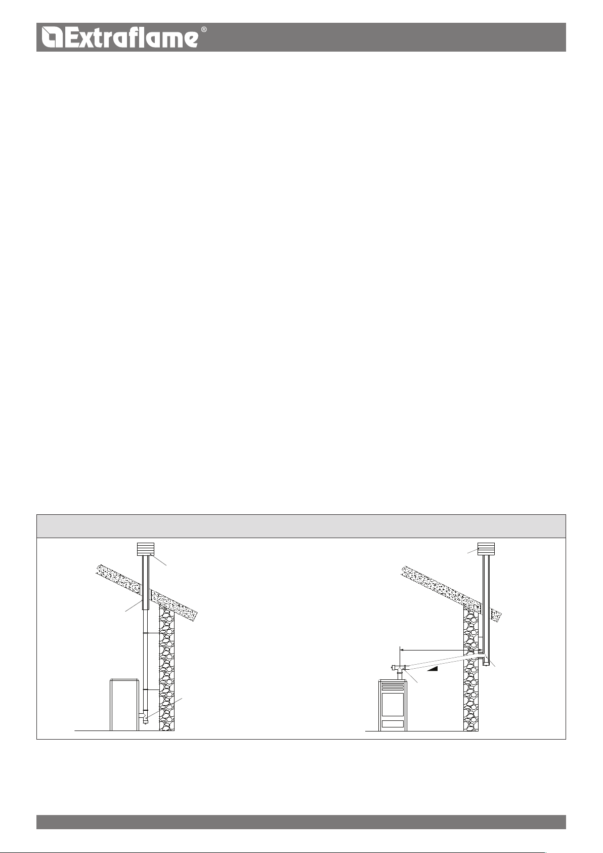
EXAMPLES OF CORRECT CONNECTION TO THE CHIMNEY
In the presence of type B gas appliances with intermittent operation not intended for heating, they must have their own aeration and/or
ventilation opening.
The air inlets must meet the following requirements:
they must be protected with grids, metal mesh, etc., but without reducing the net useful section;
they must be made so as to make the maintenance operations possible;
positioned so that they cannot be obstructed;
The clean and non-contaminated air ow can also be obtained from a room adjacent to that of installation (indirect aeration and
ventilation), as long as the ow takes place freely through permanent openings communicating with the outside.
The adjacent room cannot be used as a garage, or to store combustible material or for any other activity with a re hazard, bathroom,
bedroom or common room of the building.
FLUE GAS EXHAUST
The heat generator works in depression and is equipped with an outlet fan for ue gas extraction. There must be a single exhaust system for
the generator. Using a ue that is shared with other devices is not allowed.
The components of the ue gas exhaust system must be chosen in relation to the type of appliance to be installed in compliance with:
UNI/ TS 11278 in the event of metal chimneys, with particular attention to that stated in the specication;
UNI EN 13063-1 and UNI EN 13063-2, UNI EN 1457, UNI EN 1806 in the event of non-metallic chimneys.
The length of the horizontal section must be minimal and, in any case, no longer than 3 metres, with a minimum upward slope of 3%
There must not be more than 4 direction changes including the one due to the use of the "T" element.
A “T” tting with a condensation collection cap must be provided at the base of the vertical section.
If the exhaust is not inserted in an existing ue, a vertical section with a windproof end piece is required (UNI 10683).
The vertical duct can be inside or outside the building. If the smoke duct is inserted in an existing ue, it must be certied for solid fuel.
If the smoke duct is outside the building, it must always be insulated.
The smoke ducts must have at least one airtight inlet for ue gas sampling.
All the sections of the ue gas duct must be accessible to inspection.
Inspection openings must be provided for cleaning.
If the generator has a fume temperature lower than 160°C+ ambient temperature caused by the high yield (contact technicians) it
MUST be resistant to humidity.
A ue system that does not respect the previous points or, in general, that does not comply with the regulations, may cause condensation
phenomena inside it.
CHIMNEY CAP
The chimney caps must meet the following requirements:
they must have a useful outlet section no less than double that of the chimney/ducted system on which it is installed;
they must be adapted in order to prevent the penetration of rain and snow in the chimney/ducted system;
they must be built so that, in the event of winds coming from all directions and from any angle, the expulsion of combustion products
is in any case ensured;
Protection from rain
and wind
Condensation-proof
"T" tting with
inspection plug
Insulated ue
Insulated "T"
tting with
inspection plug
Protection from rain and wind
"T" tting with
inspection
plug
CONNECTION TO THE MAINS ELECTRIC SUPPLY
The generator is supplied with an electric power cable to be plugged into a 230V 50 Hz socket, possibly with a circuit breaker switch. The
socket must be easily accessible.
The electrical system must be compliant with standards. The eciency of the earthing circuit must be checked. Unsuitable earthing of the
system can cause malfunctioning for which the manufacturer will not be held liable.
Power supply variations beyond 10% can cause faulty operation of the product.
FOR GERMANY ONLY
The product can be connected to a shared ue (multi-connection) provided that the requirements of the regional and national regulations,
amongst which DIN EN 13384-2, DIN V 18160-1, DIN 18896 and of the MFeuV-2007 (Muster-Feuerungsverordnung) are strictly complied with,
and that the local chimney sweep has checked and approved the installation conditions.
Please also remember the following indications, which the end user must comply with:
•The device can be operated only with the doors closed.
•The doors and all setting devices must remain closed when the device is not on (except for cleaning and maintenance operations).
Max 4 mt
9ENGLISH
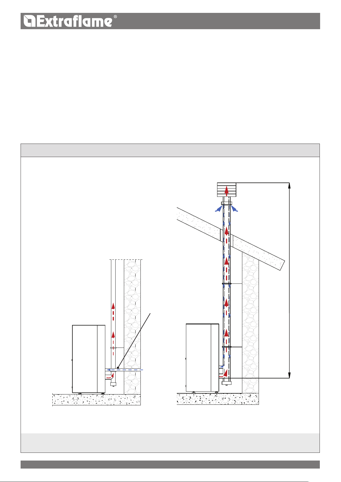
installation example
One must also bear in mind all laws and national, regional, provincial and town council regulations in force in the country in which the appliance has been
installed, as well as the instructions contained in this manual.
Max. 1.5 m -
max. 2 elbows
Hermetically sealed installation
The generator is a fully sealed product with respect to the environment in which it is installed. This means that it is ideal for passive houses
because it does not take air in from within the house.
combustion air
To ensure the stove remains hermetically sealed, the connection pipe for the combustion air must be directly connected to the exterior, using
special pipes and sealed connectors.
Fumes exHaust system
•If the generator has a fumes temperature of less than 160°C+ room temperature due to the high performance (refer to technical data),
the fumes exhaust system must be completely waterproof.
•If there is a possibility that fumes may condense, an external inspection hatch must be tted.
B
D
A
F
G
H
I
E
J
*C
10ENGLISH
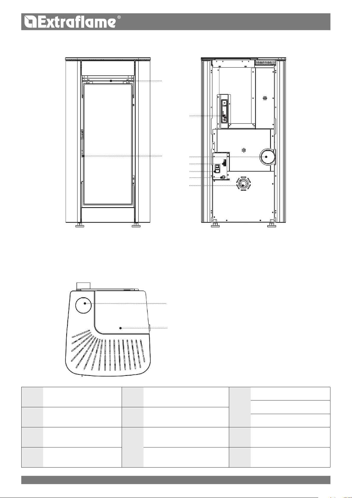
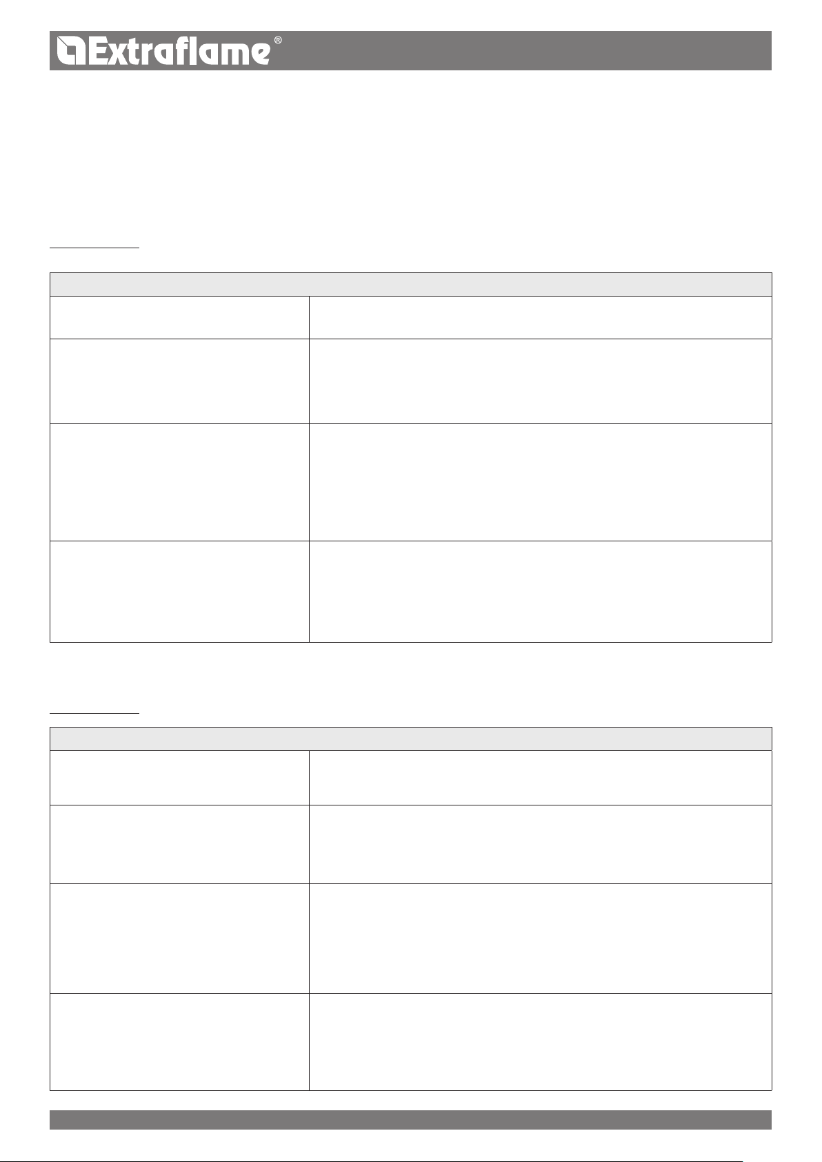
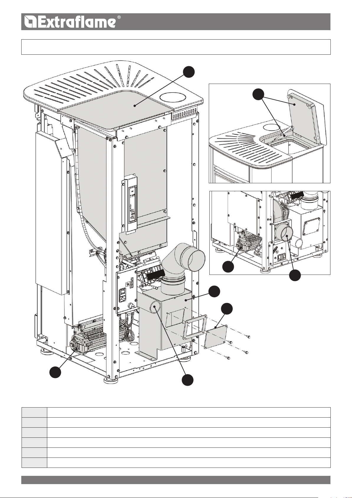
ILARY DEtAILs
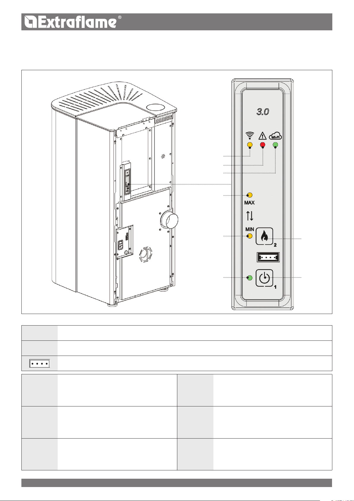
ARoom air outletERadio/emergency board
H
On/O
Fuse
BAccess to combustion chamber
and ash drawerFRear ue gas outlet230 V power supply
*CUpper fumes exhaust
G
Serial inputIResetting
DPellet hopperAdditional thermostat
inputJCombustion air inlet
* NOT VALID FOR FRANCE
B
A
G
H
I
J
E
K
F
D
*C
11ENGLISH
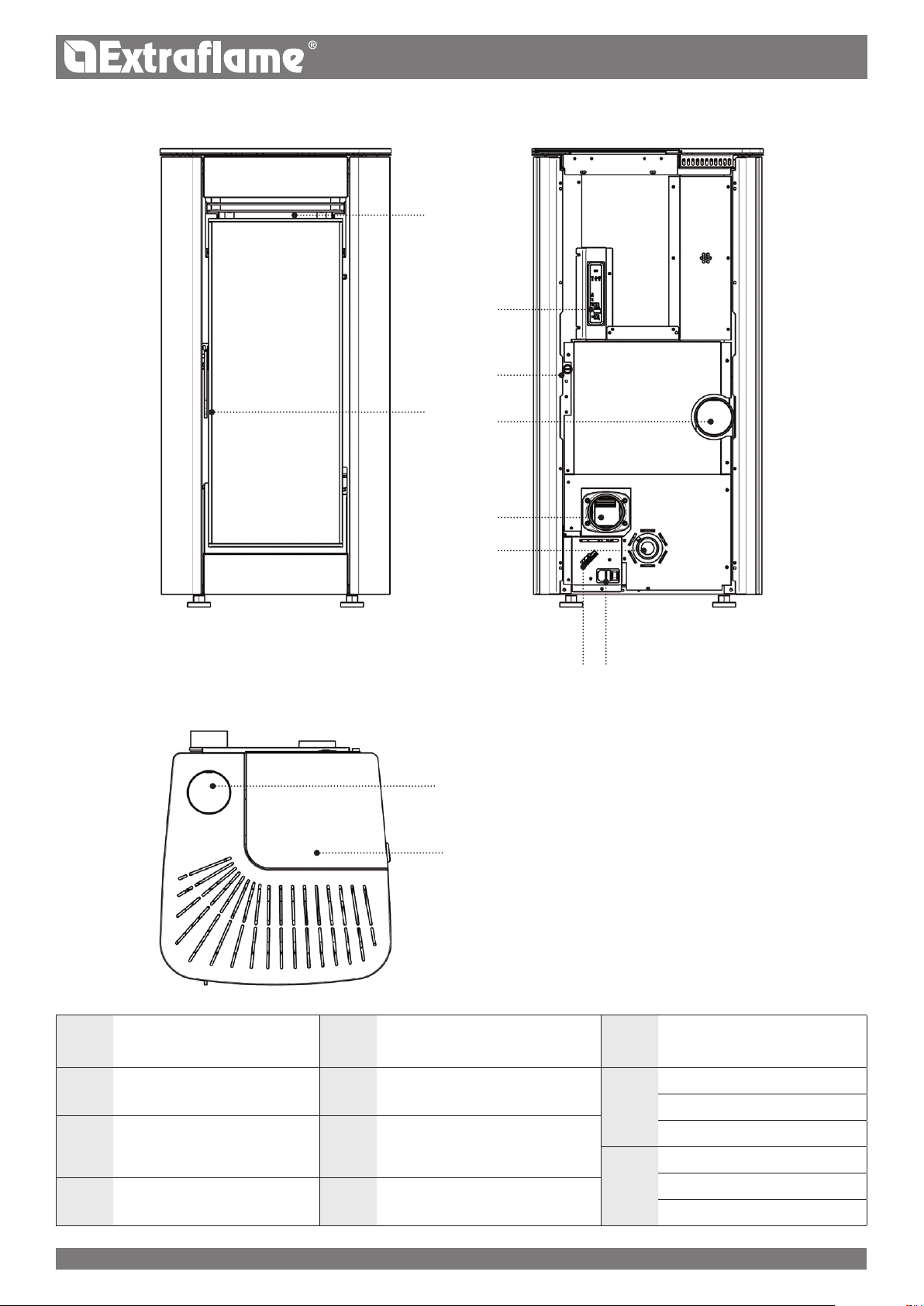
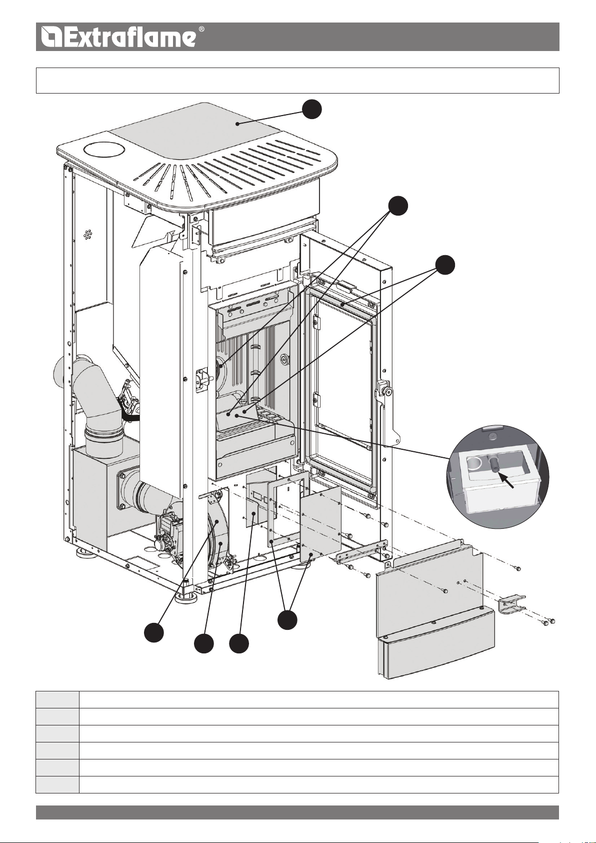
ILARY PLUs DEtAILs
ARoom air outletERadio/emergency boardICombustion air inlet
BAccess to combustion chamber
and ash drawerFResetting
J
Serial input
Additional thermostat input
*CUpper fumes exhaustGRear ue gas outletDucting thermostat input
K
On/O
Fuse
DPellet hopperHAir ducting230 V power supply
* NOT VALID FOR FRANCE
1.2.3.
4.5.6.
*
12ENGLISH
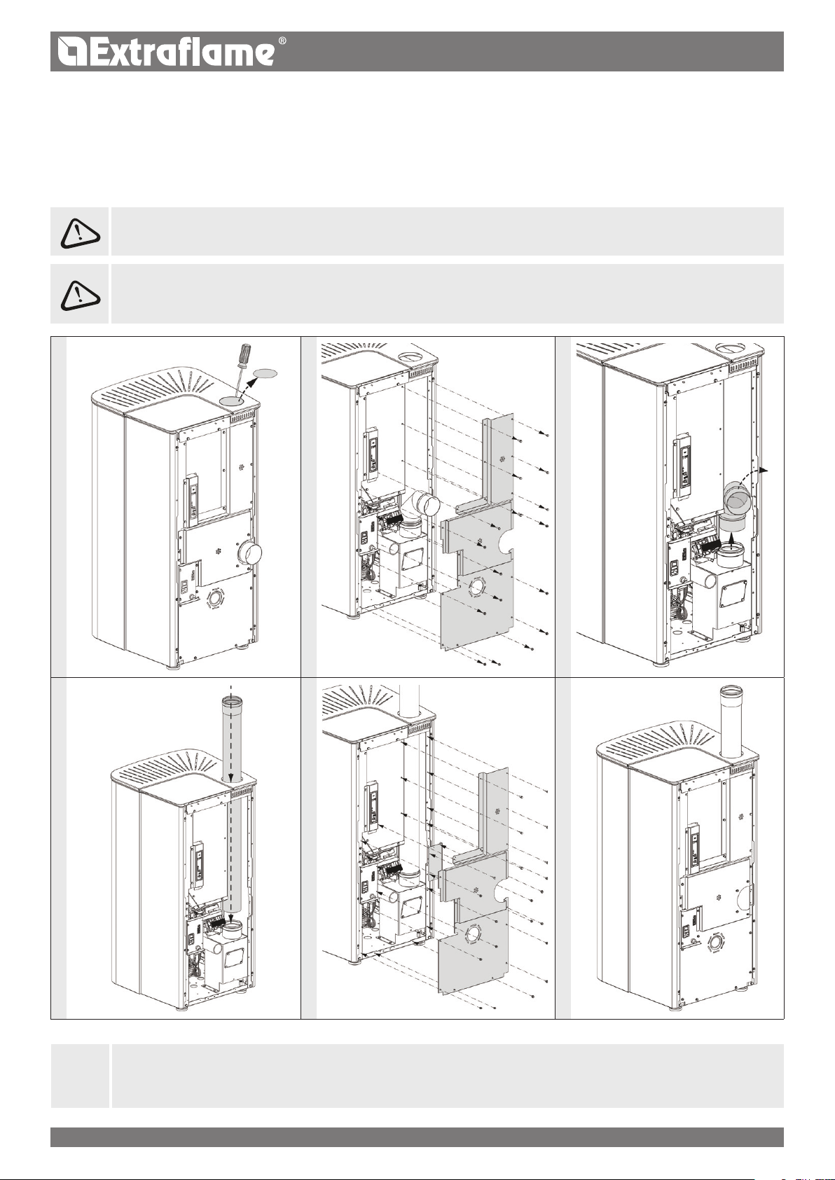
FLUE GAs oUtLEt
By default, the generator is congured to have a rear fumes outlet.
It is possible to move the fumes outlet to the top by following the instructions in the chapter “UPPER FUMES OUTLET ASSEMBLY”
tHE ConvERsIon oF tHE UPPER FLUE GAs oUtLEt MUst BE CARRIED oUt BY QUALIFIED PERsonnEL AnD/oR tHE
MAnUFACtURER’s tECHnICIAns
UPPER FUMEs oUtLEt AssEMBLY
FoLLoW tHE AssEMBLY InstRUCtIons CAREFULLY!
ALWAYs FoLLoW tHE AssEMBLY InstRUCtIons In CoMPLEtE sAFEtY!
tHE stovE MUst BE CoMPLEtELY CoLD, sWItCHED oFF AnD DIsConnECtED FRoM tHE ELECtRICAL PoWER sUPPLY.
*NOT SUPPLIED
J
* IT IS FORBIDDEN TO CARRY OUT THIS ASSEMBLY AND INSTALL THE APPLIANCE WITH THE
UPPER
FLUE GAS OUTLET
FOR ALL USES THROUGHOUT METROPOLITAN FRANCE AND ITS OVERSEAS DEPARTMENTS AND REGIONS DROM,
WHERE REFERENCE IS MADE TO THE REGULATIONS OF THE DTA ISSUED BY THE COMMISSION RESPONSIBLE FOR ISSUING
TECHNICAL ASSESSMENTS CCFAT.
13ENGLISH
CoMBUstIon AIR
The generator has an inlet for drawing combustion air directly from the room or from outside the building.
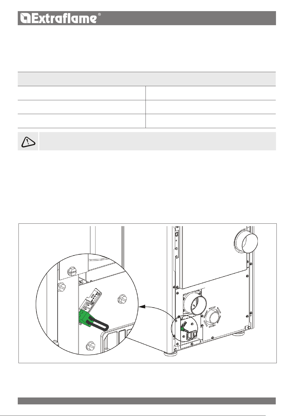
ADDItIonAL tHERMostAt to ContRoL tHE DUCt MotoR
For models with duct motor, it is also possible to thermostat the motor itself. The connection to an external thermostat will allow for the
duct motor to be controlled regardless of stove operation.
At this point, simply set the desired temperature on the thermostat; the thermostat will command the operation of the second motor:
at the set temperature (contact closed), the air ducting motor will follow the stove settings.
when the temperature has been reached (contact open), the motor will switch o.
The duct thermostat terminal features a standard bridge.
See the example image.
Hot AIR DUCtInG
The pipe used for ducting the hot air must have an internal diameter of 80 mm and it must also be insulated or at least be protected against
heat dispersion.
THE RELEVANT HOT AIR DUCTING PIPE MUST BE INSTALLED BY QUALIFIED PERSONNEL AND/OR BY THE MANUFACTURER’S
TECHNICIANS
AIR DUCTING FEATURES
Rear outletPossibility to thermostat the ducting
Diameter of air ducting outlet: 80 mm3 possible settings: OFF, QUIET, REGULAR, BOOST
Maximum recommended air ducting length 8 m
14ENGLISH
WITH PROBE NTC 10K
Remove the jumper and connect the NTC probe in the room that needs to be temperature-controlled through air ducting.
3 control modes:
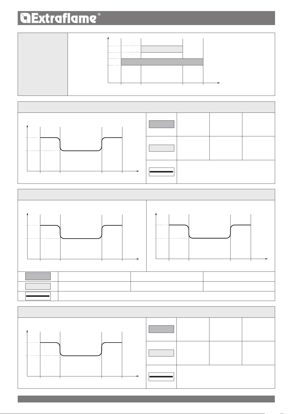
oPERAtIon In AIR DUCtInG WItH tHERMostAt oR PRoBE (oPtIonAL)
The stove is tted with an independent motor for ducting. The connection of an external thermostat or temperature probe (NTC 10K) in the
input, located in the rear part of the stove, makes it possible to control the air ducting motor independently of the stove.
Suce it to connect the thermostat/temperature probe and set the desired temperature.
For information on air ducting settings see chapter:" MENU- AIR DUCTING"
WITH AMBIENT THERMOSTAT OPTIONAL
Remove the jumper and connect the ambient thermostat in the room that needs to be temperature-controlled through air ducting 1.
3 control modes:
OPERATION IN AIR DUCTING WITH AMBIENT THERMOSTAT OPTIONAL
SET congured to OFF
(The temperature setting is not visible)
The air ducting motor will remain o unless the fumes temperature exceeds the normal
operating temperatures
SET on REGULAR
(The temperature setting is not visible)
Once the specic activation threshold has been reached and exceeded, at temperature
to be satised (CLOSED CONTACT) the air ducting motor will follow the stove settings.
When the temperature set on the thermostat is reached (OPEN CONTACT), the air ducting
motor will switch OFF and switch on again when there is a new request.
SET on QUIET
(The temperature setting is not visible)
Once the specic activation threshold has been reached and exceeded, at temperature
to be satised (CLOSED CONTACT) the air ducting motor will follow the stove settings
but at a lower speed than in REGULAR, for greater acoustic-environmental comfort.
When the temperature set on the thermostat is reached (OPEN CONTACT), the ducting
motor will switch o and switch on again when there is a new request.
SET on BOOST
(The temperature setting is not visible)
Once the specic activation threshold has been reached and exceeded, at temperature
to be satised (CLOSED CONTACT) the air ducting motor will follow the stove settings
but at a higher speed than in REGULAR, for faster heat exchange.
When the temperature set on the thermostat is reached (OPEN CONTACT), the ducting
motor will switch o and switch on again when there is a new request.
OPERATION IN AIR DUCTING WITH NTC PROBE 10K OPTIONAL
SET on OFF
Set the desired temperature ( from 7 to 37 °C)
The air ducting motor will remain o unless the fumes temperature exceeds the normal
operating temperatures
SET on REGULAR
Set the desired temperature ( from 7 to 37 °C)
Once the specic activation threshold has been reached and exceeded, at temperature
to be satised the air ducting motor will follow the stove settings.
Once the temperature set in TEMPERATURE has been reached, the duct motor will turn
OFF and then it will turn back on when required.
SET on QUIET
Set the desired temperature ( from 7 to 37 °C)
Once the specic activation threshold has been reached and exceeded, at temperature
to be satised the air ducting motor will follow the stove settings but at a lower speed
than in REGULAR, for greater acoustic-environmental comfort.
Once the temperature set in TEMPERATURE has been reached, the duct motor will turn
OFF and then it will turn back on when required.
SET on BOOST
Set the desired temperature ( from 7 to 37 °C)
Once the specic activation threshold has been reached and exceeded, at temperature
to be satised the air ducting motor will follow the stove settings but at a higher speed
than in REGULAR, for faster heat exchange.
Once the temperature set in TEMPERATURE has been reached, the duct motor will turn
OFF and then it will turn back on when required.
ILARYILARY PLUS
ILARYILARY PLUS
15ENGLISH
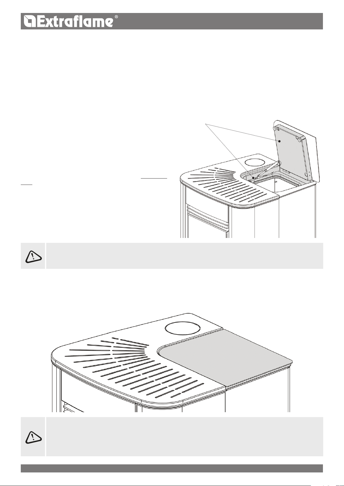
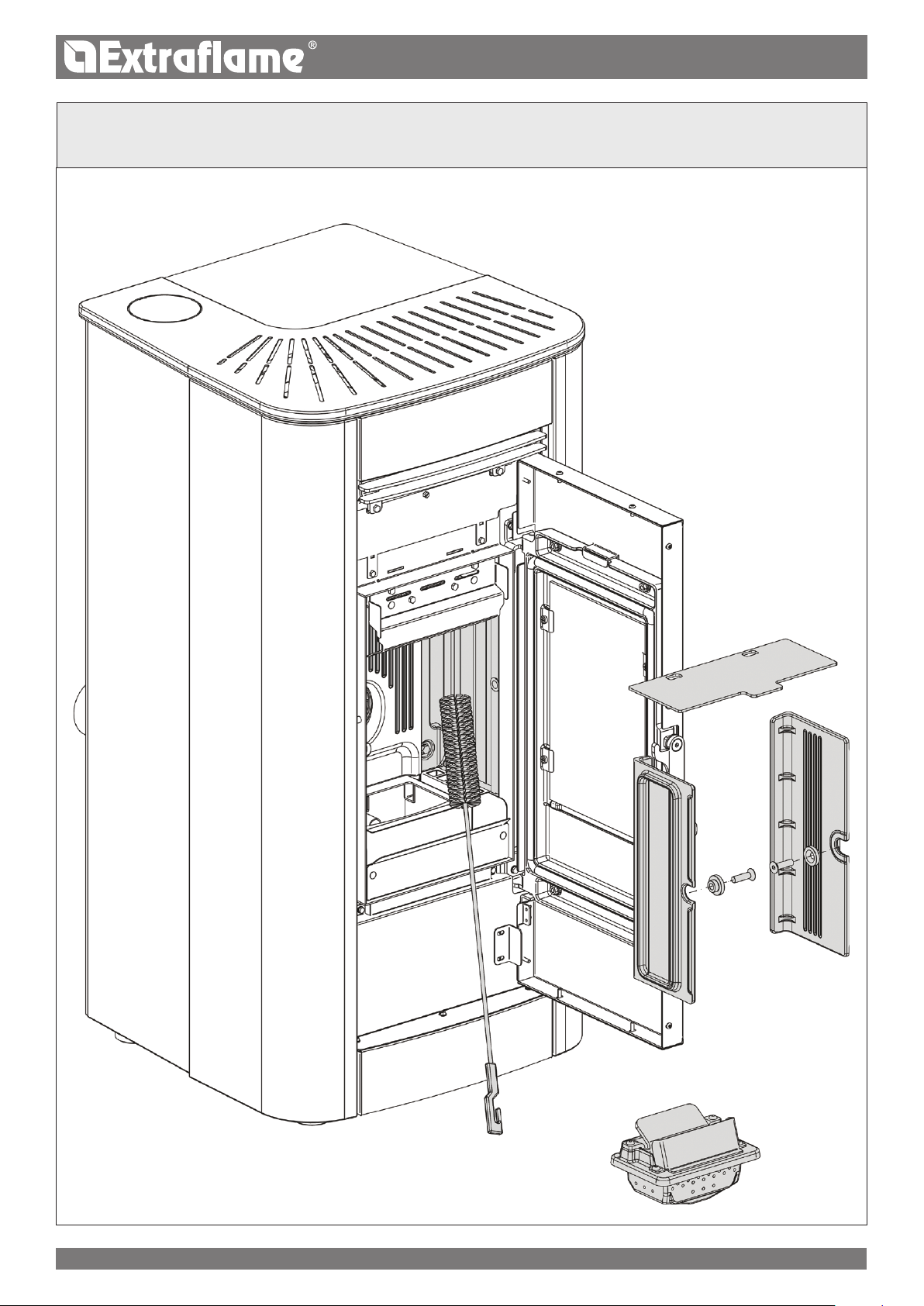
notEs FoR CoRRECt oPERAtIon
The following indications must be respected for correct pellet
stove operation:
Both during stove operation and when it is not used, all hatches
(pellet hopper, door, ash drawer) must remain closed at all times.
They can be opened only for the time required to load the fuel
and for maintenance.
Failure to comply with the above during operation will cause the
display to show the following:
"CLosE HoPPER - stovE DooR"
This indication means that you have 60 seconds to close the
hatch/door and the pellet lid.
Once 60 seconds have passed, during ignition the stove will
go into "DEPR ALARM" mode, while during normal operation
the stove will go into "COOLING STAND BY" mode before
automatically resuming operation once the conditions are
satised (cold stove, etc.).
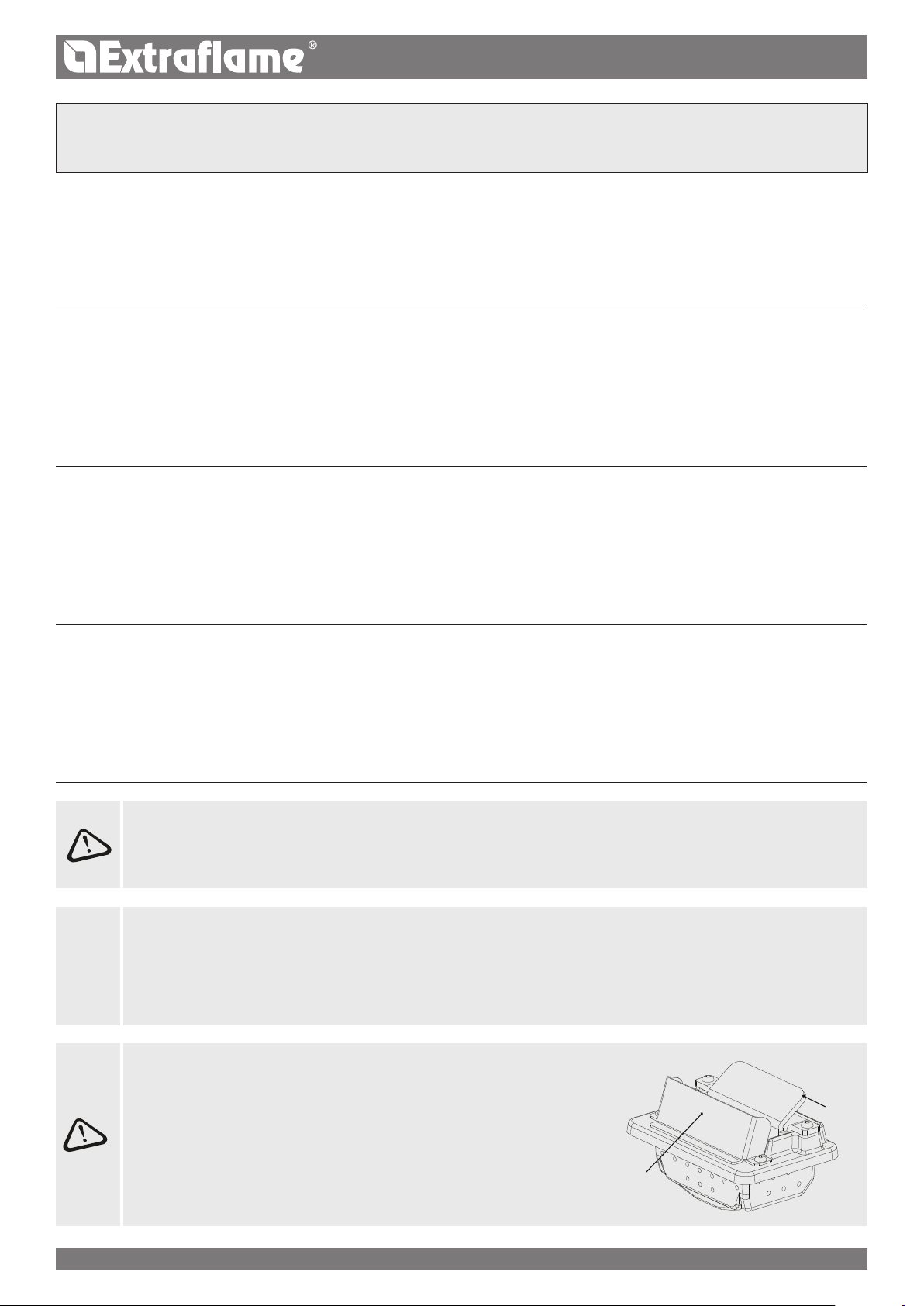
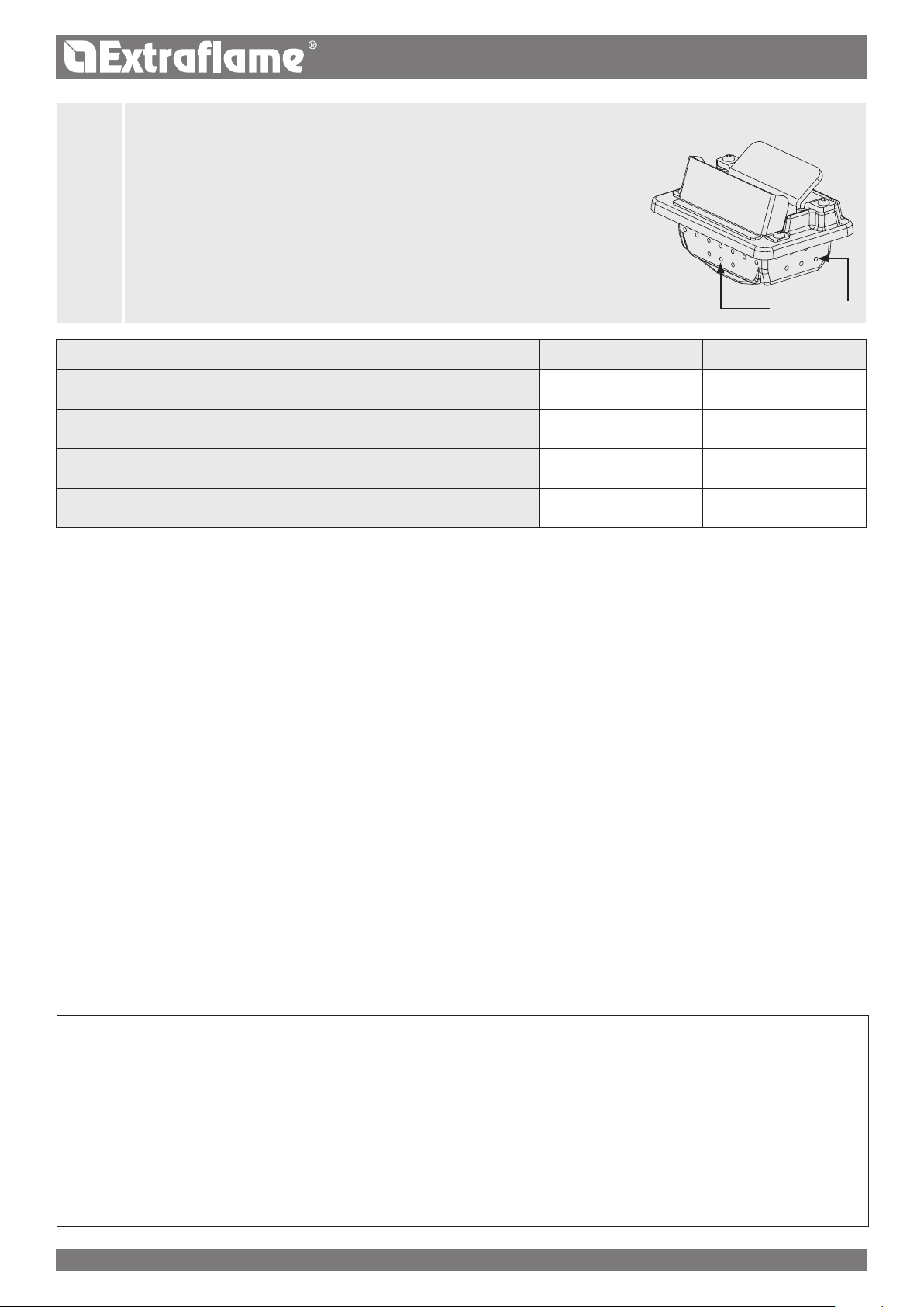
BULB tHERMostAt
REACtIvAtIon
The gure shows the position of the hopper safety
thermostat.
It is recommended to contact the qualied
technician if one of the thermostats is triggered, so
as to verify the cause.
FUsE
If the stove is not powered, have the condition of
the fuse checked by a qualied technician.
Pellet hopper lid
Fire door
16ENGLISH
THE USE OF POOR QUALITY PELLETS OR ANY OTHER MATERIAL WILL COMPROMISE STOVE FUNCTIONS, VOIDING
THE WARRANTY AND RELEASING THE MANUFACTURER OF LIABILITY.
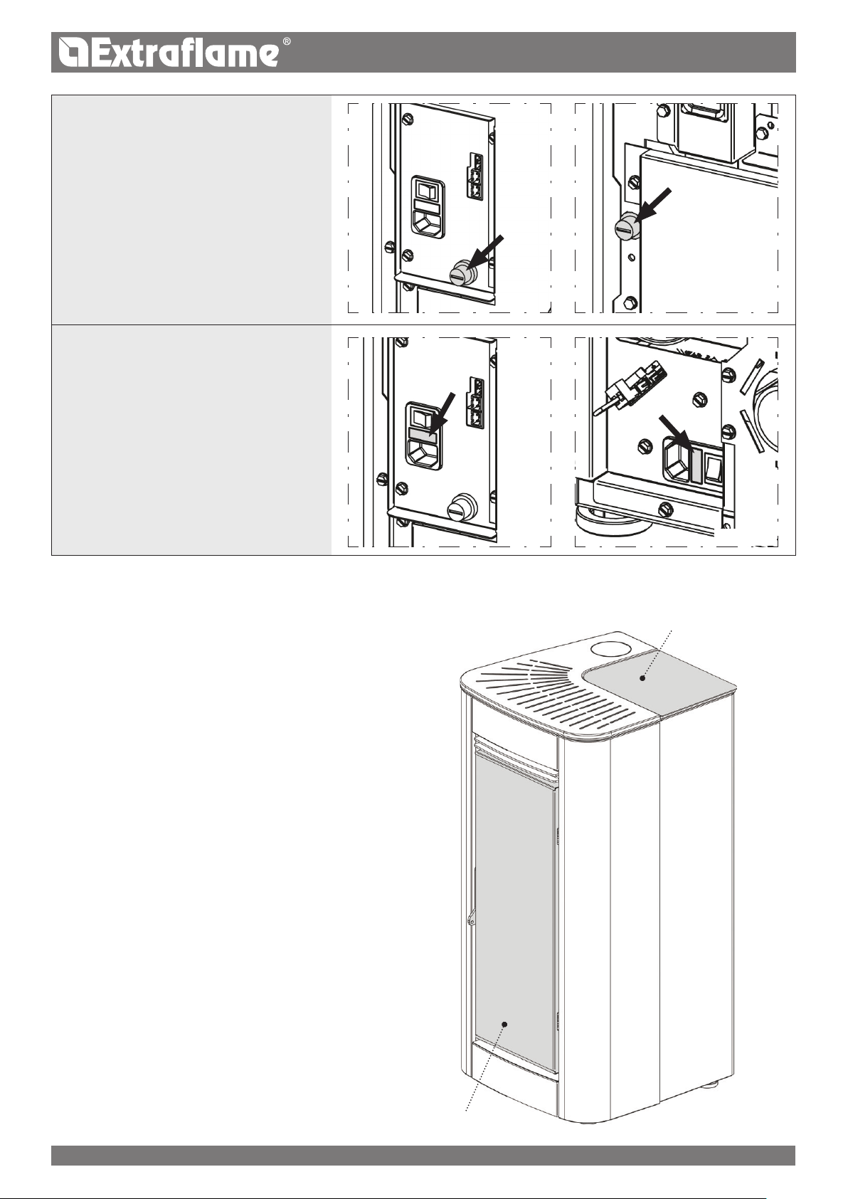
PELLET HOPPER
During stove operation, the pellet hopper lid must always be closed.
Keep clean
Do not place the bag Directly on the stove to loaD the tank.
always use a scoop to loaD the tank. Do not rub or place weights on the tank seal. keep the tank cover
seal supporting surface clean at all times. check the conDitions of the seal frequently. if DamageD,
contact your local authoriseD technician.
PELLETS AND LOADING
Pellets are made by subjecting wood shavings i.e. the rejects of pure unpainted wood from sawmills, carpentry products and products from
other activities connected to wood working and transformation, to very high pressures.
This type of fuel is fully ecological as no glues are used for its compaction. In fact, pellet compactness is guaranteed over time by a natural
substance found in wood: lignin.
In addition to being an ecological fuel, making best use of wood residue, pellets also have a series of technical advantages.
While wood has a caloric value of 4.4 kWh/kg (with 15% moisture, therefore after approximately 18 months of curing), that of pellets is 5
kWh/kg.
Pellet density is about 650 kg/m3 and water content is equal to 8% of its weight. For this reason pellets do not need to be cured to obtain a
sucient heat yield.
The pellets used must be class A1 certied according to standard
ISO 17225-2 (ENplus-A1, DIN Plus or NF 444 of the following
Gebruikershandleiding.com neemt misbruik van zijn services uitermate serieus. U kunt hieronder aangeven waarom deze vraag ongepast is. Wij controleren de vraag en zonodig wordt deze verwijderd.
Product:
Spelregels forum
Om tot zinvolle vragen te komen hanteren wij de volgende spelregels:
lees eerst de handleiding door;
controleer of uw vraag al eerder door iemand anders is gesteld;
probeer uw vraag zo duidelijk mogelijk te stellen;
heeft u een probleem en al geprobeerd om dit op te lossen, vermeld dit erbij aub;
heeft u een oplossing gekregen van een bezoeker dan horen wij dat graag in dit forum;
wilt u een reactie geven op een vraag of antwoord, gebruik dan niet dit formulier maar klik op de knop 'reageer op deze vraag';
uw vraag wordt direct op de website gezet; vermijd daarom persoonlijke gegevens in te vullen;
Belangrijk! Als er een antwoord wordt gegeven op uw vraag, dan is het voor de gever van het antwoord nuttig om te weten als u er wel (of niet) mee geholpen bent! Wij vragen u dus ook te reageren op een antwoord.
Belangrijk! Antwoorden worden ook per e-mail naar abonnees gestuurd. Laat uw emailadres achter op deze site, zodat u op de hoogte blijft. U krijgt dan ook andere vragen en antwoorden te zien.
Abonneren
Abonneer u voor het ontvangen van emails voor uw Extraflame Ilary Plus bij:
nieuwe vragen en antwoorden
nieuwe handleidingen
U ontvangt een email met instructies om u voor één of beide opties in te schrijven.
Ontvang uw handleiding per email
Vul uw emailadres in en ontvang de handleiding van Extraflame Ilary Plus in de taal/talen: Engels als bijlage per email.
De handleiding is 15.7 mb groot.
U ontvangt de handleiding per email binnen enkele minuten. Als u geen email heeft ontvangen, dan heeft u waarschijnlijk een verkeerd emailadres ingevuld of is uw mailbox te vol. Daarnaast kan het zijn dat uw internetprovider een maximum heeft aan de grootte per email. Omdat hier een handleiding wordt meegestuurd, kan het voorkomen dat de email groter is dan toegestaan bij uw provider.
Uw handleiding is per email verstuurd. Controleer uw email
Als u niet binnen een kwartier uw email met handleiding ontvangen heeft, kan het zijn dat u een verkeerd emailadres heeft ingevuld of dat uw emailprovider een maximum grootte per email heeft ingesteld die kleiner is dan de grootte van de handleiding.
Er is een email naar u verstuurd om uw inschrijving definitief te maken.
Controleer uw email en volg de aanwijzingen op om uw inschrijving definitief te maken
U heeft geen emailadres opgegeven
Als u de handleiding per email wilt ontvangen, vul dan een geldig emailadres in.
Uw vraag is op deze pagina toegevoegd
Wilt u een email ontvangen bij een antwoord en/of nieuwe vragen? Vul dan hier uw emailadres in.