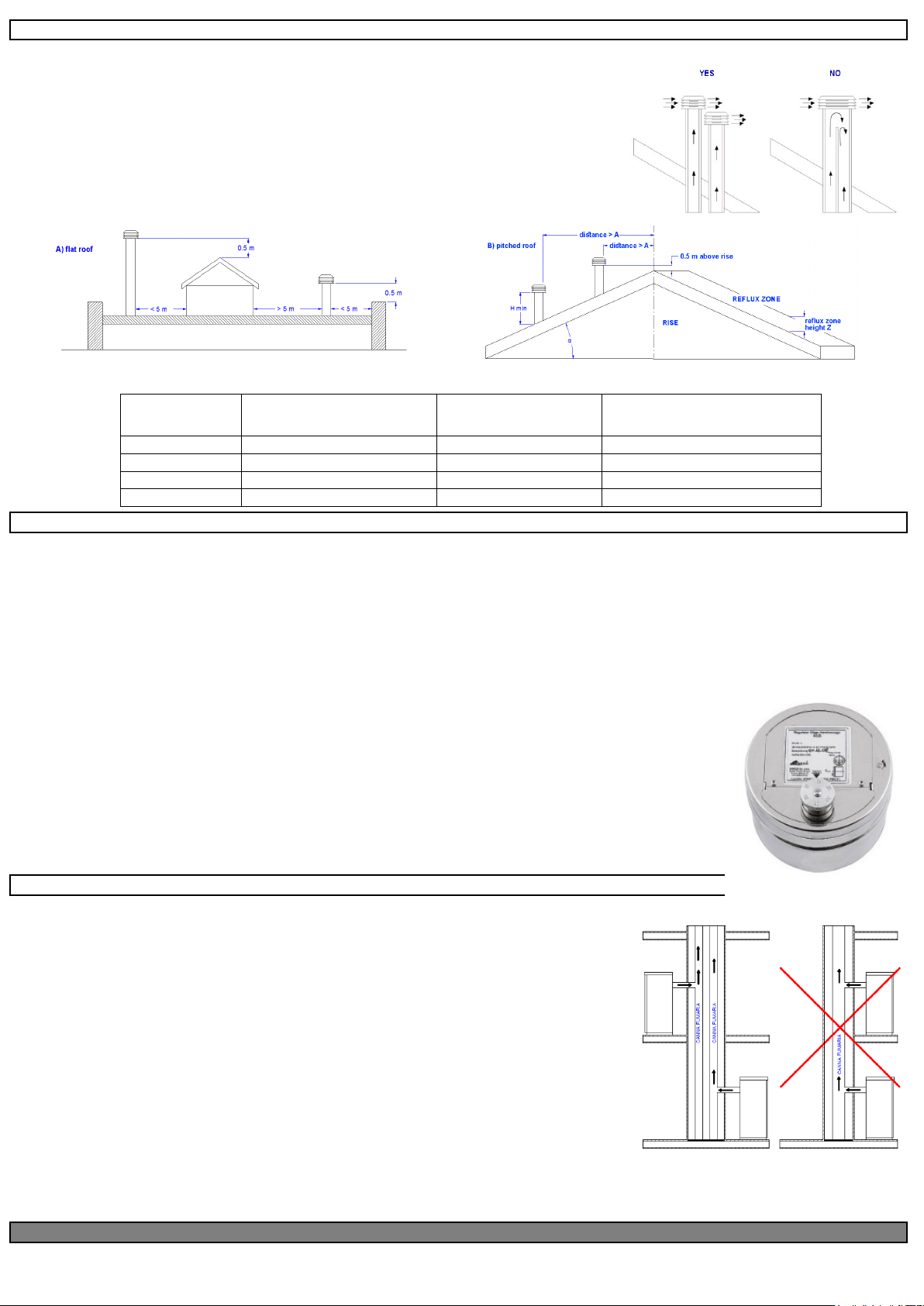
A properly installed chimney cowl ensures optimum stove operation. The anti-downdraught chimney cowl consists of a number of components whose outlet
section sum always doubles the flue pipe section. Make sure the chimney cowl is at least 150cm above the
roof rise so that it is fully exposed to the wind.
The chimney cowls must:
•have useful outlet section that is at least twice that of the flue pipe.
•be made in such a way as to prevent the penetration of rain or snow.
•be constructed in such a way as to ensure, in the event of winds coming from any direction, the evacuation
of combustion products.
•be free of mechanical intake auxiliaries.
05.2 DRAUGHT
As they heat up, the gases formed during combustion undergo an increase in volume and, as a result, have a lower density thanthe cooler surrounding air.
This difference in temperature between the inside and outside of the flue results in a negative pressure which increases proportionally with the flue pipe length
and the temperature.
The draught must be stronger than the fume circulation resistance so that all exhaust fumes generated during combustion inside the stove are drawn upwards
through theoutlet and the flue pipe. There are many meteorological factors that influence the operation of a flue pipe, rain, fog, snow,altitude, but the most
important is the wind, which can cause negative thermal pressure as well as dynamic negative pressure.
Wind action varies depending on whether it is ascending, descending or horizontal.
•An ascending wind always results in increasing the pressure and draught.
•A horizontal wind results in an increased negative pressure as long as the chimney cowl is properly installed.
•A descending wind always reduces the negative pressure, and sometimes inverts it.
Excess draught causes an increase in the combustion temperature and consequently a loss in stove efficiency.
Some of the combustion gases, as well as small particles of combustible material, are drawn into the flue pipe before being burned,
reducing the stove's efficiency, increasing the consumption of pellets and causing the emission of polluting smoke.
At the same time, the high fuel temperature, due to an excess of oxygen, wears the combustion chamber prematurely.
A poor draught, however, slows combustion resulting in a decrease in the stove temperature, fume egress inside rooms, a loss of
stove efficiency and hazardous build-up in the flue pipe.
To avoid excessive draughts, it is advisable to use a draught regulator (see figure to the side).
05.3 EFFICIENCY OF THE HYDRO/BOILER STOVE
Paradoxically, highly efficient stoves may pose difficulties for fume extraction.
In order for a flue pipe to work properly, its internal temperature must increase as a consequence of the fumes
generated during combustion.
The efficiency of a stove is then determined by its ability to transfer most of the heat produced into the room to
be heated: it follows that the greater the efficiency of the stove, the cooler the combustion smoke residues are
and, as a result, the weaker the draught.
A traditional chimney flue, with an approximate design and insulation, is more efficient when used with a
traditional open fireplace or a poor-quality stove where most of the heat is lost with the fumes.
Therefore, purchasing a quality stove often entails modifying the existing chimney flue to obtain a better
insulation, even when it already works properly with old appliances.
Poor draught results in the stove not operating when hot or in smoke spillage.
•Connecting the stove pipe to an existing chimney flue that has already been used with an old appliance is
a common mistake. In this way two solid-fuel appliances share the same chimney flue, which is wrong and
dangerous.
•If the two appliances are used simultaneously, the total fume load might exceed the existing chimney flue
capacity resulting in downdraught. If only one appliance is used, the fume heat will facilitate the draught
but the cold air from the other appliance not in use will cool down exhaust fume temperature again choking the draught.
•Besides the problems described so far, if the two appliances are placed on different levels the communicating vessel principle might be interfered with, causing
combustion fumes to be drawn in an irregular and unforeseeable way.
Gebruikershandleiding.com neemt misbruik van zijn services uitermate serieus. U kunt hieronder aangeven waarom deze vraag ongepast is. Wij controleren de vraag en zonodig wordt deze verwijderd.
Product:
Spelregels forum
Om tot zinvolle vragen te komen hanteren wij de volgende spelregels:
lees eerst de handleiding door;
controleer of uw vraag al eerder door iemand anders is gesteld;
probeer uw vraag zo duidelijk mogelijk te stellen;
heeft u een probleem en al geprobeerd om dit op te lossen, vermeld dit erbij aub;
heeft u een oplossing gekregen van een bezoeker dan horen wij dat graag in dit forum;
wilt u een reactie geven op een vraag of antwoord, gebruik dan niet dit formulier maar klik op de knop 'reageer op deze vraag';
uw vraag wordt direct op de website gezet; vermijd daarom persoonlijke gegevens in te vullen;
Belangrijk! Als er een antwoord wordt gegeven op uw vraag, dan is het voor de gever van het antwoord nuttig om te weten als u er wel (of niet) mee geholpen bent! Wij vragen u dus ook te reageren op een antwoord.
Belangrijk! Antwoorden worden ook per e-mail naar abonnees gestuurd. Laat uw emailadres achter op deze site, zodat u op de hoogte blijft. U krijgt dan ook andere vragen en antwoorden te zien.
Abonneren
Abonneer u voor het ontvangen van emails voor uw Eva Calor TEK 80 bij:
nieuwe vragen en antwoorden
nieuwe handleidingen
U ontvangt een email met instructies om u voor één of beide opties in te schrijven.
Ontvang uw handleiding per email
Vul uw emailadres in en ontvang de handleiding van Eva Calor TEK 80 in de taal/talen: Engels als bijlage per email.
De handleiding is 2.55 mb groot.
U ontvangt de handleiding per email binnen enkele minuten. Als u geen email heeft ontvangen, dan heeft u waarschijnlijk een verkeerd emailadres ingevuld of is uw mailbox te vol. Daarnaast kan het zijn dat uw internetprovider een maximum heeft aan de grootte per email. Omdat hier een handleiding wordt meegestuurd, kan het voorkomen dat de email groter is dan toegestaan bij uw provider.
Uw handleiding is per email verstuurd. Controleer uw email
Als u niet binnen een kwartier uw email met handleiding ontvangen heeft, kan het zijn dat u een verkeerd emailadres heeft ingevuld of dat uw emailprovider een maximum grootte per email heeft ingesteld die kleiner is dan de grootte van de handleiding.
Er is een email naar u verstuurd om uw inschrijving definitief te maken.
Controleer uw email en volg de aanwijzingen op om uw inschrijving definitief te maken
U heeft geen emailadres opgegeven
Als u de handleiding per email wilt ontvangen, vul dan een geldig emailadres in.
Uw vraag is op deze pagina toegevoegd
Wilt u een email ontvangen bij een antwoord en/of nieuwe vragen? Vul dan hier uw emailadres in.