1. The warranty is valid in the presence of a certified installation by AUTHORIZED PERSONNEL.
2. DO NOT TURN THE PRODUCT UPSIDE DOWN or LAY IT IN A HORIZONTAL POSITION during transportation and installation.
3. Stove installation must be carried out by qualified staff and pursuant to the regulations in force in the relevant country.
4. EMPTY THE BURN POT before trying to switch the stove back on in case of ignition failure or power outage. Failure to do so may also result in the breaking
of the door glass.
5. DO NOT POUR PELLETS BY HAND in the burn pot to facilitate stove's ignition.
6. Should any anomaly concerning the flame be detected or, however, in any other case, NEVER SWITCH OFF the stove by disconnecting it from the mains. Use
the relevant button. Disconnecting the stove from the mains will prevent exhaust fumes from being extracted.
7. Should ignition phase take longer than expected (due to damp or poor quality pellets) generating excessive smoke in the combustion chamber, open the door
to expel it, while remaining in a position that guarantees your safety.
8. It is highly important to use GOOD QUALITY CERTIFIED PELLETS. The manufacturer declines any liability for any malfunctioning or damage to mechanical
parts due to the use of poor quality pellets.
9. The burn pot and the combustion chamber MUST BE CLEANED DAILY. The manufacturer declines any liability for any malfunctioning due to a failure to do
so.
Eva Stampaggi S.r.l. declines any liability for any damage to persons or property arising from the failure to comply with the points mentioned above and from
non-compliant product installation.
2
F-1
F-2
F-3
F-4
3
F-5
F-6
F-7
14:24
26.0 p-3
spento
LUNEDI’ 07/03/2016
11:54
18.2° C
Spento
12
A NORMALE
34
4
TABLE OF CONTENTS
01. PRODUCT SAFETY …………..………………………………………………………………………………………………….….. p. 6
02.01 CHIMNEY COWL ……………………………………………………………………………………………………………. p. 8
02.02 DRAUGHT……………………………………………………………………………………………………..……………… p. 9
02.03 STOVE EFFICIENCY………………………………………………………………………………………………………… p. 9
03. WARNINGS ISTALLATION ………………………………………………………………………………………………………….. p. 9
04. INSTALLATION…………………………….………………………………………………………………………………………….. p. 12
04.01 PELLET STOVES………………….………………………………………………………………………………………… p. 12
04.02 PELLET STOVES with OVEN ……………………………………………………………………………………………… p. 12
04.03 PELLET INSERTS …………………………………………………………………………………………………………… p. 12
04.04 PELLET KITCHEN……………………..…………………………………………………………………………………….. p. 13
04.05 PELLET KITCHEN with OVEN………………………..…………………………………………………………………….. p. 13
04.06 AIR STOVE …………………………………………………………………………………………………………………… p. 14
04.07 AIR-TIGHT STOVES ………………………………………………………………………………………………………… p. 15
05. PRODCT USE …………………..……………………………………………………………………………………………………… p. 15
05.01 ELECTRONICS WITH 6 BUTTON LED DISPLAY………………………………………………………………………… p. 15 p. 3 F-1
(Pellet inserts – Canalized pellet stove)
05.02 ELECTRONICS WITH 6 BUTTON LCD DISPLAY ………………………………………………………………………… p. 17 p. 3 F-2 F-3
(Pellet stoves)
05.03 ELECTRONICS WITH 3 BUTTON LED DISPLAY N. 100………………………………………………………………… p. 19 p. 3 F-4
(Pellet stoves – Pellet stove with oven – Pellet kitchen – Pellet kitchen with oven)
05.04 ELECTRONICS WITH 6 BUTTON LED DISPLAY N. 100………………………………………………………………… p. 22 p. 3 F-1
(Pellet stoves – Pellet inserts)
05.05 ELECTRONICS WITH REMOTE CONTROL ……………………………………………………………………………… p. 24 p. 4 F-5
(Pellet stoves)
05.06 ELECTRONICS WITH REMOTE CONTROL LCD…………………. …………………………………………………….. p. 26 p. 4 F-6
(Air-tight stoves)
05.07 ELECTRONICS WITH REMOTE CONTROL LCD ………………..…….………………………………………………… p. 28 p. 4 F-6
(Air stove)
05.08 IR REMOTE CONTROL (OPTIONAL)………………………………………………………………………………………. p. 31
(Pellets stoves - Pellet stove with oven – Pellet kitchen – Pellet kitchen with oven – Pellet inserts)
06. CLEANING AND MAINTENANCE …………………………………………………………………………………………………….. p. 31
07. TROUBLESHOOTING……………………….………………………………………………………………………………………….. p. 32
08. YEARLY SCHEDULED MAINTENANCE …………………………………………………………………………………………….. p. 33
09. WARRANTY CERTIFICATE ……………………………………………………………………………………………………………. p. 34
10. CERTFICATE OF INSTALLATION AND TESTING ......…………………………………………………………………………….. p. 35-36
5
01. PRODUCT SAFETY
SAFETY WARNINGS
The stoves were built in compliance according to standard EN13240 (wood stoves), EN 14785 (pellet stoves) and EN 12815 (kitchens and wood-burning stoves)
using high quality and non-polluting materials. To make better use of your stove it is advisable to follow the instructions in this booklet.
Read this manual carefully before use or any maintenance operation.
Eva Stampaggi aims to provide as much information as possible to ensure safer use and to avoid damage to persons, property or parts of the stove itself.
Each stove is subjected to internal testing before shipment and as such residues inside the appliance may be found.
RETAIN THIS MANUAL FOR FUTURE REFERENCE.
FOR ANY REQUIREMENT OR CLARIFICATION PLEASE CONTACT
THE AUTHORISED RETAILER
•Installation and connection must be carried out by qualified staff in compliance with local regulations, national and European standards (UNI 10683) and with
the annexed installation instructions. Furthermore, these operations must be performed by personnel who are authorised and professionally trained for the
task in question.
•The combustion of waste, especially of plastic materials, damages the stove and the vent pipe. Moreover, it is forbidden by the law against the emission of
harmful substances.
•Do not use alcohol, petrol or other highly inflammable liquids to light the fire or poke it during operation.
•Do not introduce into the stove an amount of fuel greater than that recommended in this booklet.
•Do not modify the product.
•It is forbidden to use the appliance with the door open or the glass broken.
•Do not use the appliance as, for example, a clothes drying rack, a bearing surface or step etc.
•Do not install the stove in bedrooms or bathrooms if not certified as watertight.
The pellets to be used are the following:
The pellet stoves operate exclusively with pellets made from various types of legislative-compliant wood.
DIN plus or EN plus 14961-2 A1 or PEFC/04-31-0220 or ONORM M7135 or having the following characteristics:
Min calorific value 4.8 kWh/kg (4180 kcal/kg)
Density 630-700 kg/m3
Maximum humidity 10% of the weight
Diameter: 6 ±0.5 mm
Percentage ash: max 1% of the weight
Length: min 6 mm- max 30 mm
Composition: 100% untreated wood from the industry of wood or post-consumption without the addition of binders, bark-free and compliant with current
regulations.
GENERAL SAFETY PRECAUTIONS
•Use the stove only as described in this manual. Any other use not recommended by the manufacturer may cause fires or accidents to people.
•Make sure that the electrical power available corresponds to the value indicated on the data plate (220V~/50Hz).
•This appliance is not a toy. Make sure children are not left unattended and do not use the appliance as a toy.
•This device is not intended for use by persons (including children) with reduced physical or mental capacity, or without specific experience and knowledge,
unless supervised or duly instructed on the use of the appliance by a person responsible for their safety.
•Disconnect the appliance from the mains when not in use or during cleaning operations.
•To do so, turn the switch to the O position and disconnect the plug from the socket. Pull the plug, not the cable.
•Never block the combustion air inlets and fume outlets.
•Since the stove is fitted with electrical components, do no touch it with wet hands.
•Do not use the appliance in case of damaged cables or plugs. The device is classified as type Y: the power supply cable may only be replaced by a
qualified technician. Should the power supply cable be damaged, it can be replaced only by the manufacturer or by its technical assistance service
or by a similarly qualified person.
•Do not place any object on the cable and do not bend it.
•Avoid using extension cables as their temperature may increase excessively posing fire hazards. Never use one single extension cable to power several
appliances.
•During normal functioning some parts of the stove may become extremely hot, such as the door, the glass or the handle. Be careful, especially with
children. Do not touch any hot parts if not wearing adequate protective devices.
•ATTENTION! DO NOT TOUCH the FIRE DOOR, the GLASS, the HANDLE or the FUME OUTLET DURING FUNCTIONING if not wearing adequate
protective devices since they become extremely hot.
•Keep inflammable materials, such as furniture, cushions, pillows, blankets, paper, clothing, curtains, etc., at least 1,5 m away from the stove front and 30 cm
from the stove sides and back.
•The stove that is covered by or in direct contact with inflammable materials, including curtains, blankets, etc., during normal operation may result in a fire
hazard. KEEP THE APPLIANCE AWAY FROM THE MATERIALS MENTIONED ABOVE.
•Do not immerse the cable, plug or any other appliance component in water or other liquids.
•Do not use the stove in dusty environments or wherever inflammable vapours are generated (e.g. in a workshop or garage).
•The stove is fitted with components that generate arcs and sparks. Do not install the stove in areas posing a significant fire or explosion hazard due to a high
chemical substance concentration or to a high humidity level.
•Do not use the appliance close to bathtubs, showers, basins, sinks or swimming pools.
•Do not install the appliance underneath an air vent. Do not install the stove outdoors.
•Do not repair, disassemble or modify the appliance. The appliance is not fitted with components that can be repaired by users.
•Turn off the stove, disconnect it from the mains and wait until it has cooled down completely before performing any maintenance operations.
•WARNING: DISCONNECT THE STOVE FROM THE MAINS BEFORE PERFORMING MAINTENANCE OPERATIONS.
•ATTENTION! These stoves operate exclusively on pellets and possibly also pits if the stove has this option; DO NOT USE OTHER FUELS: any other
material that may be burnt will result in failure and malfunction of the appliance.
•Keep the pellets in a fresh dry place: storing pellets in a place that is damp or excessively cold may reduce the stove potential heat output. Be
careful when storing and handling pellet bags to prevent pellet crushing and consequent sawdust production.
•The fuel consists of small cylinders with 6-7mm diameter and a maximum length of 30mm. Their maximum moisture content is equal to 8%. This stove is
designed to burn pellets made of compacted sawdust obtained from different types of wood, in compliance with environment protection legislation.
•The use of different types of pellets may result in a slight, sometimes even undetectable, change in the stove efficiency. This change can be counterbalanced
by increasing or decreasing the stove heat output by only one step.
•Clean the burn pot on a regular basis upon every ignition or pellet refuelling.
•Open the firebox only upon refuelling or removal of residues to prevent fumes from escaping.
•Do not switch the stove on and off intermittently to avoid damaging its electrical and electronic components.
•Do not use the appliance as waste incinerator or for any other purpose other than the intended one.
•Do not use liquid fuels.
•Do not modify the appliance without prior authorization.
•Use only original spare parts recommended by the manufacturer.
6
•Make sure that the stove is transported in compliance with safety regulations.
Avoid any improper transfers or knocks that may damage the ceramics or the structure.
•The metal structure is coated using high temperature paints. When using the appliance for the first few times, unpleasant odours may be given off due to the
paint of the metal parts that is drying: this is in no way dangerous and in such case, simply ventilate the premises. After the first heating cycles, the paint will
reach its maximum adhesion and all its chemical and physical features.
•The reload the hopper, simply open the access lid and pour in the pellets, also during normal operation, making sure that no pellets fall out of it. Always refuel
the hopper before leaving the operating stove unattended for long periods of time.
•Whenever the hopper and the auger tube become completely empty, the appliance will be automatically switched off. It may take two separate ignitions to
resume operation at ideal working conditions as the auger tube is very long.
•ATTENTION! If the stove is not properly installed, power outages may result in fume spillages. Under specific circumstances, an uninterrupted
power supply unit must be installed.
•ATTENTION! Being a heating appliance, some parts of the stove can become extremely hot. We therefore recommend paying special attention
during operation.
WHEN THE STOVE IS WORKING:
odo not open the door;
odo not touch the door glass since it becomes extremely hot;
okeep children away from it;
odo not touch the fume outlet;
odo not pour any liquid inside the firebox;
odo not perform any maintenance operations if the stove is not cold;
oonly qualified technicians are allowed to perform any operation;
ofollow all the instructions contained herein.
INTRODUCTION
INSTALLATION WITH WALL FUME OUTLET IS PROHIBITED. INSTEAD THE FUME OUTLET MUST BE ROOF-TYPE AS PROVIDED FOR BY NATIONAL
REGULATIONS.
Eva Stampaggi S.r.l. declines any liability for any damage to persons or property arising from the failure to comply with the points mentioned above
and from non-compliant product installation.
Install the stove according to the regulations in force in the country of use.
For example, in Italy this refers to UNI 10683: 2012, which dictates 4 points
1. preliminary activities - for which the retailer/installer is responsible and liable for at the time of the inspection before definitive installation. The preliminary
activities include:
•installation site suitability verification;
•fume evacuation system suitability verification;
•external air inlet suitability verification;
At this stage, it is necessary to check that the product can be safely operated and that it satisfies the relevant technical characteristics.
The safety conditions must be ascertained by means of a prior inspection.
Stoves and fireplaces are heating systems and must be installed safely and comply with the manufacturer's instructions!
2. Installation - responsibility of the installer. At this phase, the aspects of installation of the product and of the fume evacuation system are taken into account
and the following issues are addressed:
•safety distance from combustible materials;
•chimney flue construction, smoke ducts, intubated systems and chimney cowls.
3. issuing of additional documents - responsibility of the installer.
Issuing of the technical documentation must include:
•manual of use and maintenance of the appliance and of the components of the system (e.g. smoke ducts, chimney flue, etc.);
•Photocopy or photograph of the chimney flue plate;
•system manual: (if applicable);
•Declaration of Conformity in relation to Ministerial Decree 37/08.
4. control and maintenance - responsibility of the maintenance technician who must oversee protection and maintenance of the product during its operation over
time. The operator in charge of control and maintenance of the systems for winter and summer climate control performs these activities to a professional standard
in accordance with the regulations in force. The operator, at the end of these operations, must draw up and sign a technical inspection report in accordance with
the models provided by the provisions of this decree and the implementing rules, in relation to the type and capacity of the system, to be issued to the person who
signs a copy thereby confirming receipt and reading thereof."
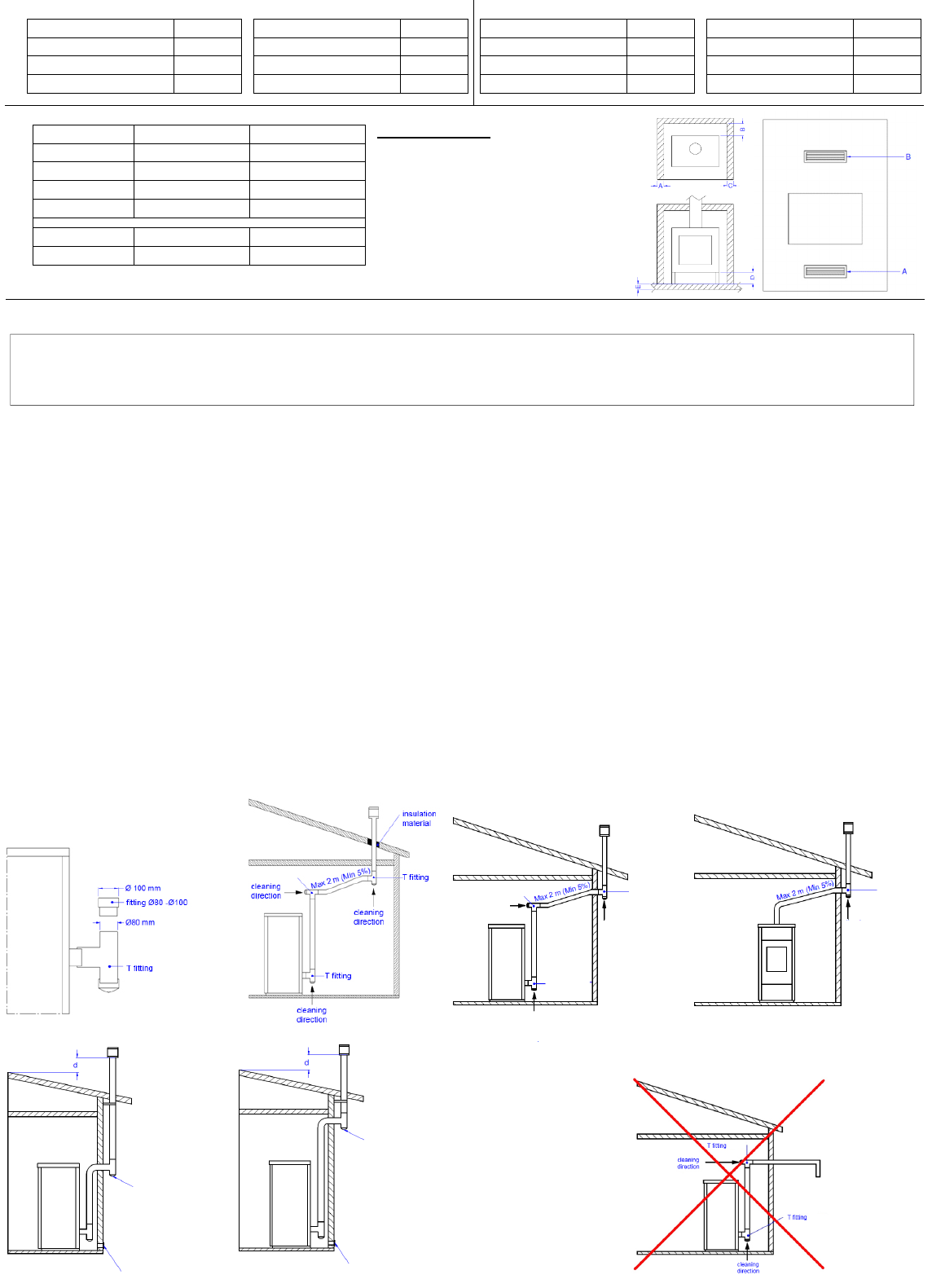
02. VENT PIPE
THE PRODUCTION OF THE STOVES IS REQUIRED WITH HIGHER PERFORMANCES, SO IT IS IMPORTANT TO PERFORM THE INSTALLATIONS
ACCORDING TO THE LAW. IF THE FLUE DUCT PASSES THROUGH NON-HEATED AREAS, IT MUST BE INSULATED FOR A PROPER COMBUSTION.
A properly installed chimney cowl ensures optimum stove functioning. The anti-downdraught chimney cowl
consists of a number of components whose outlet section sum always doubles the vent pipe section. Make sure
the chimney cowl is at least 150cm above the roof top so that it is fully exposed to the wind.
The chimney cowls must:
•have useful outlet section that is at least twice that of the vent pipe.
•be made in such a way as to prevent the penetration of rain or snow.
•be constructed in such a way as to ensure, in the event of winds coming from any direction, the evacuation
of combustion products.
•be free of mechanical intake auxiliaries.
Examples of vent pipe
Steel vent pipe with double chamber insulated with
material resistant to 400°C. Optimum efficiency.
Refractory vent pipe with insulated double chamber
and external coating in lightweight concrete. Optimum
efficiency.
Avoid vent pipes with internal rectangular section whose ratio
between the larger and smaller side is greater than 1.5. Poor
efficiency
Traditional clay vent pipe with cavities. Optimum efficiency.
External vent with non-
closable grid
Inspection doors
MAX A+1/2A
A
THROTTLE
INCLINATION
LESS THAN 45°
8
Roof pitch
α [°]
Horizontal width of reflux zone
measured from top A axis [m]
Minimum height from roof for discharging
exhaust fumes H min =Z+0.50m
Height of reflux zone Z [m]
15 1.85 1.00 0.50
30 1.50 1.30 0.80
45 1.30 2.00 1.50
60 1.20 2.60 2.10
02.2 DRAUGHT
Fumes heat up during combustion, increasing their volume. Their density is therefore lower than the one of the surrounding colder air.
This difference between the inside and outside temperatures of the chimney results in a negative pressure which increases proportionally to the vent pipe length
and the temperature.
The draught must be stronger than the fume circulation resistance so that all exhaust fumes generated during combustion inside the stove are drawn upwards
through the outlet and the vent pipe. Many weather conditions affect the vent pipe functioning, such as rain, fog, snow, altitude, and wind being the most important
as it can create both negative pressure and dynamic loading.
The wind action varies depending on whether it is ascending, descending or horizontal.
•Ascending wind always results in an increased negative pressure and draught.
•Horizontal wind results in an increased negative pressure as long as the chimney cowl was properly installed.
•Descending wind always diminishes the negative pressure, sometimes inverting it.
Excess draught causes an increase in the combustion temperature and consequently a loss in stove efficiency.
A part of the combustion fumes is drawn up through the vent pipe together with small pellet particles before combustion reducing stove
efficiency, increasing fuel consumption and resulting in the emission of polluting fumes.
At the same time the high fuel temperature, due to an excess amount of oxygen, wears down the combustion chamber sooner than
expected.
On the other hand, poor draught slows down combustion resulting in a decrease in the stove temperature, fume spillage inside the room,
a loss of stove efficiency and dangerous build-up in the vent pipe.
In order to avoid excessive draught it is appropriate to use:
Draught regulator
02.3 STOVE EFFICIENCY
Highly efficient stoves may pose difficulties for fume extraction.
In order for a vent pipe to work properly its internal temperature must increase as a consequence of the fumes
generated during combustion.
Importantly, the efficiency of a heater is determined by its ability to transfer most of the heat produced to the
environment to be heated: consequently, the greater the efficiency of the stove, the "colder" the residual fumes of
combustion, and consequently, the lower the "draft".
A traditional chimney flue, with a rough design and insulation, is more efficient if used with a traditional open fireplace
or a poor quality stove where most of the heat is lost with the fumes.
Therefore, purchasing a quality stove often entails modifying the existing chimney flue to obtain a better insulation,
even when it already works properly with old appliances.
Poor draught results in the stove not operating when hot or in smoke spillage.
•Connecting the stove pipe to an existing chimney flue that has already been used with an old appliance is a
common mistake. In this way two solid-fuel appliances share the same chimney flue, which is wrong and
dangerous.
•If the two appliances are used simultaneously, the fume load might exceed the existing chimney flue capacity resulting in downdraught. If only one appliance
is used, the fume heat will facilitate draught but the cold air coming from the other appliance not in use will cool down exhaust fume temperature again blocking
the draught.
•Besides the problems described so far, if the two appliances are placed on different levels the communicating vessel principle might be interfered with, causing
combustion fumes to be drawn in an irregular and unforeseeable way.
03. WARNINGS ISTALLATION
Using coaxial tubes the air will be pre-warmed contributing to improved combustion and lower
emissions into the atmosphere.
Follow the instructions before installing your stove.
Select the position where the stove is to be installed and:
•Arrange the connection to the vent pipe for fume extraction
•Arrange the external air intake (combustion air)
•Arrange the connection to the earthed mains
•The electrical system of the room where the stove is to be installed must be earthed,
otherwise the control board may not work properly.
•Place the stove on the floor in a convenient position for the connection to the vent pipe
and close to the combustion air intake.
•The appliance must be installed on a floor with an adequate load-bearing capacity.
•Should the existing floor not comply with the requirement above, proper measurements
must be taken (for instance, the installation of a load distribution plate).
VENT PIPE
VENT PIPE
VENT PIPE
9
•All the structures which could catch fire if exposed to excessive heat must be protected.
Floors made from wood or inflammable materials must be protected using non-combustible materials (e.g. 4mm-thick sheet metal or ceramic glass).
•The appliance installation must ensure easy access for cleaning the stove, exhaust pipes and vent pipe.
•This appliance is not suitable to be installed on a shared vent pipe.
•During normal operation, the stove draws air from the room where it is installed. Therefore, an external air intake must be positioned at the same height of the
pipe located on the stove back. Exhaust fume pipes must be suitable for pellet stoves and must therefore be made from coated steel or stainless steel, with a
diameter of 8cm and fitted with adequate gaskets.
•The combustion air intake must be connected directly to the outside or to adjacent rooms provided they are fitted with external air supply vents and are not
used as bedrooms or bathrooms or, whenever a fire hazard exists, as storage rooms, garages, combustible material warehouses, etc. The air vents must be
placed in such a way that they cannot be clogged either from the outside or inside and must be protected using a grille, a metal mesh or other suitable means
provided they do not reduce the minimum section.
•If the stove is to be installed in rooms where it is surrounded by combustible materials (e.g. furniture, wood cladding, etc.), the following minimum clearances
This stove is an air-tight stove. If properly connected by means of a suction tube, these stoves draw the combustion air and the air necessary for glass
cleaning directly from outside and not from the room where they are installed, preserving the oxygen in the room. Using coaxial tubes the air will be pre-
warmed contributing to improved combustion and lower emissions into the atmosphere. Ideal for passive houses, they offer best comfort at the lowest
cost. The stove works even if not connected to the external air intake.
Besides complying with the minimum clearances set above, we also recommend installing heat-resistant fireproof insulating panels (rock wool, cellular concrete,
etc.).
The following is recommend:
Promasil 1000
Classification temperature: 1000 °C
Density: 245 kg/m
3
Shrinkage at reference temperature, 12 h: 1.3/1000°C %
Cold crushing strength: 1.4 MPa
Bending strength: 0.5 MPa
Reversible thermal expansion: 5.4x10
-6
m/mK
•When it is operational, the stove can cause a negative pressure in the room where it is installed. Therefore there should not be in the same room other naked
flame devices, with the exception only of type c stoves (airtight).
•Make sure that the stove can draw the necessary quantity of combustion air: this must be from an open space (i.e. a space without exhaust blowers or
providing adequate ventilation) or directly from outside.
•Do not install the stove in bedrooms or bathrooms.
•Unpack the stove: be careful not to damage the product at the time of unpacking.
•Check the stove's legs and adjust them so that the stove is stable.
•Place the stove so that the door and any window openings are not against the walls.
•After connecting the stove to the combustion air inlet join the coupling device to the vent pipe.
INSTALLATION EXAMPLE:
EXAMPLE OF INCORRECT INSTALLATION:
Exhaust pipes must never be fitted pointing downwards or horizontally so that fumes are discharged directly through the external wall.
11 KW INSERTS 7,5 KW INSERTS
REAR 100 180
LATERAL 100 180
FRONT 1500 1000
FLOOR 50 10
A cm² 500 450
B cm² 500 450
Specific heat capacity: 1.03 Kj/kgK
Thermal conductivity λ:
200 °C 0.07 W/mK
400 °C 0.10 W/mK
600 °C 0.14 W/mK
800 °C 0.17 W/mK
Thickness: 40 mm
T fitting
Cleaning
direction
T fitting
Cleaning
direction
Cleaning
direction
T fitting
T fitting
Cleaning
direction
T fitting
inspection
inspection
External vent with non-
closable grid
External vent with
non-closable grid
Cleaning
direction
11
DESCRIPTION OF PANEL
LED (L0) Room temperature setting
LED (L1) Heat output setting
LED (L2) Chrono
LED (L3) ON/OFF
LED (L4) Alarm
LED (L5) Auger tube/exchanger / ignition plug
THE MENU
Hold P1 button down to access the menu. It includes several items and levels to access settings and control board programming.
Menu M1 – SET CLOCK
Push and hold the (P1) button until you see the M1 writing, confirm with the ON/OFF (P3) button. With the (P1) and (P2) buttons change the current day and push
the power button, set the hour and push ON/OFF (P3), set the minutes and push ON/OFF (P3), set the current day in number and push ON/OFF (P3), set the
current month and push ON/OFF (P3), set the current year and at this point to confirm and exit push and hold the ON/OFF (P3) button until you see the current
hour.
Menu M2 – SET CHRONO
Submenu M2 – 1 CHRONO ENABLE
Push and hold the (P1) button until you see the M1 writing, push the (P2) button until M2, confirm with ON/OFF (P3) and you will see the Menu M2-1, confirm
with ON/OFF (P3) and with the arrow (P1) put ON to activate the general chrono; go back by holding down the ON / OFF (P3) button, and with (P2) choose
the program to be activated.
Submenu M2 – 2 PROGRAM DAY
Two ON-OFF cycles fixed for every day
Submenu M2 – 3 PROGRAM UEEK
Four ON-OFF cycles and for every schedule you must select the days
Submenu M2 – 4 PROGRAM U-END
Two ON-OFF cycles for Saturday and Sunday
Selecting a program
Enter the desired program by pressing once ON / OFF (P3), the first parameter is the enabling of the program; set it to ON by pressing the button (P2) ATTENTION,
ENABLE A PROGRAM AT A TIME TO AVOID PROBLEMS AT THE CHRONO). Press ON / OFF (P3), to set the starting time, and with the keys (P1) and (P2)
to set the hour for the desired start, then press SET (P3) to set the stopping time, and with the arrows (P1) and (P2) set the stop time, only in the weekly program
at this point press SET to confirm the days, and with the ON / OFF button move between the days of the week and with the keys (P1) and (P2) select ON or OFF.
When you set the hours and days to confirm and exit the CHRONO hold the ON-OFF button down to the home screen: if you have properly set up the time
schedules a green LED next to the clock on the top left of the display will light.
Menu M3 – LANGUAGE
Use this function to select one of the languages available. Press P2 (increase) and P1 (decrease) buttons to scroll through the options and press P3 button to
confirm.
Menu M4 – STAND-BY
Use this function to enable or disable the STAND-BY mode. Press P3 button to select menu M4 and then P1 (decrease) or P2 (increase) button to select the ON
or OFF status. Refer to the section concerning the stand-by mode for more details on its functioning.
Menu M5 – BUZZER
Use this function to enable or disable the control board buzzer during alarms. Press P1 or P2 button to enable or disable this function and P3 button to confirm.
Menu M6 – LOAD INITIAL
This function is only available when the stove is switched OFF. It allows the auger tube to be loaded upon the first stove start-up when the pellet hopper is empty.
After selecting menu M6, the message "Pressure inc" will scroll on the display. Then press P2 (increase). The exhaust blower switches on at the maximum speed
and the auger tube (auger tube LED on) starts working. They will switch off once the period of time indicated on the display has elapsed or after pressing P3
button.
Menu M7 – STATE STOVE
After entering menu M7 by pressing P3 button, the status of a few parameters with stove in working mode scrolls on the display. The table below contains an
example of the values scrolling on the display together with their meaning.
Displayed status - meaning
3.1” - Auger tube pellet feeding status 52ʼ - Time out Toff - Thermostat status 106° - Fume temperature 1490 - Exhaust blower speed
Menu M8 – SET TECHNIC
This menu item is reserved to the stove installer. After entering the password, P1 (decrease) and P2 (increase) buttons allow all the stove working parameters to
be set.
Menu M9 – ESCAPE
Select this item by pressing the P3 button to exit the menu and to go back to the previous status.
USER FUNCTIONS
Standard functioning of a control board properly installed on an air stove is described below with reference to the functions available to users.
Stove ignition
First connect the stove plug to the mains and load the pellet hopper.
Be careful not to empty the entire bag at once. Perform this operation slowly.
The combustion chamber and the burn pot must be cleaned, removing any combustion residue. Verify that the hopper lid and the door are closed. Failure to do
so could cause a malfunction of the stove and subsequent related alarms. Upon initial start-up ensure that in the burn pot there are no components that will burn
(feet bag, instructions, etc.).
Hold P3 button down for a few seconds to switch on the stove. The message "START" appears on the display and the ON/OFF LED starts flashing if the stove
has successfully switched on. This phase lasts for the period of time set by Pr01 parameter.
During this phase the stove goes into the pre-heating status: the ignition plug (as indicated by the relevant LED) and the exhaust blower switch on.
Any problem detected during the switching-on phase is indicated on the display and the stove goes into the alarm status.
Pellet feeding
The pellet feeding phase starts after approx. 1 minute: the message "LOAD PELLET" scrolls on the display and the ON/OFF LED starts flashing.
During the first stage the Auger tube feeds the pellets to the burn pot during a period of time set by Pr40 parameter (Auger tube LED on), the exhaust blower
speed is set by Pr42 parameter and the ignition plug is still on (ignition plug LED on).
During the second stage, once the period of time set by Pr40 parameter has elapsed, the auger tube switches off (auger tube LED off) during a period of time set
by Pr41 parameter, while the exhaust blower speed remains as in the previous status.
BUTTON (P1) decrease / menu / room temperature setting
The warranty period is two years if the product was purchased by a private customer (Legislative Decree no. 24, February 2 2002) and one year if it was purchased
by a company or by a professional (subject to VAT).
The tax document referred to the product purchase gives validity to the warranty and the date on it shall be used to calculate the warranty period.
The warranty provided shall be subject to the following terms and conditions:
You can contact the staff in charge of the after-sale procedure by calling 0438.35469 or by sending an email to assistenza@evacalor.it
Our qualified staff will provide you with information concerning technical, installation or maintenance problems.
Should it prove impossible to solve the issue over the phone, our staff will forward it to the Technical Support Service closest to you, which will guarantee assistance
from a technician within 5 working days
Any parts replaced during the warranty period shall be covered for the remaining period of the purchased product warranty.
The manufacturer shall not pay the customer any indemnities for the inconvenience of not being able to use the product during the period required for repairing.
Should it be necessary to replace the product, the manufacturer will deliver it to the retailer who will then deliver it to the end user following the same procedure as
for the product purchase.
This warranty is valid within Italy. Should the product be sold or installed abroad the warranty shall be recognised by the distributor in charge of the relevant territory.
This warranty covers the repair or replacement of faulty parts or components or of the entire product at our sole discretion.
Whenever you require assistance, you may be asked to provide:
•Serial number
•Stove model
•Purchase date
•Purchase location
•Warranty activation certificate filled in by an authorised Technical Assistance Centre
The warranty shall not cover:
•Non-compliant installation or installation carried out by non-qualified staff (UNI10683 and UNI EN 1443);
•Use of non-certified pellets;
•Improper use, such as keeping the stove switched on for too long at maximum heat output;
•Annual stove maintenance carried out by someone other than one of our authorised Technical Assistance Centres;
•Vent pipe cleaning not carried out;
The warranty will not cover the following differences due to the natural features of the covering materials:
•Veining is a main feature of stone guaranteeing its uniqueness;
•Any small cracks or cracking in ceramic or majolica surrounds;
•Any shade or tone differences in ceramic or majolica surrounds;
•Door glass;
• Gaskets;
•Ignition plug heating elements (warranty period: 1 year);
•The warranty does not cover masonry works;
•Damage to chromed and/or anodised and/or painted metal parts or on any other treated surfaces due to rubbing or bumping with other metal parts;
•Damage to chromed and/or anodised and/or painted metal parts or on any other treated surfaces due to improper maintenance and/or cleaning using chemical
products or agents (said parts must be cleaned using only water);
•Damage to mechanical components or parts due to improper use or to installation carried out by non-qualified staff or not in compliance with the instructions
provided with the product;
•Damage to electrical or electronic parts or components due to improper use or to installation carried out by non-qualified staff or not in compliance with the
instructions provided with the product.
Attention: after purchase, please keep this warranty certificate together with the original package, installation and testing certificate and the retailer
receipt.
IMPORTANT:
EVA STAMPAGGI ADVISES TO CONSULT WITH ITS AUTHORIZED DEALERS AND SERVICE CENTERS.
AN INSTALLATION ACCORDING TO THE LAW IS MANDATORY, EVA STAMPAGGI STRONGLY RECOMMENDS A
FIRST IGNITION OF ITS PRODUCTS WITH A QUALIFIED TECHNICIAN.
EVA STAMPAGGI HAS NO LIABILITY OF ONLINE SALES AND RELATED OFFERS, BECAUSE IT DOES NOT MAKE
DIRECT SALES TO THE GENERAL PUBLIC.
FOR ANY TECHNICAL PROBLEM DURING THE PERIOD OF THE LEGAL WARRANTY, THE PROCEDURE
REQUIRES TO CONTACT THE DEALER OR DIRECTLY OUR AFTER SALE SERVICE.
WARNING for proper waste disposal of electrical and electronic equipment (WEEE), according to the European Directive 2002/96 / EC and the
subsequent amendment 2003/108 / EC.
The presence of this symbol applied to the product determines that it is NOT a refusal to be considered generic, but must be demolished
and disposed of in compliance with the rules in force in your country, making sure that the collection centers are in accordance with the
law and respectful of the environment. The responsibility for such disposal is to be borne by the owner and to not incur sanctions or
adverse effects on the environment and health, we recommend you contact the local administration, the local waste disposal center or
the retailer directly to get more information about places and ways of collecting.
Proper waste disposal is important not only for the environment and the health of citizens, but also because this operation leads to a
recovery of materials that have significant energy and resource savings.
Gebruikershandleiding.com neemt misbruik van zijn services uitermate serieus. U kunt hieronder aangeven waarom deze vraag ongepast is. Wij controleren de vraag en zonodig wordt deze verwijderd.
Product:
Spelregels forum
Om tot zinvolle vragen te komen hanteren wij de volgende spelregels:
lees eerst de handleiding door;
controleer of uw vraag al eerder door iemand anders is gesteld;
probeer uw vraag zo duidelijk mogelijk te stellen;
heeft u een probleem en al geprobeerd om dit op te lossen, vermeld dit erbij aub;
heeft u een oplossing gekregen van een bezoeker dan horen wij dat graag in dit forum;
wilt u een reactie geven op een vraag of antwoord, gebruik dan niet dit formulier maar klik op de knop 'reageer op deze vraag';
uw vraag wordt direct op de website gezet; vermijd daarom persoonlijke gegevens in te vullen;
Belangrijk! Als er een antwoord wordt gegeven op uw vraag, dan is het voor de gever van het antwoord nuttig om te weten als u er wel (of niet) mee geholpen bent! Wij vragen u dus ook te reageren op een antwoord.
Belangrijk! Antwoorden worden ook per e-mail naar abonnees gestuurd. Laat uw emailadres achter op deze site, zodat u op de hoogte blijft. U krijgt dan ook andere vragen en antwoorden te zien.
Abonneren
Abonneer u voor het ontvangen van emails voor uw Eva Calor Leonardo bij:
nieuwe vragen en antwoorden
nieuwe handleidingen
U ontvangt een email met instructies om u voor één of beide opties in te schrijven.
Ontvang uw handleiding per email
Vul uw emailadres in en ontvang de handleiding van Eva Calor Leonardo in de taal/talen: Engels als bijlage per email.
De handleiding is 5,83 mb groot.
U ontvangt de handleiding per email binnen enkele minuten. Als u geen email heeft ontvangen, dan heeft u waarschijnlijk een verkeerd emailadres ingevuld of is uw mailbox te vol. Daarnaast kan het zijn dat uw internetprovider een maximum heeft aan de grootte per email. Omdat hier een handleiding wordt meegestuurd, kan het voorkomen dat de email groter is dan toegestaan bij uw provider.
Uw handleiding is per email verstuurd. Controleer uw email
Als u niet binnen een kwartier uw email met handleiding ontvangen heeft, kan het zijn dat u een verkeerd emailadres heeft ingevuld of dat uw emailprovider een maximum grootte per email heeft ingesteld die kleiner is dan de grootte van de handleiding.
Er is een email naar u verstuurd om uw inschrijving definitief te maken.
Controleer uw email en volg de aanwijzingen op om uw inschrijving definitief te maken
U heeft geen emailadres opgegeven
Als u de handleiding per email wilt ontvangen, vul dan een geldig emailadres in.
Uw vraag is op deze pagina toegevoegd
Wilt u een email ontvangen bij een antwoord en/of nieuwe vragen? Vul dan hier uw emailadres in.