The same applies to UT11 - UT12 - UT13 - UT14 - UT15 - UT16.
Example: TIMER PROGRAMMING
UT01 --- CURRENT DAY SETTING (DAY 7 = SUNDAY)
PROGRAMME1
UT05 --- 1ST SWITCHING ON ( e.g. 07:00am)
UT06 --- 1ST SWITCHING OFF TIME ( e.g. 09:00am)
UT07 --- DAY CONFIRMATION ( e.g. DAY 1 -OFF / DAY2-OFF/DAY3-OFF/DAY4-OFF/DAY5-OFF/DAY6-ON/DAY7-ON)
PROGRAMME 2
UT08 --- 2ND SWITCHING ON ( e.g. 06:00pm)
UT09 --- 2ND SWITCHING OFF TIME ( e.g. 12:00am)
UT10 --- DAY CONFIRMATION ( e.g. DAY 1 -ON / DAY2-ON/DAY3-ON/DAY4-ON/DAY5-ON/DAY6-OFF/DAY7-OFF)
DUCTING SYSTEM
Fan no. 2 speed setting
To set the speed of the second exchanger, press P3 (SET) button and then P6 repeatedly to select the desired value.
ALARMS
The board is fitted with a control system that shows on the display where the failure occurred to inform the user in case of malfunctioning. Press P4 button to
CLEAR the message on the display.
The meaning of these alarm messages is explained in detail below.
ALAR SOND FUMI - Fume temperature sensor alarm
The alarm is triggered when the fume temperature sensor is damaged or disconnected. The exhaust and exchanger blower speed is increased to its maximum
value and the Auger motor is switched off, interrupting pellet loading. The blower remains on for approximately 10 minutes.
ALAR HOT TEMP - Fume overtemperature alarm
The alarm is triggered whenever the fume sensor detects a temperature exceeding 220°C. The message ALAR HOT TEMP appears on the display. The exhaust
blower speed is increased to its maximum value and the Auger tube motor is switched off, interrupting pellet loading. The blower remains on for approximately 10
minutes.
ALAR NO ACC - Ignition failure alarm
This check alarm when the stove temperature does not rise more than 3°C/ minuto. The message ALAR NO ACC appears on the display. The stove enters the
switching off phase which is completed in approximately 10 minutes, as with the other alarms described above.
ALAR COOL FIRE - Stove switching-off during working mode alarm
The alarm is triggered when the flame goes out and the fume temperature falls below the stove minimum working threshold. The message ALAR NO FIRE
appears on the display and the stove switches off.
ALAR DEP FAIL - Negative pressure alarm
The alarm is triggered when the chimney or the fume outlet are clogged (ALAR DEP FAIL)
ALAR SIC FAIL - General safety thermostat alarm
If the general safety thermostat detects a value exceeding the trigger threshold, it immediately switches off the Auger tube (to which it is
connected in series), while the control board acquires this change in status through the AL1 clamp in CN4. The message ALAR SIC FAIL
is displayed. Unscrew the black cap on the back of the stove and press the button to reset the contact.
ALAR COOL FIRE - No electrical supply alarm
The lack of electrical supply during the work, stops the functioning of electrical components of the stove. When the electrical supply is restored the stove shows
the alarm “ALAR COOL FIRE” and it is necessary to switch on again, after waiting for a cooling period,COOL FIRE, till when the smoke temperature goes below
the limit temperature set at parameter Pr13.
ALAR FAN FAIL - Damage exhaust blower alarm
In case the exhaust blower (smoke fan) gets broken, the stove switches off and it is displayed the message ALAR FAN FAIL.
05.2 ELECTRONICS WITH 6-BUTTON LCD DISPLAY p. 3 F-2 F-3
(Pellet stoves)
PROPER FUNCTIONING AND CONTROL ADJUSTMENT DEVICES
Control panel
The control panel shows the information concerning the stove status. Several types of data can be displayed and the settings available according to the access
level can be modified by entering the menu.
Depending on the selected mode and on their position on the display, the data visualised may acquire different meanings.
DESCRIPTION OF PANEL
P. 3 F-2
(A1) TIME CLOCK
(A2) ROOM TEMPERATURE
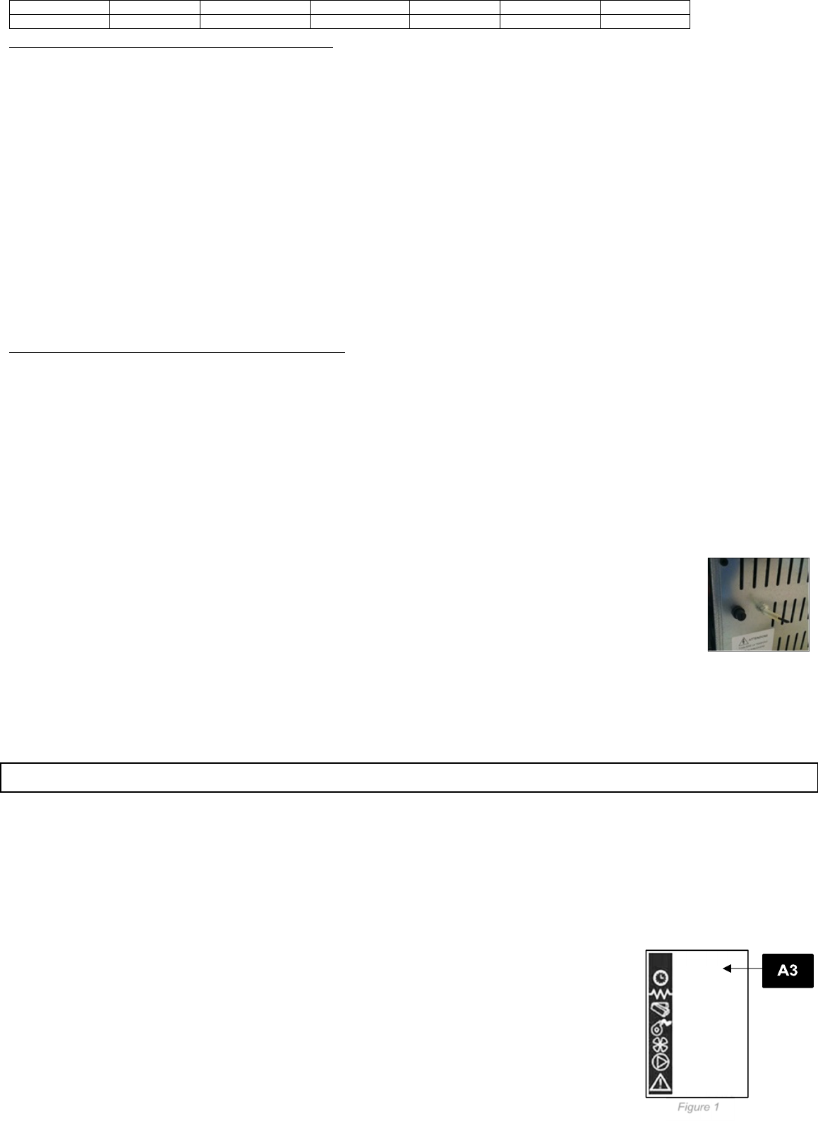
(A3) STATUS p. 3 F-2 and p. 17 figure 1
(A4) DIALOGUE
(A5) HEAT OUTPUT (A5)
Figure 1 p. 17 describes the meaning of the status indicators appearing on the display left side.
Programming: When the LED is lighted, it means that the corresponding component is active p. 17 figure 1
P. 3 F-3 describes the position of the messages visualised during working parameter programming or setting phase.
1. The input (B1) area shows the entered programming values
2. The menu level (B2) area displays the current menu. See chapter dedicated to menu p.17.
BUTTON (P1) - Temperature increase:
When in programming mode, use this button to modify/increase the selected menu value. When in WORK/OFF, use instead this button to increase the room
Gebruikershandleiding.com neemt misbruik van zijn services uitermate serieus. U kunt hieronder aangeven waarom deze vraag ongepast is. Wij controleren de vraag en zonodig wordt deze verwijderd.
Product:
Spelregels forum
Om tot zinvolle vragen te komen hanteren wij de volgende spelregels:
lees eerst de handleiding door;
controleer of uw vraag al eerder door iemand anders is gesteld;
probeer uw vraag zo duidelijk mogelijk te stellen;
heeft u een probleem en al geprobeerd om dit op te lossen, vermeld dit erbij aub;
heeft u een oplossing gekregen van een bezoeker dan horen wij dat graag in dit forum;
wilt u een reactie geven op een vraag of antwoord, gebruik dan niet dit formulier maar klik op de knop 'reageer op deze vraag';
uw vraag wordt direct op de website gezet; vermijd daarom persoonlijke gegevens in te vullen;
Belangrijk! Als er een antwoord wordt gegeven op uw vraag, dan is het voor de gever van het antwoord nuttig om te weten als u er wel (of niet) mee geholpen bent! Wij vragen u dus ook te reageren op een antwoord.
Belangrijk! Antwoorden worden ook per e-mail naar abonnees gestuurd. Laat uw emailadres achter op deze site, zodat u op de hoogte blijft. U krijgt dan ook andere vragen en antwoorden te zien.
Abonneren
Abonneer u voor het ontvangen van emails voor uw Eva Calor Dado bij:
nieuwe vragen en antwoorden
nieuwe handleidingen
U ontvangt een email met instructies om u voor één of beide opties in te schrijven.
Ontvang uw handleiding per email
Vul uw emailadres in en ontvang de handleiding van Eva Calor Dado in de taal/talen: Engels als bijlage per email.
De handleiding is 5,83 mb groot.
U ontvangt de handleiding per email binnen enkele minuten. Als u geen email heeft ontvangen, dan heeft u waarschijnlijk een verkeerd emailadres ingevuld of is uw mailbox te vol. Daarnaast kan het zijn dat uw internetprovider een maximum heeft aan de grootte per email. Omdat hier een handleiding wordt meegestuurd, kan het voorkomen dat de email groter is dan toegestaan bij uw provider.
Uw handleiding is per email verstuurd. Controleer uw email
Als u niet binnen een kwartier uw email met handleiding ontvangen heeft, kan het zijn dat u een verkeerd emailadres heeft ingevuld of dat uw emailprovider een maximum grootte per email heeft ingesteld die kleiner is dan de grootte van de handleiding.
Er is een email naar u verstuurd om uw inschrijving definitief te maken.
Controleer uw email en volg de aanwijzingen op om uw inschrijving definitief te maken
U heeft geen emailadres opgegeven
Als u de handleiding per email wilt ontvangen, vul dan een geldig emailadres in.
Uw vraag is op deze pagina toegevoegd
Wilt u een email ontvangen bij een antwoord en/of nieuwe vragen? Vul dan hier uw emailadres in.