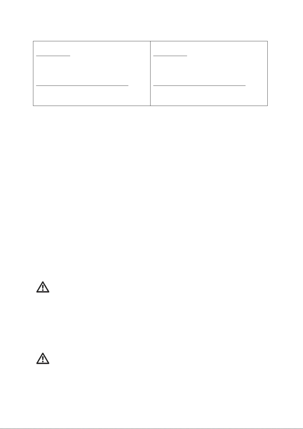
Table A
FRONT OF AXLE FITTING
(4,6mm2 cables)
Motor unit A: positive (+) cable to terminal 4
Motor unit A: negative (-) cable to terminal 3
Motor unit B: positive (+) cable to terminal 2
Motor unit B: negative (-) cable to terminal 1
Automatic engaging system (1,5mm2 cables):
Motor unit A: positive (+) cable to terminal d
Motor unit A: negative (-) cable to terminal c
Motor unit B: positive (+) cable to terminal b
Motor unit B: negative (-) cable to terminal a
Table B
REAR OF AXLE FITTING
(4,6mm2 cables)
Motor unit A: positive (+) cable to terminal 1
Motor unit A: negative (-) cable to terminal 2
Motor unit B: positive (+) cable to terminal 3
Motor unit B: negative (-) cable to terminal 4
Automatic engaging system (1,5mm2 cables):
Motor unit A: positive (+) cable to terminal b
Motor unit A: negative (-) cable to terminal a
Motor unit B: positive (+) cable to terminal d
Motor unit B: negative (-) cable to terminal c
Mark the motor cables for both motor units using the cable markers (30). The cables for the left and the right
motor should have the same length. Avoid any loops.
Remember to leave a small amount of slack cable near the motors to allow for their movement when the drive
rollers are engaged.
Route all the cables along the underside of the caravan floor, inside the supplied convoluted trunking (16) (this
will protect the electrical cables against sharp edges and dirt) and through the drilled hole.
Secure the cable trunking to the chassis or under body of the caravan by using the P-Clips (28) and screws (37).
Once the all cables are through the drilled hole next to the control unit, cut the cables, ensuring that they are
the same length. Remove approx. 5mm of the insulation from the ends. Fix the big spade fork connectors (26)
to the motor cables and the small spade fork connectors (27) to the automatic-engaging-cables by using
crimping pliers. A secure and good quality connection on each cable is essential.
Attach the spade fork connectors to the terminals on the control unit (see wiring diagram Fig. 6) and fix them
tightly by the screws. A safe and good quality connection on each cable is again essential.
Find a suitable place for the battery power isolation switch (33) which includes an external holder with hinged
cover. Important: The switch must be mounted onto the exterior body of the caravan and be easily
accessible from the outside of the caravan in case of any emergency. The switch must be mounted close
to the location of the battery in order to keep the length of the battery cables to a minimum.
Use the cardboard template to position the hole positions and the drill holes. Mount the switch and the housing
with the bolts, washers and nuts, and finally mount it on the caravan with stainless steel screws (37).
Route the positive (+) power cable (including fuse) from the battery to the battery power isolation switch and
then further to the control unit.
The electronic connections of the battery power isolation switch must be covered by the supplied rubber
isolation shells (35).
Route the negative (-) power cable directly to the control unit.
No cables may be routed over the control unit!
Again it is recommended to use the supplied trunking to protect the cables against sharp edges. Attach the
trunking with P-clips (28) and P-clip screws (37).
Cut the cables to an appropriate length and remove approx. 5mm of the insulation from the ends. Fix the
battery terminal connectors by using crimping pliers. Two types of battery terminal connector (24, 25) are
provided for use as appropriate. A secure and good quality connection on each cable is essential.
Connect the battery cables to the control unit: Attach the spade fork connectors to the positive (+) en negative
(-) terminal of the control box and fix them tightly by the screws.
Connect the battery cables to the existing battery terminals (red = positive, black = negative).
Caution! Make sure that you do not reverse the positive (+) and negative (-) connections.
Incorrect connection (reverse polarity) will result in damage to the control unit.
Connect the battery cables to the control unit.
Seal the 25mm hole in vehicle under body using plastic body sealant.