516209
81
Verklein
Vergroot
Pagina terug
1/92
Pagina verder
F
F
a
a
s
s
t
t
E
E
t
t
h
h
e
e
r
r
n
n
e
e
t
t
/
/
W
W
i
i
r
r
e
e
l
l
e
e
s
s
s
s
1
1
1
1
b
b
/
/
g
g
P
P
r
r
i
i
n
n
t
t
S
S
e
e
r
r
v
v
e
e
r
r
w
w
i
i
t
t
h
h
S
S
t
t
o
o
r
r
a
a
g
g
e
e
S
S
e
e
r
r
v
v
e
e
r
r
(
(
N
N
A
A
S
S
)
)
User’s Manual
Version: 1.0
(February, 2007)
COPYRIGHT
Copyright ©2007/2008 by this company. All rights reserved. No part of this
publication may be reproduced, transmitted, transcribed, stored in a retrieval
system, or translated into any language or computer language, in any form or
by any means, electronic, mechanical, magnetic, optical, chemical, manual or
otherwise, without the prior written permission of this company.
Federal Communication Commission
Interference Statement
This equipment has been tested and found to comply with the limits for a
Class B digital device, pursuant to Part 15 of FCC Rules. These limits are
designed to provide reasonable protection against harmful interference in a
residential installation. This equipment generates, uses, and can radiate radio
frequency energy and, if not installed and used in accordance with the
instructions, may cause harmful interference to radio communications.
However, there is no guarantee that interference will not occur in a particular
installation. If this equipment does cause harmful interference to radio or
television reception, which can be determined by turning the equipment off
and on, the user is encouraged to try to correct the interference by one or
more of the following measures:
1. Reorient or relocate the receiving antenna.
2. Increase the separation between the equipment and receiver.
3. Connect the equipment into an outlet on a circuit different from that
to which the receiver is connected.
4. Consult the dealer or an experienced radio technician for help.
FCC Caution
This equipment must be installed and operated in accordance with provided
instructions and a minimum 20 cm spacing must be provided between
computer mounted antenna and person’s body (excluding extremities of
hands, wrist and feet) during wireless modes of operation.
This device complies with Part 15 of the FCC Rules. Operation is subject to
the following two conditions: (1) this device may not cause harmful
interference, and (2) this device must accept any interference received,
including interference that may cause undesired operation.
Any changes or modifications not expressly approved by the party responsible
for compliance could void the authority to operate equipment.
Federal Communication Commission (FCC) Radiation Exposure
Statement
This equipment complies with FCC radiation exposure set forth for an
uncontrolled environment. In order to avoid the possibility of exceeding the
FCC radio frequency exposure limits, human proximity to the antenna shall
not be less than 20cm (8 inches) during normal operation.
The antenna(s) used for this transmitter must not be co-located or operating in
conjunction with any other antenna or transmitter.
R&TTE Compliance Statement
This equipment complies with all the requirements of DIRECTIVE 1999/5/EC
OF THE EUROPEAN PARLIAMENT AND THE COUNCIL of March 9, 1999 on
radio equipment and telecommunication terminal Equipment and the mutual
recognition of their conformity (R&TTE).
The R&TTE Directive repeals and replaces in the directive 98/13/EEC
(Telecommunications Terminal Equipment and Satellite Earth Station
Equipment) As of April 8, 2000.
Safety
This equipment is designed with the utmost care for the safety of those who
install and use it. However, special attention must be paid to the dangers of
electric shock and static electricity when working with electrical equipment. All
guidelines of this and of the computer manufacture must therefore be allowed
at all times to ensure the safe use of the equipment.
EU Countries Intended for Use
The ETSI version of this device is intended for home and office use in Austria,
Belgium, Denmark, Finland, France, Germany, Greece, Ireland, Italy,
Luxembourg, the Netherlands, Portugal, Spain, Sweden, and the United
Kingdom.
The ETSI version of this device is also authorized for use in EFTA member
states: Iceland, Liechtenstein, Norway, and Switzerland.
EU Countries Not intended for use
None.
Contents
1. Introduction......................................................................1
2. Product Package .............................................................2
3. Hardware Installation.......................................................3
4. Hardware Placement .......................................................4
4.1 Rear Panel .......................................................................... 4
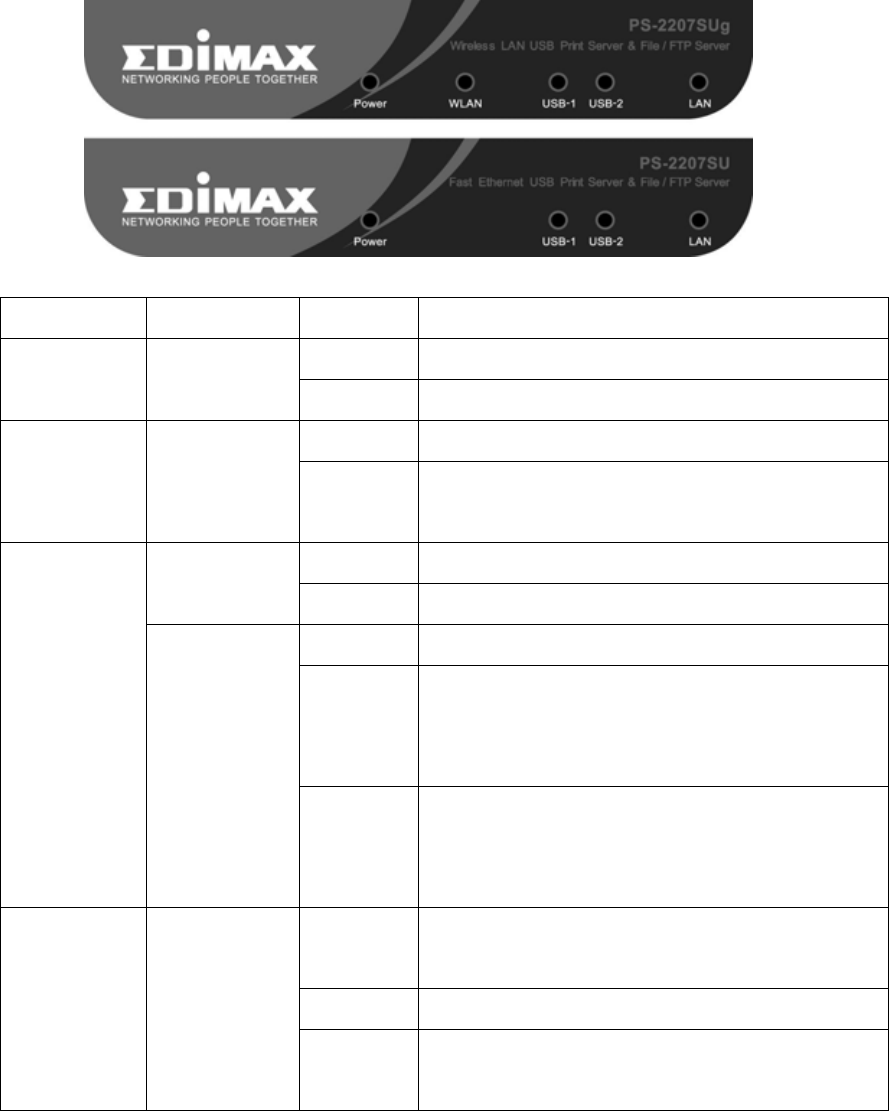
4.2 Front LEDs .......................................................................... 6
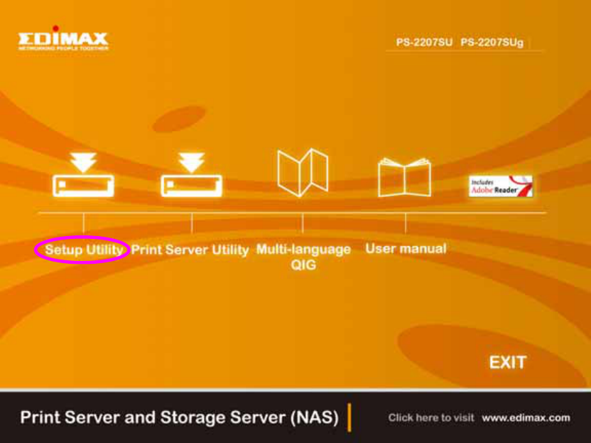
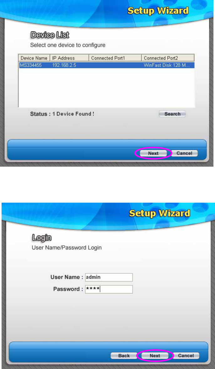
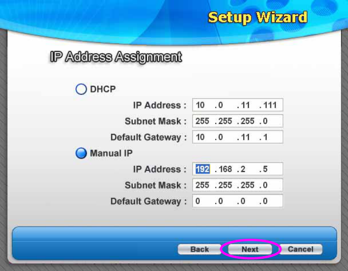
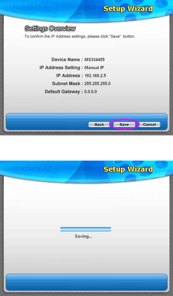
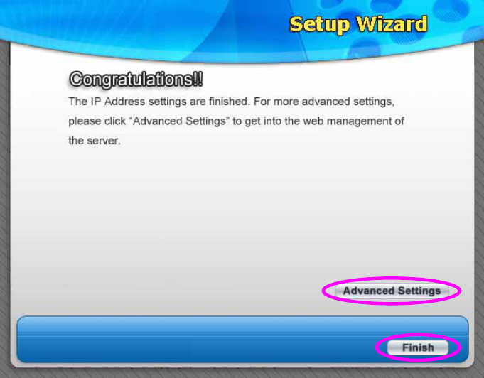
5. Setup Wizard ...................................................................7
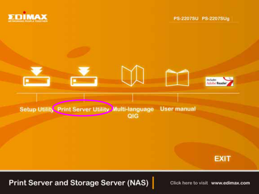
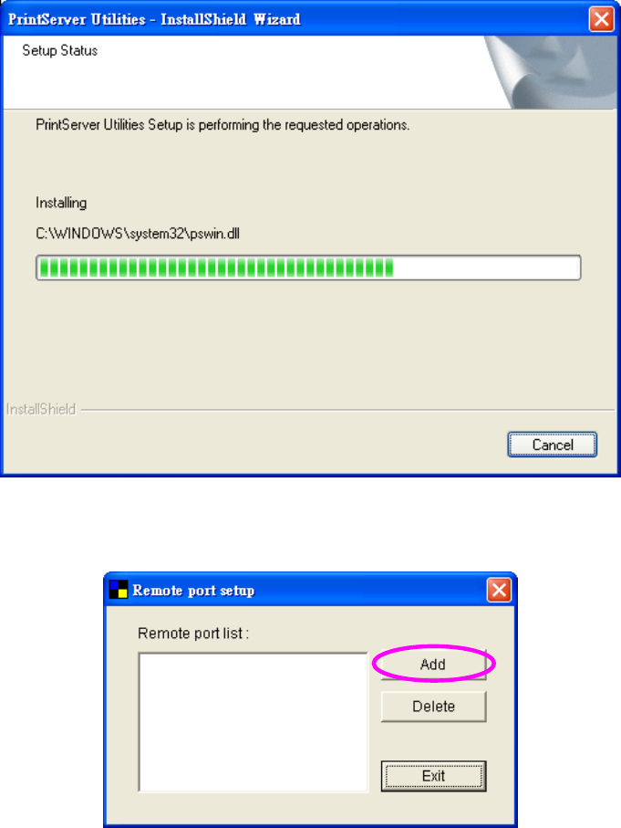
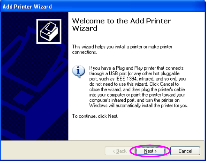
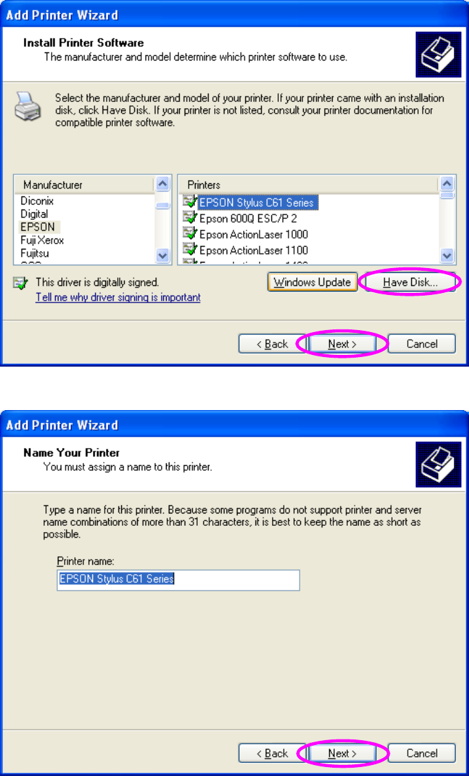
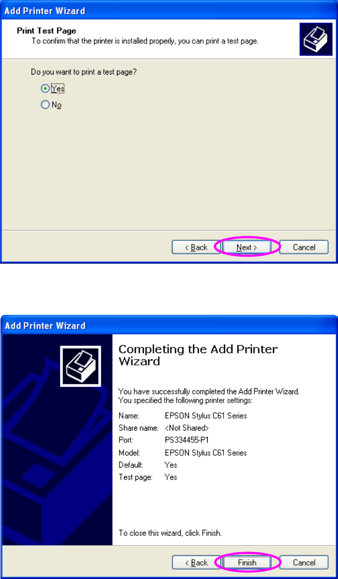
6. Print Server Installation..................................................12
7. FTP/File Server Configuration .......................................20
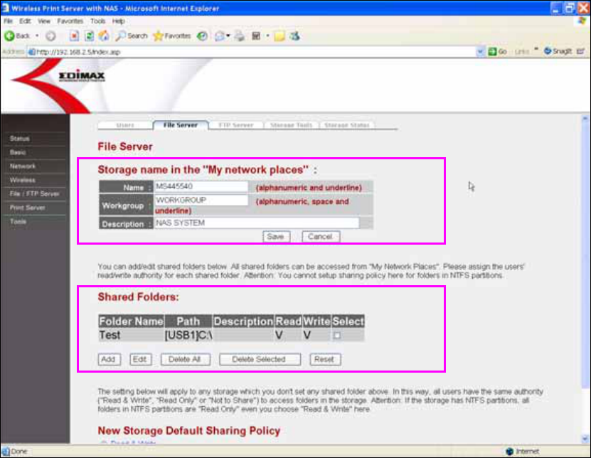
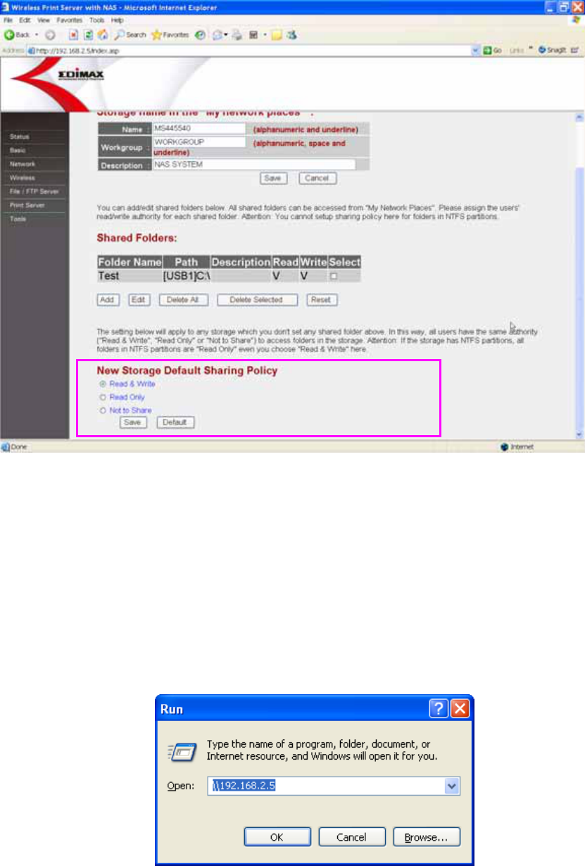
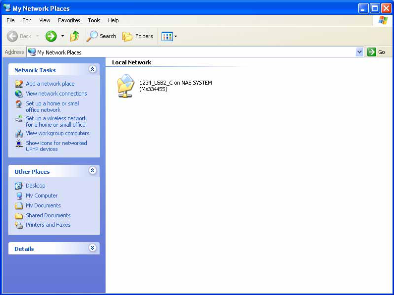
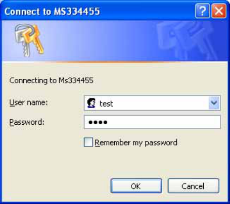
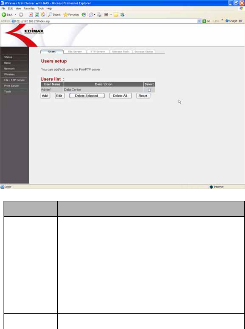
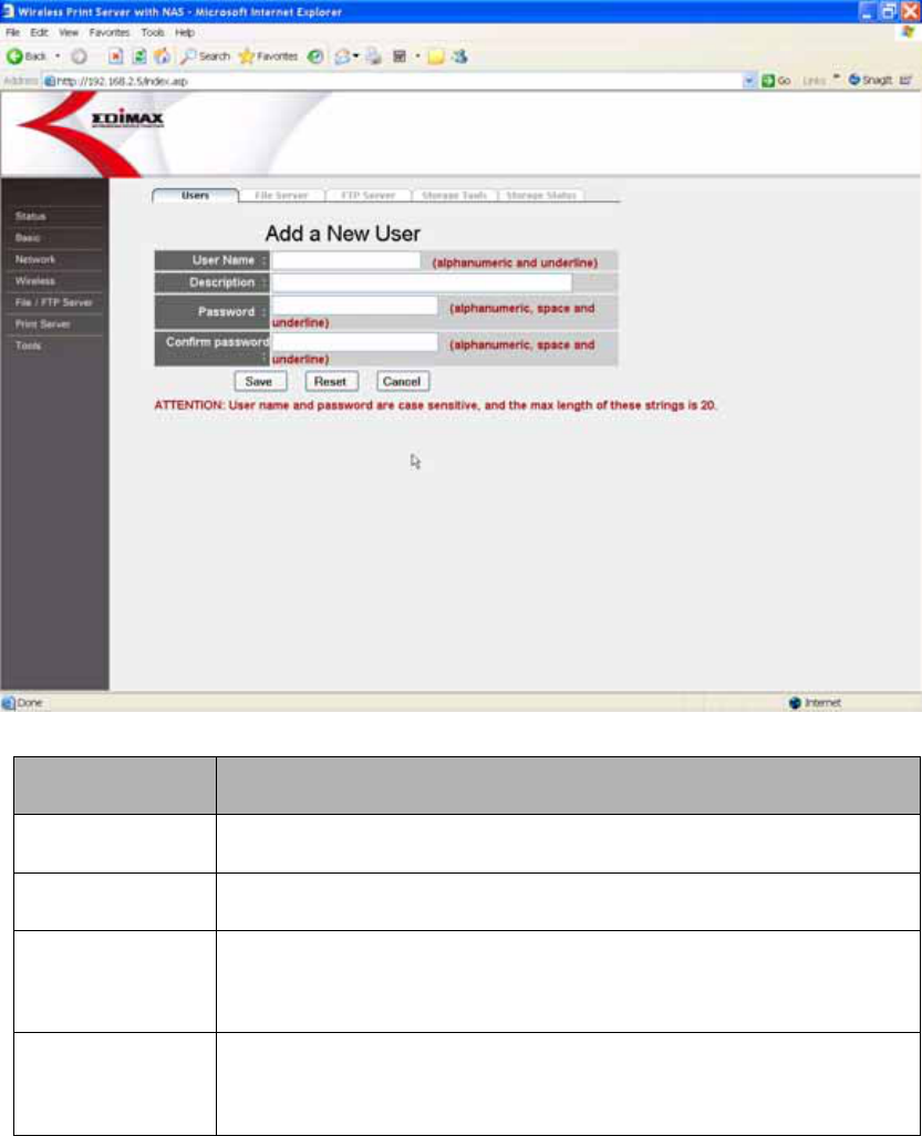
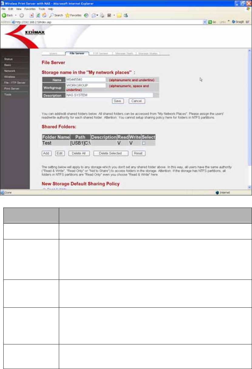
7.1 File Server......................................................................... 20
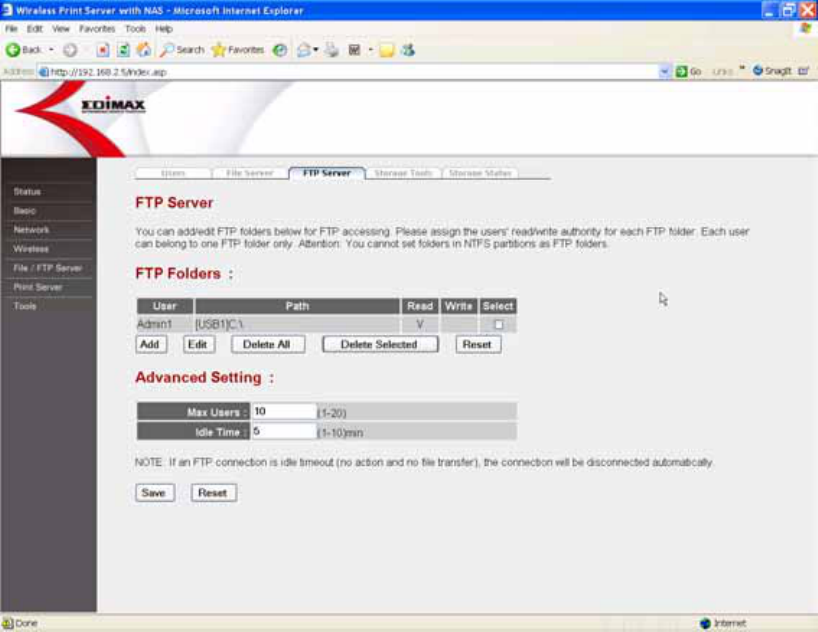
7.2 FTP Server ........................................................................ 26
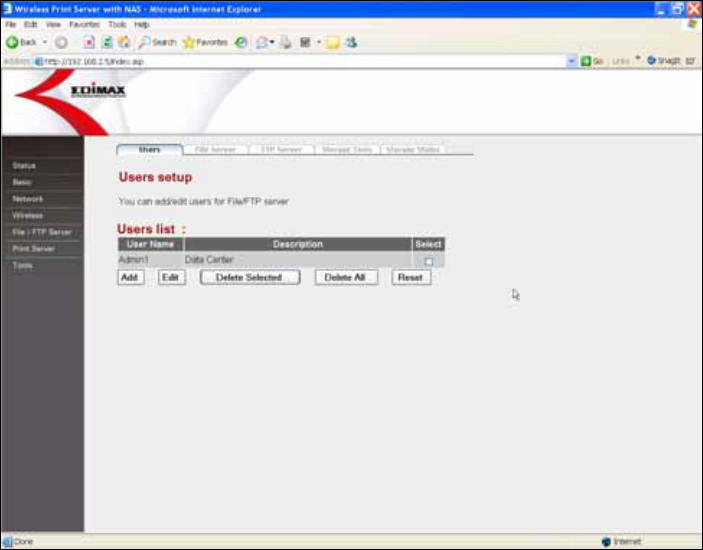
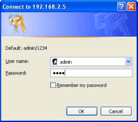
8. Web Management .........................................................26
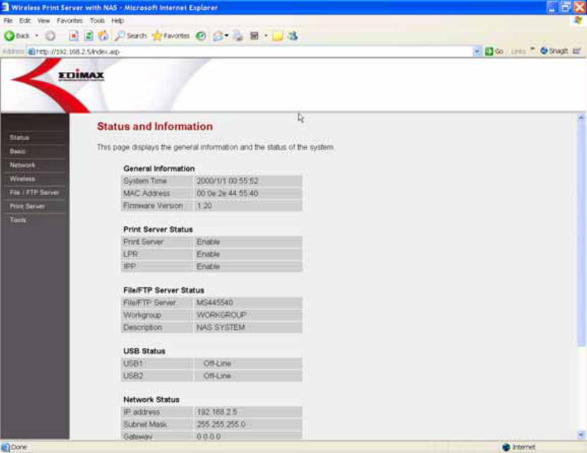
8.1 Status ................................................................................ 29
8.2 Basic..................................................................................30
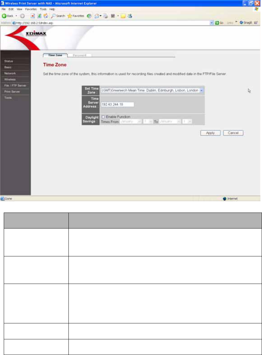
8.2.1 Time Zone.............................................................................30
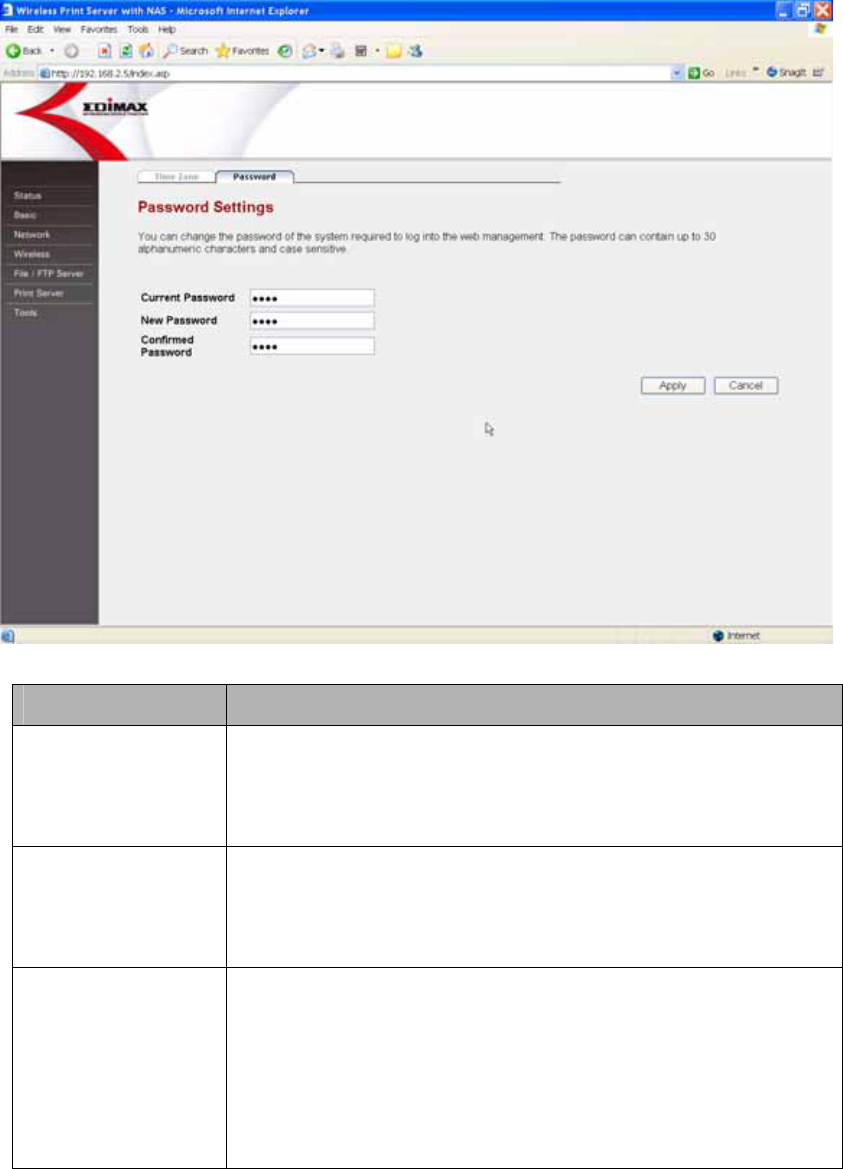
8.2.2 Password..............................................................................31
8.3 Network ............................................................................. 32
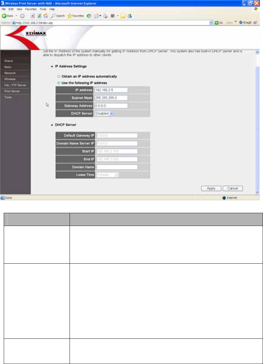
8.3.1 IP Address Settings...............................................................32
8.3.2 DHCP Server ........................................................................34
8.4 Wireless............................................................................. 36
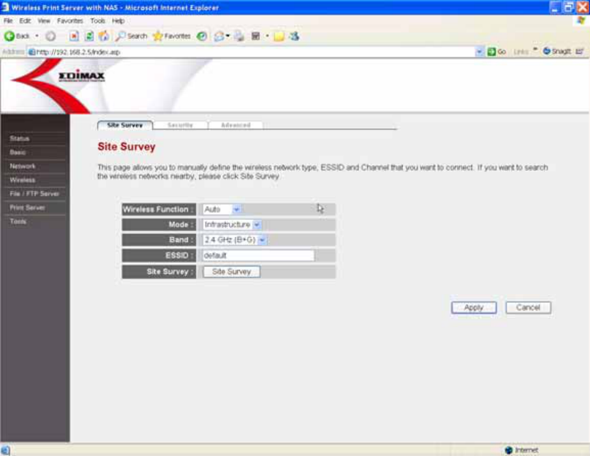
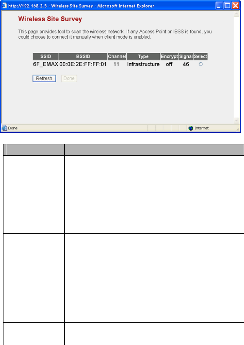
8.4.1 Site Survey ...........................................................................36
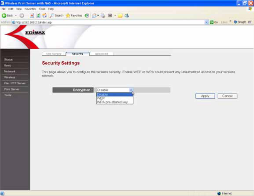
8.4.2 Security.................................................................................40
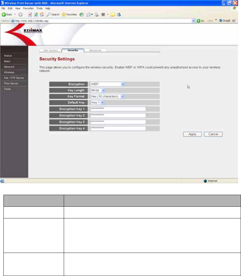
8.4.2.1 WEP...........................................................................41
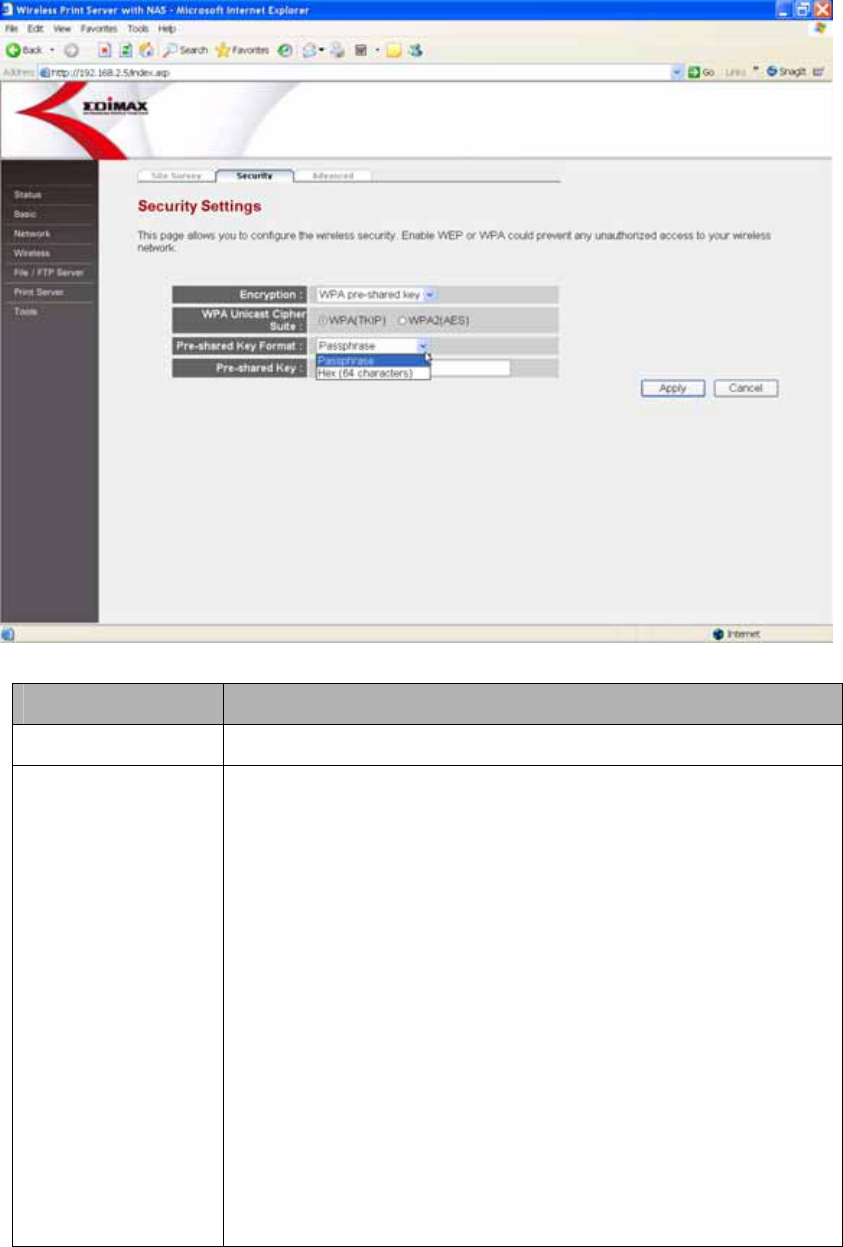
8.4.2.2 WPA-PSK...................................................................43
8.4.3 Advanced..............................................................................45
8.5 Print Server ....................................................................... 48
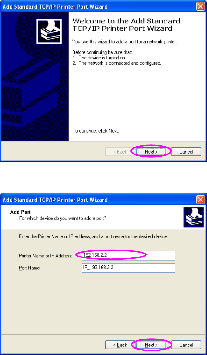
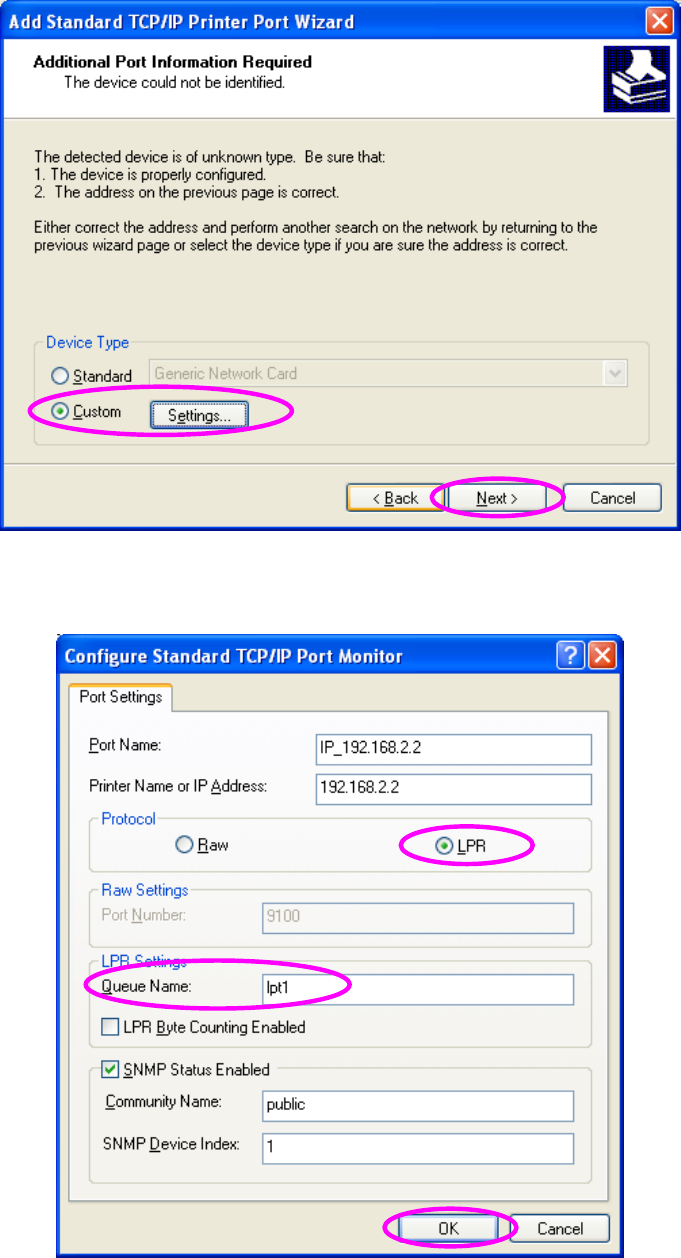
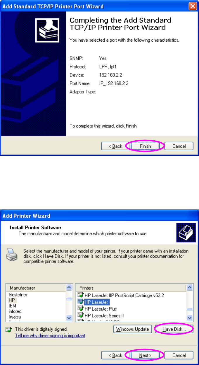
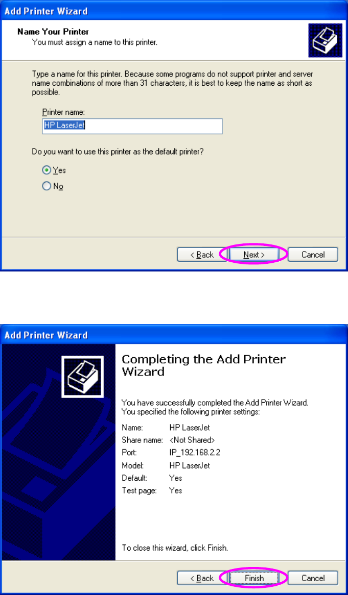
8.5.1 LPR Printing..........................................................................50
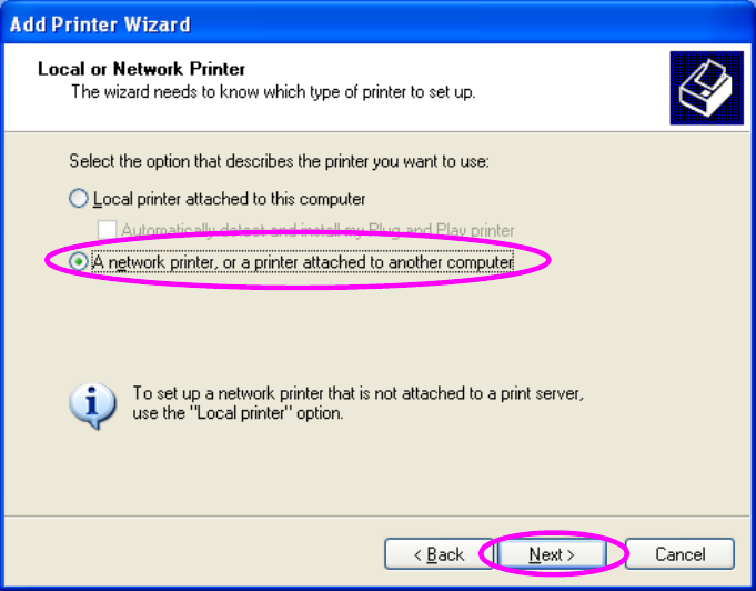
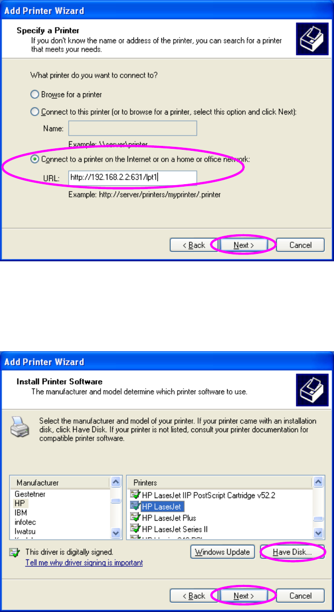
8.5.1.1 Windows 2000/XP/2003.............................................50
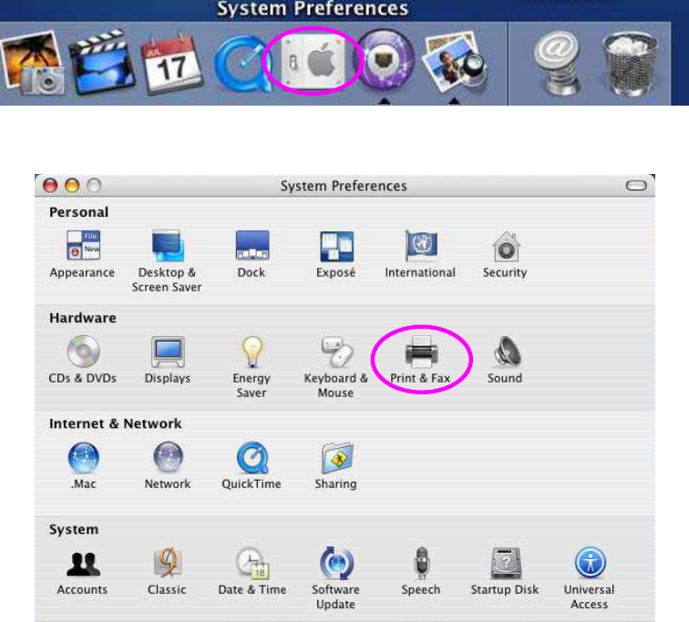
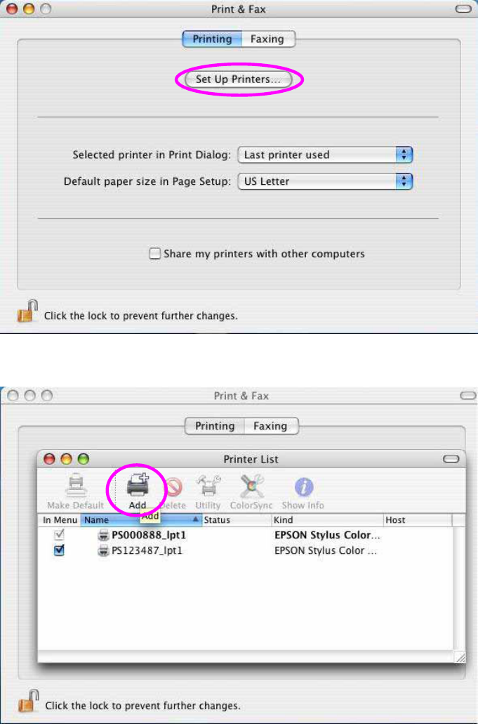
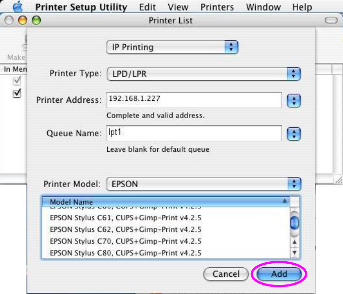
8.5.1.2 MAC OS.....................................................................56
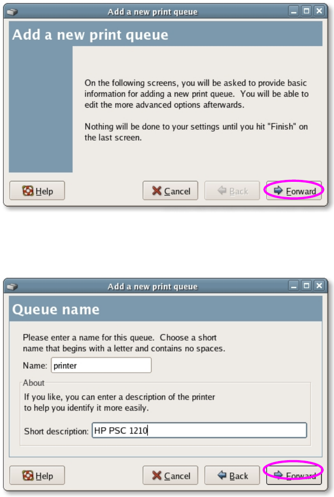
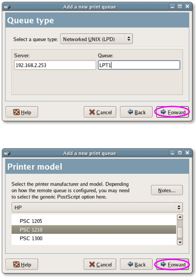
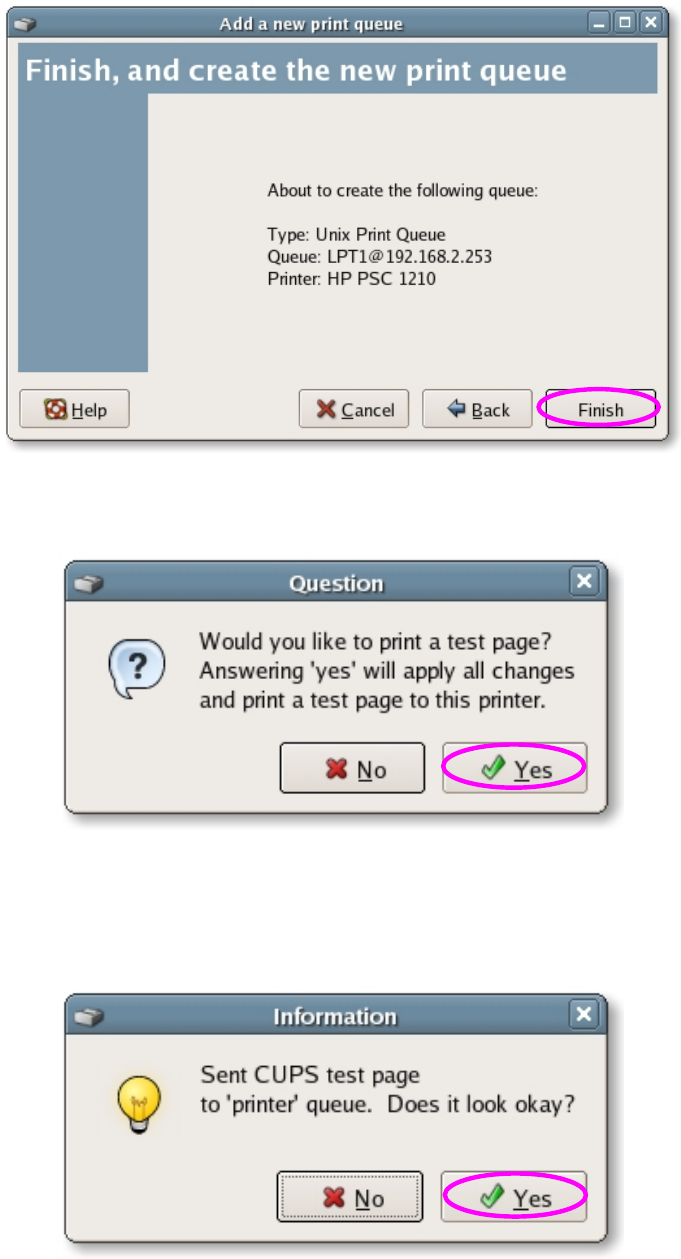
8.5.1.3 Linux/Unix ..................................................................61
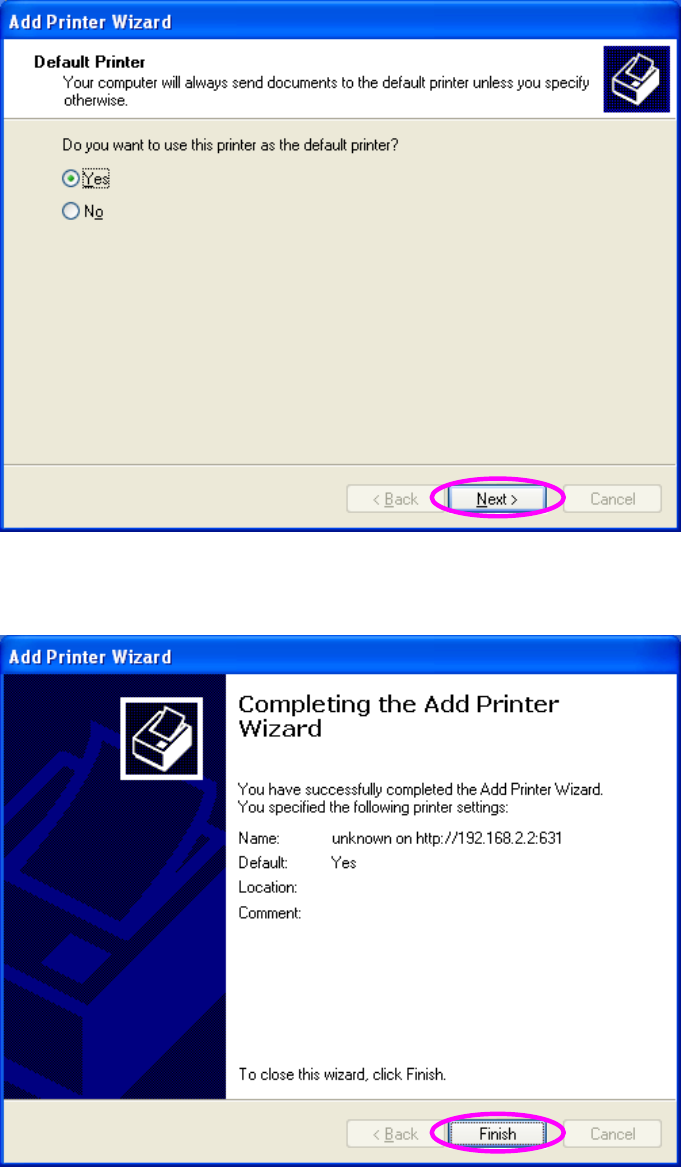
8.5.2 IPP Printing...........................................................................65
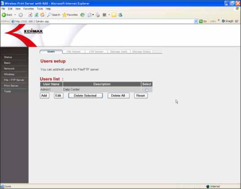
8.6 FTP/File Server ................................................................. 69
8.6.1 Users ....................................................................................70
8.6.2 File Server ............................................................................72
8.6.3 FTP Server............................................................................76
8.6.4 Storage Tools ........................................................................79
8.6.5 Storage Status.......................................................................82
8.7 Tools.................................................................................. 83
8.7.1 Configuration Tools ...............................................................83
8.7.2 Firmware...............................................................................84
8.7.3 Reset ....................................................................................85
1
1. Introduction
Thank you for purchasing and using our Print Server with Storage Server
(NAS) product. This product provides two USB 2.0 ports. User can connect
the USB mass storage or printer to each USB port. When the USB mass
storage is connected, the device can be a Storage Server (NAS, Network
Attached Storage) allowing user to share files in the storage. When the printer
is connected, the device can be a print server allowing user to share printer
through the network.
Main Features
Comply with IEEE 802.3, IEEE 802.3u Wired Ethernet and IEEE 802.11g/b
(2.4GHz) Wireless LAN standards.
Share USB Mass Storage or Printer to all PCs through Wired or Wireless
Network.
Compatible with all major operating systems (Windows 98SE/Me/2000/XP,
MAC OS and Unix/Linux).
Easy to configure through the Setup wizard and Web Management tool.
Print Server
Supports LPR, IPP and Raw printing protocols.
High compatibility with the popular brands of printers.
NAS
Share USB Hard Disk or Flash Drive through the network.
Support FAT16, FAT 32, Ext2, Ext3 and NTFS (Read Only for NTFS) file
systems.
Built-in Samba/FTP Server.
Support account management and user authorization for file folders.
Release USB storage through hardware buttons.
2
2. Product Package
This package contains the following components:
One Print Server with Storage Server (NAS)
One Dipole Antenna (PS-2207SUg only)
One Power Adapter
One Quick Installation Guide
One CD-ROM (Including all the software utilities, drivers and User’s
Manual)
3
3. Hardware Installation
Step 1. Connect the server to your LAN network
Connect the server to your PC, hub or switch by attached the Ethernet cable
to the LAN port of the server.
Step 2. Connect the USB devices to the USB ports of the server
You could connect the USB mass storage or printer to any one of two ports for
files or printer sharing.
Note 1: It is recommended to plug the external power to your USB mass
storage devices if the USB LED of the connected port is not lit.
Note 2: Please plug the USB mass storage dedicated to this server in the USB
port 1 for disk management such as Add/Delete Partitions or Format the disk. If
you just want to share the USB mass storage, you can plug the storage in USB
port 1 or 2.
Note3: USB Flash Disk has to be plugged to USB port 2.
Step3: Connect the power adapter to the server
You must use the power adapter shipped along with the server, do NOT use
any other power adapter from other sources.
4
4. Hardware Placement
4.1 Rear Panel
1) Power Jack
Please plug the power adapter attached with the server to the power jack.
2) Antenna Connector (PS-2207SUg only)
The antenna connector of the server is reverse SMA connector. It allows
you to connecting an external antenna with reverse SMA connector to the
server easily.
3) USB 1 and USB 2
The USB ports allow you to connect to printer or USB mass storage for
network sharing.
4) Release 2 and Release 1
The Release button is used to safely remove USB mass storage from your
server. Click the Release 1 and 2 buttons for over 5 seconds to remove
device connected in the USB port 1 and port 2 individually. The USB LED
of the USB port will be blinking after you have clicked Release button for
over 5 seconds. Please unplug the USB mass storage while the USB LED
is blinking. When the USB LED is turning unlighted, the release function is
cancelled.
Note1: If the release function is cancelled, the USB mass storage will be
reconnected by the server. Please wait a moment till the USB LED for the
USB port is turn on again.
5
Note 2: If you experience extreme problems or you forgot your password,
press the Release 1 for longer than 10 seconds and the server will reset
itself to the factory default settings (warning: your original configurations
will be replaced with the factory default settings)
5) Local Area Network (LAN)
The server’s LAN port is where you connect your hubs, switches or
routers.
6
4.2 Front LEDs
On the server’s front panel there are LED lights that inform you of the server’s
current status. Below is an explanation of each LED and its description.
LED Mode Status Description
On The device is ready Power
(Green)
Both
Off No power
Off The wireless mode is disabled.
WLAN Green
Blinking
The device is trying to connect to the AP or
station.
On Printing jobs are sending to the printer
Print Server
Off No printing jobs
On USB mass storage is ready to use
Off
No device is connected
Release is cancelled
Release is completed
USB Status
(Green)
FTP/File
Server
Blinking
The “Release” button is clicked for over 5
seconds. The USB LED is blinking to alert
user to unplug the USB mass storage.
On
The LAN cable is connected to the network
device such as hub or switch.
Off No network connection.
LAN
(Green)
Both
Blinking
Network traffic transferring or receiving
through the LAN port.
7
5. Setup Wizard
This Setup Wizard is for you to configure the server’s IP Address. This wizard
can be run in Windows 98SE/Me/2000/XP. The following procedures are
operated in Windows XP. (Procedures are similar for Windows
98SE/Me/2000.)
1. Insert the CD shipped along with the server into your CD-ROM drive. The
Autorun.exe program should be executed automatically. If not, run
Autorun.exe manually from “Autorun” folder in the CD.
2. The following screen will be displayed. Click “Setup Utility”.
8
3. The wizard will search for all the servers within the network and list the
connected device in each port of the servers. Please select the server you
want to configure and click “Next”.
4. Please enter user name and password to login the server. By default, the
user name is “Admin” and password is “1234”. Click “Next” to continue.
9
5. The wizard will try to determine your network settings automatically. If a
DHCP Server is present within the network, the wizard will automatically
obtain and configure the network settings assigned by the DHCP Server to
the server. The assigned IP Address will be shown in the IP Address fields.
If no DHCP Server is present within the network, please assign the
network settings of the server manually. Please click “Next” once you have
found appropriate network settings for the server. By default, the network
settings are as follows.
IP Address: 192.168.2.5
Subnet Mask: 255.255.255.0
10
6. Review the network settings of the server. If there is no problem, click
“Save” to save the settings and reboot the server.
7. The server is saving the settings and rebooting, please wait for a while.
11
8. The configuration is finished. For more settings, please click “Advanced
Settings” to get into the web management of the server. Or click “Finish” to
close the wizard.
12
6. Print Server Installation
This server provides a Print Server Setup tool for you to add the network port
of the server to your computer automatically. After you have added the
network port, you can run the standard “Add Printers” procedures in the
Windows to install the printer with the print server.
The program can be performed on Windows 98SE/Me/2000/XP/2003 with the
same user interface. Before installation, please confirm that your PC has
already connected to the network and installed TCP/IP network protocol.
Please follow the steps below to start installation.
1. Insert the CD shipped along with the server into your CD-ROM drive. The
Autorun.exe program should be executed automatically. If not, run
Autorun.exe manually from “Autorun” folder in the CD.
2. The following screen will be displayed. Click “Print Server Utility”.
13
3. The “PrintServer Utilities” window will be displayed. Click “Next”.
4. Click “Next” to install the utilities in the default folder or click “Browse” to
specify the destination folder where you would like to install the utilities.
14
5. The system will start to install the utilities automatically.
6. The “Remote Port Setup” is for you to add the network port of the print
server to your computer. Please click “Add”.
7. Enter the “Print Server Name” and the “IP Address” of the server and also
select the port number, then click “OK” to add the print server port to your
computer.
Print Server Name: It is the last 6-digit of MAC ID with prefix “PS”.
IP Address: By default, it is “192.168.2.5”.
Port: Designate the printer port name for each port. By default, it is “lpt1”
for USB port 1 and “lpt2” for USB port 2.
15
8. The network port of the print server is set completely. Click “Exit”.
9. Click “Finish” to complete the installation.
16
Add Printer
After adding a “Network Port” of the print server to your PC, you can follow the
procedure described below to add printer to the Windows. Note that following
“Add Printer” steps are running in Windows XP, the steps in other Operating
Systems are similar.
1. Click “Start”, and select “Printers and Faxes”.
2. Click “Add a Printer”.
3. The “Add Printer Wizard” is displayed. Click “Next”.
17
4. Select “Local printer attached to this computer” and make sure that
“Automatically detect and install my Plug and Play printer” is not selected.
Click “Next”.
5. Choose the suitable “Print Server Network Port” which was created by the
installation process and click “Next”.
18
6. Select the printer manufacturer and the printer model and click “Next”. If
your printer is not in the list, click “Have Disk…” to install the driver of the
printer. After installation, the printer model will be added to the list.
7. Name your printer and setup the default printer, click “Next”.
19
8. Choose to print the test page or not. It is recommended to print a test page.
Click “Next”.
9. You have added the printer to the PC successfully. The information of the
printer is displayed in the windows. Click “Finish”.
10. Now you can start to print from your PC to the print server.
20
7. FTP/File Server Configuration
The server provides FTP/File Server function, which let you share a USB
storage device to all PCs in your Intranet/Internet. It supports SAMBA protocol
in File Server, let you share files via Network Neighborhood. And also
supports FTP Server for your FTP clients to upload/download files from the
server.
7.1 File Server
To share the USB mass storage or USB Flash Disk from the server, please
follow the procedures below.
1. Open your Web Browser and enter the IP address of the server to logon to
the web management of the server. The default settings of the server are:
IP Address: 192.168.2.5
User Name: admin
Password: 1234
2. Set the users who are authorized to access to the USB storage device in
the “Users” menu of “FTP/File Server” page.
Click Add
Enter the user information, including User Name and Password.
21
3. Set the share folders of the USB storage device, which are allowed to
access by authorized users in the “Storage Server” menu of “FTP/File
Server” page.
Set the following information to identify your USB storage device on the
network.
Storage Name: By default the storage name is the last 6-digit of MAC
ID with prefixes “MS”.
Workgroup: The default workgroup is “WORKGROUP”.
Description: The device name displayed in “My Network Places”.
Follow the default settings, you will find a device “NAS System
(MS334455)” from workgroup computers in “My Network Places” of the
Windows.
Please assign the shared folders and the user’s read/write authority.
Folder Name: Enter the name for shared folder.
Path: Designated the shared folder path or enable to share all folders in
the storage.
Description: The comments or description for the shared folder.
User: Assign users with read/write authority for the shared folder.
Read/Write: Select “Read Only” or “Read/Write”.
Note: You can not set sharing policy here for folders in NTFS partitions.
22
If you want to set all users have the same authority to share the all
folders in the storage, please select “Read & Write”, “Read Only” or “Not
to Share” here.
Note1: If you have set shared folders and the user’s read/write authority,
the “New Storage Default Sharing Policy” you set here will not enable.
Note2: If the storage has NTFS partitions, all folders in NTFS partitions
are “Read Only” even you choose “Read & Write” here.
23
4. Access the share folder of the USB storage device.
Double click “My Network Places” in Windows. You will find the USB
storage device.
Note: If you cannot find the device in “My Network Places”, you can click
“Start” and select “Run….” Enter “\\IP Address of the server” to access
the device.
24
Double click the device to logon to the folder.
User Name: Please enter the user’s name who has been allowed to
access the folder.
Password: Please enter the users password.
Note1: In Windows, multiple connections to a server or shared resource
by the same user, using more than one user name, is not allowed. Please
make sure that you use one user name for one computer to access the
same shared resource.
Note2: If you cannot logon to the shared folder, it is recommended to
enter “Storage Name or IP Address of the server\User Name” (for
example: MS334455\test or 192.168.2.5\test) in the “User Name” field.
25
26
7.2 FTP Server
To set the USB mass storage or USB Flash Disk as FTP Server for your FTP
clients to upload/download files from the server, please follow the procedures
below.
1. Open your Web Browser and enter the IP address of the server to logon to
the web management of the server. The default settings of the server are:
IP Address: 192.168.2.5
User Name: admin
Password: 1234
2. Set the users who are authorized to access to the USB storage device in
the “Users” menu of “FTP/File Server” page.
Click Add
Enter the user information, including User Name and Password.
27
3. Set the shared folders of the USB storage device which are allowed to
access by authorized users in the “FTP Server” menu of “FTP/File Server”
page.
Please assign the shared folders and the users read/write authority.
User: Select the user who has the right to access the FTP Server.
Path: Designated the shared folder path.
Read/Write: Select “Read Only” or “Read/Write”.
Note: You can not set sharing policy here for folders in NTFS partitions.
4. Open your web browser and enter “ftp://IP Address of the Server”, for
example: ftp://192.168.2.5.
5. Enter user name and password to logon to the FTP Server.
28
8. Web Management
This server can be configured and managed on the Web. Through Local Area
Network, or even Internet, administrator can easily configure and manage the
server’s various main functions in browsers. Simply enter the server’s IP
address into your browser’s address field to start the configuration.
The default IP Address, User Name and Password settings of the server are
as follows.
IP Address: 192.168.2.5
User Name: Admin
Password: 1234
Note: Please make sure that your computer is in the same segment network of
the server or you cannot get into the web management of the server.
29
8.1 Status
The status of the server will be displayed here. You can find the information
including system time, firmware version, network settings and the USB port
status.
30
8.2 Basic
8.2.1 Time Zone
The Time Zone allows your server to refer the time configured here. This
information is used for recording files’ created and modified date in the
FTP/File server.
Parameter Description
Set Time Zone
Select the time zone of the country you are currently in.
The server will set its time based on your selection.
Time Server
Address
Set the time from a time server, the default time server is
“192.43.244.18”.
Daylight Savings
If your region is currently in DST, please check the
“Enable Function” and set the time period of Daylight
Savings.
Times From Select the beginning date of the Daylight Savings Time.
Times to Select the end date of the Daylight Savings Time.
Click <Apply> at the bottom of the screen to save the above configurations.
31
8.2.2 Password
You can change the password required to log into the server's web-based
management. By default, the password is “1234”.
Parameters Description
Current Password
Enter your current password for the remote
management administrator to login to your server. By
default, the password is “1234”.
New Password
Please enter your new password. The password can be
0 to 30 alphanumeric characters, and are case
sensitive.
Confirmed
Password
Enter your new password again for password
confirmation.
Note: If you forget your password, you have to reset the
server to the factory defaults by pressing the Release 1
button longer than 10 seconds.
Click <Apply> at the bottom of the screen to save the above configurations.
32
8.3 Network
8.3.1 IP Address Settings
You can configure the server to automatically get IP Address from DHCP
server or manually specify static IP Address. The IP Address of the server
must be set to have the same network segment within your network
environment or connected computer. If the network IP Address settings are
incorrect, then the server will not be able to communicate throughout the
network. For example, if your router/gateway/computer is using IP Address
192.168.2.1, then you need to give a unique IP Address to your server with IP
range 192.168.2.x (Please note: Above IP address setting is only an example,
please do not follow exactly!)
33
Parameters Description
Obtain an IP
Address
Automatically
If there is a DHCP Server within your network, please
select to obtain an IP Address from DHCP Server. Then
the DHCP server will assign a unique IP Address to
your server.
Use the following
IP Address
Password
If you want to set the server’s IP Address manually,
please select this option. You have to enter the IP
Address, Subnet Mask and Gateway Address for the
server.
IP Address
Enter the IP Address of the server. If your
router/gateway/computer is using IP Address
192.168.2.1, then you need to give a unique IP Address
to your server with IP range 192.168.2.x
Subnet Mask
Enter the same Subnet Mask as your
router/gateway/computer.
Gateway Address
Enter the same Gateway Address as your
router/gateway/computer.
DHCP Server
This server has a built-in DHCP Server; please select
“Enabled” to activate the function. By default, it is
disabled.
Click <Apply> at the bottom of the screen to save the above configurations.
34
8.3.2 DHCP Server
This server has a built-in DHCP Server. If the DHCP Server is enabled, it will
automatically give your LAN clients a unique IP Address, also include Default
Gateway and DNS Server IP Address if you have designated.
Parameters Description
Default Gateway
IP
A default gateway is a node (a router) on a network that
serves as an access point to another network. Please
enter the IP Address of the default gateway.
Domain Name
Server IP
A Domain Name System (DNS) server is like an index
of IP addresses and Web addresses. If you type a Web
address into your browser, such as “www.server.com”, a
DNS server will find that name in its index and the
matching IP address. Please enter the DNS Server IP
Address here.
Start IP
The Start IP is the first IP Address assigned to the LAN
client. By default, the “Start IP” is “192.168.2.100”.
Click <Apply> at the bottom of the screen to save the above configurations.
35
Parameters Description
End IP
The End IP is the last IP Address assigned to the LAN
client. By default, the “End IP” is “192.169.2.200
Domain Name You can specify a Domain Name for your LAN.
Lease Time
In the Lease Time setting you can specify the time
period that the DHCP Server lends an IP Address to
your LAN clients. The DHCP will change your LAN
client’s IP Address when this time threshold period is
terminated.
Click <Apply> at the bottom of the screen to save the above configurations.
36
8.4 Wireless (PS-2207Sug only)
If you want to use the server through wireless LAN, please set up the server
through Ethernet first and make sure your wireless LAN setting is correct.
After setting the wireless LAN, unplug the Ethernet cable and restart the
server, then you can start to use the server through wireless LAN. If the
wireless configuration does not work, please plug the Ethernet cable again,
restart the server and configure the server through Ethernet until the wireless
LAN settings are correct.
8.4.1 Site Survey
This page allows you to enable/disable the wireless function and set the
wireless networks that you want to connect. If you want to automatically
search and connect to the wireless networks nearby, please click “Site
Survey” button.
37
Parameters Description
Wireless
Function
You can select “Auto”, Enable” or “Disable” to manually
configure the wireless function.
Auto – “Auto” is the default setting of the server. At this
mode, the server will automatically decide to enable or
disable the wireless function. When the server starts up,
it will auto-detect if the LAN port is connected to an
active network by an Ethernet cable. If this is the case,
the server will run in Ethernet mode. If the server is not
connected to an active network by Ethernet cable, the
server will run in wireless LAN mode.
Users can plug the Ethernet cable to the server at the
first, after configuring the server features and wireless
settings; they can unplug the Ethernet cable to enable
the wireless connection. It makes the configuration
much easier without creating the wireless connection in
advance.
Enable – Enable wireless function only, the servers
wireless LAN will be always enabled and Ethernet will
be always disabled.
Disable – Disable the wireless function, the server’s
wireless LAN will be always disabled and Ethernet will
be always enabled.
Mode
InfrastructureThis operation mode requires the
presence of an 802.11 Access Point or Router. All
communication is done via the Access Point or Router.
Ad-Hoc – Select this mode if you want to connect to
other wireless stations in the Wireless LAN network
without through an Access Point or Router.
Click <Apply> at the bottom of the screen to save the above configurations.
38
Parameters Description
Band
2.4GHz (B)This server can be compatible with both
802.11g and 802.11b wireless devices. If there are only
802.11b wireless devices in the network, you can set
the server to this mode.
2.4GHz (G)This server can be compatible with both
802.11g and 802.11b wireless devices. If there are only
802.11g wireless devices in the network, you can set
the server to this mode.
2.4GHz (B+G) – If you have a mix of 802.11b and
802.11g wireless devices in your network, it is
recommended to set the server to this mode. This mode
is also the default setting.
ESSID
The ESSID (up to 32 printable ASCII characters) is the
unique name identified in a WLAN. The ID prevents the
unintentional merging of two co-located WLANs.
You may specify an ESSID for the server and then only
the device with the same ESSID can interconnect to the
server. By default, the ESSID of the server is “default”.
Channel
The radio channel used by the wireless LAN. All devices
in the same wireless LAN should use the same channel.
When you have set the wireless mode to Ad Hoc, you
have to select the channel that is used in the Ad Hoc
network.
Site Survey
Click “Site Survey” and then the server will scan all the
channels to find all the access points/routers/stations
within the accessible range of your server. You can then
connect to one of the networks you have selected.
Click <Apply> at the bottom of the screen to save the above configurations.
39
Site Survey Tool
From the “Site Survey”, all the networks nearby will be listed. You can select
the network you want to connect and click “Done”.
Parameters Description
SSID
The SSID (up to 32 printable ASCII characters) is the
unique name identified in a WLAN. The SSID name of
the access points/routers/stations nearby will be listed
here.
BSSID The MAC ID of the access point/router/station.
Channel
The radio channel used by the wireless LAN. All devices
in the same wireless LAN should use the same channel.
Type
Display the type of the network. If the network is an
Infrastructure network, it will show “Infrastructure”. If the
network is an Ad Hoc network, it will show “Ad Hoc”.
Encrypt
Display the security setting of the network. If “Off” is
displayed, it means that the network is no security
settings.
Signal
The signal strength of the network will be displayed
here. The higher signal strength, the better link quality.
Select
Click the radio button of the network which you want to
connect and click “Done” to connect to the network.
40
8.4.2 Security
This server supports 64/128-bit WEP data encryption that protects your
wireless network from eavesdropping. It also supports WPA-PSK and
WPA2-PSK security, which provide stronger security level for your wireless
network.
41
8.4.2.1 WEP
Parameters Description
Encryption Select “WEP” encryption type.
Key Length
You can select “64 bit” or “128 bit” length for the data
encryption. Longer key length can provide stronger
security but worth communication performance.
Key Format
You can select “Hexadecimal” or “ASCII” format for the
encryption key.
Click <Apply> at the bottom of the screen to save the above configurations.
42
Parameters Description
Default Key
Select the default key from the key1 to 4. The default
key will be used to encrypt the transmission data from
the server.
Note: The default key on the wireless device that you
want to connect and the server can have different
default WEP keys as long as the keys are in the same
order. In other words, the wireless device can use WEP
key 2 as its default key to transmit, while the server can
use WEP key 3 as its default key to transmit. The two
devices will communicate as long as the wireless
device's WEP key 2 is the same as the server's WEP
key 2, and the wireless device's WEP key 3 is the same
as the server's WEP key 3.
Encryption Key
1-4
Enter the four sets of keys; the key order should be the
same as the wireless device you want to connect.
64-bit – Input 10-digit Hex values (in the “A-F”, “a-f” and
“0-9” range) or 5-digit ASCII characters (including “a-z”
and “0-9”) as the encryption keys. For example:
“0123456aef“ or “test1”.
128-bit – Input 26-digit Hex values (in the “A-F”, “a-f”
and “0-9” range) or 13-digit ASCII characters (including
“a-z” and “0-9”) as the encryption keys. For example:
“01234567890123456789abcdef“ or “administrator”.
Click <Apply> at the bottom of the screen to save the above configurations.
43
8.4.2.2 WPA-PSK
Parameters Description
Encryption Select “WPA pre-shared key” encryption type.
WPA Unicast
Cipher Suite
WPA-PSK is suitable for home and small business. It
uses TKIP for data encryption. When “WPA-PSK” is
selected, please enter 8-64 characters as the
“Pre-Shared Key”.
WPA2-PSK is also for home and small business. The
difference between WPA-PSK and WPA2-PSK is that
WPA2-PSK provides data encryption via the AES. In
contrast, WPA-PSK uses Temporal Key Integrity
Protocol (TKIP). WPA2-PSK offers the highest level of
security available. When “WPA2-PSK” is selected,
please enter 8-64 characters as the “Pre-Shared Key”.
Click <Apply> at the bottom of the screen to save the above configurations.
44
Parameters Description
Pre-shared Key
Format
You can select “Passphrase” or “Hex (64 characters)”
format for the WPA pre-shared key.
Pre-shared Key
Enter 8 to 64 digits as you select “Passpharse” format
or 64 digits (in the “A-F”, “a-f” and “0-9” range) as you
select “Hex” format to be the key for the authentication
within the network.
Click <Apply> at the bottom of the screen to save the above configurations.
45
8.4.3 Advanced
You can set advanced wireless LAN parameters of this sever. The parameters
include Fragment Threshold, RTS Threshold, Data Rate, Preamble Type, etc.
It is recommended that do not change these parameters unless you know
what effect the changes will have on this server.
Parameters Description
Fragment
Threshold
Fragment Threshold specifies the maximum size of
packet during the fragmentation of data to be
transmitted. If you set this value too low, it will result in
bad performance. Enter a value from 256 to 2346.
RTS Threshold
When the packet size is smaller than the RTS threshold,
the server will not use the RTS/CTS mechanism to send
this packet. The range is from 0 to 2347.
Click <Apply> at the bottom of the screen to save the above configurations.
46
Parameters Description
Data Rate
There are several data rates including
Auto/1/2/5.5/11/6/9/12/18/24/36/48/54Mbps for you to
select. When the “Auto” is selected, the device will
choose the most suitable transmission rate
automatically.
Preamble Type
The preamble defines the length of the CRC block for
communication among wireless devices. There are two
modes including Long and Short Preamble. Therefore,
for an IEEE 802.11g network to be interoperable with
IEEE 802.11b clients, it must use larger preambles than
it would normally need.
CTS Protect
The RTS/CTS protection mechanism is needed to
ensure that all the devices can access the medium
when IEEE 802.11b and IEEE 802.11g devices are
co-existence in the same network. Especially, when
Hidden Node is existent. Hidden Node occurs when
different clients connected to the same access point
cannot see each other, decide that the channel is free,
and transmit at the same time. The frames collide when
they reach the access point and all of them are rejected.
When CTS protect is enabled, the throughput will be a
little lower but it will help to reduce the packet loss.
Select “Auto”, the server will automatically enable the
CTS protection mechanism when it is needed. Select
“Always”, the function will be always enabled. If you
don’t want to enable the function, please select “None”.
Click <Apply> at the bottom of the screen to save the above configurations.
47
Parameters Description
Turbo Mode
This sever supports specific ways to increase the data
transfer rate at a time; compress the data and decrease
the waiting time to send the next data to the Access
Point or Router, this feature (known as Turbo Mode)
enables higher throughput than IEEE 802.11g standard.
When the server is connecting to the Access Point or
Router with the same proprietary Turbo Mode feature,
the Turbo Mode will be enabled automatically without
any configuration.
WMM
This server supports WMM function. When you use the
devices such as Voice over Internet Protocol (VoIP)
phones, televisions, VCRs and MP3 players, IEEE
802.11e Quality of Service (QoS) (The Wi-Fi Alliance
defined WMM as a profile of the IEEE 802.11e)
extensions for 802.11 networks will help to define the
priorities of the data traffics by the data categories to
provide enhanced multimedia support.
When the server is connected to the Access Point or
Router with WMM function, you can enable the function
of the server.
Click <Apply> at the bottom of the screen to save the above configurations.
48
8.5 Print Server
The server supports print server function by default. It supports LPR/IPP
printing protocols. These two protocols allow users to connect to printers via
TCP/IP for printing sharing. By using LPR protocol, the computer with
Windows 98SE/Me/NT/2000/XP/2003, MAC OS 9.x above and Linux/Unix
operating systems can use the protocol to share printing in the network. By
using IPP protocol, you can share the printer to all the computers that can
access the server by IP Address in Windows 2000/XP/2003 operating
systems.
49
Parameters Description
Print Server
Features
Enable or disable the print server function. By default, it is
enabled.
IPP When the print server function is enabled, the IPP
protocol will be enabled as well. IPP (Internet Printing
Protocol) Printing provides a convenient way of remote
printing service by TCP/IP. The server can support IPP
printing in Windows 2000/XP/2003 by default. By using
the IPP printing, you can share the printer to all the PC’s
that can access the server by IP. You can even share
your printer to Internet users.
LPR When the print server function is enabled, the LPR
protocol will be enabled as well. LPR Printing (Line
Printer Remote technology) allows users to connect to
printers via TCP/IP for printing sharing. The computer
with Windows 98SE/Me/NT/2000/XP/2003, MAC OS 9.x
above and Linux/Unix operating systems can use the
protocol to share printing in the network.
Print Server
Name
The name of the print server. You can use this name to
identify the print server when you are searching for the
print server by the Windows utilities. By default, the print
server name is the last 6-digit of MAC ID with prefix “PS”.
Queue Name of
USB Port 1
The server has two USB 2.0 ports. If you connect a
printer to the USB port 1, you have to designate a printer
queue name to the port. Then you can use this name to
access the printer port. By default, the printer queue
name is “lpt1” for port 1.
Queue Name of
USB Port 2
The server has two USB 2.0 ports. If you connect a
printer to the USB port 2, you have to designate a printer
queue name to the port. Then you can use this name to
access the printer port. By default, the printer queue
name is “lpt2” for port 2.
Click <Apply> at the bottom of the screen to save the above configurations.
50
8.5.1 LPR Printing
LPR printing protocol is supported in Windows 98SE/Me/NT/2000/XP/2003,
MAC OS 9.x above and Linux/Unix. The following sections introduce the
standard LPR setup process in Windows 2000/XP/2003, MAC OS 9.x and
Linux/Unix.
Note: It is recommended that running the Print Server Setup Tool in Windows
operating system when you want to install the print server. Please refer to
Chapter 6.
8.5.1.1 Windows 2000/XP/2003
To configure the LPR setting in Windows 2000/XP/2003, please follow the
steps below.
1. Click “Start”, choose “Settings” and select “Printers and Faxes”.
2. Click “Add a Printer”.
3. The “Add Printer Wizard” is displayed. Click “Next”.
51
4. Select “Local Printer attached to this computer” and click “Next”.
5. Choose “Create a new port” and “Standard TCP/IP Port”. Click “Next”.
52
6. Please make sure that the print server and the printer have turned on and
connected to the network correctly before you continue. Click “Next”.
7. Enter the IP Address of the print server in the “Printer Name or IP
Address”. Click “Next”.
53
8. Select “Custom” and click “Settings”. When you have finished the settings
at step 9, click “Next” to continue.
9. Select “LPR” and enter “lpt1” for printer attached in USB Port 1 or “lpt2” for
printer attached in USB Port 2 in the “Queue Name”, click “OK”.
54
10. Click “Finish”.
11. Select a suitable printer manufacturer and the printer model and click
“Next”. If your printer is not in the list, click “Have Disk…” to install the
driver of the printer. After installation, the printer model will be added to the
list.
55
12. Choose to set the print whether as a default printer or not. Click “Next”.
13. You have added the network printer to the PC successfully. The
information of the printer is displayed in the windows. Click “Finish”.
56
8.5.1.2 MAC OS
LPR Printing (Line Printer Remote technology) allows Macintosh computers to
connect to printers via TCP/IP. LPR Printing can be set up on any Macintosh
with version 9.x above.
MAC 10.4.x
To enable LPR Printing in Macintosh 10.4.x, please follow the procedures
below.
1. Open Print and Fax from the System Preferences.
2. With the Printing tab selected, click the “Add” button.
3. When the Printer Browser opens, select “IP Printer”.
4. In the “IP Printer” screen, please configure as below.
Protocol: Select Line Printer Daemon - LPD as the Protocol.
IP Address: Set the address to the server’s IP Address, for example:
192.168.2.5.
Queue: Set the queue name to lpt1 or lpt2.
Name: You can designate a name for the printer.
Location: You can enter the location of the printer.
Printer: Select the printer model that is attached to the server.
5. Click “Add” to complete the printer installation.
57
MAC 10.3.x
To enable LPR Printing in Macintosh 10.3.x, please follow the procedures
below.
1. In the Desktop, click “System Preferences”.
2. Click “Print & Fax”.
58
3. From the “Print & Fax” screen, click “Set Up Printers…”.
4. Click “Add” to add the new server through TCP/IP.
59
5. Enter the “Printer Type”, “Printer Address” and “Queue Name” and select
the “Printer Model” to setup the server. Click “Add” to continue.
Printer Type: LPD/LPR
Printer Address: Input the IP Address of the server
Queue Name: The queue name of the server is “lpt1” or “lpt2”.
Printer Model: Select the Printer Model that is attached to the server.
60
6. The server is installed completely. You can see it in the “Printer List”.
7. You can print a file to check whether the server is installed successfully.
61
8.5.1.3 Linux/Unix
The server is available for TCP/IP printing by Unix/Linux LPD (Line Printer
Daemon) protocol. This section explains how to set the server with the LPD
protocol in the Unix/Linux system. The following procedures are running in the
Fedora Core 4 system.
1. Select “Printing” from “System Settings”.
2. Click “New” to add the printer with the server.
62
3. Click “Forward”.
4. Set the printer queue name and the short description of the printer and
click “Forward”.
5. In the following screen, please configure as below. Then click “Forward” to
continue.
Select a queue type: Select “Network Unix (LPD)” as the queue type.
Server: Enter the IP Address of the server, for example: 192.168.2.253.
Queue: Set the queue name to lpt1 or lpt2.
63
6. Select the printer manufacturer and model and click “Forward”.
64
7. Please review the settings. If the settings are no problem, click “Finish”
8. To print a test page and apply all the settings, please click “Yes”.
9. If the test page is printed without problem, please click “Yes”. If it is failed
to print, please click “No” to go back to “Printer configuration - fedora”
screen and configure again.
65
8.5.2 IPP Printing
The server can support IPP printing in Windows 2000/XP/2003 by default. By
using the IPP printing, you can share the printer to all the PC’s that can
access the print server by IP. You can even share your printer to Internet
users.
Please perform Window’s standard Add New Printer procedure.
1. Click “Start”, choose “Settings” and select “Printers and Faxes”.
2. Click “Add a Printer”.
3. The “Add Printer Wizard” is displayed. Click “Next”.
66
4. Select “A network printer, or a printer attached to another computer”. Click
“Next”.
5. Select “Connect to a printer on the Internet or on a home or office network”
and enter the URL of server. The URL format is “http://IP Address of the
Server:631/Queue Name”. The IP Address should be the server’s IP
Address. The number 631 is IPP standard port number. Queue Name is
the queue name of the USB port that your printer is connected to. The
default queue name is “lpt1” for printer attached to USB Port 1 and “lpt2”
for printer attached to USB Port 2. One example of the URL is
http://192.168.2.2:631/lpt1. After entering the URL of the server, click
“Next”.
67
6. Select a suitable printer manufacturer and the printer model and click
“Next”. If your printer is not in the list, click “Have Disk…” to install the
driver of the printer. After installation, the printer model will be added to the
list.
68
7. Choose to set the print whether as a default printer or not. Click “Next”.
8. You have added the network printer to the PC successfully. The
information of the printer is displayed in the windows. Click “Finish”.
69
8.6 FTP/File Server
The server provides FTP/File Server function which let you share a USB
storage device to all PCs in your Intranet/Internet. It supports SAMBA protocol
in File Server, let you share files via Network Neighborhood. And also
supports FTP Server for your FTP clients to upload/download files from the
server.
When you start to use the FTP/File server, please read the following
information carefully.
1. This server supports USB mass storage with FAT16/32, EXT2, EXT3 and
NTFS file systems. This server can support “Read Only” when you use the
partition with NTFS file system.
2. The maximum file size of a single file is less than 2GB when using a
partition with FAT16/32 file system due to operating system limitation,
whereas for a partition with EXT2/3 file system, the file size is up to 4GB.
3. The maximum number of users you are able to set for sharing FTP/File
server is 32.
4. The maximum users that reserve the connection (such as open and edit
the files directly through the server) to the FTP or File Server concurrently
are 10 users.
70
8.6.1 Users
This page allows you to add/edit/delete users for FTP/File server.
Parameters Description
Add
Click “Add” and fill the information in the “Add a New User”
page to add a new user for FTP/File server.
Edit
You can select any user in Users list and click “Edit” to
modify the profile.
Delete Selected
Click “Delete Selected” to delete the selected users in
Users list.
Delete All Click “Delete All” to delete all the users in Users list.
Reset Click “Reset” to reset selection in Users list.
71
Add/Edit Users
Parameters Description
User Name Enter the user name of this user.
Description Enter the description for this user.
Password
Set the password for the user to logon to the USB mass
storage.
Confirm
Password
Re-type the password of this user for confirmation.
Click <Save> at the bottom of the screen to save the above configurations.
Note: The max number of users you are able to set for sharing FTP/File server
is 32.
72
8.6.2 File Server
You can add/edit the File Server name, shared folders and sharing policies for
sharing files via “My Network Places”.
Parameters Description
Name The File Server name that shows in “My Network Places”.
Workgroup
The workgroup that the server will be joined in “My
Network Places”. By default, the workgroup is
“WORKGROUP”.
Description
A brief description for this File Server. This string will be
shown at the detailed information in “My Network Places”.
Add
Click “Add” and fill the information of the “Add/Edit
Shared Folder” page to add a new shared folder for File
server.
Edit
Select any shared folder in Shared Folders list and click
“Edit” to modify its setting.
73
Parameters Description
Delete All
Click “Delete All” to delete all the shared folders in Shared
Folders list.
Delete
Selected
Click “Delete Selected” to delete the selected shared
folders in Shared Folders list.
Reset Click “Reset” to reset selection in Shared Folders list.
New Storage
Default Sharing
Policy
You can set a default sharing policy (Read & Write, Read
Only or Not to Share) to any USB storage which you don’t
set any shared folder. All users will have the same
authority to share all folders in the storage.
Note1: If you have set shared folders and the user’s
read/write authority, the “New Storage Default Sharing
Policy” you set here will not enable.
Note2: If the storage has NTFS partitions, all folders in
NTFS partitions are “Read Only” even you choose “Read &
Write” here.
74
Add/Edit Shared Folder
Parameters Description
Folder Name Define the shared folder name.
Shared Folder’s
Path
Click “Browse” to open the explorer window to select the
shared folder path or click “Share all folders in storage” to
share the whole storage.
Users
Here you can assign some users with read/write authority
for this shared folder. Select the users in “System Users”
and click “Add” to add into “Share Users”. Click “Add All” to
add all users. Select the users in “Share Users” and click
“Delete” to remove the selected users. Click “Delete All” to
remove all users.
Click <Save> at the bottom of the screen to save the above configurations.
81

Hulp nodig? Stel uw vraag in het forum

Spelregels

Misbruik melden

Gebruikershandleiding.com neemt misbruik van zijn services uitermate serieus. U kunt hieronder aangeven waarom deze vraag ongepast is. Wij controleren de vraag en zonodig wordt deze verwijderd.

Product:

Bijvoorbeeld antisemitische inhoud, racistische inhoud, of materiaal dat gewelddadige fysieke handelingen tot gevolg kan hebben.

Bijvoorbeeld een creditcardnummer, een persoonlijk identificatienummer, of een geheim adres. E-mailadressen en volledige namen worden niet als privégegevens beschouwd.

Spelregels forum

Om tot zinvolle vragen te komen hanteren wij de volgende spelregels:

Belangrijk! Als er een antwoord wordt gegeven op uw vraag, dan is het voor de gever van het antwoord nuttig om te weten als u er wel (of niet) mee geholpen bent! Wij vragen u dus ook te reageren op een antwoord.

Belangrijk! Antwoorden worden ook per e-mail naar abonnees gestuurd. Laat uw emailadres achter op deze site, zodat u op de hoogte blijft. U krijgt dan ook andere vragen en antwoorden te zien.

Abonneren

Abonneer u voor het ontvangen van emails voor uw Edimax PS-2207SUg bij:


U ontvangt een email met instructies om u voor één of beide opties in te schrijven.


Ontvang uw handleiding per email

Vul uw emailadres in en ontvang de handleiding van Edimax PS-2207SUg in de taal/talen: Engels als bijlage per email.

De handleiding is 2,09 mb groot.


U ontvangt de handleiding per email binnen enkele minuten. Als u geen email heeft ontvangen, dan heeft u waarschijnlijk een verkeerd emailadres ingevuld of is uw mailbox te vol. Daarnaast kan het zijn dat uw internetprovider een maximum heeft aan de grootte per email. Omdat hier een handleiding wordt meegestuurd, kan het voorkomen dat de email groter is dan toegestaan bij uw provider.

Stel vragen via chat aan uw handleiding

Stel uw vraag over deze PDF

Uw handleiding is per email verstuurd. Controleer uw email

Als u niet binnen een kwartier uw email met handleiding ontvangen heeft, kan het zijn dat u een verkeerd emailadres heeft ingevuld of dat uw emailprovider een maximum grootte per email heeft ingesteld die kleiner is dan de grootte van de handleiding.

Er is een email naar u verstuurd om uw inschrijving definitief te maken.

Controleer uw email en volg de aanwijzingen op om uw inschrijving definitief te maken

U heeft geen emailadres opgegeven

Als u de handleiding per email wilt ontvangen, vul dan een geldig emailadres in.

Uw vraag is op deze pagina toegevoegd

Wilt u een email ontvangen bij een antwoord en/of nieuwe vragen? Vul dan hier uw emailadres in.


Info