613236
9
Verklein
Vergroot
Pagina terug
1/56
Pagina verder
667
Special Sewing Machine
Instruction manual
Postfach 17 03 51, D-33703 Bielefeld • Potsdamer Straße 190, D-33719 Bielefeld
Tel: +49 (0) 521 / 9 25-00 • Fax: +49 (0) 521 / 9 25 24 35 • www.duerkopp-adler.com
Ausgabe / Edition:
12/2011
Änderungsindex
Rev. index: 00.0 Printed in Federal Republic of Germany
Teile-Nr./Part.-No.:
0791 667741
All Rights Reserved.
Property of Dürkopp Adler and copyright protected. Any use of this content, or part thereof, is subject to prior writ-
ten approval by Dürkopp Adler.
Copyright © Dürkopp Adler - 2011
Contents Page
Preface and General Safety Instructions
Part 1: Operating Instructions Class 667 – Original Operating Instructions
(Edition 12/2011)
1 General safety............................................................................................................................................. 1
2 Product description.................................................................................................................................... 3
2.1 Product description ..................................................................................................................................... 3
2.2 Proper Use, Designated use ........................................................................................................................ 3
2.3 Specifications .............................................................................................................................................. 3
2.4 Optional equipment ..................................................................................................................................... 5
3 Operation..................................................................................................................................................... 7
3.1 Threading the needle thread ....................................................................................................................... 7
3.2 Adjusting the needle-thread tension ........................................................................................................... 8
3.2.1 Function of the main thread tension and the supplementary thread tension in relation to the sewing foot
lift for subclass 667-180312 and 667-180322 ............................................................................................. 9
3.2.2 Function of supplementary thread tension in relation to the sewing foot lift and the Speedomat for
subclass 667-180312 and 667-180332........................................................................................................ 10
3.3 Opening the thread tension ......................................................................................................................... 11
3.4 Turning the supplementary thread tension on and off for subclasses 667-180312 and 667-180332 ........ 11
3.5 Adjusting the thread regulator ..................................................................................................................... 12
3.6 Winding on the hook thread ........................................................................................................................ 13
3.7 Changing the hook-thread bobbin .............................................................................................................. 14
3.8 Setting the hook thread tension .................................................................................................................. 15
3.9 Changing the needle ................................................................................................................................... 16
3.10 Lifting the sewing foot ................................................................................................................................. 17
3.11 Locking the sewing feet in an elevated position ......................................................................................... 18
3.12 Sewing foot pressure ................................................................................................................................... 18
3.13 Sewing-foot stroke ...................................................................................................................................... 19
3.14 Adjusting the stitch length ........................................................................................................................... 21
3.15 Key pad on the machine arm ...................................................................................................................... 22
3.16 Sewing with machines using the Efka DC1550/DA321G positioning drive ................................................ 24
4 Maintenance................................................................................................................................................ 27
4.1 Cleaning and inspection .............................................................................................................................. 27
4.2 Oil lubrication ............................................................................................................................................... 29
1 General safety
This instruction manual is intended to help familiarize the user with the
machine and to enable correct utilisation.
The instruction manual contains important information on how to operate the
machine safely, correctly and economically. Observation of the instructions
eliminates danger, reduces costs for repair and downtime, and increases the
reliability and service life of the machine.
The instruction manual is intended to complement existing national accident
prevention and environment protection regulations.
The instruction manual should always be available where the machine/sewing
unit is being used.
The instruction manual must be read and applied by any person authorised
to work on the machine/sewing unit. This means:
Operation, including equipping, troubleshooting during the work cycle,
removing of fabric waste,
Service (maintenance, inspection, repair) and/or
Transport
The user must ensure that only authorised persons work with the machine.
The user is required to check the machine at least once per shift for visible
damage and defects, and to report any changes which impair safety
immediately (including operating performance).
The company using the machine must ensure it is only operated in perfect
working order.
As a matter of principle, no safety equipment is to be removed or disabled.
If it is necessary to remove any safety equipment for preparation, repair, or
maintenance work, the safety equipment must be reinstalled immediately
upon completion of said work.
The manufacturer does not assume any liability for damages resulting from
unauthorized modification of the machine.
Observe all of the safety signs and hazard warnings on the machine/unit! The
yellow-and-black striped sections designate permanent hazard areas which
are associated with, for example, risk of crushing, cutting, shearing or
collision.
In addition to the information contained in this instruction manual you should
also observe the applicable general safety and accident prevention
regulations.
General safety precautions
Non-observance of the following safety precautions can result in bodily
injury or damage to the machine.
1. The machine should only be commissioned after reading the associated
operating manual and it should only be operated by persons who have
received the corresponding training.
2. Before starting to use the machine you should also read the safety
precautions specified by the motor manufacturer.
3. The machine should only be used for the purpose intended and with the
safety devices in place. Observe all of the applicable safety regulations.
4. The machine must be disconnected from the power supply by switching
off the master switch or disconnecting the mains plug when exchanging
sewing appliances (such as the needle, sewing foot, needle plate, feed
dog and bobbin), when threading, when leaving the workplace
unattended or when conducting service work.
5. Daily servicing procedures should only be conducted by appropriately
trained persons.
6. Repairs and special maintenance work should only be conducted by
specialist personnel or by persons who have received the corresponding
training.
7. When conducting service or repair work on pneumatic systems the
machine must be disconnected from the compressed air supply (max. 7
- 10 bar). Before disconnecting the machine the maintenance unit is to be
depressurised. An exception to this rule is only permitted for adjustments
and functional checks which are conducted by appropriately trained,
specialist personnel.
8. Work on the electrical equipment should only be conducted by
electricians or appropriately trained personnel.
9. Working on live parts and equipment is not permitted, except as specified
in regulations DIN VDE 0105.
10. Conversions or modifications made to the machine should only be
conducted in compliance with all of the applicable safety regulations.
11. Only those replacement parts approved by us are to be used for repairs.
12. Commissioning of the upper part is prohibited until such time as the entire
sewing unit complies with the provisions of the EC directives.
13. The connecting cable must be equipped with a country-specific mains
plug. The associated work must be conducted by an appropriately trained
specialist (also refer to point 8).
These symbols designate safety
precautions which must be observed at all
times.
Risk of injury!
Please also observe the general safety
precautions.
3
2 Product description
2.1 Product description
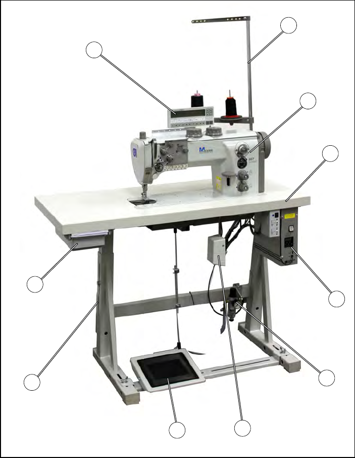
The Dürkopp Adler 667 is a special sewing machine for first-class single-
needle decorative seams in light to medium-heavy material.
It is a single-needle flatbed double-backstitch machine with lower
conveyor, needle transport and alternating upper foot conveyor.
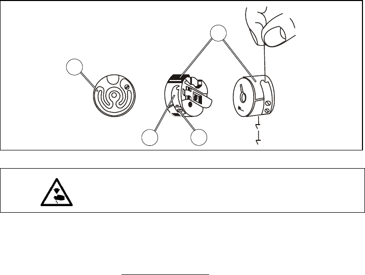
A safety coupling prevents the shuttle from being displaced or damaged
if the thread jams in the shuttle track.
Large horizontal shuttle or oversized shuttle.
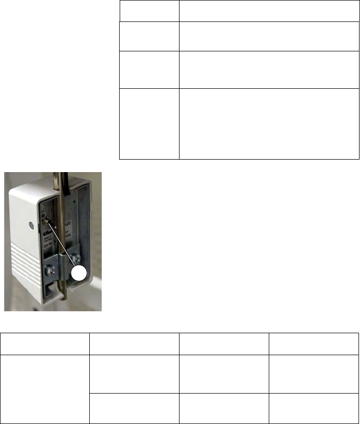
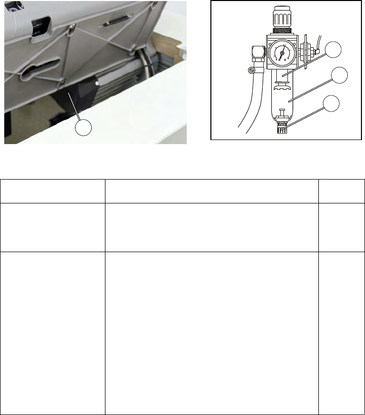
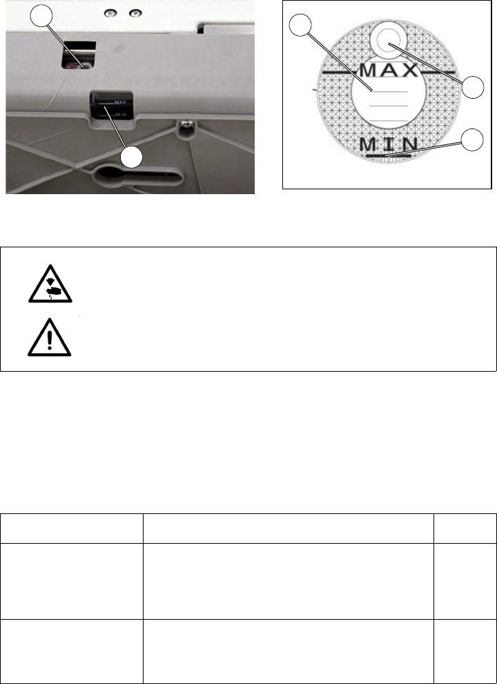
Automatic wick lubrication with viewing windows for the oil level.
Integrated bobbin winder.
2.2 Proper Use, Designated use
The 667 is a sewing machine designed for sewing light to medium-heavy
material. Such material generally consists of textile fibres, but can also
include leather. It is used in the clothing industry and for domestic and vehicle
upholstery.
This special sewing machine can also be used to produce so-called technical
s
eams. In this case, however, the operator must assess the possible dangers
which may arise (with which DÜRKOPP ADLER AG would be happy to
assist), since such applications are, on the one hand, relatively unusual and,
on the other, so varied that no single set of criteria can cover them all. The
outcome of this assessment may require appropriate safety measures to be
implemented.
Generally-speaking only dry material should be sewn with this machine. The
ma
terial should be no thicker than 10 mm when compressed by the lowered
sewing feet. The material should not contain any hard objects; if it does, the
machine should only be operated with eye protection. No such eye protection
can currently be provided.
The seam is generally produced with textile-fibre sewing thread of gauge up
to
15/3 NeB (cotton), 15/3 Nm (synthetic) or 15/4 Nm (covering yarn). Before
using any other thread the possible dangers arising must be assessed and
appropriate safety measures implemented if necessary.
This special sewing machine should only b
e set up and operated in dry, well-
maintained premises. If the sewing machine is used in premises which are not
dry and well-maintained,
it may be necessary to implement further precautions (which should be
ag
reed in advance - see EN 60204-31:1999).
As manufacturers of industrial sewing machines, we proceed on the
assumption that personnel who
work with our products will have received
training that is at least sufficient to acquaint them with all of the normal
operations and with any hazards that these may involve.
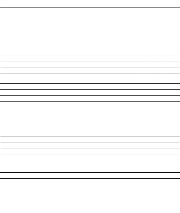
2.3 Specifications
Noise: Workplace-related emission value in accordance with DIN EN ISO 10821
667 LC = _dB (A)
Stitch length: _ mm, Sewing foot strok
e: ___ mm, Stitch rate: ____ rpm
4
2.3.1 Technical data for subclasses
Subclasses
667-180010
667-180030
667-180112
667-180132
667-180312
667-180332
Type of stitch Backstitch 301
Looper type horizontal, XL large, bobbin Ø 26 mm X X X
Looper type horizontal, XL oversized, bobbin Ø 32 mm X X X
Electromagnetic thread trimmer X X X X
Electropneumatic seam bartacking and sewing foot lift X X X X
Switchable thread tension XX
2 stitch lengths, can be switched electropneumatically X X
2 stroke heights with knee switch, can be switched elec-
tropneumatically
XX
Integrated sewing light XX
Number of needles 1
Needle system 134-35
Max. needle size [Nm] (depending on sewing mechanism) 80-
150
100-
170
80-
150
100-
170
80-
150
100-
170
Max. thread thickness [Nm] 80/3-
15/3
80/3-
10/3
80/3-
15/3
80/3-
10/3
80/3-
15/3
80/3-
10/3
Looper thickness [Nm] 100/
3-20/
3
100/
3-15/
3
100/
3-20/
3
100/
3-15/
3
100/
3-20/
3
100/
3-15/
3
Stitch length forwards/backwards [mm] 9 / 9
Max. stitch rate [rpm] 3000
Speed at factory setting [rpm] 3000
Max. sewing-foot stroke: [mm] 9
Max. height of lifted sewing feet [mm] 20
Operating pressure [bar] 6 6 6 6
Air consumption [NL] 0.7 0.7 0.7 0.7
Dimensions [mm] length / width / height (with attached
Efka DC 1550)
630/ 255/ 420(630/ 290/ 420)
Weight [kg](with attached Efka DC 1550) 50(54)
Rated voltage [V/Hz] depending on motor package
Rated voltage at factory setting [V/Hz] depending on motor package
Power rating [kVA] depending on motor package
5
2.4 Optional equipment
For the sewing machine 667 the following optional equipment is available:
2.5 Stands
Order no. Optional equipment Subclasses
667-180010
667-180030
667-180112
667-180132
667-180312
667-180332
9780 000108 WE-8 maintenance unit for optional pneumatic equipment XXXXXX
0797 003031 Pneumatic connection pack. For connecting stands to the main-
tenance unit
XXXXXX
0867 490010 Control panel angle X X
o
ooo
9822 510003 Halogen sewing light for sewing machine head XXXXXX
9880 867100 Sewing light mounting kit XXXXXX
0798 500088 Sewing light transformer XXXXXX
9880 867103 Diode sewing light (one diode) XXXXXX
9880 867102 Integrated sewing light XXXXoo
9850 001089 Power supply unit for integrated and diode sewing light XXXXoo
9850 867001 PCB for oil monitoring X X o o
0867 590014 Electropneumatic needle cooler, from above XXXX
0687 590984 Mounting kit FK, thread clamp with thread wiper function XXXX
0367 595124 Mechanical sewing foot lift with pedal X X
0687 590364 Pneumatic sewing foot lift (DC 1550) X X
0687 590464 Manual seam tacking o o X X o o
N800 080001Right edge guide, with roller, can be raised XXXXXX
N800 080004 Combined roller and straight guide, right, can be raised, height-
adjustable
XXXXXX
N800 080021Right edge guide, can be raised XXXXXX
N800 080022Guide, for attachment to the base plate XXXXXX
9805 791113 USB memory stick for data transfer with the Efka control unit
DA321G
XXXXXX
Order no.
Subclasses
667-180010
667-180030
667-180112
667-180132
667-180312
667-180332
MG55 400464MG55-3 stand set. Table plate: 1060 x 500 mm with pedal XXXXXX
6
7
3 Operation
3.1 Threading the needle thread
Place the thread reel on the thread stand and guide the needle
thread through the unwinder arm.
The unwinder arm must be in a vertical position above the thread
reels.
Thread in the thread through threading guides 1 and 2.
Wind the thread clockwise around the pre-tensioner 3.
Wind the thread counter-clockwise around the supplementary ten-
sioner 4.
Wind the thread clockwise around the main tensioner 5.
Pull the thread underneath the thread take-up spring 6 and pass it
through the guide 10 and thread regulator 11, up to the thread lever
12.
Insert the thread through the thread lever 12 and the threading
guides 9, 8 and 7 on the needle bar.
Thread the thread into the needle eye.
Caution: Risk of injury!
Switch off the main switch!
The needle thread should only be threaded when the sewing machine is
switched off.
Fig. 1 Fig
. 2
1
2
3
4
5
7
8
10
11
6
9
12
8
3.2 Adjusting the needle-thread tension
Fig. 3 Fig. 4
Fig. a: Correct thread interlacing in the centre of the mate-
rial
Fig. b:
Needle-thread tension too strong
or
hook-thread tension too
weak
Fig. c:
Needle-thread tension too strong
or
hook-thread tension too
weak
1
2
3
4
5
9
Pre-tension
When the main tensioner 2 and supplementary tensioner 3 are open the
needle thread must be under slight residual tension. This residual tension is
produced by the pre-tensioner 1.
The pre-tensioner 1 simultaneously affects the length of the end of the
se
vered needle thread (the starting thread for the next seam).
Basic setting:
T
urn adjusting knob 4 until its front is flush with bolt 5.
Shorter starting thread:
T
urn adjusting knob 4 clockwise.
Longer starting thread:
T
urn adjusting knob 4 counter-clockwise.
Main tension
The main tensioner 2 should be set to the minimum possible tension.
The cross-over point of the thread should be in the centre of the material.
When using thin material, excessive thread tension can cause unwanted
ga
thering and thread breakage.
Adjust the main tensioner 2 so that an even stitch pattern is produced.
I
ncrease tension - turn the adjusting knob clockwise.
Decrease tension - turn the adjusting knob counter-clockwise.
Supplementary tension
The supplementary tensioner 3 can be switched in to effect a rapid change in
ne
edle-thread tension during operation e.g. with thickened seams.
Set the supplementary tensioner 3 to be lower than the main tensioner 2.
3.2.1 Function of the main thread tension and the supplementary thread tension in rela-
tion to the sewing foot lift for subclass 667-180312 and 667-180322
Button 1 (see chapter 3.15) on the machine's keypad can be used to activate
or deactivate the supplementa
ry thread tension at any time. Parameter F-299
must be set to "1" for this.
1 = Thread tensioner mechanically opened
0 = Thread tensioner me
chanically closed
If the supplementary thread tensioner is open, the status of the sewing foot lift does not change.
If the machine is turned off, the supplementary thread tension remains at its previously set state.
Sewing foot lift in the seam Sewing foot lift afterthread
trimming
Parameter
Setting
Main
th
read
tensioner
Supple-
mentary
th
read
tensioner
Main thread
te
nsioner
Supplemen-
tary thread
tensioner
F-196=0
F-196=1
F-196=2
F-196=3
0
1
0
1
0
1
0
1
0
0
1
1
0
0
1
1
10
3.2.2 Function of supplementary thread tension in relation to the sewing foot lift and the
Speedomat for subclass 667-180312 and 667-180332
Button 1 (see chapter 3.15) on the machine's keypad can be used to activate
or deactivate the supplementary thread tension at any time. Parameter F-255
must
be set to "7" for this to work.
(*) When the max. stroke adjustment is switched on via the knee switch
and the HP-speed of parameter F-117 is reached by the "Speedomat", the
su
pplementary thread tension is switched on automatically.
0 = Supplementary thread tension mechanically closed
1 = Supplementary thread tension mechanically opened
If the supplementary thread tensioner is closed, it remains closed during the stroke adjustment.
If the machine is turned off, the supplementary thread tension remains at its previously set state.
Basic adjustment in the control box for automatic stepwise speed reduction
(Speedomat) by the adjusting knob for the height of the alternating feeding
stroke.
Parameter 188
Step 01-21 entire Speedomat range
Step 01-10 maximum permitted speed, parameterF-111 = 3000 rpm
Step 11-18 linear stepwise reduction of the maximum speed
(
Speedomat)
Step 19-21 maximum permitted speed, parameter F-117 = 1800 rpm
Parameter
Ad
justment
Max. stroke adjustment
via knee switch
Stroke adjusted by the
adjusting knob when
reaching the HP speed
of parameter F-117
(Speedomat)
F-197 = 0
F-197 = 1
F-197 = 2
F-197 = 3
1
0
1 (*)
0
1
1
0
0
11
3.3 Opening the thread tension
Subclasses
667-180010, 667-180030
When lifting the sewing feet with the knee switch, main and supplementary
ten
sion are automatically opened.
Subclasses
667
-180112, 667-180132, 667-180312, 667-180332
The thread tension is automatically opened when trimming the thread.
3.4 Turning the supplementary thread tension on and off for subclasses 667-180312 and
667-180332
Fig. 5
The supplementary tension can be switched on and off with lever 1.
Switching on
Pus
h the handle 2 of lever 1 to the left.
Switching off
Pu
sh the handle 2 of lever 1 to the right.
12
3.5 Adjusting the thread regulator
Fig. 6
The thread regulator 1 controls the quantity of needle thread required for
stit
ch formation. The thread regulator must be precisely adjusted for an
optimum result.
With correct setting the needle-thread loop must slide with low tension over
the t
hickest point of the hook.
Loosen screw 2.
Ad
just the position of thread regulator 1: thread regulator to the left
= more thread; thread regulator to the right = less thread
Tighten screw 2.
Adjustment information:
If the maximum quantity of thread is required, the thread-tensioning spring 3
must
be pulled upwards approx. 0.5 mm from its lower limit position. This is
the case when the needle-thread loop passes the maximum hook diameter.
Caution: Risk of injury!
Switch off the main switch.
The thread regulator may only be adjusted with the sewing machine switched
off.
1
3
2
13
3.6 Winding on the hook thread
Put the thread reel on the thread stand and lead the hook thread
through the unwinder arm.
Pull the thread through guide 5, tensioner 3 and guide 4.
Place the thread behind the blade 6 and sever it.
Insert the bobbin 1 onto the bobbin winder. There is no need to
wind the thread onto the bobbin by hand.
Press the bobbin-winder lever 2 into the bobbin.
Start sewing. The bobbin winder lever terminates the process as
soon as the bobbin is full. The bobbin winder always stops in such
a way that the blade 6 is in position.
Remove the full bobbin 1, place the thread behind the blade 6 and
sever it.
Fit an empty bobbin onto the bobbin winder for the next winding
process and press the bobbin-winder lever 2 into the bobbin.
Fig. 7 Fig. 8
CAUTION: Risk of breakage!
If the thread is not to be wound on during sewing, the sewing foot must be
locked in an elevated position and the sewing-foot stroke set to the smallest
value.
2
1
5
3
4
2
6
14
3.7 Changing the hook-thread bobbin
Fig. 9
Remove the empty bobbin.
Set the needle bar at an elevated position.
Lift the bobbin case flap 2.
Remove the bobbin case 3 with bobbin 6.
Remove the empty bobbin from the bobbin case 3.
Insert a full bobbin.
Insert a
full bobbin into the bobbin case 3.
Observe the direction of rotation of the bobbin.
The direction of rotation is correct when the bobbin rotates in an
opposite direction to the drawing direction of the thread.
Pull the hook thread through the slit 5 underneath the tension
spring 4 into the hole 7.
Pull approx. 5 cm of hook thread from the bobbin case 3.
When pulling the thread, the bobbin should turn into the direction
indicated by the arrow.
Reinsert the bobbin case 3.
Close the bobbin case flap 2.
Caution: Risk of injury!
Switch off the main switch.
The hook-thread bobbin may only be changed with the machine switched
off.
CAUTION: Risk of breakage!
Press down firmly on the bobbin case and make sure it engages correctly.
2
1
3
4
5
6
7
2
15
3.8 Setting the hook thread tension
Fig. 10
Brake spring
The brake spring 1 is responsible for preventing a bobbin overrun when the
mach
ine stops and when the hook thread is being cut. It cannot be adjusted!
Setting the tension spring
Adjust the tension spring 4 with the adjustment screw 3. Turn until
the required tension force is present.
Increasing the hook thread tension
Turn screw 3 clockwise.
Decreasing the hook thread tension
T
u
rn screw 3 counter-clockwise.
Caution: Risk of injury!
Switch off the main switch.
The hook-thread tension may only be adjusted with the sewing machine
switched off.
4
3
2
1
16
3.9 Changing the needle
Turn the handwheel until the needle bar 1 reaches its highest posi-
tion.
Loosen screw 2.
Pull the needle downwards out of the needle bar 1.
Insert the new needle into the hole of the needle bar 1 and push it
until it stops.
CAUTION!
The needle scarf 3 must be pointing towards the hook.
Tighten screw 2.
CAUTION!
After changing to a needle with a different thickness the
clearance gap between the hook and the needle must be adjusted
(see service instructions).
Non-compliance with this information can result in the following
errors: Changing to a thinner needle:
missing stitches
thread damage
Changing to a thicker needle:
damage to the hook tip
damage to the needle
Fig. 11 Fig. 12
Caution: Risk of injury!
Switch off the main switch.
The needle may only be changed with the sewing machine switched off.
2
1
3
2
3
17
3.10 Lifting the sewing foot
Fig. 13
Subclass 667-180010, 667-180030
Th
e sewing foot can be lifted mechanically by actuating the knee
lever 1.
Subclass 667-180112, 667-180312, 667-180312, 667-180322
Th
e sewing foot can be lifted electropneumatically by actuating the
pedal 2.
Mechanical sewing foot lift (knee lever)
T
o insert or remove the material (e.g. for corrective purposes), push
the knee lever to the right. The sewing feet remain in an elevated
position for as long as pressure is maintained on the knee lever 1.
Lifting the sewing foot electropneumatically (pedal)
Depr
ess pedal 2 half-way. The sewing feet are raised when the
machine is stopped.
Depress pedal 2 all the way. The thread trimmer will then be acti-
vated and the sewing feet will be raised.
1
2
18
3.11 Locking the sewing feet in an elevated position
Swivel the lever 1 downwards. The sewing feet are locked in an
elevated position.
Swivel the lever 1 upwards. The sewing feet are unlocked.
or
Lift the sewing feet pneumatically or by using the knee lever. The
le
ver 1 then swivels back to its starting position.
3.12 Sewing foot pressure
The required sewing foot pressure is adjusted with rotary knob 2.
Increase the sewing foot pressure= turn the adjusting knob 2
clo
ckwise
Decrease the sewing foot pressure= turn the adjusting knob 2
counter-clockwise.
Fig. 14 Fig. 15
CAUTION!
The material should not "float".
Do not set a higher pressure than is necessary.
1
1
2
19
3.13 Sewing-foot stroke
Depending on the subclass, the 667 special sewing machine is equipped with
two adjusting knobs as standard for adjusting the sewing-foot stroke.
Use the left adjusting knob 2 to select the standard sewing-foot stroke
betw
een 1 and 9 mm.
Use the right adjusting knob 1 to set a higher sewing-foot stroke between 1
and 9 mm.
T
urning adjusting knob 1 and 2 (1 to 9)
1
=minimum sewing-foot stroke
9 =maximum sewing-foot stroke
Automatic stitch rate limit
Machines without thread trimmer
The speed is not checked for these machines.
Please observe the information and table on the following page.
Machines with thread trimmer
The sewing-foot stroke and stitch count are interdependent. A potentiometer
is me
cha
nically connected to the adjusting knob. This potentiometer informs
the control unit what foot-stroke has been set and automatically limits the
sewing speed.
Machines with electropneumatic rapid stroke adjustment
When processing thick sections of material or when sewing over transversal
seams,
the higher sewing-foot stroke (adjusting knob 1) can be activated
while sewing by using knee switch 3 underneath the table.
As is the case for machines with thread trimmers, a potentiometer is also
used her
e.
Fig. 16 Fig. 17
CAUTION: Risk of breakage!
The standard sewing-foot stroke set with adjusting knob 2 should not be
greater than the stroke set with adjusting knob 1.
1
2
3
20
Operating mode for rapid stroke adjustment
The activation time for the maximum sewing-foot stroke depends on which
op
erating mode is set. You can select between three different operating
modes.
The individual operating modes are determined by the setting of parameters
F-
138 and F-184 on the operating panel (see enclosed instructions from the
motor manufacturer).
Note!
The switch 4 on the rear of the knee switch 3 can also be used to switch
between
"toggle" and "spring return" modes.
Note!
In order to ensure an operation as safe
as possible and a high durability, the
max. speed as shown in the chart should not been exceeded.
Operating
mode
Operation / Explanation
Spring return
F-138 = 0
F-184 = 0
The maximum sewing-
foot stroke remains activate for
as long as knee switch 3 is actuated.
Toggle
F-138 = 1
The maximum sewing-f
oot stroke is activated when
knee switch 3 is actuated.
Actuating the knee switch again deactivates the maxi-
mum sewing-foot stroke.
Spring return
with
minimum
stitc
h count
F-138 = 0
F-184 0 < 100
The maximum sewing-
foot stroke remains activate for
as long as knee switch 3 is actuated.
After releasing the knee switch, the machine contin-
ues to sew at the maximum sewing-foot stroke until
the specified minimum stitch count (parameter F-184)
is reached. Afterwards, sewing continues at the
standard sewing-foot stroke.
Fig. 18
Subclass Stitch range
[
mm]
Sewing-foot stroke
Adjusting knob position
max. stitch count
[rpm]
667-180010
667-180030
667-180112
667-180132
667-180312
667-180332
0 - 6 1 - 3
4
5
6 - 9
3000
2500
2100
1800
6 - 9 1 - 4
5
6 - 9
2500
2100
1800
4
21
3.14 Adjusting the stitch length
Depending on the subclass, the 667 special sewing machines are equipped
with two adjusting knobs. These allow two different stitch lengths to be used
when sewing, which can be selected by using button 4 (see chapter 3.15).
The two adjusting knobs 1 and 2 on the machine arm are used to adjust the
stitc
h lengths.
Adjust the longer stitch leng
th with the upper adjusting knob 1.
Position 1 = min. stitch length Position 9 = max. stitch length
Adjust the shorter stitch length with the lower adjusting knob 2.
Position 1 = min. stitch length Position 9 = max. stitch length
The stitch lengths are equal for both forward and reverse sewing.
Push the stitch regulat
or lever 3 down to manually sew bartacks.
The machine will sew backwards for as long as the stitch regulator
lever 3 is depressed.
Tip
To adjust the stitch length m
o
re easily, the stitch length which is not to be
adjusted should be activated by using button 2 (see chapter 3.15).
Fig. 19 Fig. 20
CAUTION: Risk of breakage!
The standard sewing-foot stroke set with adjusting knob 2 should not be
greater than the stroke set with adjusting knob 1.
1
2
1
3
22
3.15 Key pad on the machine arm
Button Function
1 Supplementary thread tension
Illuminated button:
Supplementary thread tension is activated.
Non-illuminated button:
Supplementary thread tension is not activated.
2 2nd stitch length
Illuminated button:
large stitch length (upper adjusting knob) is active
Non-illuminated button:
small stitch length (lower adjusting knob) is active
3 Invoke or suppress the start/final bartack.
If the start and final bartacks are activated, then the next
bartack is deactivated when the button is pressed.
If the start and final bartacks are not activated, then the
next bartack is activated when the button is pressed.
4 Move the needle to the upper or lower position.
The function of the button can be set with parameter F-
242.
1 = needle up/down
2 = needle up
3 = single stitch
4 = full stitch
5 = needle to position 2
The factory default setting is 1 (needle up/down).
5 Sew backwards manually.
The machine sews backward stitches as long as the key 1
is being pushed.
8 LED display “power on”
1
2
3
4
5
23
Fig. 21
Button 7 can be assigned a function by using the screws 6 located
und
erneath the switches.
Selec
t a function. For example: 6 = sew backwards manually.
Press in the screw underneath button 5 and turn 90° clockwise (the
slot is vertical).This function can now be activated by using button
5 and button 7.
7
8
6
5
24
3.16 Sewing with machines using the Efka DC1550/DA321G positioning drive
The DA321G control unit contains all of the required operating elements for
switching functions and setting parameters.
It is possible to operate without an operating panel, however the seam
pr
ogramming function can no longer be used.
The V810 and V820 operating panels can also be connected to the control
u
nit and are available as optional equipment.
Seam programming can be conducted with the V820 operating panel.
For a more detailed description of the control unit please refer to the "Efka
DC1
550 – DA321G" operating manual (also visit www.efka.net).
With pedal
The pedal position is detected using a sampling detector with 16 different
lev
els.
Their meanings are listed in the table below:
Note
The following functions can be pre-programmed to correspond with the rest
po
sition of the pedal:
Nee
dle position (down/up) and sewing-foot position (down/up)
when stopping in the seam.
Sewing-foot position (up/down) after end of seam. (Pedal fully
backwards, then in rest position).
Fig. 22 Fig. 23
Pedal position Pedal movement Meaning
-2 Completely backwards Command for cutting the thread (end of seam)
-1 Halfway back Command for lifting the sewing foot
0 Rest position, inoperative
position
Refer to the note below
1 Slightly forwards Command for lowering the sewing foot
2 Further forwards Sew with minimum speed (1st level)
3 Further forwards Sew - 2nd speed level
: : :
13 All the way forwards Sew with maximum speed (12th speed level)
-1
-2
1
0
2
13
25
Fig. 24 Fig. 25
Sewing operation, sewing
act
ion
Operation / Explanation
Prior to sewing
Starting position
Position material at seam
start.
Pedal in rest position.The sewing machine is at a stop.Needle up.
Sewing foot down.
Depre
ss pedal halfway. The sewing foot raises.
Position the
material.
Release
pedal.The sewing foot lowers onto the material.
Sewing Press a
nd hold the pedal in a forward position.The machine then
continues to sew with the speed determined by the pedal.
In mid-seam
Interrupt sewing procedure
Continue sewing procedure (after
releasing the pedal)
Release pedal (return to rest position).The machine stops in the
1st position (needle down)The sewing foot is down.
Press and hold the pedal in a forward positionThe machine then
continues to sew with the speed determined by the pedal
Sewing an intermediate bartack
Press the stitch regulator lever 2 downwards.The machine sews in
reverse for as long as the stitch regulator lever is depressed.The
speed is determined by the pedal.
or
-Press button 1.
Sewing over transverse seams
(maximum sewing-foot stroke)
The maximum sewing-foot stroke is activated. The speed is limited to
1600 rpm.Operating modes for the maximum sewing-foot stroke:
Briefly press the knee switch to activate the maximum sewing-
foot stroke.
Brie
fly press the knee switch again to deactivate the maximum
sewing-foot stroke.
1
2
26
Fig. 26
Sewing operation, sewing
ac
tion
Operation / Explanation
2nd stitch length during sewing
(maximum stitch
length)
Press button 3.
Increase the thread tension during
the sewing process
Press button 2.
At the seam end
Remove the material
Fully depress and hold the pedal.The final bartack is sewn (if acti-
vated).The threads are cut (if activated)*.The machine stops in the
2
nd position.The needle is up.The sewing foot is down.
Remove
the material.
1
3
2
27
4 Maintenance
4.1 Cleaning and inspection
Maintenance work must be carried out no less frequently than the specified
intervals (see "operating hours" column)
Maintenance intervals may need to be shorter when processing heavy-
shedding materials.
A clean sewing machine is a trouble-free sewing machine.
Caution: Risk of injury!
Switch off the main switch.
The maintenance of the sewing machine must only be done when the
machine is switched off.
Fig. 27 Fig. 28
Maintenance work
to be conducted
Explanation
Operating
hours
Machine head
Remove any sewing dust
and thread waste (e.g.
with a compressed air
gun)
Areas that particularly require cleaning:
Area underneath the needle plate 4
Area around the hook 2
Bobbin case 3 and interior
Thread trimmer 5
Area around the needle
8
1
4
5
3
2
28
Fig. 29 Fig. 30
Maintenance work
to be conducted
Explanation
Operating
hours
Direct drive
Clean motor fa
n filter 1
(e.g. with a compressed
air gun)
Clean motor fan filter 1 of sewing dust.
Rein
sert the basket and filter.
8
Pneumatic system
Check the water level in
the pressure regulator
.
Clean the filter insert.
Check the tightness of
the system
The water level should not rise as far as filter insert 2.
Drain water from the water separator 3 under pressure
after screwing in the drain screw 4.
Dirt and condensed water are discharged through the filter insert
2.
Disconnect the machine from the compressed air supply.
Unscrew the blee
d screw 4. The pneumatic system of the
machine must be depressurised.
Unscrew the water sep
arator 3.
Unscrew
the filter insert 2. Wash out the contaminated fil-
ter pan and filter insert with benzene (not solvent!) and
blow them clean.
Reassemble
the maintenance unit.
40
500
500
2
4
6
8
10
2
1
3
4
29
4.2 Oil lubrication
To lubricate the sewing machine only use the lubricating oil
DA-10
or an
equivalent oil with the following specifications:
Viscosity at 40° C:10 mm²/s
Ignition point:150° C
DA -10
can be purchased from
DÜRKOPP ADLER AG
retail outlets under the
following part numbers:
250 ml container: 9047 000011
1 litre container: 9047 000012
2 litre container: 9047 000013
5 litre container: 9047 000014
Fig. 31 Fig. 32
Caution: Risk of injury!
Oil can cause skin rashes.
Avoid prolonged contact with your skin.
Wash thoroughly after contact.
CAUTION!
The handling and disposal of mineral oils is subject to legal regulations.
Transfer used oil to an authorised collection point.
Protect the environment.
Take care not to spill any oil.
Maintenance work to be
conducted
Explanation Operating
hours
Lubrication of the machine
head
The sewing machine is equipped with a central oil wick
lubrication. All bearings (apart from the hook) are supplied by the
oil reservoir 3.
The oil level must not drop below the "MIN" mark 5.
Fill oil through the hole 4 in the inspection window up to
the "MAX" mark.
40
Hook lubrication
Swing up sewing machine head.
Check the oil level through inspection window 2.
Fill the oil reservoir with oil through plug 1.
The necessary oil quantity for the correct lubrication of
the hook is factory set by the manufacturer.
8
4
2
5
1
3
30
Contents Page:
Part 2: Installation Instructions Class 667
1 Scope of delivery ......................................................................................................................................... 3
2 General information and transport packaging......................................................................................... 3
3 Assembling the stand and table plate....................................................................................................... 4
3.1 Assembling stand MG 55-3 .......................................................................................................................... 4
3.2 Completing the table plate for the MG 55-3 stand with direct drive ............................................................ 5
3.3 Creating the table plate................................................................................................................................. 5
3.4 Fastening the table plate to the stand .......................................................................................................... 6
3.5 Adjusting the working height ........................................................................................................................ 7
3.6 Fitting the machine head .............................................................................................................................. 8
3.7 Attaching the knee lever ............................................................................................................................... 9
3.8 Mounting the control panel........................................................................................................................... 10
3.9 Fitting the sewing light and sewing light bracket (optional equipment)........................................................ 11
4 Electrical connection.................................................................................................................................. 12
4.1 General.......................................................................................................................................................... 12
4.2 Establishing equipotential bonding............................................................................................................... 12
4.2.2 Knee switch ................................................................................................................................................. 13
4.3 Connecting the DA321G control unit............................................................................................................ 14
4.4 Connecting the knee switch.......................................................................................................................... 14
4.5 Attaching and connecting the sewing light transformer (optional equipment) ............................................. 15
4.5.1 Connecting the sewing light transformer to the DA321G control unit ......................................................... 16
4.5.2 Connecting the sewing light to the transformer .......................................................................................... 17
4.6 Setting machine-specific parameters........................................................................................................... 18
5 Pneumatic connection................................................................................................................................19
5.1 Pneumatic sewing foot lift............................................................................................................................. 19
6Lubrication................................................................................................................................................... 20
7Sewing test.................................................................................................................................................. 21
Abb. 1
1
2
4
6
3
5
7
8
9
10
3
1 Scope of delivery
The items supplied
depend on your order
.
Before setting up the machine please check to make sure all of the required
parts are present.
This description refers to the special sewing machine whose individual
components are delivered directly and completely from
Dürkopp Adler
.
2
Machine head
Dürkopp Adler accessory set with:
1
Reel stand
Protective cover (not shown)
Controller parts set, complete:
4
Control unit
10
Control panel
Optional equipment
8
Stand with table plate
3
and drawers
9
7
Pedal and pedal linkage
6
Knee switch
5
Maintenance unit with connection hose
2 General information and transport packaging
If the special sewing machine you have bought is already set up, the following
transport packing must be removed:
Safety straps and battens on the machine head, table plate and stand.
Safety block and straps on the sewing drive.
CAUTION!
The special sewing machine must be set up by trained specialist
personnel.
4
3 Assembling the stand and table plate
3.1 Assembling stand MG 55-3
Fig. 2
Ass
emble the stand in accordance with the illustration.
Fasten the pedal 2 to the stand brace 1.
Affix the stand brace 1 to the stand.
Align the pedal after assembling the entire machine (see chapter 3.4).
Screw on the holder for the oil can 3.
Turn the adjusting screw 4 to ensure the stability of the stand.The stand
must rest with all four feet on the floor.
3
4
1
2
5
3.2 Completing the table plate for the MG 55-3 stand with direct drive
Fig. 3
Turn over the table plate 8.
Sc
rew on the cable channel 1.
Screw on the motor control unit 2.
Screw on the power supply unit 3 (optional equipment).
Screw on the knee switch 4 for the sewing-foot stroke.
Screw on the set value initiator 5.
Screw on the drawer 6 together with its fixtures.
Screw on the sewing light transformer 7 (optional equipment).
Assemble the electrical cable according to (see chapter 4) in these
instructions.
A larger scale illustration is available at the end
of the manual.
3.3 Creating the table plate
If you are creating the table plate yourself, please refer to the illustrations at
the end of this manual for the measurements.
6
7
8
5
3
2
1
4
6
3.4 Fastening the table plate to the stand
Fig. 4
Fas
ten stand 7 to table plate 2 by using wood screws (6x30). Pre-drill the
holes for the wood screws.
Observe the centre mark for the stand (siehe Kapitel 3.2).
Turn the stand 7 to its normal position.
Attach the rod 3 to the pedal 5 and set value initiator.
For ergonomic reasons align laterally the pedal 5 as follows:The centre of
the pedal must be approximately under the needle.Slots are provided in
the stand brace 4 to help align the pedal.
Loosen screw 6.
Adjust the height of the pedal linkage so that, when released, the pedal is
at an angle of approx. 10°.
Tighten screw 6.
Insert the reel stand 1 into the drilled hole in the table plate and secure in
place with a nut and washer.
Mount and align the reel holder and unwinder arm.
The reel holder and unwinder arm must be positioned on top of each
other.
7
1
2
3
6
5
4
7
3.5 Adjusting the working height
Fig. 5
The working height is adjustable between 750 and 900 mm (measured to
the upper edge of the table plate).
Undo screws 1 on the stand braces.
Adjust the table plate horizontally to the required working height.To
prevent tilting, pull out / push in the table plate by the same distance on
both sides.
Fasten screws 1.
1
8
3.6 Fitting the machine head
Fig. 6
Fit the machine head 1 into the opening in the table plate.
1
9
3.7 Attaching the knee lever
The knee lever 1 mechanically raises the sewing foot.
Attach the knee lever 1.
Loosen the screws on the joint 4.
Adjust the knee lever so that it can be conveniently operated with the
right knee.
Tighten the screws on joint 4 again.
Loosen screw 2.
Align the knee-pad 3.
Tighten screw 2 again.
Fig. 7 Fig. 8
Caution!
Before turning the machine head first unhook the knee lever 1.
1
2
3
4
10
3.8 Mounting the control panel
The machine arm is provided with two threaded holes for attaching the
control panel.
Secure the external control panel 3 to the arm by using the mounting
bracket 2 and two screws.
Remove the valve cap 4.
Route the power supply cable 5 for the control panel along the arm and
downwards through the opening in the table plate 6.
Insert the connection plug into the B776 socket of the drive control.
Mount the valve cap 4.
Fig. 9 Fig. 10
2
3
4
5
6
11
3.9 Fitting the sewing light and sewing light bracket (optional equipment)
The sewing light 2 is mounted on the arm cover 1.
Unscrew the arm cover 1.
Use a 4.5 mm Ø bit to drill the mounting holes 4.
Screw the retainer piece 6 in place by using the screws 5.
Screw the arm cover back on.
Fix the sewing light 2 to the retainer piece 6.
Remove the valve cap 4.
Electrical connection (see chapter 4.5.2).
Fig. 11 Fig. 12
2
1
6
5
4
1
3
12
4 Electrical connection
4.1 General
4.2 Establishing equipotential bonding
4.2.1
Machine head
The earthing cable 2 is included in the machine's accessory pack.
The earthing cable 2 discharges static charge from the machine head to the
earth via the control box.
Connect the earthing cable 2 to the flat connector 1 (already screwed
onto the machine head) and then route it through the cable duct to the
control box.
Screw the earthing cable 2 to the control box by using screw 3.
The earthing cable 2 should also be fastened underneath the table plate
with nail clips.
Caution!
All work on the electrical equipment of this special sewing machine may only
be carried out by qualified electricians or other appropriately trained persons.
The mains plug must be removed during any work on the electric equipment!
Fig. 13 Fig. 14
2
3
1
13
4.2.2 Knee switch
Secure the large eyelet on the earthing cable 1 to the knee switch by
using screw 2.
Screw the earthing cable 1 to the control box by using screw 3.
Fig. 15 Fig. 16
1
3
2
14
4.3 Connecting the DA321G control unit
Insert the lead from the controller (pedal) into socket B80 of the control
unit.
Insert the lead from the motor sensor 1 into socket B2 of the control unit.
Insert the lead 2 from the motor into socket B41 of the control unit.
Insert the lead to the sewing machine into socket A of the control unit.
Lay all leads through the cable duct.
Insert the lead from the control panel (if present) into socket B776.
4.4 Connecting the knee switch
Insert the knee switch cable 3 into the KN19 socket on the front.
Use the clips 4 to secure the cable 3 in place (667-180312 and 667-
180332 only).
Fig. 17 Fig. 18
1
2
3
4
KN19
B776
V8 . .
B18
LSM...
B2
M
B80
EB.. .
B41
M
A
15
4.5 Attaching and connecting the sewing light transformer (optional equipment)
Fig. 19
Remove the special
machine’s mains plug!
Route the mains cable 1 of the sewing light transformer 2 through the
cable duct 3 and up to the main switch.
It is connected to the mains-connection side of the main switch (or motor-
protection switch).
See connecting diagram 9800 169002B.
Stick the adhesive label with the safety instructions onto the front of the
main switch.
Caution!
The sewing light transformer is directly connected to the mains supply. It is
therefore live even when the main switch is switched off.
The mains plug must be removed before conducting any work on the sewing
light transformer, e.g. when changing the fuse.
1
2
3
16
4.5.1 Connecting the sewing light transformer to the DA321G control unit
Loosen the 4 screws on the front plate of the control unit.
Remove the front plate.
Push the cable from the back through the cable duct 1 into the control
unit.
Remove the black rubber grommet 2.
Pierce the round opening of the rubber grommet with a screwdriver.
Guide the cable of the sewing light transformer through the resulting
opening in the rubber grommet.
Insert the rubber grommet again.
With a small screwdriver press on the terminal openings 4 and 3 to open
the terminals 5 and 6.
Connect the blue cable to terminal 6 and the brown cable to terminal 5.
Fasten the front plate with the 4 screws again.
Fig. 20 Fig. 21
1
5
6
2
3
5
6
4
17
4.5.2 Connecting the sewing light to the transformer
Insert the sewing light's supply cable into machine arm 1.
Pass the connecting cable downwards through the opening in the table
plate 2.
Reassemble the valve cap.
Attach the sewing light's connecting cable underneath the table plate
with cable clips.
Establish a connection to the cable of the sewing-light transformer 3.
Fig. 22 Fig. 23
2
1
3
18
4.6 Setting machine-specific parameters
4.6.1 General information
The functions of the sewing-drive control are determined by the program and
the parameter settings.
4.6.2 Autoselect
The control unit detects which machine series is connected by measuring the
Autoselect resistance in the machine. Autoselect selects control functions
and the pre-set parameter values.
Acc
ording to the corresponding parameter sheet (9800 331104 PB 53)
the correct machine class is to be set with parameter F-290.
Caution!
If the control unit fails to detect a valid Autoselect resistance (or any at all),
the drive only runs with the so-called emergency operating functions to
prevent machine damage.
19
5 Pneumatic connection
Pneumatic-connection pack
A pneumatic-connection pack for stands with compressed-air maintenance
units is available under the Order No. 0797 003031.
It contains the following components:
Connection hose, 5 m long (Ø = 9 mm)
Hose nozzles and ties
Plug-and-socket connector
Connecting the compressed-air maintenance unit
Attach the compressed-air maintenance unit 6 with bracket, screws and
strap to the stand-brace.
Connect the maintenance unit 6 to the compressed-air supply by using a
connection hose 5 (Ø = 9 mm) and hose coupling R1/4".
Connecting the compressed-air maintenance unit to the machine head
Unscrew the cover 4.
Connect hose 2 (in the accessory pack) to the distributor plate 5 on the
machine head.
Fix the cover 4.
Adjusting the operating pressure
The operating pressure is 6 bar. It can be read by using the pressure
gauge 3.
To adjust the operating pressure lift and turn the handle 1.
Increase pressure = turn handle 1 clockwise.
Decrease pressure = turn handle 1 counter-clockwise
Press the handle 1.
5.1 Pneumatic sewing foot lift
See Instructions 0791 867704.
Fig. 24 Fig. 25 Fig. 26
Caution!
The pneumatic units will only operate properly at a supply pressure of 8 to 10
bar.
The special sewing machine’s operating pressure is 6 bar.
3
2
1
4
5
6
20
6 Lubrication
To lubricate the sewing unit only use
DA 10
lubricating oil or an equivalent oil
with the following specifications:
Viscosity at 40° C:10 mm²/s
Ignition point:150° C
DA 10
can be purchased from
DÜRKOPP ADLER AG
retail outlets under the
following part numbers:
250 ml container:9047 000011
1 litre container: 9047 000012
2 litre container: 9047 000013
5 litre container: 9047 000014
Lubrication of the machine head (first filling)
Tip
All wicks and felts are saturated with oil prior to delivery. This oil is returned
to the oil reservoir 1.
Do not overfill the container.
Top up the oil reservoir 1 through the hole 2 up to the "MAX" mark 3.
Fig. 27 Fig. 28
Caution: Risk of injury!
Oil can cause skin rashes.
Avoid prolonged contact with your skin.
Wash thoroughly after contact.
CAUTION!
The handling and disposal of mineral oils is subject to legal regulations.
Dispose of used oil at an authorised collection point.
Protect the environment.
Take care not to spill any oil.
1
2
3
21
7 Sewing test
A sewing test should be carried out when setting-up is complete.
Plug the mains cable into the socket.
Th
read in the bobbin thread.
Turn on the main switch.
Lock the sewing foot in an elevated position.
Fill the bobbin at medium speed.
Switch off the main switch.
Thread in the needle and hook thread (see operating instructions).
Select the material to be processed.
Carry out the sewing test, first at low speed and then gradually increasing
it.
Check to make sure the seams are of the required quality. If not, alter the
thread tensions (see the corresponding section in the operating
instructions). If necessary, the settings specified in the service
instructions should also be checked and corrected.
Caution: Risk of injury!
Switch off the main switch.
The needle and hook threads may only be threaded with the sewing machine
switched off.
22
9

Hulp nodig? Stel uw vraag in het forum

Spelregels

Misbruik melden

Gebruikershandleiding.com neemt misbruik van zijn services uitermate serieus. U kunt hieronder aangeven waarom deze vraag ongepast is. Wij controleren de vraag en zonodig wordt deze verwijderd.

Product:

Bijvoorbeeld antisemitische inhoud, racistische inhoud, of materiaal dat gewelddadige fysieke handelingen tot gevolg kan hebben.

Bijvoorbeeld een creditcardnummer, een persoonlijk identificatienummer, of een geheim adres. E-mailadressen en volledige namen worden niet als privégegevens beschouwd.

Spelregels forum

Om tot zinvolle vragen te komen hanteren wij de volgende spelregels:

Belangrijk! Als er een antwoord wordt gegeven op uw vraag, dan is het voor de gever van het antwoord nuttig om te weten als u er wel (of niet) mee geholpen bent! Wij vragen u dus ook te reageren op een antwoord.

Belangrijk! Antwoorden worden ook per e-mail naar abonnees gestuurd. Laat uw emailadres achter op deze site, zodat u op de hoogte blijft. U krijgt dan ook andere vragen en antwoorden te zien.

Abonneren

Abonneer u voor het ontvangen van emails voor uw Durkopp Adler 667 bij:


U ontvangt een email met instructies om u voor één of beide opties in te schrijven.


Ontvang uw handleiding per email

Vul uw emailadres in en ontvang de handleiding van Durkopp Adler 667 in de taal/talen: Engels als bijlage per email.

De handleiding is 2,65 mb groot.


U ontvangt de handleiding per email binnen enkele minuten. Als u geen email heeft ontvangen, dan heeft u waarschijnlijk een verkeerd emailadres ingevuld of is uw mailbox te vol. Daarnaast kan het zijn dat uw internetprovider een maximum heeft aan de grootte per email. Omdat hier een handleiding wordt meegestuurd, kan het voorkomen dat de email groter is dan toegestaan bij uw provider.

Stel vragen via chat aan uw handleiding

Stel uw vraag over deze PDF

Andere handleiding(en) van Durkopp Adler 667

Durkopp Adler 667 Gebruiksaanwijzing - Deutsch - 56 pagina's

Durkopp Adler 667 Gebruiksaanwijzing - Français - 58 pagina's


Uw handleiding is per email verstuurd. Controleer uw email

Als u niet binnen een kwartier uw email met handleiding ontvangen heeft, kan het zijn dat u een verkeerd emailadres heeft ingevuld of dat uw emailprovider een maximum grootte per email heeft ingesteld die kleiner is dan de grootte van de handleiding.

Er is een email naar u verstuurd om uw inschrijving definitief te maken.

Controleer uw email en volg de aanwijzingen op om uw inschrijving definitief te maken

U heeft geen emailadres opgegeven

Als u de handleiding per email wilt ontvangen, vul dan een geldig emailadres in.

Uw vraag is op deze pagina toegevoegd

Wilt u een email ontvangen bij een antwoord en/of nieuwe vragen? Vul dan hier uw emailadres in.


Info