680232
10
Verklein
Vergroot
Pagina terug
1/153
Pagina verder
I
II
VigorAP 903
802.11ac Access Point
User’s Guide
Version: 1.0
Firmware Version: V1.3.1
Date: January 22, 2019
III
Intellectual Property Rights (IPR) Information
Copyrights
© All rights reserved. This publication contains information that is protected by copyright. No part may be
reproduced, transmitted, transcribed, stored in a retrieval system, or translated into any language without
written permission from the copyright holders.
Trademarks
The following trademarks are used in this document:
Microsoft is a registered trademark of Microsoft Corp.
Windows, Windows 95, 98, Me, NT, 2000, XP, Vista, 7 and Explorer are trademarks of Microsoft Corp.
Apple and Mac OS are registered trademarks of Apple Inc.
Other products may be trademarks or registered trademarks of their respective manufacturers.
Safety Instructions and Approval
Safety
Instructions
Read the installation guide thoroughly before you set up the modem.
The modem is a complicated electronic unit that may be repaired only be authorized and qualified
personnel. Do not try to open or repair the modem yourself.
Do not place the modem in a damp or humid place, e.g. a bathroom.
The modem should be used in a sheltered area, within a temperature range of +5 to +40 Celsius.
Do not expose the modem to direct sunlight or other heat sources. The housing and electronic
components may be damaged by direct sunlight or heat sources.
Do not deploy the cable for LAN connection outdoor to prevent electronic shock hazards.
Keep the package out of reach of children.
When you want to dispose of the modem, please follow local regulations on conservation of the
environment.
Warranty
We warrant to the original end user (purchaser) that the modem will be free from any defects in
workmanship or materials for a period of one (1) year from the date of purchase from the dealer. Please
keep your purchase receipt in a safe place as it serves as proof of date of purchase. During the warranty
period, and upon proof of purchase, should the product have indications of failure due to faulty
workmanship and/or materials, we will, at our discretion, repair or replace the defective products or
components, without charge for either parts or labor, to whatever extent we deem necessary tore-store the
product to proper operating condition. Any replacement will consist of a new or re-manufactured
functionally equivalent product of equal value, and will be offered solely at our discretion. This warranty will
not apply if the product is modified, misused, tampered with, damaged by an act of God, or subjected to
abnormal working conditions. The warranty does not cover the bundled or licensed software of other
vendors. Defects which do not significantly affect the usability of the product will not be covered by the
warranty. We reserve the right to revise the manual and online documentation and to make changes from
time to time in the contents hereof without obligation to notify any person of such revision or changes.
Be a Registered
Owner
Web registration is preferred. You can register your Vigor modem via http://www.draytek.com.
Firmware & Tools
Updates
Due to the continuous evolution of DrayTek technology, all modems will be regularly upgraded. Please
consult the DrayTek web site for more information on newest firmware, tools and documents.
http://www.draytek.com
IV
Table of Contents
Chapter I Installation....................................................................................................................................VI
I-1 Introduction.............................................................................................................................................................1
I-1-1 LED Indicators and Connectors ..................................................................................................................3
I-2 Hardware Installation ...............................................................................................................................................5
I-2-1 Wired Connection for PC in LAN.................................................................................................................5
I-2-2 Wired Connection for Notebook in WLAN....................................................................................................6
I-2-3 Wireless Connection..................................................................................................................................7
I-2-4 PoE Connection.........................................................................................................................................8
I-2-5 Wall-mount Connection .............................................................................................................................9
I-3 Network IP Configuration........................................................................................................................................10
I-3-1 Windows 7 IP Address Setup ...................................................................................................................10
I-3-2 Windows 2000 IP Address Setup..............................................................................................................12
I-3-3 Windows XP IP Address Setup .................................................................................................................13
I-3-4 Windows Vista IP Address Setup..............................................................................................................14
I-4 Accessing to Web User Interface .............................................................................................................................15
I-5 Changing Password ................................................................................................................................................18
I-6 Dashboard .............................................................................................................................................................19
I-7 Quick Start Wizard..................................................................................................................................................20
I-7-1 Settings for Access Point .........................................................................................................................21
I-7-2 Settings for Mesh Root............................................................................................................................24
I-7-3 Settings for Mesh Node ...........................................................................................................................29
I-7-4 Settings for Range Extender ....................................................................................................................30
Chapter II Connectivity................................................................................................................................ 35
II-1 Operation Mode ....................................................................................................................................................36
II-2 General Concepts for Wireless LAN (2.4GHz/5GHz)..................................................................................................37
II-3 Wireless LAN (2.4GHz/5GHz) Settings for AP Mode..................................................................................................40
II-3-1 General Setup........................................................................................................................................41
II-3-2 Security.................................................................................................................................................44
II-3-3 Access Control.......................................................................................................................................47
II-3-4 WPS......................................................................................................................................................48
II-3-5 Advanced Setting...................................................................................................................................49
II-3-6 AP Discovery .........................................................................................................................................52
II-3-7 WDS AP Status......................................................................................................................................53
II-3-8 Bandwidth Management.........................................................................................................................53
II-3-9 Airtime Fairness.....................................................................................................................................54
II-3-10 Station Control.....................................................................................................................................57
II-3-11 Roaming..............................................................................................................................................58
II-3-12 Band Steering......................................................................................................................................60
II-3-13 Station List ..........................................................................................................................................65
II-4 Mesh Settings for Mesh Mode ................................................................................................................................ 67
II-4-1 Mesh Setup ...........................................................................................................................................69
II-4-2 Mesh Status .......................................................................................................................................... 74
II-4-3 Mesh Discovery .....................................................................................................................................75
II-4-4 Configuration Sync.................................................................................................................................76
II-5 Universal Repeater Settings for Range Extender Mode.............................................................................................79
II-6 LAN......................................................................................................................................................................82
II-6-1 General Setup........................................................................................................................................82
II-6-2 Port Control...........................................................................................................................................85
Chapter III Management ............................................................................................................................. 87
III-1 System Maintenance ............................................................................................................................................88
III-1-1 System Status ......................................................................................................................................89
III-1-2 TR-069 ................................................................................................................................................90
V
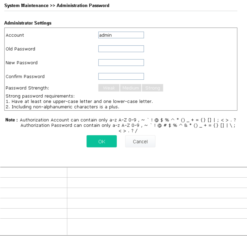
III-1-3 Administrator Password ........................................................................................................................92
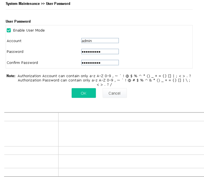
III-1-4 User Password .....................................................................................................................................93
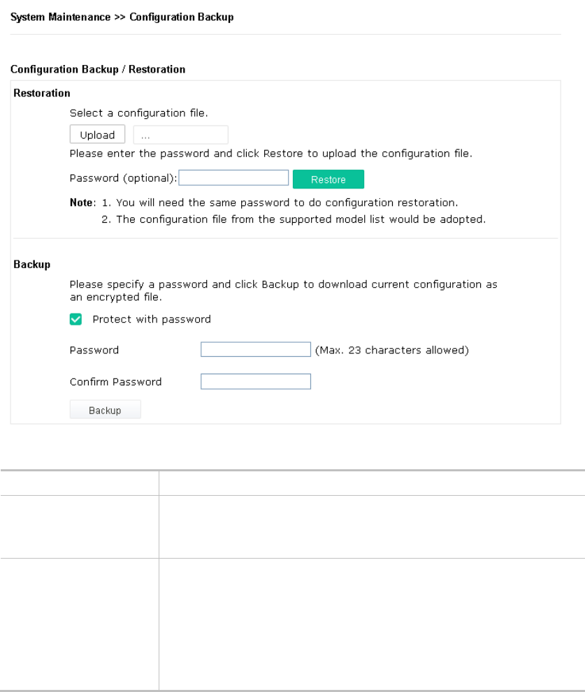
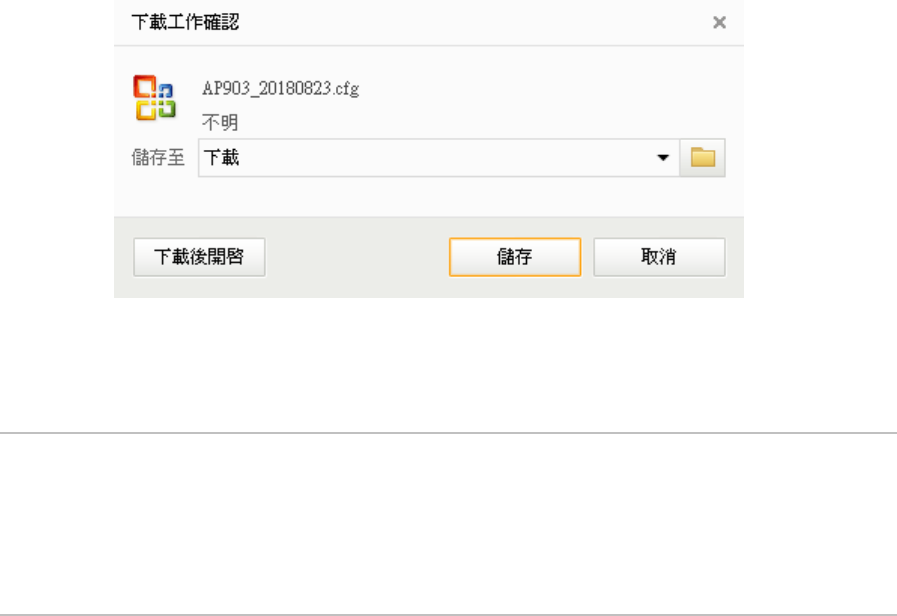
III-1-5 Configuration Backup............................................................................................................................94
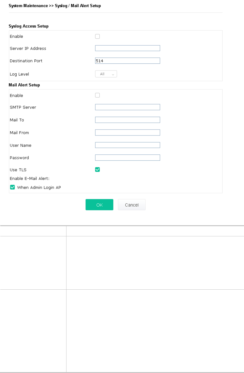
III-1-6 Syslog/Mail Alert...................................................................................................................................96
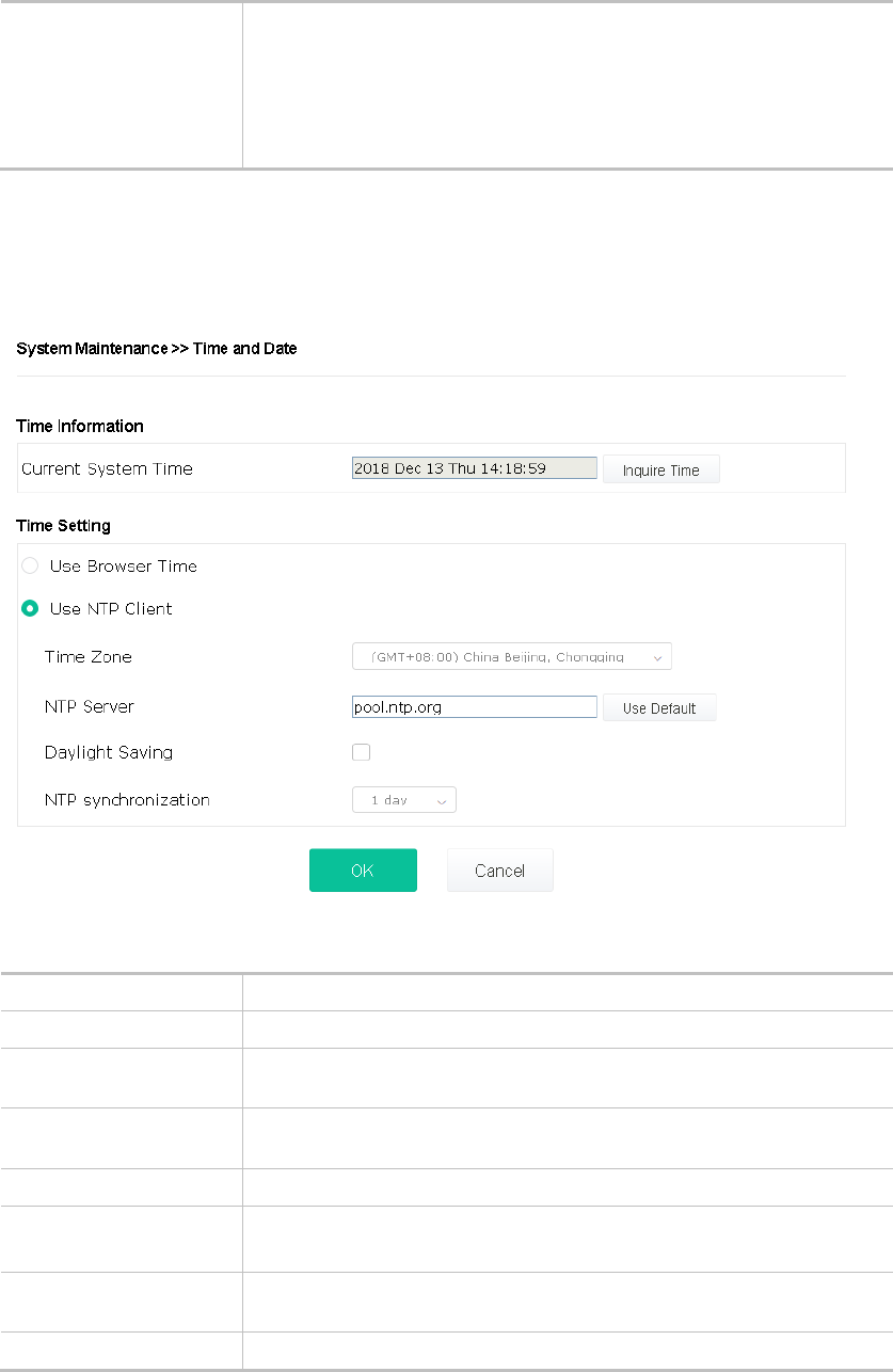
III-1-7 Time and Date .....................................................................................................................................97
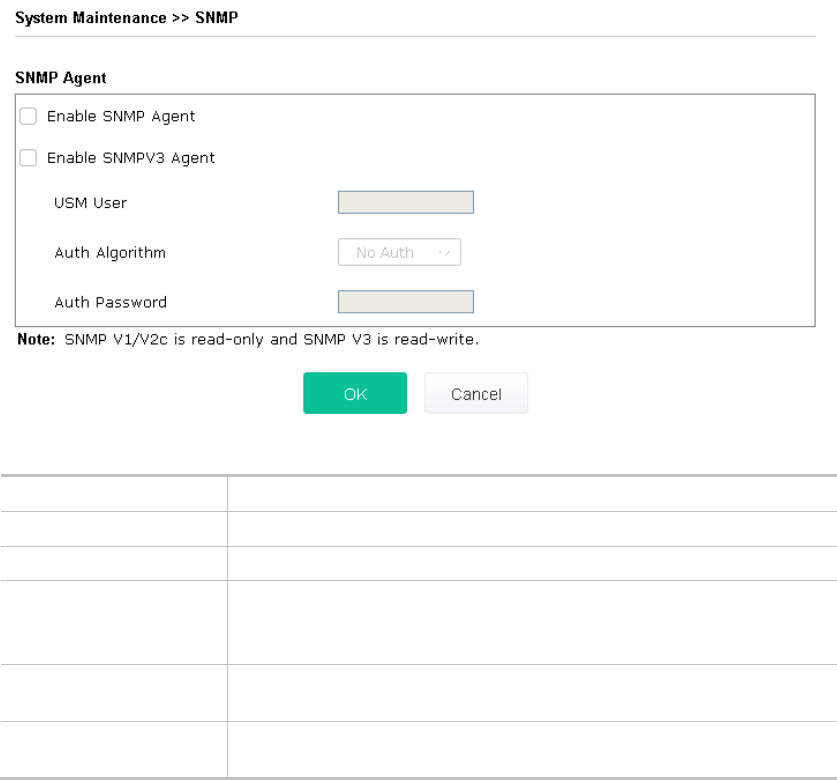
III-1-8 SNMP...................................................................................................................................................98
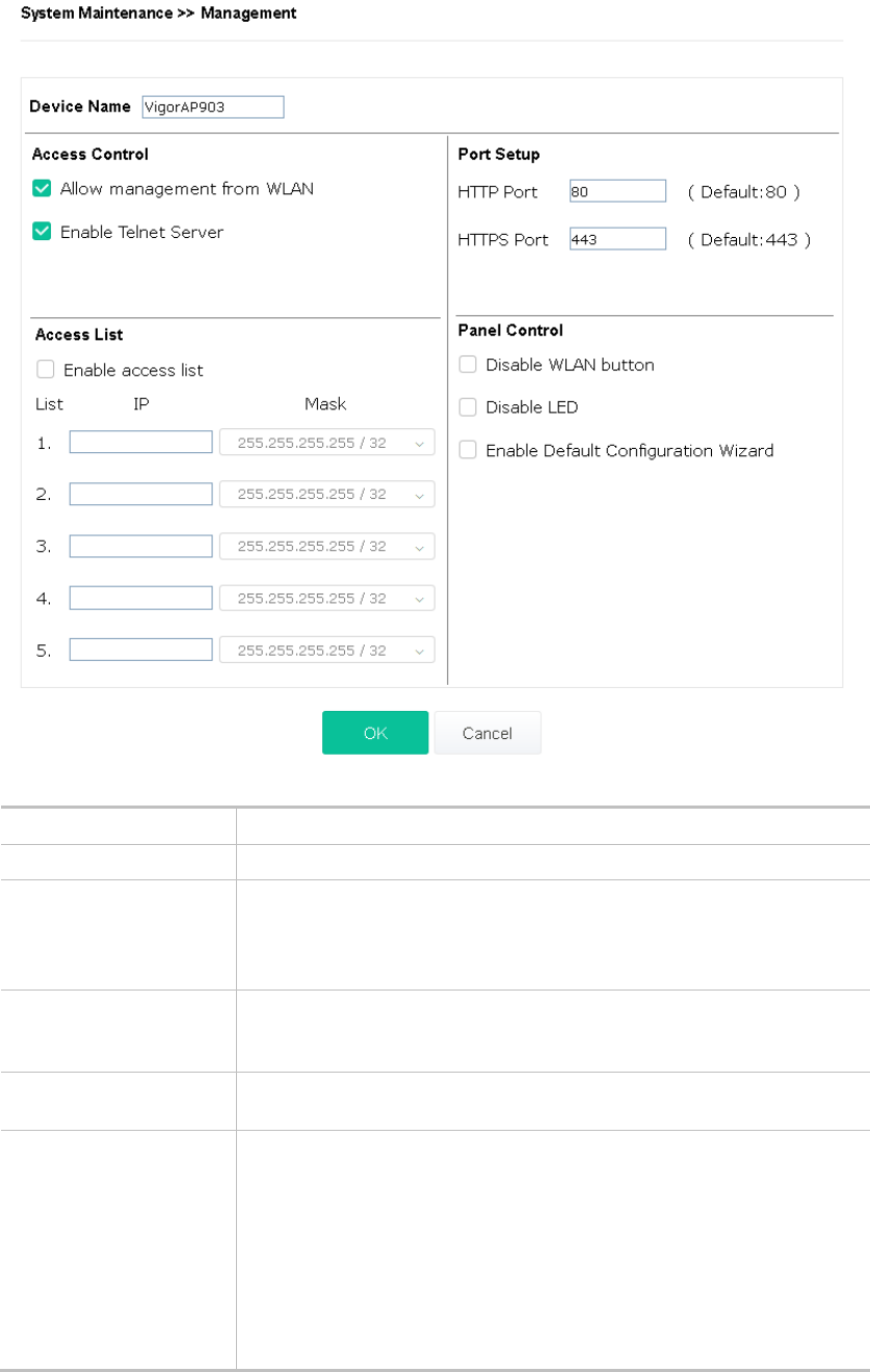
III-1-9 Management........................................................................................................................................99
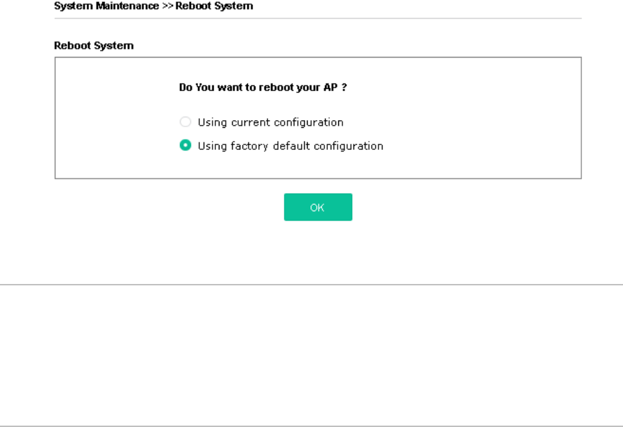
III-1-10 Reboot System ................................................................................................................................. 101
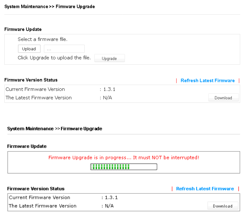
III-1-11 Firmware Upgrade............................................................................................................................ 102
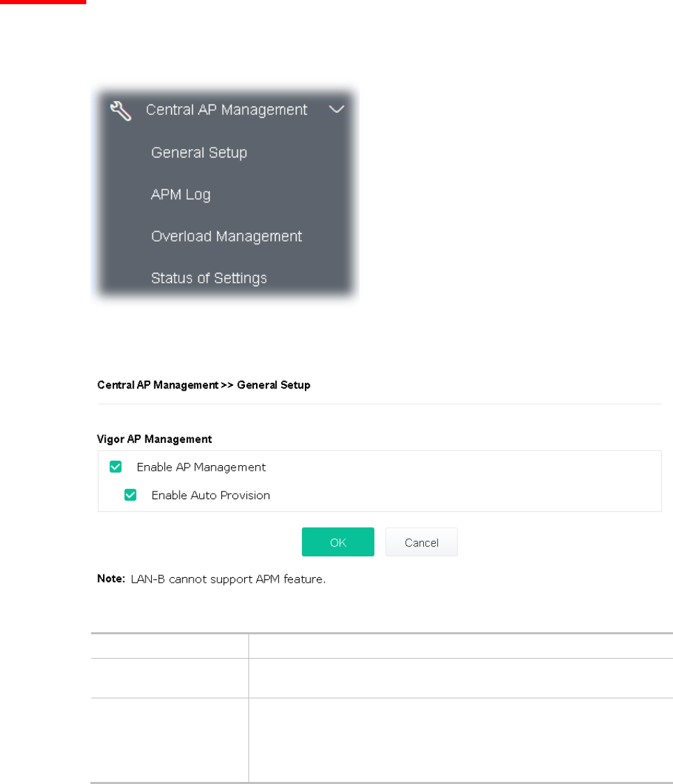
III-2 Central AP Management..................................................................................................................................... 103
III-2-1 General Setup .................................................................................................................................... 103
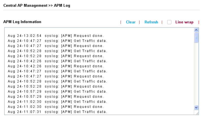
III-2-2 APM Log ............................................................................................................................................ 104
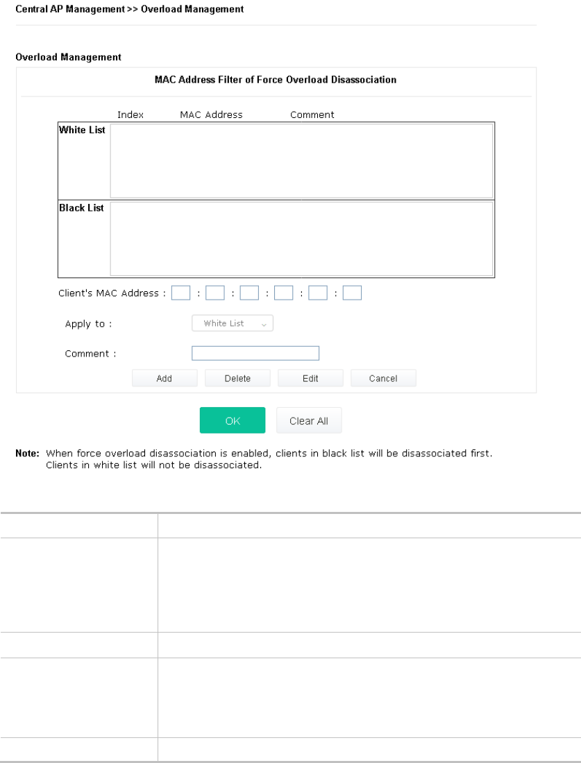
III-2-3 Overload Management........................................................................................................................ 105
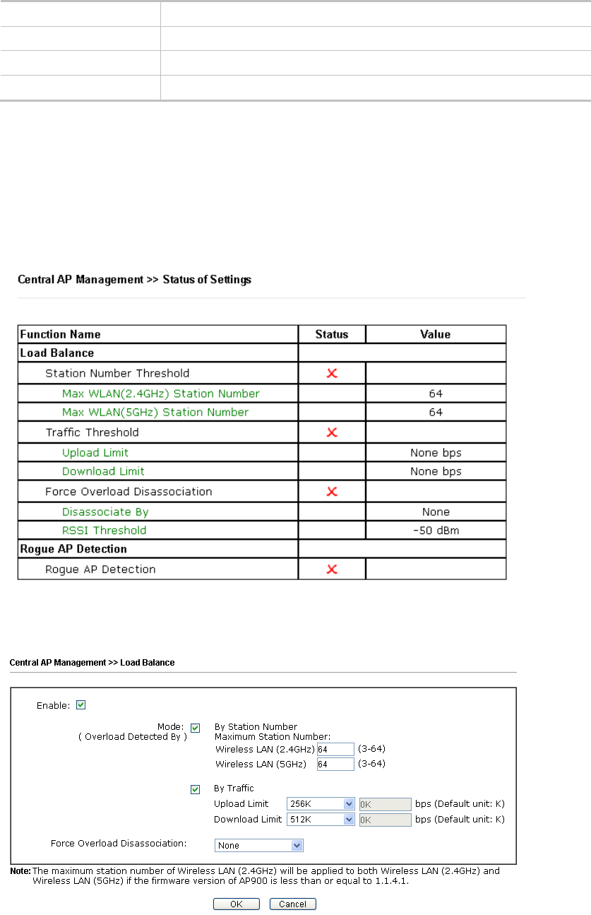
III-2-4 Status of Settings ............................................................................................................................... 106
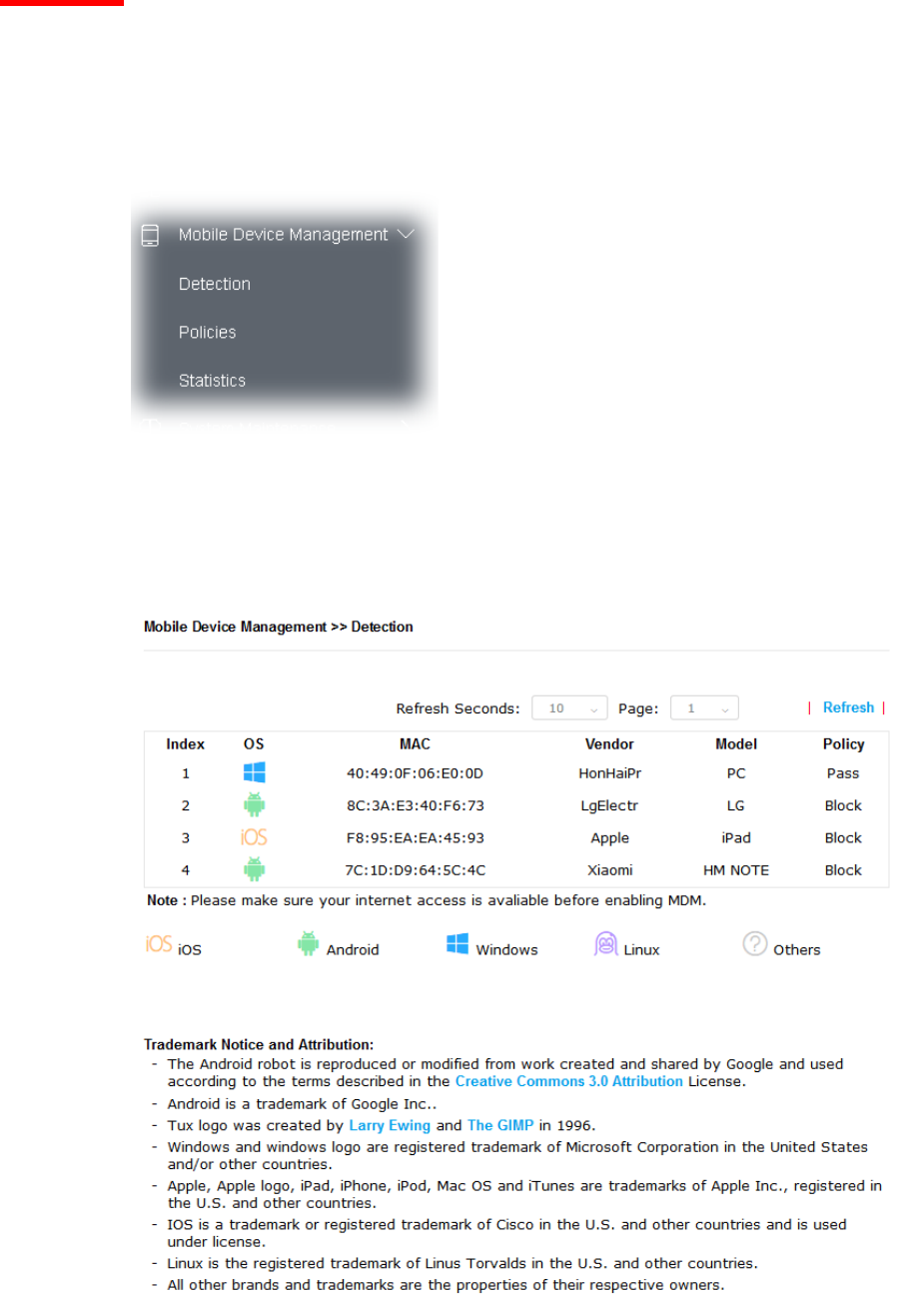
III-3 Mobile Device Management ................................................................................................................................ 107
III-3-1 Detection ........................................................................................................................................... 107
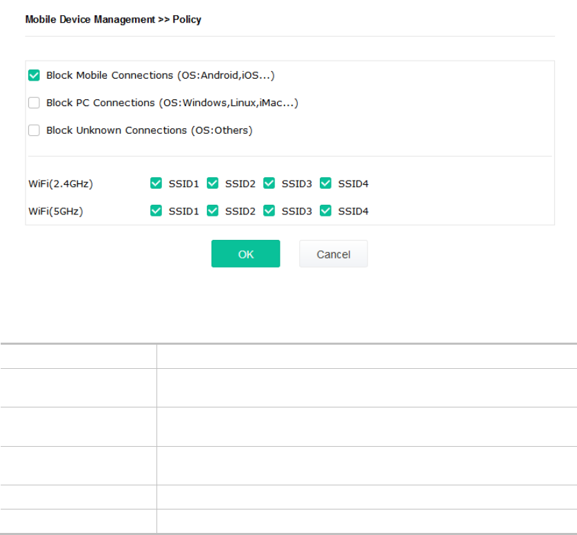
III-3-2 Policies .............................................................................................................................................. 108
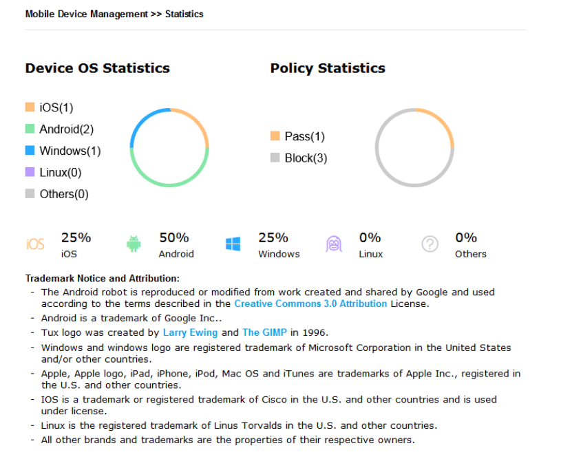
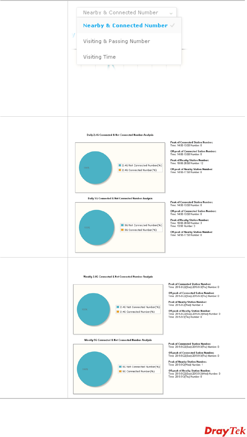
III-3-3 Statistics............................................................................................................................................ 109
Chapter IV Others ...................................................................................................................................... 111
IV-1 RADIUS Setting.................................................................................................................................................. 112
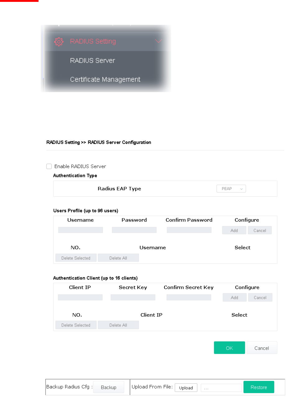
IV-1-1 RADIUS Server ................................................................................................................................... 112
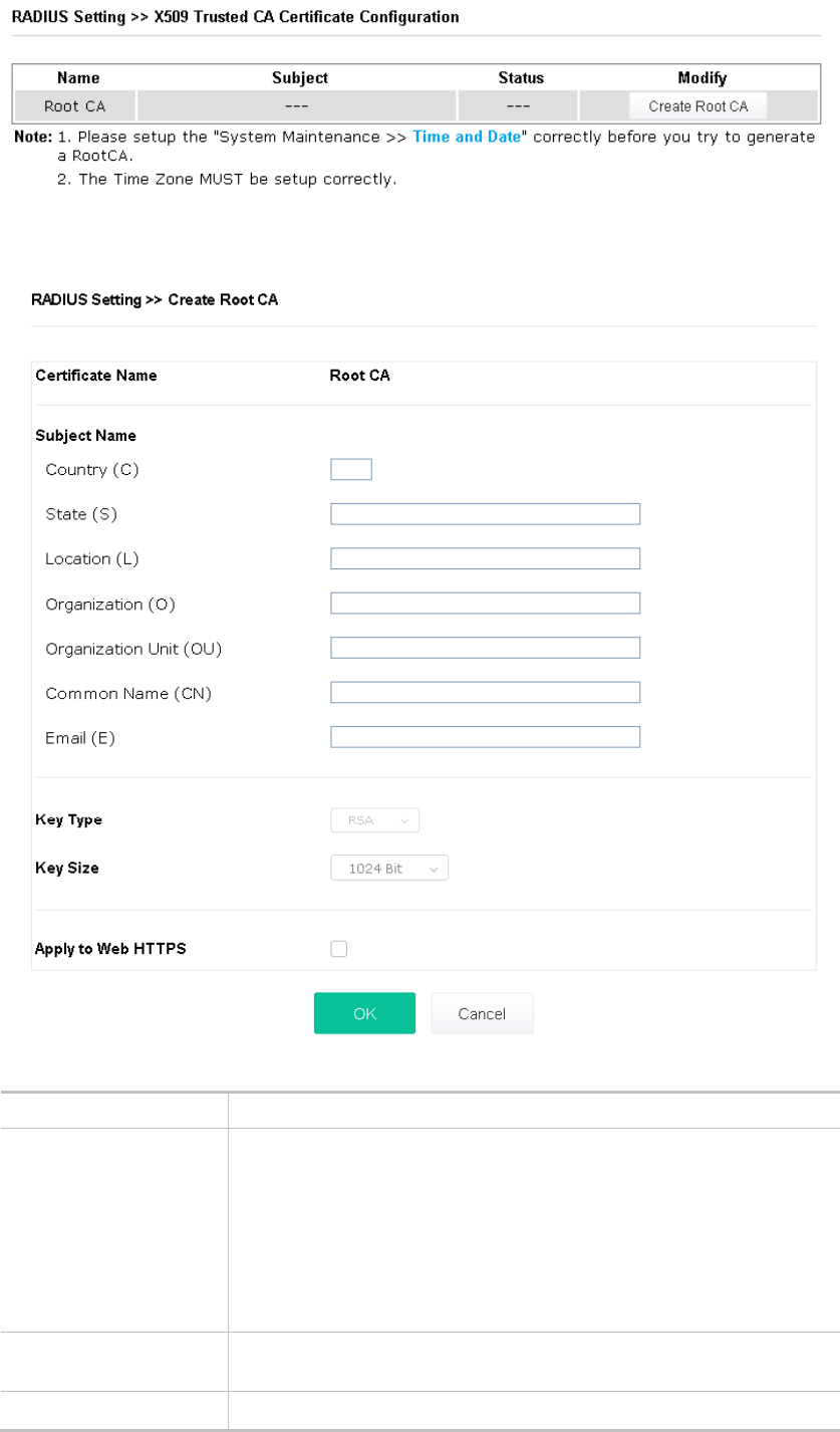
IV-1-2 Certificate Management....................................................................................................................... 113
IV-2 Applications ....................................................................................................................................................... 116
IV-2-1 Schedule ............................................................................................................................................ 116
IV-2-2 Apple iOS Keep Alive........................................................................................................................... 118
IV-2-3 Wi-Fi Auto On/Off ............................................................................................................................... 119
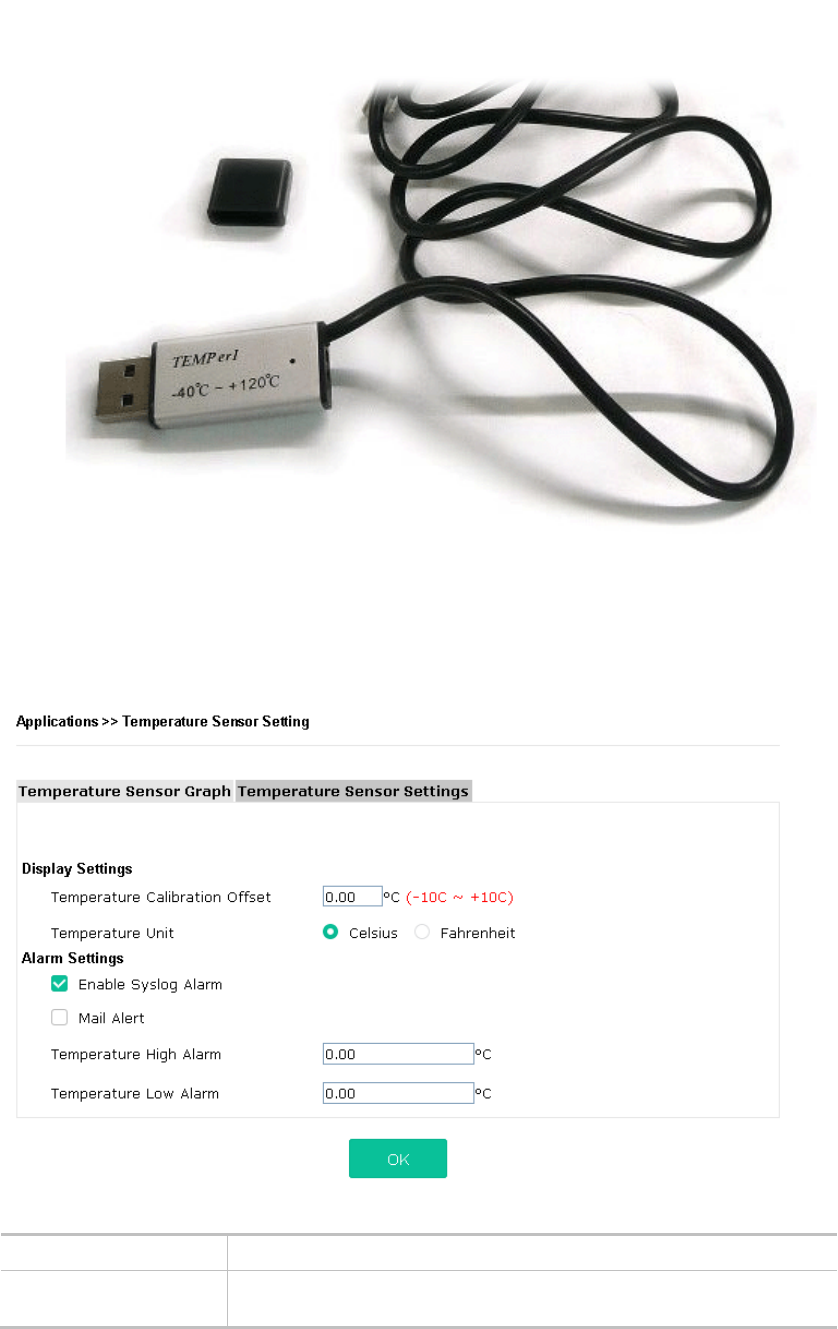
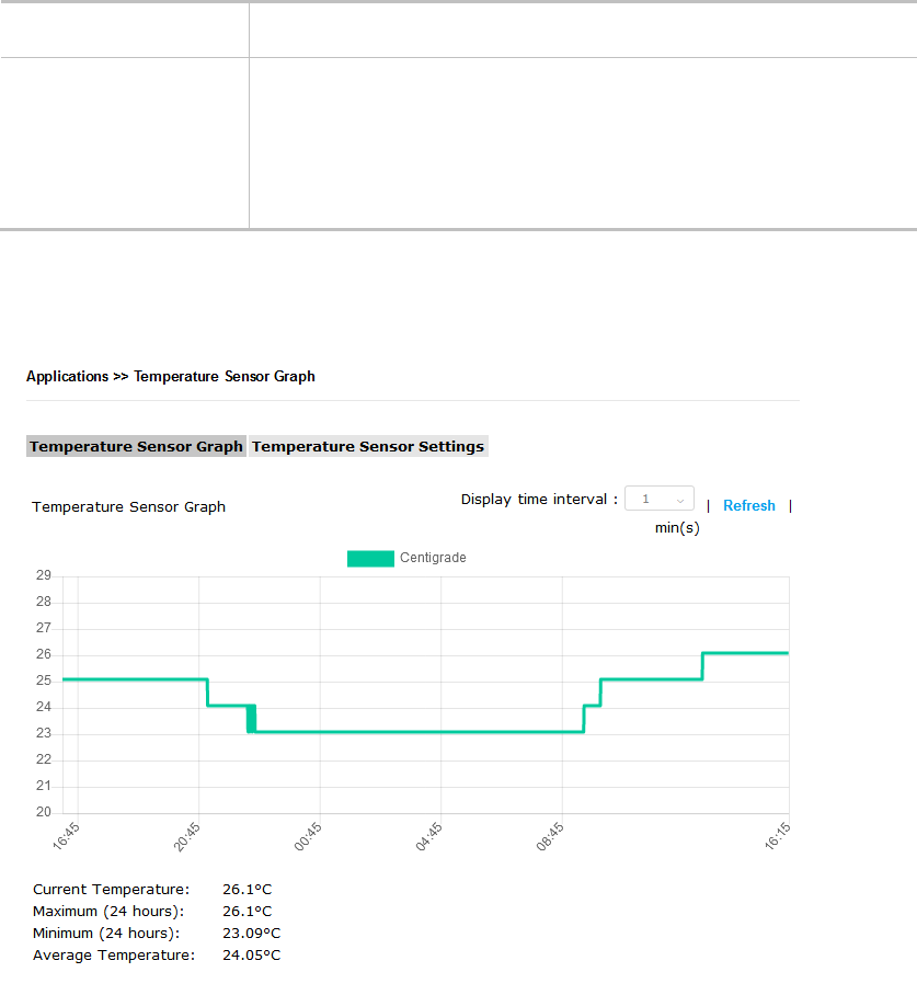
IV-2-4 Temperature Sensor............................................................................................................................ 120
Chapter V Troubleshooting ........................................................................................................................ 123
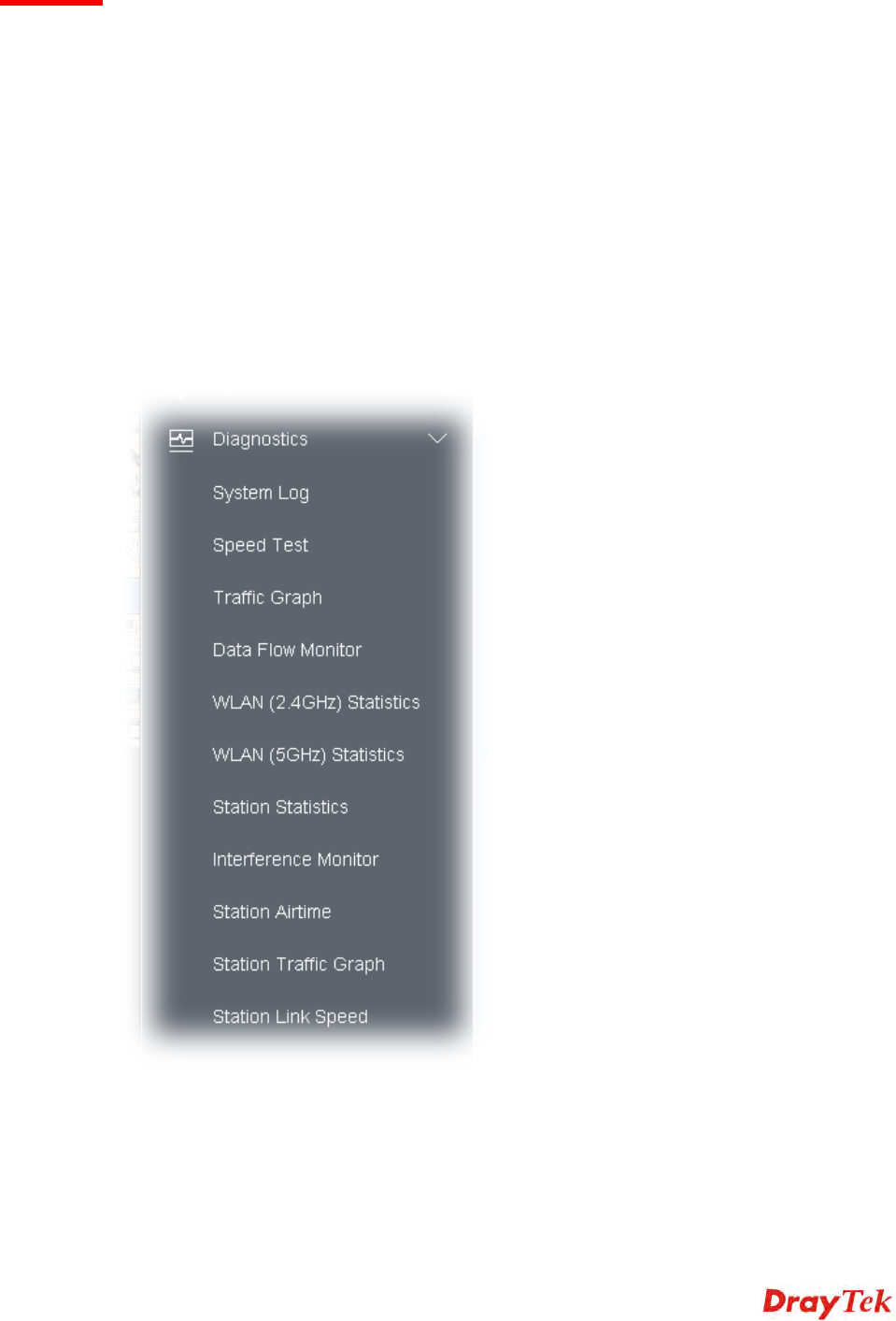
V-1 Diagnostics.......................................................................................................................................................... 124
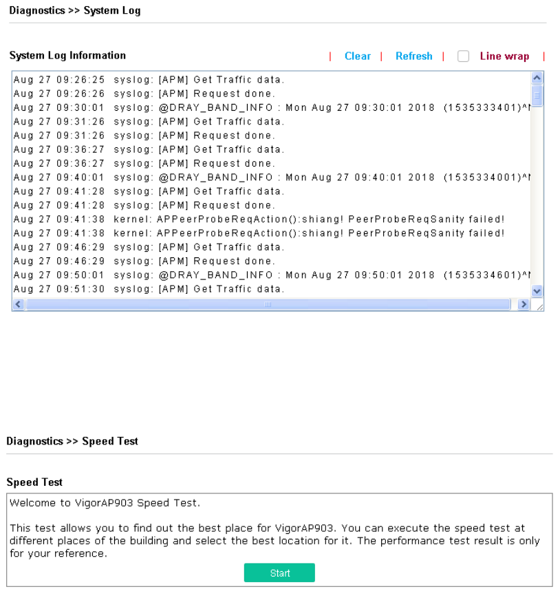
V-1-1 System Log.......................................................................................................................................... 125
V-1-2 Speed Test .......................................................................................................................................... 125
V-1-3 Traffic Graph........................................................................................................................................ 126
V-1-4 Data Flow Monitor................................................................................................................................ 126
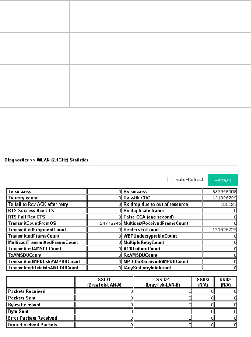
V-1-5 WLAN (2.4GHz) Statistics...................................................................................................................... 127
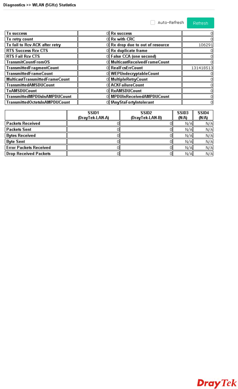
V-1-6 WLAN (5GHz) Statistics......................................................................................................................... 128
V-1-7 Station Statistics .................................................................................................................................. 129
V-1-8 Interference Monitor............................................................................................................................. 131
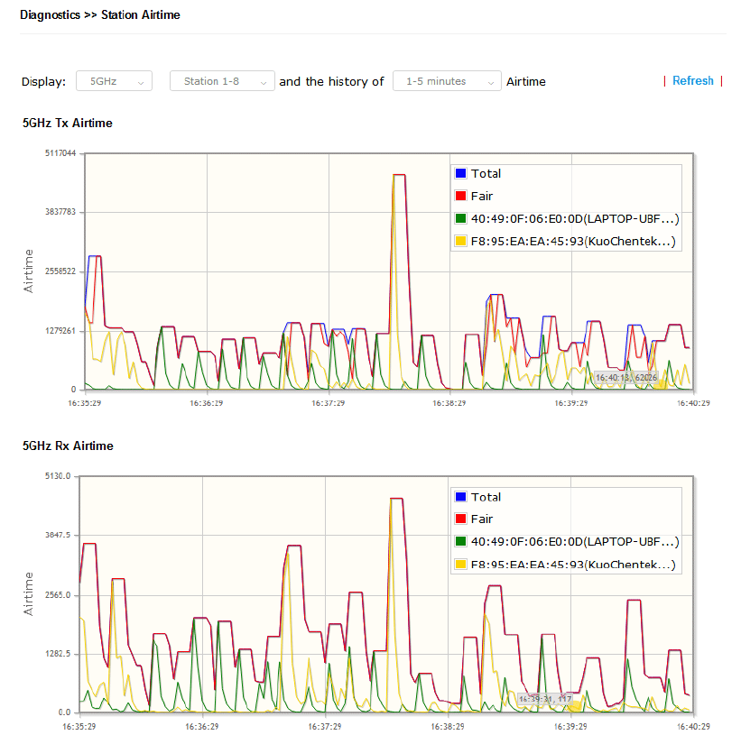
V-1-9 Station Airtime ..................................................................................................................................... 133
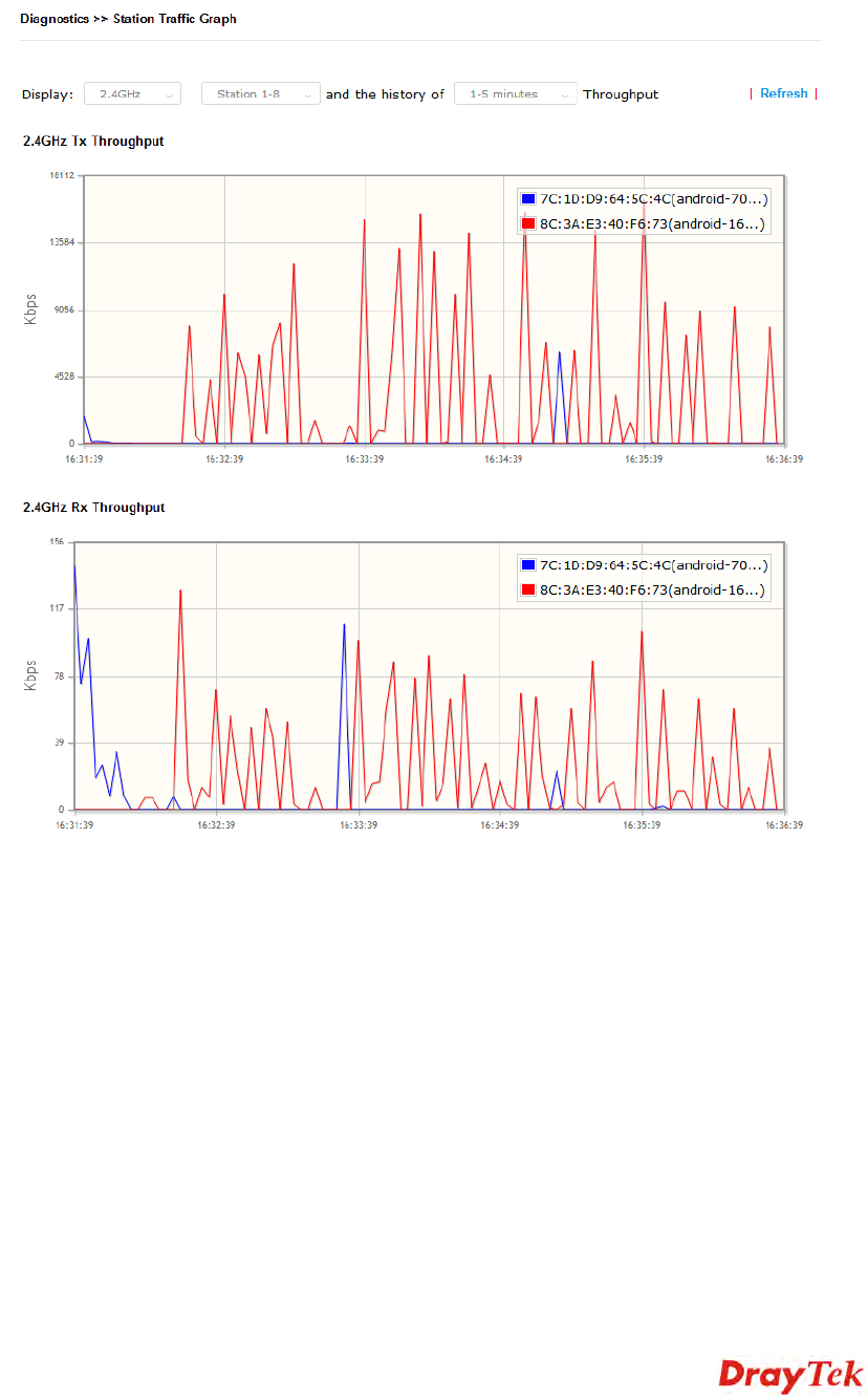
V-1-10 Station Traffic Graph .......................................................................................................................... 134
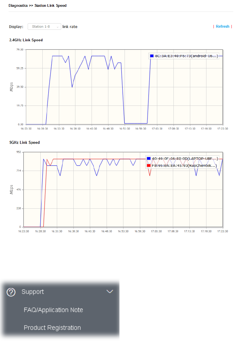
V-1-11 Station Link Speed.............................................................................................................................. 135
V-1-12 Support Area...................................................................................................................................... 135
V-2 Checking the Hardware Status.............................................................................................................................. 136
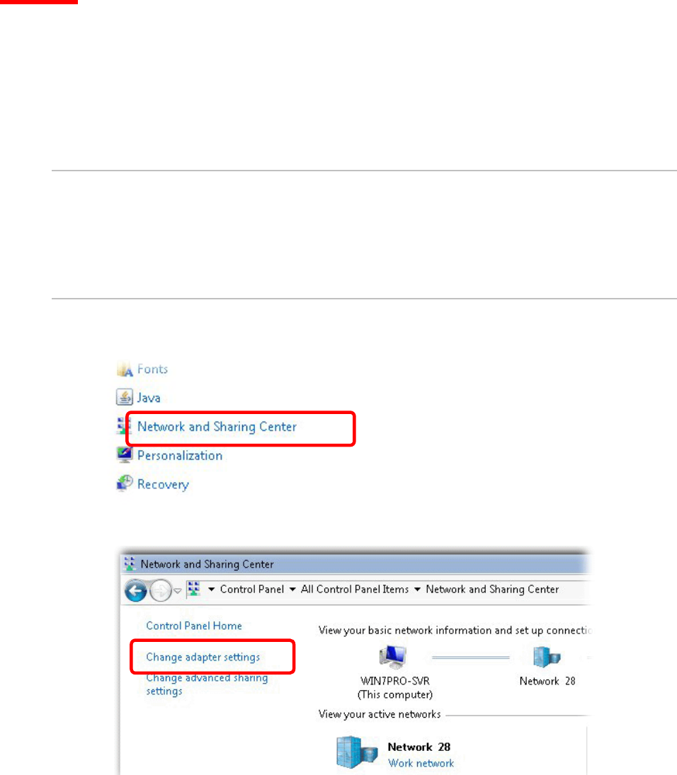
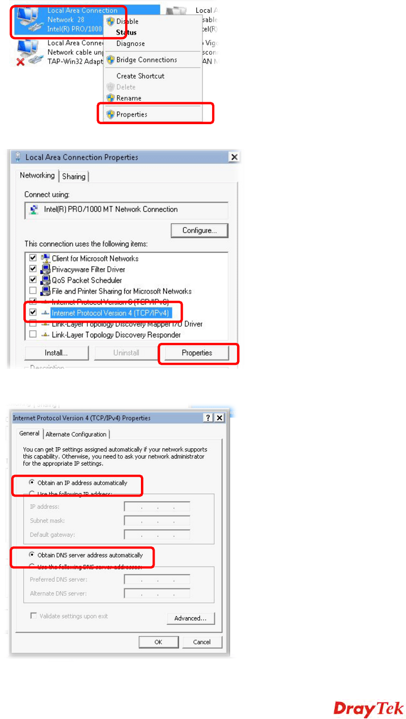
V-3 Checking the Network Connection Settings............................................................................................................ 137
V-3-1 For Windows........................................................................................................................................ 137
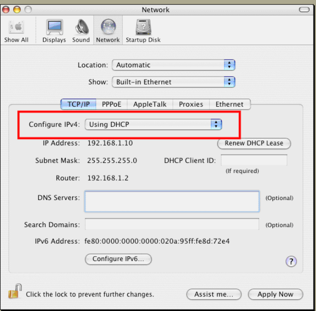
V-3-2 For Mac Os .......................................................................................................................................... 139
V-4 Pinging the Device............................................................................................................................................... 140
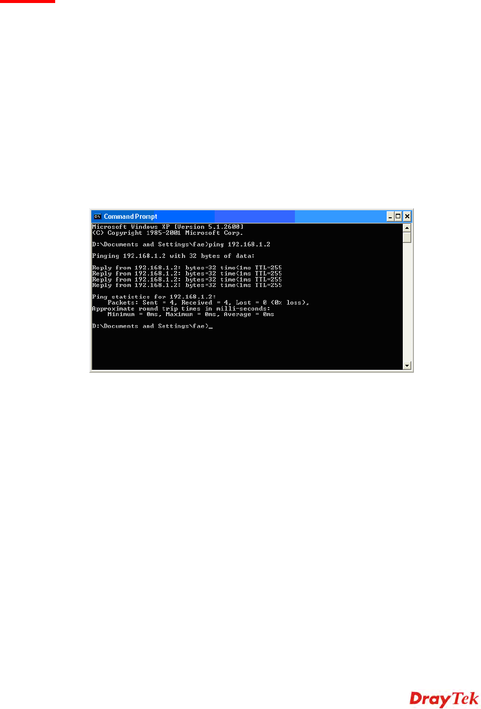
V-4-1 For Windows........................................................................................................................................ 140
V-4-2 For Mac Os (Terminal).......................................................................................................................... 140
V-5 Backing to Factory Default Setting ........................................................................................................................ 142
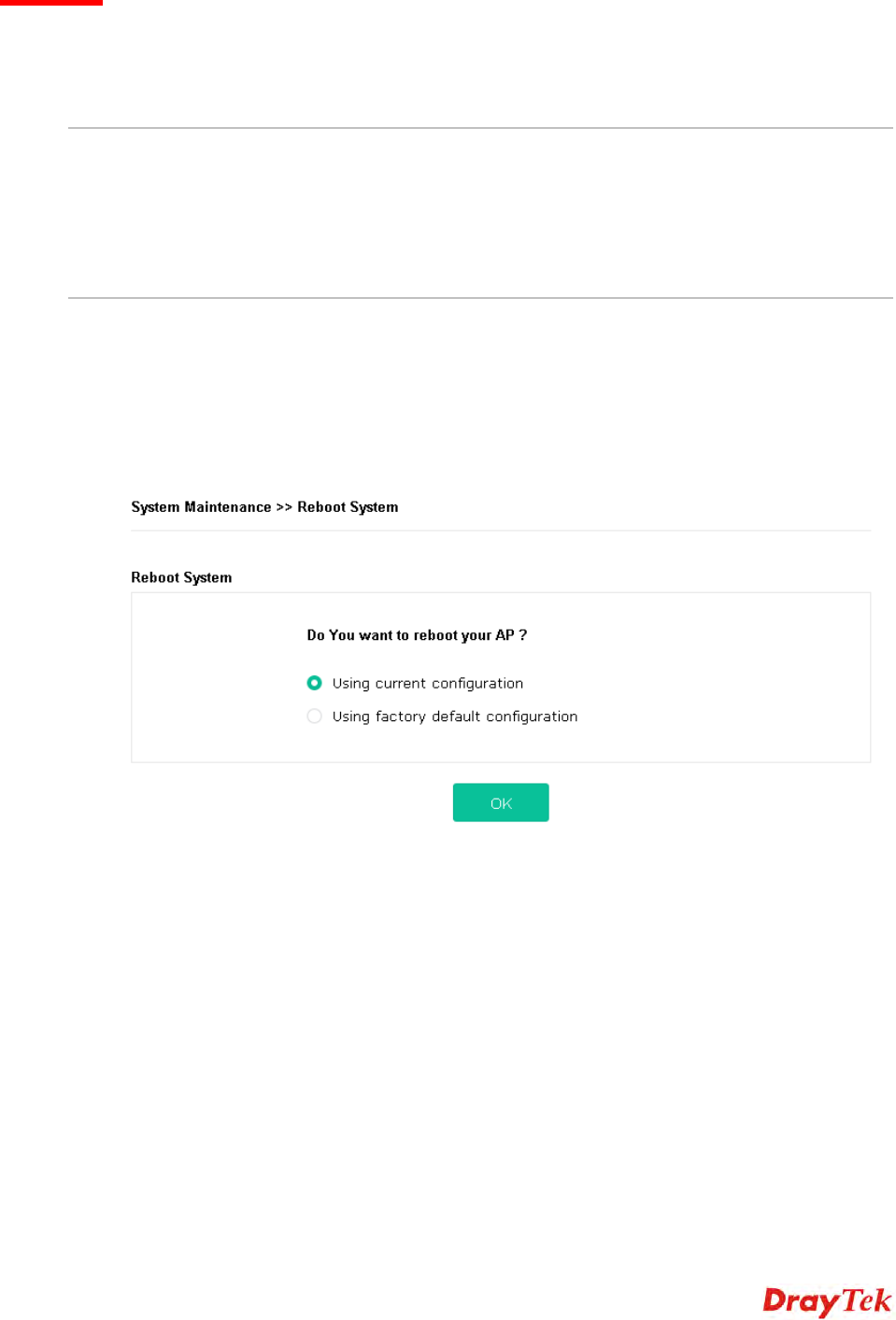
V-5-1 Software Reset..................................................................................................................................... 142
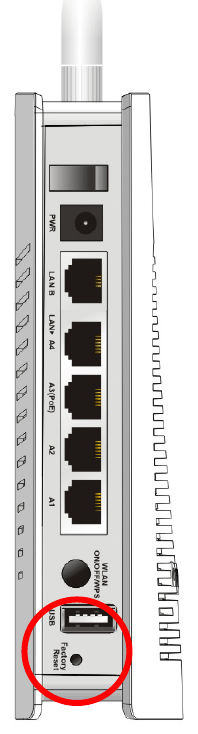
V-5-2 Hardware Reset ................................................................................................................................... 142
V-6 Contacting DrayTek.............................................................................................................................................. 144
Index........................................................................................................................................................................ 145
Chapter I Installation
1
I-1 Introduction
This is a generic International version of the user guide. Specification, compatibility and features vary by
region. For specific user guides suitable for your region or product, please contact local distributor.
Thank you for purchasing this VigorAP 903, the concurrent dual band wireless (2.4G/5G) access point
offering high-speed data transmission. With this high cost-efficiency VigorAP 903, computers and wireless
devices which are compatible with 802.11n/802.11a can connect to existing wired Ethernet network via
this VigorAP 903, at the speed of 300Mbps.
Easy install procedures allows any computer users to setup a network environment in very short time -
within minutes, even inexperienced users. Just follow the instructions given in this user manual, you can
complete the setup procedure and release the power of this access point all by yourself!
VigorAP 903 also is a Power over Ethernet Powered Device which adopts the technology of PoE for offering
power supply and transmitting data through the Ethernet cable.
AP Management
The VigorAP 903 can operate in standalone mode for your office network or a classroom or a waiting room
of some transportation terminals (e.g. ferry terminal, bus station, train station) or a clinic's waiting room ;
connected to your LAN and offering you with wireless access. If your network requires several VigorAP 903
units, to centrally manage and monitor them individually as a group will be expected. DrayTek central
wireless management (AP Management) lets control, efficiency, monitoring and security of your
company-wide wireless access easier be managed. Inside the web user interface, we call “central wireless
management” as Central AP Management which supports mobility, client monitoring / reporting and
load-balancing to multiple APs. For central wireless management, you will need a Vigor2860 or Vigor2925
series router; there is no per-node licensing or subscription required. With the unified user interface of
Vigor2860 Combo WAN series and Vigor2925 Triple WAN series, the multiple deployment of VigorAP 903
2
can be clear at the first sight. For multiple wireless clients to apply the AP Load Balancing to the multiple
APs, AP management will manage wireless traffic with smooth flow and enhanced efficiency.
Support Mesh Network
The message, information, and data can be transferred via wireless connection among VigorAP 903
devices without by using Ethernet cables. It can reduce the construction cost and eliminate the trouble of
wiring. Therefore, mesh AP is suitable for outdoor activities, or meetings.
In short, VigorAP with mesh function has the following benefits:
In the traditional wireless network, users must choose the best signal source manually from various
SSIDs. The mesh AP can find out the best route automatically.
Besides, if any one of the mesh AP devices disconnects due to unknown reason, the mesh system will
determine another accessible AP and transfer the packets to that AP.
Maintain a certain degree of normal operation for it is not easily affected by connection interference or
terrain blocking of walls or floors.
For the mesh network system adopts the mesh topology, each node in the network not only has a
single connection but also interweaves to other nodes like a net. Because of such characteristics, the
mesh network can set up stronger network architecture.
Each node (mesh AP) in the mesh network can be operated as an independent wireless AP; therefore,
the whole mesh network can offer a more stable and faster wireless connection.
The mesh network is suitable for large spaces and large numbers of people for the configuration for
each AP is easy and simple.
3
I-1-1 LED Indicators and Connectors
Before you use the Vigor modem, please get acquainted with the LED indicators and connectors first.
LED
Status Explanation
Off The system is not ready or is failed. ACT
Blinking The system is ready and can work normally.
On A USB device is connected and active. USB
Blinking The data is transmitting.
On Wireless function is ready.
Off Wireless function is not ready.
2.4G
Blinking Data is transmitting (sending/receiving).
On Wireless function is ready.
Off Wireless function is not ready.
5G
Blinking Data is transmitting (sending/receiving).
On A normal connection (rate with 100M/1000M) is through its
corresponding port.
Off LAN is disconnected.
LAN A1 - A4
Blinking Data is transmitting (sending/receiving).
On A normal connection (rate with 100M/1000M) is through its
corresponding port.
Off LAN is disconnected.
LAN B
Blinking Data is transmitting (sending/receiving).
Interface Description
4
Wireless band will be switched /changed
according to the button pressed and released.
For example,
2.4G (On) and 5G (On) – in default.
2.4G (Off) and 5G (On) – pressed and
released the button once.
2.4G (On) and 5G (Off) – pressed and
released the button twice.
2.4G (Off) and 5G (Off) – pressed and
released the button three times.
WPS - When WPS function is enabled by web
user interface, press this button for more than 2
seconds. The router will wait for any wireless
client connecting to it through WPS.
Restore the default settings. Usage: Turn on the
router. Press the button and keep for more than
10 seconds. Then the router will restart with the
factory default configuration.
LAN B
Connecter for xDSL / Cable modem (Giga level)
or router.
LAN A4, A3, A2
A1 (PoE)
Connecter for xDSL / Cable modem (Giga level) /
computer or router.
LAN A1 is used for PoE connection (for indoor
use).
PWR: Connecter for a power adapter.
Connecter for a USB device (for temperature
sensor).
Power switch.
Note:
For the sake of security, make the accessory kit away from children.
5
I-2 Hardware Installation
This section will guide you to install the VigorAP 903 through hardware connection and configure the
device’s settings through web browser.
Before starting to configure VigorAP 903, you have to connect your devices correctly.
I-2-1 Wired Connection for PC in LAN
1. Connect VigorAP 903 to ADSL modem, router, or switch/hub in your network through the LAN A
port of the access point by Ethernet cable.
2. Connect a computer to other available LAN A port. Make sure the subnet IP address of the PC is the
same as VigorAP 903 management IP, e.g., 192.168.1.X.
3. Connect the A/C power adapter to the wall socket, and then connect it to the PWR connector of the
access point.
4. Power on VigorAP 903.
5. Check all LEDs on the front panel. ACT LED should blink, LAN LEDs should be on if the access point
is correctly connected to the xDSL modem, router or switch/hub.
(For the detailed information of LED status, please refer to section I-1-1.)
6
I-2-2 Wired Connection for Notebook in WLAN
1. Connect VigorAP 903 to ADSL modem or router in your network through the LAN A port of the
access point by Ethernet cable.
2. Connect the A/C power adapter to the wall socket, and then connect it to the PWR connector of the
access point.
3. Power on VigorAP 903.
4. Check all LEDs on the front panel. ACT LED should be steadily on, LAN LEDs should be on if the
access point is correctly connected to the ADSL modem or router.
(For the detailed information of LED status, please refer to section I-1-1.)
7
I-2-3 Wireless Connection
VigorAP 903 can access Internet via an ADSL modem, router, or switch/hub in your network through
wireless connection.
1. Connect the A/C power adapter to the wall socket, and then connect it to the PWR connector of the
access point.
2. Power on VigorAP 903.
3. Check all LEDs on the front panel. ACT LED should be steadily on.
4. Connect VigorAP 903 to ADSL modem or router via wireless network.
(For the detailed information of LED status, please refer to section I-1-1.)
8
I-2-4 PoE Connection
VigorAP 903 can gain the power from the connected switch, e.g., VigorSwitch P2260. PoE (Power over
Ethernet) can break the install limitation caused by the fixed power supply.
1. Connect VigorAP 903 to a switch in your network through the LAN A4 (PoE) port of the access
point by Ethernet cable.
2. Connect a computer to VigorSwitch P2260. Make sure the subnet IP address of the PC is the same as
VigorAP 903 management IP, e.g., 192.168.1.X.
3. Power on VigorAP 903.
4. Check all LEDs on the front panel. ACT LED should be steadily on, LAN LEDs should be on if the
access point is correctly connected to the ADSL modem, router or switch/hub.
9
I-2-5 Wall-mount Connection
1. Drill two holes on the wall. The distance between the holes shall be 80mm. The recommended drill
diameter shall be 6.5mm (1/4”).
2. Fit screws into the wall using the appropriate type of wall plug.
3. Hang the VigorAP directly onto the screws.
Wall
10
I-3 Network IP Configuration
After the network connection is built, the next step you should do is setup VigorAP 903 with proper
network parameters, so it can work properly in your network environment.
Before you can connect to the access point and start configuration procedures, your computer must be
able to get an IP address automatically (use dynamic IP address). If it’s set to use static IP address, or
you’re unsure, please follow the following instructions to configure your computer to use dynamic IP
address:
For the default IP address of this AP is set “192.168.1.2”, we recommend you to use “192.168.1.X (except
2)” in the field of IP address on this section for your computer.
If the operating system of your computer is…
Windows 7 - please go to section I-3-1
Windows 2000 - please go to section I-3-2
Windows XP - please go to section I-3-3
Windows Vista - please go to section I-3-4
I-3-1 Windows 7 IP Address Setup
Click Start button (it should be located at lower-left corner of your computer), then click Control Panel.
Double-click Network and Internet, and the following window will appear. Click Network and
Sharing Center.
Next, click Change adapter settings and click Local Area Connection.
Then, select Internet Protocol Version 4 (TCP/IPv4) and click Properties.
11
Under the General tab, click Use the following IP address. Then input the following settings in
respective field and click OK when finish.
IP address: 192.168.1.9
Subnet Mask: 255.255.255.0
12
I-3-2 Windows 2000 IP Address Setup
Click Start button (it should be located at lower-left corner of your computer), then click control panel.
Double-click Network and Dial-up Connections
icon, double click Local Area Connection
,
and Local
Area Connection Properties window will appear. Select Internet Protocol (TCP/IP), then click
Properties.
Select Use the following IP address, then input the following settings in respective field and click OK
when finish.
IP address: 192.168.1.9
Subnet Mask: 255.255.255.0
13
I-3-3 Windows XP IP Address Setup
Click Start button (it should be located at lower-left corner of your computer), then click control panel.
Double-click Network and Internet Connections
icon, click Network Connections,
and then
double-click Local Area Connection, Local Area Connection Status window will appear, and then
click Properties.
Select Use the following IP address, then input the following settings in respective field and click OK
when finish:
IP address: 192.168.1.9
Subnet Mask: 255.255.255.0.
14
I-3-4 Windows Vista IP Address Setup
Click Start button (it should be located at lower-left corner of your computer), then click control panel.
Click View Network Status and Tasks, then click Manage Network Connections. Right-click Local
Area Netwrok, then select ‘Properties’. Local Area Connection Properties window will appear,
select Internet Protocol Version 4 (TCP / IPv4), and then click Properties.
Select Use the following IP address, then input the following settings in respective field and click OK
when finish:
IP address: 192.168.1.9
Subnet Mask: 255.255.255.0.
15
I-4 Accessing to Web User Interface
All functions and settings of this access point must be configured via web user interface. Please start your
web browser (e.g., Firefox).
1. Make sure your PC connects to the VigorAP 903 correctly.
2. Open a web browser on your PC and type http://192.168.1.2. A pop-up window will open to ask
for username and password. Pease type “admin/admin” on Username/Password and click OK.
Note:
You may either simply set up your computer to get IP dynamically from the router or set up the IP address
of the computer to be in the same subnet as the IP address of VigorAP 903.
If there is no DHCP server on the network, then VigorAP 903 will have an IP address of 192.168.1.2.
If there is DHCP available on the network, then VigorAP 903 will receive it’s IP address via the DHCP
server.
If you connect to VigorAP by wireless LAN, you could try to access the web user interface through
http://vigorap.com.
16
3. For the first time accessing VigorAP, the Quick Start Wizard for configuring wireless settings will
appear as follows. Refer to
Section I-7 Quick Start Wizard for detailed information
.
4. If VigorAP has been configured previously, the Dashboard of VigorAP will appear as follows:
17
5. The web page can be logged out by clicking Log Out on the top right of the web page. Or, logout
the web user interface according to the chosen condition. The default setting is Auto Logout, which
means the web configuration system will logout after 5 minutes without any operation. Change the
setting of auto logout if you want.
Note:
If you fail to access the web configuration, please go to the section “Trouble Shooting” for detecting and
solving your problem.
For using the device properly, it is necessary for you to change the password of web configuration for
security and adjust primary basic settings.
18
I-5 Changing Password
1. Please change the password for the original security of the modem.
2. Go to System Maintenance page and choose Administration Password.
3. Enter the new login password on the field of Password. Then click OK to continue.
4. Now, the password has been changed. Next time, use the new password to access the Web User
Interface for this modem.
19
I-6 Dashboard
Dashboard shows system status including the number of client connected, throughput, gateway, physical
connection status, radio (2.4GHz / 5GHz) status, backhaul network, recent activities, wireless network
usage, and so on.
Click Dashboard from the main menu on the left side of the main page.
20
I-7 Quick Start Wizard
Quick Start Wizard will guide you to configure 2.4G wireless setting, 5G wireless setting and other
corresponding settings for Vigor Access Point step by step.
Available operation mode includes:
Access Point
Mesh Root
Mesh Node
Range Extender
In this page, the advanced settings pages will vary according to the operation mode specified.
21
I-7-1 Settings for Access Point
1. Choose Access Point as the operation mode and click Next Step.
2. In the following page, configure the settings for wireless LAN (for both 2.4GHz and 5GHz) and click
Next Step.
Available settings are explained as follows:
Item Description
WiFi Name Set a name for VigorAP 903 to be identified.
WiFi Password Type 8~63 ASCII characters, such as 012345678..(or 64 Hexadecimal
22
digits leading by 0x, such as "0x321253abcde...").
Enable Guest
Wireless
Check the box to enable the guest wireless setting.
Such feature is especially useful for free Wi-Fi service. For example, a
coffee shop offers free Wi-Fi service for its guests for one hour every day.
Guest WiFi Name - Set a name for VigorAP 903 which can be identified
and connected by wireless guest.
Guest WiFi Password - Set 8~63 ASCII characters which can be used
for logging into VigorAP 903 by wireless guest.
Enable
Bandwidth Limit
Check the box to define the maximum speed of the data
uploading/downloading which will be used for the guest connecting to
Vigor device with the same SSID.
Upload Limit – Scroll the radio button to choose the value you want.
Download Limit –Scroll the radio button to choose the value you want.
Enable Station
Control
Check the box to set the duration for the guest connecting /reconnecting
to Vigor device.
Connection Time –Scroll the radio button to choose the value you want.
Reconnection Time –Scroll the radio button to choose the value you
want.
3. Change the default password for such device with new value. Then click Next Step.
Available settings are explained as follows:
Item Description
Admin Password Enter a new password.
Confirm
Password
Enter the new password again for confirmation.
4. A summary of settings configuration will be shown on screen. Click Finish.
23
24
I-7-2 Settings for Mesh Root
1. Choose Mesh Root as the operation mode and click Next Step.
2. Configure the settings for wireless LAN (for both 2.4GHz and 5GHz) and click Next Step.
Available settings are explained as follows:
Item Description
WiFi Name Set a name for VigorAP 903 to be identified.
WiFi Password Type 8~63 ASCII characters, such as 012345678..(or 64 Hexadecimal
digits leading by 0x, such as "0x321253abcde...").
Enable Guest Check the box to enable the guest wireless setting.
25
Wireless Such feature is especially useful for free Wi-Fi service. For example, a
coffee shop offers free Wi-Fi service for its guests for one hour every day.
Guest WiFi Name - Set a name for VigorAP 903 which can be identified
and connected by wireless guest.
Guest WiFi Password - Set 8~63 ASCII characters or 8~63 ASCII
characters which can be used for logging into VigorAP 903 by wireless
guest.
Enable
Bandwidth Limit
Check the box to define the maximum speed of the data
uploading/downloading which will be used for the guest connecting to
Vigor device with the same SSID.
Upload Limit – Scroll the radio button to choose the value you want.
Download Limit –Scroll the radio button to choose the value you want.
Enable Station
Control
Check the box to set the duration for the guest connecting /reconnecting
to Vigor device.
Connection Time –Scroll the radio button to choose the value you want.
Reconnection Time –Scroll the radio button to choose the value you
want.
3. Change the default password for such device with new value. Then click Next Step.
Available settings are explained as follows:
Item Description
Admin Password Enter a new password.
Confirm
Password
Enter the new password again for confirmation.
4. A summary of settings configuration will be shown on screen. Click Finish.
26
5. After clicking Finish, the following web page appears. VigorAP will search for mesh node around the
network.
27
6. Available VigorAP devices will be shown on the screen. Select the device (as a mesh node) for
grouping under such mesh group and enter a device name for identification.
7. Click Apply and wait for a while.
28
8. Later, a summary page of mesh root with mesh node will be shown on the screen.
29
I-7-3 Settings for Mesh Node
1. Choose Mesh Node as the operation mode and click Next Step.
2. A summary of settings configuration will be shown on screen. Click Finish.
30
I-7-4 Settings for Range Extender
1. Choose Range Extender as the operation mode and click Next Step.
2. Configure the settings for wireless LAN (for both 2.4GHz and 5GHz) and click Next Step.
Available settings are explained as follows:
Item Description
WiFi Name Set a name for VigorAP 903 to be identified.
WiFi Password Type 8~63 ASCII characters, such as 012345678..(or 64 Hexadecimal
digits leading by 0x, such as "0x321253abcde...").
Enable Guest
Wireless
Check the box to enable the guest wireless setting.
Such feature is especially useful for free Wi-Fi service. For example, a
coffee shop offers free Wi-Fi service for its guests for one hour every day.
31
Guest WiFi Name - Set a name for VigorAP 903 which can be identified
and connected by wireless guest.
Guest WiFi Password - Set 8~63 ASCII characters or 8~63 ASCII
characters which can be used for logging into VigorAP 903 by wireless
guest.
Enable
Bandwidth Limit
Check the box to define the maximum speed of the data
uploading/downloading which will be used for the guest connecting to
Vigor device with the same SSID.
Upload Limit – Scroll the radio button to choose the value you want.
Download Limit –Scroll the radio button to choose the value you want.
Enable Station
Control
Check the box to set the duration for the guest connecting /reconnecting
to Vigor device.
Connection Time –Scroll the radio button to choose the value you want.
Reconnection Time –Scroll the radio button to choose the value you
want.
3. Change the default password for such device with new value. Then click Next Step.
Available settings are explained as follows:
Item Description
Admin Password Enter a new password.
Confirm
Password
Enter the new password again for confirmation.
4. In the following page, click Search to find out neighboring access point. When all the available access
points appear on the page, click the one you want to connect. Corresponding settings (e.g., SSID,
security key) of the selected device will be shown below. Then click Next Step.
32
Available settings are explained as follows:
Item Description
SSID/Security
Key
Once the access point specified above, the name / security key of the AP
will be shown automatically in these fields.
Channel Means the channel frequency of the wireless LAN. You may switch channel
if the selected channel is under serious interference.
Security Mode There are several modes provided for you to choose. Each mode will bring
up different parameters (e.g., WEP keys, Pass Phrase) for you to configure.
Encryption Type Available options will vary according to the selected Security Mode.
When Open is selected:
Choose None to disable the WEP Encryption. Data sent to the AP will
not be encrypted.
WEP Keys –To enable WEP encryption for data transmission, please
choose WEP. Four keys can be entered here, but only one key can be
selected at a time. The format of WEP Key is restricted to 5 ASCII
characters or 10 hexadecimal values in 64-bit encryption level, or
restricted to 13 ASCII characters or 26 hexadecimal values in 128-bit
encryption level. The allowed content is the ASCII characters from
33(!) to 126(~) except '#' and ','.
When Shared is selected:
WEP Keys - To enable WEP encryption for data transmission, please
choose WEP. Four keys can be entered here, but only one key can be
selected at a time. The format of WEP Key is restricted to 5 ASCII
characters or 10 hexadecimal values in 64-bit encryption level, or
restricted to 13 ASCII characters or 26 hexadecimal values in 128-bit
encryption level. The allowed content is the ASCII characters from
33(!) to 126(~) except '#' and ','.
When WPA/PSK or WPA2/PSK is selected:
Select TKIP or AES as the algorithm for WPA.
Security Key - Select WEP, TKIP or AES as the encryption algorithm.
33
Type 8~63 ASCII characters, such as 012345678..(or 64
Hexadecimal digits leading by 0x, such as "0x321253abcde...").
5. A summary of settings configuration will be shown on screen. Click Finish.
34
This page is left blank.
35
Chapter II Connectivity
36
II-1 Operation Mode
This page provides several available modes for you to choose for different conditions. Click any one of
them and click OK. The system will configure the required settings automatically.
Available settings are explained as follows:
Item Description
AP This mode allows wireless clients to connect to access point and exchange
data with the devices connected to the wired network.
Mesh Mesh Root – VigorAP must connect to a gateway with an Ethernet cable.
Mesh Node – VigorAP can connect to other mesh root via wireless
connection. A mesh network creates one set of links automatically and
calculates the most optimal wireless path through the wireless network
back to a wired mesh root.
Range Extender VigorAP can act as a wireless repeater which will help you to extend the
networking wirelessly. The access point can act as Station and AP at the
same time. It can use Station function to connect to a Root AP and use AP
function to service all wireless clients within its coverage.
Note:
The Wireless LAN settings will be changed according to the Operation Mode selected here. For the
detailed information, please refer to the section of Wireless LAN.
37
II-2 General Concepts for Wireless LAN (2.4GHz/5GHz)
VigorAP 903 is a highly integrated wireless local area network (WLAN) for 5 GHz 802.11ac or 2.4/5 GHz
802.11n WLAN applications. It supports channel operations of 20/40 MHz at 2.4 GHz and 20/40/80 MHz at
5 GHz. VigorAP 903 can support data rates up to 867 MBps in 802.11ac 80 MHz channels.
Note:
* The actual data throughput will vary according to the network conditions and
environmental factors, including volume of network traffic, network overhead and building
materials.
VigorAP 903 plays a role as an Access Point (AP) connecting to lots of wireless clients or Stations (STA). All
the STAs will share the same Internet connection via VigorAP 903. The General Setup will set up the
information of this wireless network, including its SSID as identification, located channel etc.
Security Overview
WEP (Wired Equivalent Privacy) is a legacy method to encrypt each frame transmitted via radio using
either a 64-bit or 128-bit key. Usually access point will preset a set of four keys and it will communicate
with each station using only one out of the four keys.
WPA (Wi-Fi Protected Access), the most dominating security mechanism in industry, is separated into two
categories: WPA-personal or called WPA Pre-Share Key (WPA/PSK), and WPA-Enterprise or called
WPA/802.1x.
In WPA-Personal, a pre-defined key is used for encryption during data transmission. WPA applies Temporal
Key Integrity Protocol (TKIP) for data encryption while WPA2 applies AES. The WPA-Enterprise combines
not only encryption but also authentication.
Since WEP has been proved vulnerable, you may consider using WPA for the most secure connection. You
should select the appropriate security mechanism according to your needs. No matter which security suite
you select, they all will enhance the over-the-air data protection and /or privacy on your wireless network.
The VigorAP 903 is very flexible and can support multiple secure connections with both WEP and WPA at
the same time.
WPS Introduction
WPS (Wi-Fi Protected Setup) provides easy procedure to make network connection between wireless
station and wireless access point (VigorAP 903) with the encryption of WPA and WPA2.
38
It is the simplest way to build connection between wireless network clients and VigorAP 903. Users do not
need to select any encryption mode and type any long encryption passphrase to setup a wireless client
every time. He/she only needs to press a button on wireless client, and WPS will connect for client and
VigorAP 903 automatically.
Note:
Such function is available for the wireless station with WPS supported.
There are two methods to do network connection through WPS between AP and Stations: pressing the
Start PBC
button or using
PIN Code
.
On the side of VigorAP 903 series which served as an AP, press WPS button once on the front panel of
VigorAP 903 or click Start PBC on web configuration interface. On the side of a station with network card
installed, press Start PBC button of network card.
If you want to use PIN code, you have to know the PIN code specified in wireless client. Then provide the
PIN code of the wireless client you wish to connect to the VigorAP 903.
39
40
II-3 Wireless LAN (2.4GHz/5GHz) Settings for AP Mode
When you choose AP as the operation mode, the Wireless LAN menu items will include General Setup,
Security, Access Control, WPS, Advanced Setting, AP Discovery, Bandwidth Management, Airtime Fairness,
Station Control, Roaming, Band Steering and Station List.
Note:
Available settings for Wireless LAN (2.4GHz) and Wireless LAN (5Ghz) are almost the same, except
for Band Steering.
The following figure shows how VigorAP runs as AP (Access Point)
41
II-3-1 General Setup
By clicking the General Setup, a new web page will appear so that you could configure the SSID, the
wireless channel and WDS (for 5GHz only). Please refer to the following figure for more information.
Available settings are explained as follows:
Item Description
Enable Wireless LAN Check the box to enable wireless function.
Enable Client Limit Check the box to set the maximum number of wireless stations which try to
connect Internet through Vigor device. The number you can set is from 3
Available for
5GHz Access
Point Mode
42
to 64.
Enable Client Limit per
SSID
Define the maximum number of wireless stations per SSID which try to
connect to Internet through Vigor device. The number you can set is from
3 to 64.
Mode At present, VigorAP 903 can connect to 11b only, 11g only, 11n only, Mixed
(11b+11g), Mixed (11g+11n) and Mixed (11b+11g+11n) stations
simultaneously. Simply choose Mixed (11b+11g+11n) mode.
Channel Means the channel of frequency of the wireless LAN. You may switch
channel if the selected channel is under serious interference. If you have
no idea of choosing the frequency, please select AutoSelect to let system
determine for you.
Extension Channel With 802.11n, there is one option to double the bandwidth per channel.
The available extension channel options will be varied according to the
Channel selected above. Configure the extension channel you want.
Enable 2 Subnet
(Simulate 2 APs)
Check the box to enable the function for two independent subnets. Once
you enable this function, LAN-A and LAN-B would be independent. Next,
you can connect one router in LAN-A, and another router in LAN-B. Such
mechanism can make you feeling that you have two independent
AP/subnet functions in one VigorAP 903.
If you disable this function, LAN-A and LAN-B ports are in the same
domain. You could only connect one router (no matter connecting to
LAN-A or LAN-B) in this environment.
Hide SSID Check it to prevent from wireless sniffing and make it harder for
unauthorized clients or STAs to join your wireless LAN. Depending on the
wireless utility, the user may only see the information except SSID or just
cannot see any thing about VigorAP 903 while site surveying. The system
allows you to set four sets of SSID for different usage.
SSID Set a name for VigorAP 903 to be identified. Default settings are
DrayTek-LAN-A and DrayTek-LAN-B. When Enable 2 Subnet is enabled,
you can specify subnet interface (LAN-A or LAN-B) for each SSID by using
the drop down menu.
Subnet Choose LAN-A or LAN-B for each SSID. If you choose LAN-A, the wireless
clients connecting to this SSID could only communicate with LAN-A.
Isolate Member Check this box to make the wireless clients (stations) with the same SSID
not access for each other.
VLAN ID Type the value for such SSID. Packets transferred from such SSID to LAN
will be tagged with the number.
If your network uses VLANs, you can assign the SSID to a VLAN on your
network. Client devices that associate using the SSID are grouped into this
VLAN. The VLAN ID range is from 3 to 4095. The VLAN ID is 0 by default, it
means disabling the VLAN function for the SSID.
PHY Mode Data will be transmitted via HTMIX mode.
Each access point should be setup to the same Phy Mode for
connecting
with each other.
43
Subnet Choose LAN-A or LAN-B for each SSID.
A remote AP should use LAN-A to connect to VigorAP 903 via WDS.
Security Select WEP, TKIP or AES as the encryption algorithm.
Type 8~63 ASCII characters, such as 012345678..(or 64 Hexadecimal
digits leading by 0x, such as "0x321253abcde...").
Peer MAC Address Type the peer MAC address for the access point that VigorAP 902 connects
to.
After finishing this web page configuration, please click OK to save the settings.
44
II-3-2 Security
This page allows you to set security with different modes for SSID 1, 2, 3 and 4 respectively. After
configuring the correct settings, please click OK to save and invoke it.
By clicking the Security Settings, a new web page will appear so that you could configure the settings.
Available settings are explained as follows:
Item Description
Mode There are several modes provided for you to choose.
Disable - The encryption mechanism is turned off.
WEP - Accepts only WEP clients and the encryption key should be entered
in WEP Key.
WPA/PSK or WPA2/PSK or Mixed (WPA+WPA2)/PSK - Accepts
only WPA clients and the encryption key should be entered in PSK. The
WPA encrypts each frame transmitted from the radio using the key, which
either PSK (Pre-Shared Key) entered manually in this field below or
automatically negotiated via 802.1x authentication.
WEP/802.1x - The built-in RADIUS client feature enables VigorAP 903 to
assist the remote dial-in user or a wireless station and the RADIUS server
in performing mutual authentication. It enables centralized remote access
authentication for network management.
The WPA encrypts each frame transmitted from the radio using the key,
45
which either PSK (Pre-Shared Key) entered manually in this field below or
automatically negotiated via 802.1x authentication. Select WPA, WPA2 or
Auto as WPA mode.
WPA/802.1x - The WPA encrypts each frame transmitted from the radio
using the key, which either PSK (Pre-Shared Key) entered manually in this
field below or automatically negotiated via 802.1x authentication.
WPA2/802.1x - The WPA encrypts each frame transmitted from the
radio using the key, which either PSK (Pre-Shared Key) entered manually
in this field below or automatically negotiated via 802.1x authentication.
WPA Algorithms Select TKIP, AES or TKIP/AES as the algorithm for WPA. Such feature is
available for WPA2/802.1x, WPA/802.1x, WPA/PSK or WPA2/PSK
or Mixed (WPA+WPA2)/PSK mode.
Pass Phrase Type 8~63 ASCII characters, such as 012345678..(or 64 Hexadecimal
digits leading by 0x, such as "0x321253abcde..."). Such feature is available
for WPA/PSK or WPA2/PSK or Mixed (WPA+WPA2)/PSK mode.
Key Renewal Interval WPA uses shared key for authentication to the network. However, normal
network operations use a different encryption key that is randomly
generated. This randomly generated key that is periodically replaced. Enter
the renewal security time (seconds) in the column. Smaller interval leads to
greater security but lower performance. Default is 3600 seconds. Set 0 to
disable re-key. Such feature is available for WPA2/802.1,WPA/802.1x,
WPA/PSK or WPA2/PSK or Mixed (WPA+WPA2)/PSK mode.
EAPOL Key Retry EAPOL means Extensible Authentication Protocol over LAN.
Click Enable to make sure that the key will be installed and used once in
order to prevent key reinstallation attack.
Key 1 – Key 4 Four keys can be entered here, but only one key can be selected at a time.
The format of WEP Key is restricted to 5 ASCII characters or 10
hexadecimal values in 64-bit encryption level, or restricted to 13 ASCII
characters or 26 hexadecimal values in 128-bit encryption level. The
allowed content is the ASCII characters from 33(!) to 126(~) except '#'
and ','. Such feature is available for WEP mode.
802.1x WEP Disable - Disable the WEP Encryption. Data sent to the AP will not be
encrypted.
Enable - Enable the WEP Encryption.
Such feature is available for WEP/802.1x mode.
Click the link of RADIUS Server to access into the following page for more settings.
Available settings are explained as follows:
46
Item Description
Use internal RADIUS
Server
There is a RADIUS server built in VigorAP 903 which is used to authenticate
the wireless client connecting to the access point. Check this box to use the
internal RADIUS server for wireless security.
Besides, if you want to use the external RADIUS server for authentication,
do not check this box.
Please refer to the section, IV-1-1 RADIUS Server to configure settings
for internal server of VigorAP 903.
IP Address Enter the IP address of external RADIUS server.
Port The UDP port number that the external RADIUS server is using. The
default value is 1812, based on RFC 2138.
Shared Secret The external RADIUS server and client share a secret that is used to
authenticate the messages sent between them. Both sides must be
configured to use the same shared secret.
Session Timeout Set the maximum time of service provided before re-authentication. Set to
zero to perform another authentication immediately after the first
authentication has successfully completed. (The unit is second.)
After finishing this web page configuration, please click OK to save the settings.
47
II-3-3 Access Control
For additional security of wireless access, the Access Control facility allows you to restrict the network
access right by controlling the wireless LAN MAC address of client. Only the valid MAC address that has
been configured can access the wireless LAN interface. By clicking the Access Control, a new web page
will appear, as depicted below, so that you could edit the clients' MAC addresses to control their access
rights (deny or allow).
Available settings are explained as follows:
Item Description
Policy Select to enable any one of the following policy or disable the policy.
Choose Activate MAC address filter to type in the MAC addresses for
other clients in the network manually. Choose Blocked MAC address
filter, so that all of the devices with the MAC addresses listed on the MAC
Address Filter table will be blocked and cannot access into VigorAP 903.
MAC Address Filter Display all MAC addresses that are edited before.
Client’s MAC Address Manually enter the MAC address of wireless client.
48
Add Add a new MAC address into the list.
Delete Delete the selected MAC address in the list.
Edit Edit the selected MAC address in the list.
Cancel Give up the access control set up.
Backup
Click it to store the settings (MAC addresses on MAC Address Filter table)
on this page as a file.
Restore
Click it to restore the settings (MAC addresses on MAC Address Filter table)
from an existed file.
After finishing this web page configuration, please click OK to save the settings.
II-3-4 WPS
Open Wireless LAN>>WPS to configure the corresponding settings.
Available settings are explained as follows:
Item Description
Enable WPS Check this box to enable WPS setting.
WPS Configured Display related system information for WPS. If the wireless security
(encryption) function of VigorAP 903 is properly configured, you can see
‘Yes’ message here.
WPS SSID Display current selected SSID.
WPS Auth Mode Display current authentication mode of the VigorAP 903. Only WPA2/PSK
and WPA/PSK support WPS.
WPS Encrypt Type Display encryption mode (None, WEP, TKIP, AES, etc.) of VigorAP 903.
Configure via Push
Button
Click Start PBC to invoke Push-Button style WPS setup procedure.
VigorAP 903 will wait for WPS requests from wireless clients about two
minutes. Both ACT and 2.4G WLAN LEDs on VigorAP 903 will blink quickly
when WPS is in progress. It will return to normal condition after two
minutes. (You need to setup WPS within two minutes)
Configure via Client Type the PIN code specified in wireless client you wish to connect, and
49
PinCode click Start PIN button. Both ACT and 2.4G WLAN LEDs on VigorAP 903
will blink quickly when WPS is in progress. It will return to normal condition
after two minutes. (You need to setup WPS within two minutes).
II-3-5 Advanced Setting
This page is to determine which algorithm will be selected for wireless transmission rate.
Available settings are explained as follows:
Item Description
Channel Width 20 MHz- the device will use 20MHz for data transmission and receiving
between the AP and the stations.
Auto 20/40 MHz– the AP will scan for nearby wireless AP, and then use
20MHz if the number of AP is more than 10, or use 40MHz if it's not.
40 MHz- the device will use 40MHz for data transmission and receiving
between the AP and the stations.
Packet-OVERDRIVE This feature can enhance the performance in data transmission about
40%* more (by checking Tx Burst). It is active only when both sides of
Access Point and Station (in wireless client) invoke this function at the
same time. That is, the wireless client must support this feature and invoke
the function, too.
Vigor N61 wireless adapter supports this function. Therefore, you can use
and install it into your PC for matching with Packet-OVERDRIVE (refer to
the following picture of Vigor N61 wireless utility window, choose Enable
50
for TxBURST on the tab of Option).
Antenna VigorAP can be attached with two antennas to have good data
transmission via wireless connection. However, if you have only one
antenna attached, please choose 1T1R.
Tx Power The default setting is the maximum (100%). Lowering down the value may
degrade range and throughput of wireless.
Fragment Length Set the Fragment threshold of wireless radio. Do not modify
default value if
you don’t know what it is, default value is
2346.
RTS Threshold Minimize the collision (unit is bytes) between hidden stations to improve
wireless performance.
Set the RTS threshold of wireless radio. Do not modify default
value if you
don’t know what it is, default value is 2347.
Country Code VigorAP broadcasts country codes by following the 802.11d standard.
However, some wireless stations will detect / scan the country code to
prevent conflict occurred. If conflict is detected, wireless station will be
warned and is unable to make network connection. Therefore, changing
the country code to ensure successful network connection will be
necessary for some clients.
Auto Channel Filtered
Out List
The selected wireless channels will be discarded if AutoSelect is selected
as Channel selection mode in Wireless LAN>>General Setup.
IGMP Snooping Click Enable to enable IGMP Snooping. Multicast traffic will be forwarded
to ports that have members of that group. Disabling IGMP snooping will
make multicast traffic treated in the same manner as broadcast traffic.
Isolate 2.4GHz and
5GHz bands
The default setting is “Enable”. It means that the wireless client using
2.4GHz band is unable to connect to the wireless client with 5GHz band,
and vice versa.
For WLAN 2.4GHz and 5GHz set with the same SSID name:
No matter such function is enabled or disabled, clients using WLAN
2.4GHz and 5GHz can communicate for each other if Isolate
Member (in Wireless LAN>>General Setup) is NOT enabled for
such SSID.
Yet, if the function of Isolate Member (in Wireless
LAN>>General Setup) is enabled for such SSID, clients using
WLAN 2.4GHz and 5GHz will be unable to communicate with each
other.
Isolate members with
The default setting is “Disable”.
51
IP
If it is enabled, VigorAP will isolate different wireless clients according to
their IP address(es).
WMM Capable
To apply WMM parameters for wireless data transmission, please click the
Enable radio button.
MAC Clone Click Enable and manually enter the MAC address of the device with SSID
1. The MAC address of other SSIDs will change based on this MAC address.
After finishing this web page configuration, please click OK to save the settings.
52
II-3-6 AP Discovery
VigorAP 903 can scan all regulatory channels and find working APs in the neighborhood. Based on the
scanning result, users will know which channel is clean for usage. Also, it can be used to facilitate finding
an AP for a WDS link. Notice that during the scanning process (about 5 seconds), no client is allowed to
connect to VigorAP.
This page is used to scan the existence of the APs on the wireless LAN. Please click Scan to discover all the
connected APs.
Each item is explained as follows:
Item Description
SSID Display the SSID of the AP scanned by VigorAP 903.
BSSID Display the MAC address of the AP scanned by VigorAP 903.
RSSI Display the signal strength of the access point. RSSI is the abbreviation of
Received Signal Strength Indication.
Channel Display the wireless channel used for the AP that is scanned by VigorAP
903.
Encryption Display the encryption mode for the scanned AP.
Authentication Display the authentication type that the scanned AP applied.
Mode Display the wireless connection mode that the scanned AP used.
Ch. Width Display the channel width that the scanned AP used.
Scan It is used to discover all the connected AP. The results will be shown on the
box above this button
53
II-3-7 WDS AP Status
VigorAP 903 can display the status such as MAC address, physical mode, power save and bandwidth for
the working AP connected with WDS. Click Refresh to get the newest information.
It is available for wireless LAN (5GHz) only.
II-3-8 Bandwidth Management
The downstream or upstream from FTP, HTTP or some P2P applications will occupy large of bandwidth and
affect the applications for other programs. Please use Bandwidth Management to make the bandwidth
usage more efficient.
Available settings are explained as follows:
Item Description
SSID Display the specific SSID name.
Enable Check this box to enable the bandwidth management for clients.
Upload Limit Define the maximum speed of the data uploading which will be used for
the wireless stations connecting to Vigor device with the same SSID.
Use the drop down list to choose the rate. If you choose User defined,
54
you have to specify the rate manually.
Download Limit Define the maximum speed of the data downloading which will be used for
the wireless station connecting to Vigor device with the same SSID.
Use the drop down list to choose the rate. If you choose User defined,
you have to specify the rate manually.
Auto Adjustment Check this box to have the bandwidth limit determined by the system
automatically.
Total Upload Limit When Auto Adjustment is checked, the value defined here will be treated
as the total bandwidth shared by all of the wireless stations with the same
SSID for data uploading.
Total Download Limit When Auto Adjustment is checked, the value defined here will be treated
as the total bandwidth shared by all of the wireless stations with the same
SSID for data downloading.
After finishing this web page configuration, please click OK to save the settings.
II-3-9 Airtime Fairness
Airtime fairness is essential in wireless networks that must support critical enterprise applications.
Most of the applications are either symmetric or require more downlink than uplink capacity; telephony
and email send the same amount of data in each direction, while video streaming and web surfing involve
more traffic sent from access points to clients than the other way around. This is essential for ensuring
predictable performance and quality-of-service, as well as allowing 802.11n and legacy clients to coexist
on the same network. Without airtime fairness, offices using mixed mode networks risk having legacy
clients slow down the entire network or letting the fastest client(s) crowd out other users.
With airtime fairness, every client at a given quality-of-service level has equal access to the network's
airtime.
The wireless channel can be accessed by only one wireless station at the same time.
The principle behind the IEEE802.11 channel access mechanisms is that each station has
equal
probability
to access the channel. When wireless stations have similar data rate, this principle leads to a
fair result. In this case, stations get similar channel access time which is called airtime.
However, when stations have various data rate (e.g., 11g, 11n), the result is not fair. The slow stations
(11g) work in their slow data rate and occupy too much airtime, whereas the fast stations (11n) become
much slower.
Take the following figure as an example, both Station A(11g) and Station B(11n) transmit data packets
through VigorAP 903. Although they have equal probability to access the wireless channel, Station B(11n)
gets only a little airtime and waits too much because Station A(11g) spends longer time to send one packet.
In other words, Station B(fast rate) is obstructed by Station A(slow rate).
To improve this problem, Airtime Fairness is added for VigorAP 903. Airtime Fairness function tries to
assign
similar airtime
to each station (A/B) by controlling TX traffic. In the following figure, Station B(11n)
has higher probability to send data packets than Station A(11g). By this way, Station B(fast rate) gets fair
airtime and it's speed is not limited by Station A(slow rate).
55
It is similar to automatic Bandwidth Limit. The dynamic bandwidth limit of each station depends on instant
active station number and airtime assignment. Please note that Airtime Fairness of 2.4GHz and 5GHz are
independent. But stations of different SSIDs function together, because they all use the same wireless
channel. IN SPECIFIC ENVIRONMENTS, this function can reduce the bad influence of slow wireless devices
and improve the overall wireless performance.
Suitable environment:
(1) Many wireless stations.
(2) All stations mainly use download traffic.
(3) The performance bottleneck is wireless connection.
Available settings are explained as follows:
Item Description
Enable Airtime
Fairness
Try to assign similar airtime to each wireless station by controlling TX
traffic.
Airtime Fairness – Click the link to display the following screen of airtime
fairness note.
Triggering Client Number –Airtime Fairness function is applied only
when active station number achieves this number.
After finishing this web page configuration, please click OK to save the settings.
56
Note:
Airtime Fairness function and Bandwidth Limit function should be mutually exclusive. So their webs
have extra actions to ensure these two functions are not enabled simultaneously.
57
II-3-10 Station Control
Station Control is used to specify the duration for the wireless client to connect and reconnect VigorAP. If
such function is not enabled, the wireless client can connect VigorAP until it shuts down.
Such feature is especially useful for free Wi-Fi service. For example, a coffee shop offers free Wi-Fi service
for its guests for one hour every day. Then, the connection time can be set as “1 hour” and reconnection
time can be set as “1 day”. Thus, the guest can finish his job within one hour and will not occupy the
wireless network for a long time.
Note:
Up to 300 Wireless Station records are supported by VigorAP.
Available settings are explained as follows:
Item Description
SSID Display the SSID that the wireless station will use it to connect with Vigor
router.
Enable Check the box to enable the station control function.
Connection Time /
Reconnection Time
Use the drop down list to choose the duration for the wireless client
connecting /reconnecting to Vigor device. Or, type the duration manually
when you choose User defined.
Display All Station
Control List
All the wireless stations connecting to Vigor router by using such SSID will
be listed on Station Control List.
After finishing all the settings here, please click OK to save the configuration.
58
II-3-11 Roaming
The network signal for a single wireless access point might be limited by its coverage range. Therefore, if
you want to expand the wireless network in a large exhibition with a quick method, you can install multiple
access points with enabling the Roaming feature for each AP to reach the purpose of expanding wireless
signals seamlessly.
These access points connecting for each other shall be verified by pre-authentication. This page allows you
to enable the roaming feature and the pre-authentication.
Available settings are explained as follows:
Item Description
AP-assisted Client
Roaming Parameters
When the link rate of wireless station is too low or the signal received by
the wireless station is too worse, VigorAP 903 will automatically detect
(based on the link rate and RSSI requirement) and cut off the network
connection for that wireless station to assist it to connect another Wireless
AP to get better signal.
Minimum Basic Rate – Check the box to use the drop down list to
specify a basic rate (Mbps). When the link rate of the wireless station is
below such value, VigorAP 903 will terminate the network connection for
that wireless station.
Disable RSSI Requirement - If it is selected, VigorAP will not terminate
the network connection based on RSSI.
Strictly Minimum RSSI - VigorAP uses RSSI (received signal strength
indicator) to decide to terminate the network connection of wireless
station. When the signal strength is below the value (dBm) set here,
VigorAP 903 will terminate the network connection for that wireless
station.
Minimum RSSI - When the signal strength of the wireless station is
below the value (dBm) set here and adjacent AP (must be DrayTek AP and
support such feature too) with higher signal strength value (defined in the
field of With Adjacent AP RSSI over) is detected by VigorAP 903,
VigorAP 903 will terminate the network connection for that wireless
station. Later, the wireless station can connect to the adjacent AP (with
better RSSI).
59
With Adjacent AP RSSI over – Specify a value as a threshold.
Fast Roaming
(WPA2/802.1x)
Enable – Check the box to enable fast roaming configuration.
PMK Caching - Set the expire time of WPA2 PMK (Pairwise master key)
cache. PMK Cache manages the list from the BSSIDs in the associated SSID
with which it has pre-authenticated. Such feature is available for
WPA2/802.1 mode.
Pre-Authentication - Enables a station to authenticate to multiple APs
for roaming securer and faster. With the pre-authentication procedure
defined in IEEE 802.11i specification, the pre-four-way-handshake can
reduce handoff delay perceivable by a mobile node. It makes roaming
faster and more secure. (Only valid in WPA2)
Enable - Enable IEEE 802.1X Pre-Authentication.
Disable - Disable IEEE 802.1X Pre-Authentication.
After finishing this web page configuration, please click OK to save the settings.
60
II-3-12 Band Steering
Band Steering detects if the wireless clients are capable of 5GHz operation, and steers them to that
frequency. It helps to leave 2.4GHz band available for legacy clients, and improves users experience by
reducing channel utilization.
If dual-band is detected, the AP will let the wireless client connect to less congested wireless LAN, such as
5GHz to prevent from network congestion.
Note:
To make Band Steering work successfully, SSID and security on 2.4GHz also MUST be broadcasted on
5GHz.
61
Open Wireless LAN (2.4GHz)>>Band Steering to get the following web page:
Available settings are explained as follows:
Item Description
Enable Band Steering If it is enabled, VigorAP will detect if the wireless client is capable of
dual-band or not within the time limit.
Check Time…. – If the wireless station does not have the capability of
5GHz network connection, the system shall wait and check for several
seconds (15 seconds, in default) to make the 2.4GHz network connection.
Specify the time limit for VigorAP to detect the wireless client.
5GHz Minimum RSSI – The wireless station has the capability of 5GHz
network connection, yet the signal performance might not be satisfied.
Therefore, when the signal strength is below the value set here while the
wireless station connecting to VigorAP 903, VigorAP will allow the client to
connect to 2.4GHz network.
After finishing this web page configuration, please click OK to save the settings.
62
Below shows how Band Steering works.
63
How to Use Band Steering?
1. Open Wireless LAN(2.4GHz)>>Band Steering.
2. Check the box of Enable Band Steering and use the default value (15) for check time setting.
3. Click OK to save the settings.
4. Open Wireless LAN (2.4GHz)>>General Setup and Wireless LAN (5GHz)>> General Setup.
Configure SSID as
ap903-BandSteerin
g for both pages. Click OK to save the settings.
Same value for
2.4GHz and
5GHz
64
5. Open Wireless LAN (2.4GHz)>>Security and Wireless LAN (5GHz)>>Security. Configure
Security as
12345678
for both pages. Click OK to save the settings.
6. Now, VigorAP 903 will let the wireless clients connect to less congested wireless LAN, such as 5GHz to
prevent from network congestion.
Same value for
2.4GHz and
5GHz
65
II-3-13 Station List
Station List provides the knowledge of connecting wireless clients now along with its status code. Each
tab (general, advanced, control, neighbor) will display different status information (including MAC address,
Vendor, SSID, Auth, Encrypt, Tx/Rx Rate, Hostname, RSSI, Link Speed, BW, PSM, WMM, PHMd, MCS,
Connection Time, Reconnection Time, Approx. Distance, Visit Time, and so on).
General
Display general information (e.g., MAC Address, SSID, Auth, Encrypt, TX/RX Rate) for the station.
Available settings are explained as follows:
Item Description
MAC Address Display the MAC Address for the connecting client.
Hostname Display the host name of the connecting client.
SSID Display the SSID that the wireless client connects to.
Auth Display the authentication that the wireless client uses for connection with
such AP.
Encrypt Display the encryption mode used by the wireless client.
Tx Rate/Rx Rate Display the transmission /receiving rate for packets.
Refresh Click this button to refresh the status of station list.
Add to Access Control Client’s MAC Address - For additional security of wireless access, the
Access Control facility allows you to restrict the network access right by
controlling the wireless LAN MAC address of client. Only the valid MAC
address that has been configured can access the wireless LAN interface.
Add Click this button to add current typed MAC address into Access Control.
Advanced
Display more information (e.g., AID, PSM, WMM, RSSI PhMd, BW, MCS, Rate) for the station.
66
Control
Display connection and reconnection time of the wireless stations.
Neighbor
Display more information for the neighboring wireless stations.
67
II-4 Mesh Settings for Mesh Mode
When you choose Mesh as the operation mode, the Mesh menu with the settings of Mesh Setup, Mesh
Status, Mesh Discovery and Configuration Sync will be shown on the screen.
Please note that, within VigorMesh network,
the total number allowed for mesh nodes is 8 (including the mesh root)
the maximum number of hop is 3
Refer to the following figure:
For the mesh group set within VigorMesh network,
It must be composed by “1” Mesh Root and “0~7” mesh nodes
(Roaming) Normally members in a mesh group use the same Wireless SSID/security
(Add) Only the mesh root can add a new mesh node into the mesh group
(Recover) A disconnected mesh node will automatically try to connect to another connected mesh
node of the same group
Mesh Root and Mesh Node
68
Mesh Root indicates that VigorAP would be other AP's uplink connection. As a Mesh Root, VigorAP must
connect to a gateway with Ethernet cable first to have an internet connection.
As a Mesh Node, VigorAP can connect to the mesh root or mesh node within the same mesh group via
wireless network or physical connection with an Ethernet cable.
The following figure shows how VigorAP runs as MESH ROOT:
The following figure shows how VigorAP runs as MESH NODE:
69
II-4-1 Mesh Setup
Such page can determine the role of the VigorAP connecting to the computer physically. For a mesh root,
you can search and specify mesh nodes as members under current mesh group.
Available settings are explained as follows:
Item Description
Role Mesh Root – When VigorAP is connected to a Vigor router with a physical
Ethernet cable, it can be set as mesh root to deliver the wireless signals to
a mesh node AP.
Mesh Node – As a mesh node, such VigorAP can pass the wireless
connection signal to other mesh node or a remote device (PC, CPE, mobile
phone).
In addition, VigorAP can be searched by mesh root AP and join the mesh
group of the root AP. The configuration set for mesh root can be applied to
mesh node.
When Mesh Root is
selected
Log Level – Choose Basic or Detailed. Related information will be
shown on the Diagnostics>>System Log.
70
When Mesh Node is
selected
Wired Uplink – Check the box if such VigorAP connects to an uplinked
mesh root or an uplinked mesh node with an Ethernet cable.
Wireless Uplink Band – Choose a wireless band for connecting with an
uplinked mesh root or an uplinked mesh node.
Log Level – Choose Basic or Detailed. Related information will be
shown on the Diagnostics>>System Log.
Mesh Group When such VigorAP is set as mesh root or is added to a mesh group, the
basic information including role, MAC address, and model name of the AP
will be shown in this area.
Up to 8 entries (one mesh root and seven mesh nodes) will be shown on
this field.
Reset Click it to clear the Mesh Group information.
Add Mesh Node Click Search to find out available mesh node on the network.
Check the one you want and click Apply. The selected AP will be added
onto current mesh root.
Backup Mesh Config Backup – Click the button to save the configuration as a file.
Upload/Restore – Click the Upload button to specify a configuration file.
Then click Restore to apply the configuration.
When the MAC address of such VigorAP does not appear under the mesh
group, the restore operation will not succeed and the error
message, ”Device MAC is not in mesh group list”, will be shown instead.
71
How to set up a mesh group?
The following steps will guide you how to setup a Mesh Group (with mesh root and mesh node) from Mesh
>> Mesh Setup.
1. Open Mesh>>Mesh Setup. Click Mesh Root and click OK for the VigorAP connected to PC with
Ethernet cable. At first, a Mesh Group is with only Mesh Root.
2. Click the Search button in the field of Add Mesh Node.
72
3. Wait until the searching result appears.
4. Choose the device(s) you want to add to the Mesh Group as mesh node(s) and define the Device
Name for each node. In this example, five devices are specified as mesh nodes.
73
5. Click the Apply button and wait for it to finish the procedure.
6. After finishing the mesh network configuration, refer to Mesh>>Mesh Status for viewing the
result. A mesh root with 5 mesh nodes is online.
74
II-4-2 Mesh Status
This page shows that one Mesh Group can contain up to 8 devices. In the following figure, the 7th Device
with hop 0 is one special Ethernet Backhaul. It means this node will use Ethernet cable to join the mesh
group while others use the wireless link.
Item Description
Local Status Display general information for such VigorAP.
Devices Display detailed information for this VigorAP (as mesh root) and mesh
node(s) in the group.
Index – Display the number of the device within a mesh group.
Status – Display the role of the device within a mesh group.
Device Name – Display the name of the device (for identification).
IP Address – Display the IP address of the device.
MAC Address – Display the MAC address of the device.
Hop – Display the level of the devices within a mesh group. “0” means the
access point is connected to a device by using Ethernet cable (wired). “1”
to “3” means the level of the access point within a mesh group and it
connects to other access point via wireless link.
Uplink – Display the MAC address of the device that the AP connects to.
Total number of
Clients
Display the station list of all mesh devices.
75
II-4-3 Mesh Discovery
Before a Mesh Node is connected, it is unable to check the device status from Mesh Root. This page can
help to discover all Mesh devices around and offer the Link Status and Operation Mode of each Mesh
device.
For obtaining the list of devices around this VigorAP, click Scan. Later, surrounding VigorAP device(s) will
be displayed on this page.
76
II-4-4 Configuration Sync
If you add one Mesh Node in a mesh group, the Mesh Root will send the basic configuration to the device.
This page could help you to change the Mesh Root settings and deliver the new configuration of the Mesh
Root to all "connected" Mesh Nodes.
Available settings are explained as follows:
77
Item Description
System Maintenance /
Wireless LAN (2.4Hz)
/
Wireless LAN (5GHz)
Check the item(s) you want to make configuration sync.
Apply – Click it to apply the settings configured by such AP to all
connected mesh node. Note that this button is available only when
such AP is in mesh root mode.
Tips for Mesh Network Setup
Set up TWO mesh devices with uplink RSSI larger than -65dBm.
Upgrade the firmware version of Mesh devices through Mesh link, starting from the mesh device with
less hop number. For example, upgrade the firmware from the root, hop1 Mesh Node then hop2 Mesh
Node, and so on.
VigorMesh network supports up to 3 hops of mesh devices. However, it is suggested to connect the
mesh group with less than or equals to 2 hops.
For your reference, we make a real mesh environment test and get the following record. (Use VigorAP
APP to do internet speed test with different hops mesh node.)
Internet Download Speed (for root and hop1 ~ hop3):
iPad connects to Root : 80Mbps
iPad connects to hop1 Node : 49Mbps (Uplink RSSI : -55dBm)
iPad connects to hop2 Node : 41Mbps (Uplink RSSI : hop2 -64dBm / hop1 -55dBm)
iPad connects to hop3 Node : 26Mbps (Uplink RSSI : hop3 -62dBm / hop2 -68dBm / hop1
-55dBm)
It is not suggested to use a wireless Mesh Node with Ethernet cable connected to a Mesh Root.
If resetting a Mesh Root,
- All "connected" Mesh Nodes will be informed to reset.
- Group List and Group Key will be reset, too.
- For those Mesh Nodes unable to reset, reset them manually. Reset the Group List by web or
factory default.
If resetting a Mesh Node,
- Group List and Group Key will be cleared.
- Link Status will become "New".
Mesh network status also can be viewed and checked through the dashboard by clicking MESH
NETWORK.
If Mesh Search / Apply / Discover is worked too fast or is done with empty result, your request may be
rejected. Please try again.
Troubleshooting:
- Check the firmware version. Please make sure all APs within the mesh group are in the newest
firmware version.
78
- Check the OP (operation) Mode. Make sure new Mesh Node doesn't accidentally get DHCP IP and
becomes AP mode.
- Check the country code and channels. For example, it is impossible for connecting a VigorAP 903
Mesh Root with 5G channel 36 to VigorAP920R Wireless Mesh Node in EU country code.
- Check the channel load. Make sure it is not over 70%.
- Collect some Mesh logs and send the result to DrayTek for analyzing.
79
II-5 Universal Repeater Settings for Range Extender Mode
When you choose Range Extender as the operation mode, the Wireless LAN menu items (for 2.4GHz and
5GHz) will include General Setup, Security, Access Control, WPS, Advanced Setting, AP Discovery, WDS AP
Status, Universal Repeater, Bandwidth Management, Airtime Fairness, Station Control, Roaming, Band
Steering and Station List.
This section will introduce settings for Universal Repeater only.
For other wireless setting items (e.g., General Setup, Security, WPS, and etc.), please refer to II-3.
The following figure shows how VigorAP runs as Range Extender:
The access point can act as a wireless repeater; it can be Station and AP at the same time. It can use
Station function to connect to a root AP and use AP function to serve all wireless stations within its
coverage.
Note:
80
While using Universal Repeater mode, the access point will demodulate the received signal. Please
check if this signal is noise for the operating network, then have the signal modulated and amplified
again. The output power of this mode is the same as that of AP mode.
Available settings are explained as follows:
Item Description
SSID Display the SSID defined for Range Extender operation mode in Quick Start
Wizard.
Change the name of SSID whenever you want.
MAC Address
(Optional)
Type the MAC address of access point that VigorAP 903 wants to connect
to.
Channel Means the channel of frequency of the wireless LAN. You may switch
channel if the selected channel is under serious interference. If you have
no idea of choosing the frequency, please select AutoSelect to let system
determine for you.
Security Mode There are several modes provided for you to choose. Each mode will bring
up different parameters (e.g., WEP keys, Pass Phrase) for you to configure.
81
Encryption Type for
Open/Shared
This option is available when Open/Shared is selected as Security Mode.
Choose None to disable the WEP Encryption. Data sent to the AP will not
be encrypted. To enable WEP encryption for data transmission, please
choose WEP.
WEP Keys - Four keys can be entered here, but only one key can be
selected at a time. The format of WEP Key is restricted to 5 ASCII
characters or 10 hexadecimal values in 64-bit encryption level, or restricted
to 13 ASCII characters or 26 hexadecimal values in 128-bit encryption
level. The allowed content is the ASCII characters from 33(!) to 126(~)
except '#' and ','.
Encryption Type for
WPA/PSK and
WPA2/PSK
This option is available when WPA/PSK or WPA2/PSK is selected as
Security Mode.
Select TKIP or AES as the algorithm for WPA.
Pass Phrase Type 8~63 ASCII characters, such as 012345678 (or 64 Hexadecimal
digits leading by 0x, such as "0x321253abcde...").
Connection Type Choose DHCP or Static IP as the connection mode.
DHCP – The wireless station will be assigned with an IP from VigorAP.
Static IP – The wireless station shall specify a static IP for connecting to
Internet via VigorAP.
Device Name This setting is available when DHCP is selected as Connection Type.
Type a name for the VigorAP as identification. Simply use the default
name.
IP Address This setting is available when Static IP is selected as Connection Type.
Type an IP address with the same network segment of the LAN IP setting
of VigorAP. Such IP shall be different with any IP address in LAN.
Subnet Mask This setting is available when Static IP is selected as Connection Type.
Type the subnet mask setting which shall be the same as the one
configured in LAN for VigorAP.
Default Gateway This setting is available when Static IP is selected as Connection Type.
Type the gateway setting which shall be the same as the default gateway
configured in LAN for VigorAP.
After finishing this web page configuration, please click OK to save the settings.
82
II-6 LAN
Local Area Network (LAN) is a group of subnets regulated and ruled by modem.
II-6-1 General Setup
Click LAN to open the LAN settings page and choose General Setup.
Note:
Such page will be changed according to the Operation Mode selected. The following screen is obtained
by choosing AP as the operation mode.
Available settings are explained as follows:
83
Item Description
LAN-A IP Network
Configuration
Enable DHCP Client – When it is enabled, VigorAP 903 will be treated as
a client and can be managed / controlled by AP Management server
offered by Vigor router (e.g., Vigor2860).
IP Address – Type in private IP address for connecting to a local private
network (Default: 192.168.1.2).
Subnet Mask – Type in an address code that determines the size of the
network. (Default: 255.255.255.0/ 24)
Default Gateway – In general, it is not really necessary to specify a
gateway for VigorAP 903. However, if it is required, simply type an IP
address as the gateway for VigorAP 903. It will be convenient for the
access point to acquire more service (e.g., accessing NTP server) from
Vigor router.
Enable Management VLAN – VigorAP 903 supports tag-based VLAN for
wireless clients accessing Vigor device. Only the clients with the specified
VLAN ID can access into VigorAP 903.
VLAN ID – Type the number as VLAN ID tagged on the transmitted
packet. “0” means no VALN tag.
LAN-B IP Network
Configuration
IP Address – Type in private IP address for connecting to a local private
network (Default: 192.168.2.2).
Subnet Mask – Type in an address code that determines the size of the
network. (Default: 255.255.255.0/ 24)
Enable Management VLAN – VigorAP 903 supports tag-based VLAN for
wireless clients accessing Vigor device. Only the clients with the specified
VLAN ID can access into VigorAP 903.
VLAN ID – Type the number as VLAN ID tagged on the transmitted
packet. “0” means no VALN tag.
DHCP Server
Configuration
DHCP stands for Dynamic Host Configuration Protocol. DHCP server can
automatically dispatch related IP settings to any local user configured as a
DHCP client.
Enable Server - Enable Server lets the modem assign IP address to every
host in the LAN.
Start IP Address - Enter a value of the IP address pool for the DHCP
server to start with when issuing IP addresses. If the 1st IP address of
your modem is 192.168.1.2, the starting IP address must be
192.168.1.3 or greater, but smaller than 192.168.1.254.
End IP Address - Enter a value of the IP address pool for the DHCP
server to end with when issuing IP addresses.
Subnet Mask - Type in an address code that determines the size of
the network. (Default: 255.255.255.0/ 24)
Default Gateway - Enter a value of the gateway IP address for the
DHCP server.
Lease Time - It allows you to set the leased time for the specified PC.
Primary DNS Server - You must specify a DNS server IP address
here because your ISP should provide you with usually more than one
DNS Server. If your ISP does not provide it, the modem will
automatically apply default DNS Server IP address: 194.109.6.66 to
this field.
Secondary DNS Server - You can specify secondary DNS server IP
address here because your ISP often provides you more than one DNS
Server. If your ISP does not provide it, the modem will automatically
apply default secondary DNS Server IP address: 194.98.0.1 to this
field.
Relay Agent - Specify which subnet that DHCP server is located the relay
84
agent should redirect the DHCP request to.
DHCP Relay Agent - It is available when Enable Relay Agent is
selected. Set the IP address of the DHCP server you are going to use
so the Relay Agent can help to forward the DHCP request to the DHCP
server.
Disable Server - Disable Server lets you manually or use other DHCP
server to assign IP address to every host in the LAN.
WLAN Trusted DHCP Server
There is no right for such VigorAP to
assign IP address for wireless LAN user. However, you can specify
another valid DHCP server on other VigorAP to make the wireless LAN
client obtaining the IP address from the designated DHCP server.
Specify a DHCP server in such field. All the IP addresses of the devices
on LAN of VigorAP will be assigned via such specified server. It is used
to avoid IP assignment interference due to multiple DHCP servers in
one LAN.
DNS Server IP Address
Primary DNS Server - You must specify a DNS server IP address here
because your ISP should provide you with usually more than one DNS
Server. If your ISP does not provide it, the modem will automatically apply
default DNS Server IP address: 194.109.6.66 to this field.
Secondary DNS Server - You can specify secondary DNS server IP
address here because your ISP often provides you more than one DNS
Server. If your ISP does not provide it, the modem will automatically apply
default secondary DNS Server IP address: 194.98.0.1 to this field.
After finishing this web page configuration, please click OK to save the settings.
85
II-6-2 Port Control
To avoid wrong connection due to the insertion of unsuitable Ethernet cable, the function of physical LAN
ports can be disabled via web configuration.
Available settings are explained as follows:
Item Description
Enable Port Control Check it to enable the port control. If it is enabled, you are allowed to
disable the function of physical LAN port by checking the corresponding
check box.
Disable Port Choose and check the LAN port.
After finishing this web page configuration, please click OK to save the settings.
86
This page is left blank.
87
Chapter III Management
88
III-1 System Maintenance
For the system setup, there are several items that you have to know the way of configuration: Status,
TR-069, Administrator Password, Configuration Backup, Syslog/Mail Alert, Time and Date, SNMP,
Management, Reboot System, and Firmware Upgrade.
Below shows the menu items for System Maintenance.
89
III-1-1 System Status
The System Status provides basic network settings of Vigor modem. It includes LAN and WAN interface
information. Also, you could get the current running firmware version or firmware related information from
this presentation.
Each item is explained as follows:
Item Description
Model /Device Name Display the model name of the modem.
Firmware Version Display the firmware version of the modem.
Build Date/Time Display the date and time of the current firmware build.
System Uptime Display the period that such device connects to Internet.
Operation Mode Display the operation mode that the device used.
System
Memory total Display the total memory of your system.
Memory left Display the remaining memory of your system.
LAN-A/LAN-B
MAC Address Display the MAC address of the LAN Interface.
IP Address Display the IP address of the LAN interface.
IP Mask Display the subnet mask address of the LAN interface.
Wireless LAN (2.4GHz/5GHz)
MAC Address Display the MAC address of the WAN Interface.
SSID Display the SSID of the device.
Channel Display the channel that the station used for connecting with such device.
90
III-1-2 TR-069
This device supports TR-069 standard. It is very convenient for an administrator to manage a TR-069
device (Vigor router, AP and etc.) through VigorACS (Auto Configuration Server).
Available settings are explained as follows:
Item Description
ACS Settings
Wizard – Click it to enter the IP address of VigorACS server host, port
number and the handler.
URL/Username/Password – Such data must be typed according to the
91
ACS (Auto Configuration Server) you want to link. Please refer to Auto
Configuration Server user’s manual for detailed information.
Test With Inform – Click it to send a message based on the event code
selection to test if such CPE is able to communicate with VigorACS SI
server.
Event Code – Use the drop down menu to specify an event to perform the
test.
Last Inform Response Time – Display the time that VigorACS server
made a response while receiving Inform message from CPE last time.
CPE Settings
Such information is useful for Auto Configuration Server (ACS).
Enable– Check the box to allow the CPE Client to connect with Auto
Configuration Server.
SSL(HTTPS) Mode - Check the box to allow the CPE client to connect
with ACS through SSL.
On – Choose the interface (LAN-A or LAN-B) for VigorAP 903 connecting to
ACS server.
Port – Sometimes, port conflict might be occurred. To solve such problem,
you might change port number for CPE.
Username/Password – Type the username and password that VigorACS
can use to access into such CPE.
Periodic Inform
Settings
The default setting is Enable. Please set interval time or schedule time for
the AP to send notification to VigorACS server.
Interval Time – Type the value for the interval time setting. The unit is
“second”.
STUN Settings The default is Disable.
If you click Enable, please type the relational settings listed below:
Server Address – Type the IP address of the STUN server.
Server Port – Type the port number of the STUN server.
Minimum Keep Alive Period – If STUN is enabled, the CPE must send
binding request to the server for the purpose of maintaining the binding in
the Gateway. Please type a number as the minimum period. The default
setting is “60 seconds”.
Maximum Keep Alive Period – If STUN is enabled, the CPE must send
binding request to the server for the purpose of maintaining the binding in
the Gateway. Please type a number as the maximum period. A value of
“-1” indicates that no maximum period is specified.
After finishing this web page configuration, please click OK to save the settings.
92
III-1-3 Administrator Password
This page allows you to set new password for accessing into web user interface of VigorAP.
Available settings are explained as follows:
Item Description
Account Enter the name for accessing into web user Interface.
Old Password Enter the old password for accessing into the web user interface.
New Password Enter in new password in this filed.
Confirm Password Enter the new password again for confirmation.
Password Strength The system will display the password strength (represented with the word
of weak, medium or strong) of the password specified above.
When you click OK, the login window will appear. Please use the new password to access into the web
user interface again.
93
III-1-4 User Password
This page allows you to set new account and password for accessing the web pages under User Mode.
Available settings are explained as follows:
Item Description
Enable User Mode After checking this box, you can access into the web user interface with the
password typed here for simple web configuration.
The settings on simple web user interface will be different with full web
user interface accessed by using the administrator password.
Account Enter a user name.
Password Enter in new password in this field. The length of the password is limited to
31 characters.
Confirm Password Enter the new password again.
Click OK to save the settings.
Settings to be configured in User Mode will be less than settings in Admin Mode. Only basic configuration
settings will be available in User Mode.
94
III-1-5 Configuration Backup
Such function can be used to backup/restore the VigorAP 903 settings.
Available settings are explained as follows:
Item Description
Restoration Upload - Click it to specify a file to be restored.
Password (optional) – Enter a password for configuration restoration.
Restore – Click it to restore the configuration file to VigorAP.
Backup Perform the configuration backup of this device.
Protect with password- For the sake of security, the configuration file
for the access point can be encrypted.
Password – Type several characters as the password for encrypting the
configuration file.
Confirm Password – Type the password again for confirmation.
Backup – Click it to backup the configuration file.
Follow the steps below to backup your configuration.
1. Go to System Maintenance >> Configuration Backup.
2. If required, check the box of Protect with password and enter the password.
3. Click Backup to get into the following dialog.
95
4. Click Save, the configuration will download automatically to your computer as a file named
config.cfg.
The above example is using Windows platform for demonstrating examples. The Mac or Linux platform
will appear different windows, but the backup function is still available.
Note:
Backup for Certification must be done independently. The Configuration Backup does not include
information of Certificate.
Follow the steps below to restore your configuration.
1. Go to System Maintenance >> Configuration Backup.
2. Click Upload to choose the correct configuration file for uploading to the AP.
3. Click Restore and wait for few seconds.
96
III-1-6 Syslog/Mail Alert
SysLog function is provided for users to monitor AP. There is no bother to directly get into the Web user
interface of the AP or borrow debug equipments.
Available settings are explained as follows:
Item Description
Syslog Access Setup Enable - Check Enable to activate function of Syslog.
Server IP Address -The IP address of the Syslog server.
Destination Port -Assign a port for the Syslog protocol. The default
setting is 514.
Log Level - Specify which level of the severity of the event will be
recorded by Syslog.
Mail Alert Setup Enable - Check Enable to activate function of mail alert.
SMTP Server - The IP address of the SMTP server.
Mail To - Assign a mail address for sending mails out.
Mail From - Assign a path for receiving the mail from outside.
User Name - Type the user name for authentication.
Password - Type the password for authentication.
Use TLS – Check this box to encrypt alert mail. However, if the SMTP
server specified here does not support TLS protocol, the alert mail with
encrypted data will not be received by the receiver.
97
Enable E-Mail Alert - VigorAP will send an e-mail out when a user
accesses into the user interface by using web or telnet.
When Admin Login AP – Enable/disable the function. When it is
enabled, VigorAP will send out an e-mail to the recipient defined above
when a user tries to access into VigorAP by entering login username and
password.
Click OK to save the settings.
III-1-7 Time and Date
It allows you to specify where the time of VigorAP should be inquired from.
Available parameters are explained as follows:
Item Description
Current System Time Click Inquire Time to get the current time.
Use Browser Time Select this option to use the browser time from the remote administrator
PC host as router’s system time.
Use NTP Client Select to inquire time information from Time Server on the Internet using
assigned protocol.
Time Zone Select a time protocol.
NTP Server Type the IP address of the time server.
Use Default – Click it to choose the default NTP server.
Daylight Saving Check the box to enable the daylight saving. Such feature is available for
certain area.
NTP synchronization Select a time interval for updating from the NTP server.
Click OK to save these settings.
98
III-1-8 SNMP
This page allows you to configure settings for SNMP and SNMPV3 services.
The SNMPv3 is more secure than SNMP through the authentication method (support e.g., MD5) for the
management needs.
Available settings are explained as follows:
Item Description
Enable SNMP Agent Check it to enable this function.
Enable SNMPV3 Agent Check it to enable this function.
USM User USM means user-based security mode.
Type a username which will be used for authentication. The maximum
length of the text is limited to 23 characters.
Auth Algorithm Choose one of the encryption methods listed below as the authentication
algorithm.
Auth Password Type a password for authentication. The maximum length of the text is
limited to 23 characters.
Click OK to save these settings.
99
III-1-9 Management
This page allows you to specify the port number for HTTP and HTTPS server.
Available parameters are explained as follows:
Item Description
Device Name The default setting is VigorAP 903. Change the name if required.
Access Control Allow management from WLAN - Enable the checkbox to allow system
administrators to login from wireless LAN.
Enable Telnet Server– The administrator / user can access into the
command line interface of VigorAP remotely for configuring settings.
Access List Enable access list – Check the box to specify that the system
administrator can only login from a specific host or network defined in the
list. A maximum of five IPs/subnet masks is allowed.
Port Setup HTTP port/HTTPS port -Specify user-defined port numbers for the HTTP
and HTTPS servers.
Panel Control
Disable WLAN button - The default function of WLAN button is enabled.
To disable the ability of the Wireless button to control WLAN and WPS
functions, check this box. Disabling the wireless button only prevents it
from being used to control WLAN functions.
Disable LED - The LEDs blink always since VigorAP is powered on. Some
people might not like that. Therefore the function of LED is allowed to be
disabled to make people feeling comfortable and undisturbed. After
checking it, all the LEDs on VigorAP will light off immediately after clicking
OK.
100
Enable Default Configuration Wizard – Default setting is enabled.
When it is enabled, you will be guided into Quick Start Wizard whenever
clicking the DrayTek logo on the top of the web user interface.
Such function will be disabled if you have configured Operation Mode,
WLAN>>General Setup, WLAN>>Bandwidth Management,
WLAN>>Station Control or System Maintenance>>Administration
Password.
Click OK to save these settings.
101
III-1-10 Reboot System
The web user interface may be used to restart your modem. Click Reboot System from System
Maintenance to open the following page.
If you want to reboot the modem using the current configuration, check Using current configuration
and click OK. To reset the modem settings to default values, check Using factory default
configuration and click OK. The modem will take 5 seconds to reboot the system.
Note:
When the system pops up Reboot System web page after configuring the web settings, please click OK
to reboot your device for ensuring normal operation and preventing unexpected errors of the modem in
the future.
102
III-1-11 Firmware Upgrade
Before upgrading your modem firmware, you need to install the Modem Tools. The Firmware Upgrade
Utility is included in the tools. The following web page will guide you to upgrade firmware by using an
example. Note that this example is running over Windows OS (Operating System).
Download the newest firmware from DrayTek's web site or FTP site. The DrayTek web site is
www.draytek.com (or local DrayTek's web site) and FTP site is ftp.draytek.com.
Click System Maintenance>> Firmware Upgrade to launch the Firmware Upgrade Utility.
Click Download to locate the newest firmware from your hard disk and click Upgrade.
103
III-2 Central AP Management
Such menu allows you to configure VigorAP device to be managed by Vigor router.
III-2-1 General Setup
Available settings are explained as follows:
Item Description
Enable AP
Management
Check the box to enable the function of AP Management (APM).
Enable Auto Provision VigorAP 903 can be controlled under Central AP Management in Vigor2860
series. When both Vigor2860 series and VigorAP 903 have such feature
enabled, once VigorAP 903 is registered to Vigor2860 series, the WLAN
profile pre-configured on Vigor2860 series will be applied to VigorAP 903
immediately. Thus, it is not necessary to configure VigorAP 903 separately.
Click OK to save these settings.
104
III-2-2 APM Log
This page will display log information related to wireless stations connected to VigorAP 903 and central AP
management.
Such information also will be delivered to Vigor router (e.g., Vigor2860 or Vigor2925 series) and be shown
on Central AP Management>>Event Log of Vigor router.
105
III-2-3 Overload Management
Load Balance can help to distribute the traffic for all of the access points (e.g., VigorAP 903) registered to
Vigor router. Thus, the bandwidth will not be occupied by certain access points.
However, traffic overload might be occurred if too many wireless stations connected to VigorAP 903 for
data incoming and outgoing. Therefore, “Force Overload Disassociation” is required to terminate the
network connection of the client’s station to release network traffic. When the function of “Force Overload
Disassociation” in web user interface of Vigor router (e.g., Vigor2860 or Vigor2925 series) is enabled,
wireless clients specified in black list of such web page will be disassociated to solve the problem of traffic
overload.
The following web page is used to configure white list and black list for wireless stations.
Available settings are explained as follows:
Item Description
White List/Black List Display the information (such as index number, MAC address and
comment) for all of the members in White List/Black List.
Wireless stations listed in Black List will be forcefully disconnected first
when traffic overload occurs and “Force Overload Disassociation” is
enabled.
Client’s MAC Address Specify the MAC Address of the remote/local client.
Apply to White List – MAC address listed inside Client’s MAC Address will be
categorized as one of members in White List.
Black List - MAC address listed inside Client’s MAC Address will be
categorized as one of members in Black List.
Comment Type a brief description for the specified client’s MAC address.
106
Add Add a new MAC address into the White List/Black List.
Delete Delete the selected MAC address in the White List/Black List.
Edit Edit the selected MAC address in the White List/Black List.
Cancel Give up the configuration.
Click OK to save these settings.
III-2-4 Status of Settings
Load Balance can help to distribute the traffic for all of the access points (e.g., VigorAP 903s) registered to
Vigor 2860 or Vigor2925 series. This web page displays the settings related to Load Balance for VigorAP
903. In which, By Station Number, By Traffic and Force Overload Disassociation indicate settings
configured in Vigor 2860 or Vigor2925 series.
“X” means the function is not enabled or VigorAP 903 has not registered to any Vigor router yet.
Below shows a setting example for Load Balance settings configured in Vigor 2860 or Vigor2925 series.
107
III-3 Mobile Device Management
Such feature can control / manage the mobile devices accessing the wireless network of VigorAP. VigorAP
offers wireless LAN service for mobile device(s), PC users, MAC users or other users according to the policy
selected.
Below shows the menu items for Mobile Device Management (MDM).
III-3-1 Detection
Such page displays mobile device(s) detected by VigorAP Detected device(s) with Policy – Pass can access
into the wireless LAN offered by VigorAP. Detected device(s) with Policy – Block are not allowed to access
into Internet via VigorAP’s WLAN.
108
Once you check/uncheck the box of Enable Mobile Device Management and click OK, VigorAP will
reboot automatically to activate MDM.
At present, OS (for mobile device) categories supported by VigorAP include:
Windows
Linux
iOS
Andorid
WindowsPhone
BlackBerry
Symbian
III-3-2 Policies
Such page determines which devices (mobile, PC, MAC or others) allowed to make network connections via
VigorAP or blocked by VigorAP.
Each item is explained as follows:
Item Description
Block Mobile
Connections
All of mobile devices will be blocked and not allowed to access into Internet
via VigorAP.
Block PC Connections All of network connections based on PC, MAC or Linux platform will be
blocked and terminated.
Block Unknown
Connections
Only the unknown network connections (unable to be recognized by Vigor
router) will be blocked and terminated.
WiFi(2.4GHz) Specify the SSID(s) to apply such policy.
WiFi(5GHz) Specify the SSID(s) to apply such policy.
After finished the policy selection, click OK. VigorAP will
reboot
to activate the new policy automatically.
109
III-3-3 Statistics
The number of detected devices and the number of device(s) passed/blocked according to the policy
specified in Mobile Device Management>>Policy can be illustrated as doughnut chart.
110
This page is left blank.
111
Chapter IV Others
112
IV-1 RADIUS Setting
IV-1-1 RADIUS Server
VigorAP 903 offers a built-in RADIUS server to authenticate the wireless client that tries to connect to
VigorAP 903. The AP can accept the wireless connection authentication requested by wireless clients.
Available settings are explained as follows:
113
Item Description
Enable RADIUS Server Check it to enable the internal RADIUS server.
Authentication Type Let the user to choose the authentication method for RADIUS server.
Radius EAP Type – There are two types, PEAP and EAP TLS, offered for
selection. If EAP TLS is selected, a certificate must be installed or must be
ensured to be trusted.
Users Profile Username – Type a new name for the user profile.
Password – Type a new password for such new user profile.
Confirm Password – Retype the password to confirm it.
Configure
Add – Make a new user profile with the name and password specified
on the left boxes.
Cancel – Clear current settings for user profile.
Delete Selected – Delete the selected user profile (s).
Delete All – Delete all of the user profiles.
Authentication Client This internal RADIUS server of VigorAP 903 can be treated as the external
RADIUS server for other users. Specify the client IP and secret key to make
the wireless client choosing VigorAP 903 as its external RADUIS server.
Client IP – Type the IP address for the user to be authenticated by
VigorAP 903 when the user tries to use VigorAP 903 as the external
RADIUS server.
Secret Key – Type the password for the user to be authenticated by
VigorAP 903 while the user tries to use VigorAP 903 as the external
RADIUS server.
Confirm Secret Key – Type the password again for confirmation.
Configure
Add – Make a new client with IP and secret key specified on the left
boxes.
Cancel – Clear current settings for the client.
Delete Selected – Delete the selected client(s).
Delete All – Delete all of the clients.
Backup Click it to store the settings (RADIUS configuration) on this page as a file.
Restore Click it to restore the settings (RADIUS configuration) from an existed file.
After finishing this web page configuration, please click OK to save the settings.
IV-1-2 Certificate Management
When the local client and remote server are required to make certificate authentication (e.g., Radius
EAP-TLS authentication) for wireless connection and avoiding the attack of MITM, a trusted root certificate
authority (Root CA) will be used to authenticate the digital certificates offered by both ends.
However, the procedure of applying digital certificate from a trusted root certificate authority is
complicated and time-consuming. Therefore, Vigor AP offers a mechanism which allows you to generate
root CA to save time and provide convenience for general user. Later, such root CA generated by DrayTek
server can perform the issuing of local certificate.
Root CA can be deleted but not edited. If you want to modify the settings for a Root CA, please delete the
one and create another one by clicking Create Root CA.
114
Click Create Root CA to open the following page. Type or choose all the information that the window
request such as subject name, key type, key size and so on.
Available settings are explained as follows:
Item Description
Subject Name Type the required information for creating a root CA.
Country (C) – Type the country code (two characters) in this box.
State (S)/ Location (L)/ Organization (O)/ Organization Unit (OU)
/Common Name (CN) - Type the name or information for the root CA with
length less than 32 characters.
Email (E) – Type the email address for the root CA with length less than 32
characters.
Key Type At present, only RSA (an encryption algorithm) is supported by such
device.
Key Size To determine the size of a key to be authenticated, use the drop down list
115
to specify the one you need.
Apply to Web HTTPS VigorAP needs a certificate to access into Internet via Web HTTPS.
Check this box to use the user-defined root CA certificate which will
substitute for the original certificate applied by web HTTPS.
Note:
“Common Name” must be configured with rotuer’s WAN IP or domain name.
After finishing this web page configuration, please click OK to save the settings. A new root CA will be
generated.
116
IV-2 Applications
Below shows the menu items for Applications.
IV-2-1 Schedule
The VigorAP has a built-in clock which can update itself manually or automatically by means of Network
Time Protocols (NTP). As a result, you can not only schedule the AP to dialup to the Internet at a specified
time, but also restrict Internet access to certain hours so that users can connect to the Internet only during
certain hours, say, business hours. The schedule is also applicable to other functions.
You have to set your time before set schedule. In System Maintenance>> Time and Date menu,
press Inquire Time button to set the VigorAP’s clock to current time of your PC. The clock will reset once
if you power down or reset the AP. There is another way to set up time. You can inquiry an NTP server (a
time server) on the Internet to synchronize the AP’s clock. This method can only be applied when the WAN
connection has been built up.
Available settings are explained as follows:
Item Description
Schedule Enable Schedule - Check it to enable the function of schedule
configuration.
Schedule
Configuration
Index – Display the sort number of the schedule profile.
Setting – Display the summary of the schedule profile.
Action – Display the action adopted by the schedule profile.
Status – Display if the profile is enabled (V) or not (X).
117
Add – Such button is available when Enable Schedule is checked. It
allows to add a new schedule profile.
Delete – Check the index box of the schedule profile and click such button
to remove the profile.
You can set up to 15 schedules. To add a schedule:
1. Check the box of Enable Schedule.
2. Click the Add button to open the following web page.
Available settings are explained as follows:
Item Description
Enable Check to enable such schedule profile.
Start Date Specify the starting date of the schedule.
Start Time Specify the starting time of the schedule.
Duration Time Specify the duration (or period) for the schedule.
End Time Specify the ending time of the schedule.
Action Specify which action should apply the schedule.
WiFi(2.4GHz)/
WiFi(5GHz)
When Wi-Fi UP or Wi-Fi DOWN is selected as Action, you can check the
Radio or SSID 2~4 boxes (2.4GHz and 5GHz respectively) to setup the
network based on the schedule profile.
Note: When Radio is selected, SSID2, SSID3 and SSID4 are not available
for choosing, vice versa. Moreover, SSID2, SSID3, and SSID4 are not
available for choosing if they are not enabled.
Acts Specify how often the schedule will be applied.
Once -The schedule will be applied just once
Routine -Specify which days in one week should perform the schedule.
118
Weekday Choose and check the day to perform the schedule. It is available when
Routine is selected as Acts.
3. After finishing this web page configuration, please click OK to save the settings. A new schedule
profile has been created and displayed on the screen.
IV-2-2 Apple iOS Keep Alive
To keep the wireless connection (via Wi-Fi) on iOS device in alive, VigorAP 903 will send the UDP packets
with 5353 port to the specific IP every five seconds.
Available settings are explained as follows:
Item Description
Enable Apple iOS Keep
Alive
Check to enable the function.
Index Display the setting link. Click the index link to open the configuration page
for setting the IP address.
Apple iOS Keep Alive
IP Address
Display the IP address.
Click OK to save the settings.
119
IV-2-3 Wi-Fi Auto On/Off
When VigorAP is able or unable to ping the specified host, the Wi-Fi function will be turned on or off
automatically. The purpose of such function is to avoid wireless station roaming to an AP which is unable to
access Internet.
Available settings are explained as follows:
Item Description
Enable Auto Switch
On/Off Wi-Fi
Check the box to enable such function.
Ping Host Type an IP address (e.g., 8.8.8.8) or a domain name (e.g., google.com) for
testing if the access point is stable or not.
Click OK to save the settings.
120
IV-2-4 Temperature Sensor
A USB Thermometer is now available that complements your installed DrayTek AP installations that will
help you monitor the server or data communications room environment and notify you if the server room
or data communications room is overheating.
During summer in particular, it is important to ensure that your server or data communications equipment
are not overheating due to cooling system failures.
The inclusion of a USB thermometer in compatible VigorAP will continuously monitor the temperature of its
environment. When a pre-determined threshold is reached you will be alerted via Syslog.
Temperature Sensor Settings
Available settings are explained as follows:
Item Description
Display Settings Temperature Calibration Offset- Type a value used for correcting the
temperature error.
121
Temperature Unit - Choose the display unit of the temperature. There
are two types for you to choose.
Alarm Settings Enable Syslog Alarm - The temperature log containing the alarm
message will be recorded on Syslog if it is enabled.
Mail Alert - The temperature log containing the alarm message will be
sent by mail.
Temperature High Alarm/ Temperature Low Alarm - Type the
upper limit and lower limit for the system to send out temperature alert.
Temperature Sensor Graph
Below shows an example of temperature graph:
122
This page is left blank.
123
Chapter V Troubleshooting
VigorAP 903 User’s Guide
124
V-1 Diagnostics
This section will guide you to solve abnormal situations if you cannot access into the Internet after
installing the router and finishing the web configuration. Please follow sections below to check your basic
installation status stage by stage.
Checking if the hardware status is OK or not.
Checking if the network connection settings on your computer are OK or not.
Pinging the router from your computer.
Checking if the ISP settings are OK or not.
Backing to factory default setting if necessary.
If all above stages are done and the router still cannot run normally, it is the time for you to contact your
dealer or DrayTek technical support for advanced help.
Diagnostic tools provide a useful way to view or diagnose the status of your VigorAP 903.
125
V-1-1 System Log
At present, only System Log is offered.
V-1-2 Speed Test
Click the Start button on the page to test the speed. Such feature can help you to find the best
installation place for Vigor AP.
VigorAP 903 User’s Guide
126
V-1-3 Traffic Graph
Click Traffic Graph to open the web page. Choose one of the managed Access Points, LAN-A or LAN-B,
daily or weekly for viewing data transmission chart. Click Refresh to renew the graph at any time.
The horizontal axis represents time; the vertical axis represents the transmission rate (in kbps).
V-1-4 Data Flow Monitor
This page displays general information for the client connecting to VigorAP 903.
127
Available parameters are explained as follows:
Item Description
Auto-refresh After checking this box, Vigor system will refresh such page periodically.
Refresh Click this link to refresh this page immediately.
Index Display the number of the data flow.
MAC Address Display the MAC address of the monitored device.
Station Display the IP address/host name of the wireless client.
TX rate (kbps) Display the transmission speed of the monitored device.
RX rate (kbps) Display the receiving speed of the monitored device.
2.4G/5G Display what wireless band (2.4G or 5G) used by the wireless client.
Action DeAuth – Deauthenticate a wireless station.
V-1-5 WLAN (2.4GHz) Statistics
Such page is used for debug by RD only.
VigorAP 903 User’s Guide
128
V-1-6 WLAN (5GHz) Statistics
Such page is used for debug by RD only.
129
V-1-7 Station Statistics
Such page is used for debug or for the user to observe network traffic and network quality.
Available parameters are explained as follows:
Item Description
Show Chart Choose one of the items to display the statistics chart for wireless
stations.
VigorAP 903 User’s Guide
130
Nearby & Connected Number – Choose it to have the statistics of the
wireless stations which is nearby and connected to VigorAP 903.
Visiting & Passing Number – Choose it to have the statistics of the
wireless stations which is visiting and passing to VigorAP 903.
Visiting Time - Choose it to have the statistics of the wireless stations
which is visiting VigorAP 903.
Daily Connected
Number Analysis /
Daily Visiting Number
Analysis
Click this button to get analysis pie chart for daily connected wireless
stations / daily visiting wireless station.
Weekly Connected
Number Analysis /
Weekly Visiting
Number Analysis
Click this button to get analysis pie chart for weekly connected wireless
stations / weekly visiting wireless station.
131
V-1-8 Interference Monitor
As an interference detector, VigorAP can detect all of the environmental interference factors for certain
channel used or for all of the wireless channels.
Current Channel
The analysis page with information about wireless band, channel, transmission power, bandwidth,
wireless mode, and country code chosen will be displayed on this page completely based on the wireless
band (2.4G or 5G) selected. Also, channel status can be seen easily from this page.
VigorAP 903 User’s Guide
132
All Channels
This page displays the utilization and energy result for all channels based on 2.4G/5G. Click Refresh to
get the newly update interference situation.
133
V-1-9 Station Airtime
This page displays the operation status for 2.4GHz wireless stations within 30 minutes.
VigorAP 903 User’s Guide
134
V-1-10 Station Traffic Graph
This page displays the data traffic (receiving/transmitting) status for 2.4GHz wireless stations within 30
minutes with a run chart.
135
V-1-11 Station Link Speed
This page displays the link rate status for 2.4GHz/5GHz wireless stations within one hour with a run
chart.
V-1-12 Support Area
When you click Support Area, you will be guided to visit www.draytek.com and open the corresponding
pages directly.
VigorAP 903 User’s Guide
136
V-2 Checking the Hardware Status
Follow the steps below to verify the hardware status.
1. Check the power line and cable connections.
Refer to “I-2 Hardware Installation” for details.
2. Power on the modem. Make sure the POWER LED, ACT LED and LAN LED are bright.
3. If not, it means that there is something wrong with the hardware status. Simply back to “I-2
Hardware Installation” to execute the hardware installation again. And then, try again.
137
V-3 Checking the Network Connection Settings
Sometimes the link failure occurs due to the wrong network connection settings. After trying the above
section, if the link is stilled failed, please do the steps listed below to make sure the network connection
settings is OK.
V-3-1 For Windows
Note:
The example is based on Windows 7 (Professional Edition). As to the examples for other operation
systems, please refer to the similar steps or find support notes in www.draytek.com.
1. Open All Programs>>Getting Started>>Control Panel. Click Network and Sharing
Center.
2. In the following window, click Change adapter settings.
VigorAP 903 User’s Guide
138
3. Icons of network connection will be shown on the window. Right-click on Local Area Connection
and click on Properties.
4. Select Internet Protocol Version 4 (TCP/IP) and then click Properties.
5. Select Obtain an IP address automatically and Obtain DNS server address automatically.
Finally, click OK.
139
V-3-2 For Mac Os
1. Double click on the current used Mac Os on the desktop.
2. Open the Application folder and get into Network.
3. On the Network screen, select Using DHCP from the drop down list of Configure IPv4.
VigorAP 903 User’s Guide
140
V-4 Pinging the Device
The default gateway IP address of the modem is 192.168.1.2. For some reason, you might need to use
“ping” command to check the link status of the modem. The most important thing is that the
computer will receive a reply from 192.168.1.2. If not, please check the IP address of your
computer. We suggest you setting the network connection as get IP automatically. (Please refer to
the section V-2)
Please follow the steps below to ping the modem correctly.
V-4-1 For Windows
1. Open the Command Prompt window (from Start menu> Run).
2. Type command (for Windows 95/98/ME) or cmd (for Windows NT/2000/XP/Vista/7). The DOS
command dialog will appear.
3. Type ping 192.168.1.2 and press [Enter]. If the link is OK, the line of “Reply from
192.168.1.2:bytes=32 time<1ms TTL=255” will appear.
4. If the line does not appear, please check the IP address setting of your computer.
V-4-2 For Mac Os (Terminal)
1. Double click on the current used Mac Os on the desktop.
2. Open the Application folder and get into Utilities.
3. Double click Terminal. The Terminal window will appear.
4. Type ping 192.168.1.2 and press [Enter]. If the link is OK, the line of “64 bytes from
192.168.1.2: icmp_seq=0 ttl=255 time=xxxx ms” will appear.
141
VigorAP 903 User’s Guide
142
V-5 Backing to Factory Default Setting
Sometimes, a wrong connection can be improved by returning to the default settings. Try to reset the
modem by software or hardware.
Warning
:
After pressing factory default setting, you will loose all settings you did before. Make sure you have
recorded all useful settings before you pressing. The password of factory default is null.
V-5-1 Software Reset
You can reset the modem to factory default via Web page.
Go to System Maintenance and choose Reboot System on the web page. The following screen will
appear. Choose Using factory default configuration and click OK. After few seconds, the modem
will return all the settings to the factory settings.
V-5-2 Hardware Reset
While the modem is running, press the Factory Reset button and hold for more than 5 seconds. When
you see the ACT LED blinks rapidly, please release the button. Then, the modem will restart with the
default configuration.
143
After restore the factory default setting, you can configure the settings for the modem again to fit your
personal request.
VigorAP 903 User’s Guide
144
V-6 Contacting DrayTek
If the modem still cannot work correctly after trying many efforts, please contact your dealer for further
help right away. For any questions, please feel free to send e-mail to support@draytek.com.
145
Index
802.11n, 42
802.1x, 45
Access Control, 47
Action, 117
Advanced Setting, 49
AES, 32
Airtime Fairness, 54
Antenna, 50
AP Discovery, 52
AP Management, 1, 103
AP Mode, 40, 67, 79
AP Operation Mode, 21
APM Log, 104
Apple iOS Keep Alive, 118
Applications, 116
Auth Mode, 48
Authentication Client, 113
Authentication Type, 113
Auto Adjustment, 54
Auto Channel Filtered Out List, 50
Auto Logout, 17
Auto Provision, 103
AutoSelect, 80
Backup, 113
Band Steering, 60
Bandwidth Limit, 22, 25, 31
Bandwidth Management, 53
Black List, 105
Browser Time, 97
Central AP Management, 103
Certificate Management, 113
Changing Password, 18
Channel, 42, 80
Channel Width, 49
Client IP, 113
Client PinCode, 48
Client’s MAC Address, 105
Configuration Backup, 93, 94
Connection Time, 57
Connection Type, 81
Country Code, 50
Data Flow Monitor, 126
Daylight Saving, 97
Default Gateway, 81
Detection, 107
DHCP Client, 83
DHCP server, 15
Download Limit, 54
EAP Type, 113
Encryp Type, 48
End Time, 117
Extension Channel, 42
Factory Default Setting, 142
Fast Roaming, 59
Firmware Upgrade, 102
Force Overload Disassociation, 105
Fragment Length, 50
Gateway, 83
General Setup, LAN, 82
Hardware Installation, 5
Hardware Reset, 142
Hide SSID, 42
VigorAP 903 User’s Guide
146
HTTP port, 99
HTTPS, 115
HTTPS port, 99
Interference Monitor, 131
IP Address, 81, 83
Isolate Member, 42
Keep Alive Period, 91
Key Renewal Interval, 45
Key Size, 114
Key Type, 114
LAN, 82
LAN A, 3
LAN B, 3
LAN port, 85
Lease Time, 83
LED Indicators and Connectors, 3
Limit Client, 41
Limit Client per SSID, 42
Load Balance, 105
MAC Address, 80
MAC Address Filter, 47
MAC Clone, 51
Main SSID, 21, 24, 30
Management, 99
Management VLAN, 83
Mobile Device Management, 107
Mode, 42, 44
NTP, 116
NTP Client, 97
NTP Server, 97
NTP synchronization, 97
Once, 117
Open/Shared, 32, 81
Operation Mode, 36
Overload Management, 105
Packet-OVERDRIVE, 49
Pass Phrase, 45, 81
Password, 18
Password Strength, 92
Periodic Inform Settings, 91
PIN Code, 38
PMK Cache Period, 59
PoE Connection, 8
Policy, 47, 108
Port, 46
Port Control, 85
Pre-Authentication, 59
Primary DNS Server, 83
PSK, 37
Push Button, 48
Quick Start Wizard, 20
RADIUS Server, 45, 112
RADIUS Setting, 112
Reboot System, 101
Reconnection Time, 57
Relay Agent, 83
Restore, 48, 113
Roaming, 58
Router Name, 81
Routine, 117
RSSI, 58
RTS Threshold, 50
Schedule, 116
Secondary DNS Server, 83
Secret Key, 113
Security, 44
Security Mode, 80
147
Security Overview, 37
Security Settings, 44
Session Timeout, 46
Shared Secret, 46
Show Chart, 129
Simulate 2 APs, 42
Software Reset, 142
Speed Test, 125
SSL(HTTPS), 91
Start Date, 117
Start PBC, 38
Start Time, 117
Station Airtime, 133
Station Control, 22, 25, 31, 57
Station Link Speed, 135
Station List, 65
Station Statistics, 129
Station Traffic Graph, 134
Statistics, 109
Status of Settings, 106
STUN, 91
Subject Name, 114
Subnet, 42, 43
Subnet Mask, 81, 83
Support Area, 135
Syslog/Mail Alert, 96
System Log, 125
System Maintenance, 88
System Status, 89
Temperature Calibration Offset, 120
Temperature High Alarm, 121
Temperature Low Alarm, 121
Temperature Sensor, 119, 120
Temperature Sensor Graph, 121
Time and Date, 97
Time Zone, 97
TKIP, 32, 37
Total Download Limit, 54
Total Upload Limit, 54
TR-069, 90
Traffic Graph, 126
traffic overload, 105
Triggering Client Number, 55
Trust DHCP Server, 83
Tx Power, 50
Upload Limit, 53
Users Profile, 113
VLAN ID, 42, 83
WEP, 32
WEP (Wired Equivalent Privacy), 37
White List, 105
Wi-Fi DOWN, 117
Wi-Fi UP, 117
Wired Connection, 5, 6
Wireless Connection, 7
Wireless LAN (2.4GHz/5GHz), 37
WLAN (2.4GHz) Statistics, 127
WLAN (5GHz) Statistics, 128
WPA (Wi-Fi Protected Access), 37
WPA Algorithms, 45
WPS, 48
WPS (Wi-Fi Protected Setup), 37
10

Hulp nodig? Stel uw vraag in het forum

Spelregels

Misbruik melden

Gebruikershandleiding.com neemt misbruik van zijn services uitermate serieus. U kunt hieronder aangeven waarom deze vraag ongepast is. Wij controleren de vraag en zonodig wordt deze verwijderd.

Product:

Bijvoorbeeld antisemitische inhoud, racistische inhoud, of materiaal dat gewelddadige fysieke handelingen tot gevolg kan hebben.

Bijvoorbeeld een creditcardnummer, een persoonlijk identificatienummer, of een geheim adres. E-mailadressen en volledige namen worden niet als privégegevens beschouwd.

Spelregels forum

Om tot zinvolle vragen te komen hanteren wij de volgende spelregels:

Belangrijk! Als er een antwoord wordt gegeven op uw vraag, dan is het voor de gever van het antwoord nuttig om te weten als u er wel (of niet) mee geholpen bent! Wij vragen u dus ook te reageren op een antwoord.

Belangrijk! Antwoorden worden ook per e-mail naar abonnees gestuurd. Laat uw emailadres achter op deze site, zodat u op de hoogte blijft. U krijgt dan ook andere vragen en antwoorden te zien.

Abonneren

Abonneer u voor het ontvangen van emails voor uw Draytek Vigor AP 903 bij:


U ontvangt een email met instructies om u voor één of beide opties in te schrijven.


Ontvang uw handleiding per email

Vul uw emailadres in en ontvang de handleiding van Draytek Vigor AP 903 in de taal/talen: Engels als bijlage per email.

De handleiding is 3,16 mb groot.


U ontvangt de handleiding per email binnen enkele minuten. Als u geen email heeft ontvangen, dan heeft u waarschijnlijk een verkeerd emailadres ingevuld of is uw mailbox te vol. Daarnaast kan het zijn dat uw internetprovider een maximum heeft aan de grootte per email. Omdat hier een handleiding wordt meegestuurd, kan het voorkomen dat de email groter is dan toegestaan bij uw provider.

Stel vragen via chat aan uw handleiding

Stel uw vraag over deze PDF

Uw handleiding is per email verstuurd. Controleer uw email

Als u niet binnen een kwartier uw email met handleiding ontvangen heeft, kan het zijn dat u een verkeerd emailadres heeft ingevuld of dat uw emailprovider een maximum grootte per email heeft ingesteld die kleiner is dan de grootte van de handleiding.

Er is een email naar u verstuurd om uw inschrijving definitief te maken.

Controleer uw email en volg de aanwijzingen op om uw inschrijving definitief te maken

U heeft geen emailadres opgegeven

Als u de handleiding per email wilt ontvangen, vul dan een geldig emailadres in.

Uw vraag is op deze pagina toegevoegd

Wilt u een email ontvangen bij een antwoord en/of nieuwe vragen? Vul dan hier uw emailadres in.


Info