729051
5
Verklein
Vergroot
Pagina terug
1/44
Pagina verder
Vigor520 WLAN PCMCIA Adapter
User’s Guide
Version A2
July 2003
TRADEMARKS
All names mentioned in this document are trademarks or registered trademarks of their respective
owners.
DISCLAIMER
This document is provided “as is,” without warranty of any kind, either expressed or implied,
including, but not limited to, warranties of merchantability or fitness for a particular purpose. The
manufacturer may release improved or modified versions of this manual or any product or
program described in this manual at any time. This document could include technical inaccuracies
or typographical errors.
FCC WARNING
This equipment has been tested and found to comply with the limits for a Class B Digital device
pursuant to part 15 of the FCC Rules. These limits are designed to provide reasonable protection
against harmful interference in a residential installation. This equipment generates, uses, and can
radiate radio-frequency energy and, if not installed and used in accordance with the instructions,
may cause harmful interference to radio communications. However, there is no guarantee that
interference will not occur in a particular installation. If this equipment does cause harmful
interference to radio or television reception, which can be determined by turning the equipment
off and on, the user is encouraged to try to correct the interference by one or more of the
following measures:
Reorient or relocate the receiving antenna.
Increase the separation between the equipment and the receiver.
Connect the equipment to an outlet on a circuit different from that to which the receiver is
connected.
Consult the dealer or an experienced radio/TV technician for help.
You are cautioned that changes or modifications not expressly approved by the party responsible
for compliance could void your authority to operate the equipment.
This device complies with part 15 of the FCC Rules. Operation is subject to the following two
conditions:
This device may not cause harmful interference, and
This device must accept any interference received, including interference that may cause
undesired operation.
FCC RF Radiation Exposure Statement
This equipment complies with FCC RF radiation exposure limits set forth for an uncontrolled
environment. This equipment should be installed and operated with a minimum distance of 20
centimeters between the radiator and your body.
Packing List
Your Vigor520 WLAN PCMCIA Adapter package should contain the following items:
One Vigor520 WLAN PCMCIA Adapter
One CD including: Driver, Utility and User’s Guide
One Quick Guide
Quick Installation and Operation Guide
1. If the computer requires an external CD drive to access CD-ROM, connect the drive.
2. Insert the adapter in the CardBus slot.
See chapter 3 of this user’s guide for detailed instructions.
3. Install a driver from the
installation CD.
Follow the instructions on the screen and in chapter 4 of this user’s guide.
4. Install the Wireless Adapter Utility.
Open the
Start menu, choose Run, type “e:\RunMe” (assuming the CD drive is e:), Click
Install Utility
, and follow the instructions on the screen and in chapter 5 of this user’s guide.
5. Create and apply a connection profile for a wireless network.
See chapter 6 of this user’s guide for detailed instructions.
Contents
Introduction ............................................................................................................. 1
1 System Requirements ....................................................................................... 2
1.1 Hardware ................................................................................................ 2
1.2 Software .................................................................................................. 2
2 Terminology Used in this Guide..................................................................... 3
3 Familiarization and Installation....................................................................... 5
3.1 The Parts of the Adapter.................................................................. 5
3.2 Adapter Installation............................................................................. 5
4 Driver Installation and Operation ................................................................... 7
4.1 Installation Preview............................................................................. 7
4.2 Installation Details............................................................................... 8
4.3 Controlling the Driver....................................................................... 10
4.4 Removing the Driver ........................................................................ 11
5 Utility Installation, Startup, and Shutdown................................................ 12
5.1 Installation ............................................................................................ 12
5.2 Controlling the Utility........................................................................ 13
6 Operation ............................................................................................................ 15
6.1 The Utility’s Panels........................................................................... 15
6.1.1 The Information Panel ......................................................................... 15
6.1.2 The Configuration Panel ...................................................................... 16
6.1.3 The Security Panel .............................................................................. 17
6.1.4 The SiteSurvey Panel .......................................................................... 18
6.1.5 The Profile Panel................................................................................. 19
6.1.6 The About Panel ................................................................................. 20
6.2 Connecting for the First Time....................................................... 21
6.2.1 Required Information .......................................................................... 21
6.2.2 Connection Steps................................................................................. 22
7 Utility Command Reference........................................................................... 28
Appendix A: Character Conversion Charts .................................................. 31
Appendix B: Troubleshooting .......................................................................... 32
Appendix C: Technical Support....................................................................... 34
Appendix D: Limited Warranty ......................................................................... 35
Appendix E: Specifications............................................................................... 37
Appendix F: Channels and Regulations ........................................................ 38
Figures
Figure 1. Ad-hoc network.................................................................................. 3
Figure 2. Infrastructure network ........................................................................ 3
Figure 3. Roamable multi-AP infrastructure network ....................................... 4
Figure 4. Vigor520 WLAN PCMCIA Adapter.................................................. 5
Figure 5. Microsoft Windows 98 Add New Hardware Wizard window ........... 7
Figure 6. Driver icon in system tray/notification area ..................................... 10
Figure 7. Driver icon menus (1): main button ................................................. 10
Figure 8. Driver icon menus (2): secondary button ......................................... 11
Figure 9. Utility icons in the Start menu and on the desktop........................... 13
Figure 10. Utility icon in the system tray/notification area .............................. 13
Figure 11. Closing the utility’s main window .................................................. 14
Figure 12. Shutting down the utility ................................................................. 14
Figure 13. The Information panel ..................................................................... 16
Figure 14. The Configuration panel.................................................................. 17
Figure 15. The Security panel........................................................................... 18
Figure 16. The SiteSurvey panel....................................................................... 19
Figure 17. The Profile panel ............................................................................. 20
Figure 18. The About panel .............................................................................. 21
Figure 19. The New Profile dialog box (1)....................................................... 24
Figure 20. The Profile dialog box (2) ............................................................... 25
Figure 21. The Security panel in the New Profile dialog box .......................... 27
Figure 22. The Confirm dialog box .................................................................. 27
Introduction
Congratulations on choosing an outstanding wireless networking product. Your Vigor520 WLAN
PCMCIA Adapter conforms to Institute of Electrical and Electronics Engineers (IEEE) standard
802.11b and the Wi-Fi specification of the Wireless Ethernet Compatibility Alliance (WECA). It
supports data rates of up to 11 megabits per second (Mbps) and 64- and 128-bit Wired Equivalent
Privacy (WEP) encryption, and will interoperate seamlessly with all other 802.11b and Wi-Fi
compliant products.
Your adapter also supports Packet Binary Convolutional Code (PBCC) modulation and 256-bit
encryption. It can therefore provide a higher data rate (22 Mbps), increased throughput, up to 30
percent greater range, and stronger security than other 802.11b-compliant adapters. These
capabilities can be used on wireless links to products in the same family as your adapter.
This guide contains detailed instructions on installing and using your adapter and the software
included with it. Basic terms and concepts of wireless networking are also introduced. Follow the
instructions in this guide carefully to ensure that your Vigor520 WLAN PCMCIA Adapter will
give you many years of trouble-free, high-performance operation.
1
1 System Requirements
Before installing the adapter and related software, make sure the computer system meets the
minimum requirements described below.
1.1 Hardware
The adapter can be installed in any recent-model IBM-type microcomputer with a CardBus slot,
also known as a PCMCIA or PC Card slot. The adapter is a Type II CardBus card, and can be
installed in a Type II or Type III CardBus slot.
The computer must have a CD drive to allow installation of the driver and utility software for the
adapter.
1.2 Software
The drivers included with the adapter allow the adapter to be used in Microsoft Windows 98, ME,
2000, and XP. Third-party drivers may allow the adapter to be used, with reduced functionality,
in other operating systems.
2
2 Terminology Used in this Guide
Ad-hoc Network
An ad-hoc network is a wireless local-area network (WLAN) made up of stations
communicating directly with each other through their wireless interfaces. There is no central
relay point, and normally no connection to a wired network. Ad-hoc mode is sometimes
referred to as peer-to-peer, computer-to-computer, or Independent Basic Service Set (IBSS)
mode. Figure 1 shows a typical ad-hoc network.
Figure 1. Ad-hoc network
Infrastructure Network
An infrastructure network is a WLAN made up of wireless stations and at least one wireless
relay point, known as a base station or access point (AP). The AP usually has a connection
to a wired network, allowing wireless stations to use resources on that network. The AP also
relays all communications between wireless stations in its coverage area; these stations
never communicate directly with each other. Infrastructure mode is sometimes referred to as
managed or Basic Service Set (BSS) mode. Figure 2 shows a typical infrastructure network.
Figure 2. Infrastructure network
BSSID/MAC Address
A Basic Service Set (BSS) is two or more wireless devices that are in communication with
each other. Like every wired Ethernet device, every wireless device has a fixed, unique
“medium access control” (MAC) address. When wireless devices establish communication,
3
they automatically select the MAC address of one BSS member as an identifier for the group;
this is the BSSID.
It has become customary to refer to a wireless device’s MAC address as its BSSID even
when the address is not being used to identify an active BSS.
A BSS that includes an access point is often referred to as a cell.
SSID/Domain Identifier
A Service Set Identifier (SSID) is a shared name, usually assigned by a network
administrator, that identifies wireless devices that are allowed to communicate with each
other. This is one way of providing basic security on a wireless network. An SSID can be up
to 32 characters long, and can include letters and numbers.
Giving multiple access points the same SSID and encryption settings allows mobile stations
that also share those settings to “roam” from one AP to another. When at least one AP is
among the devices sharing an SSID, the name may be referred to as an Extended Service Set
Identifier (ESSID).
An SSID is sometimes called a “domain name,” but it is unrelated to the domain names used
to identify machines and networks on the Internet. Other terms for SSID are domain ID, net
ID, network name, extended network ID, and wireless network name. The set of devices that
an SSID identifies is sometimes called a communication domain or wireless domain.
Figure 3 shows a common wireless network setup. If the APs share SSID and encryption
settings, mobile devices that also share those settings can roam among them.
Figure 3. Roamable multi-AP infrastructure network
Roaming
When APs covering adjacent areas have the same SSID and encryption settings, a mobile
device that also shares those settings can communicate through the APs continuously while
moving from one coverage area to another. This is known as roaming. When one AP’s
signal begins to weaken, the mobile device automatically searches for another AP that it is
authorized to “associate with” (that is, connect to); when the second AP’s signal quality is
better than that of the first, the station automatically switches over.
4
3 Familiarization and Installation
This chapter describes the adapter and gives instructions on inserting it for the first time.
3.1 The Parts of the Adapter
The adapter has a thin, rectangular end with 68 connector holes, and a thick, rounded end that
contains the antenna and two light-emitting diode (LED) indicators.
Figure 4. Vigor520 WLAN PCMCIA Adapter
The connector end will fit only in a Type II or Type III CardBus slot (also called a “PCMCIA” or
“PC Card” slot) that provides the correct voltage level for the adapter.
The antenna housing will extend outside the slot when the adapter is fully inserted. The LEDs
indicate power and wireless network activity. When the antenna housing faces right like a capital
letter D, the power LED is above the activity LED. The LEDs work as follows:
The power LED shines green when the adapter is receiving power from the computer.
Note that power to the adapter can be turned off and on through software.
The activity LED shines orange when the adapter is transmitting or receiving.
3.2 Adapter Installation
On most computer systems, the adapter can be safely inserted or removed at any time. Certain
cautions should, however, be noted:
If the adapter is inserted or removed while the computer is running, the operating system
may beep very loudly even if the sound control has been set to
Mute or Muted.
If the adapter will be connected to an extender card installed in a desktop computer, make
sure the extender card is firmly bolted to the computer’s housing before inserting or
removing the adapter. Shifting or rocking of a loose extender card can result in
5
momentary loss of contact, which can permanently damage sensitive electronic
components.
Microsoft Windows lets you turn off power to the adapter before removing it. Depending
on your version of Windows, this may be called “stopping” or “disabling” the adapter. It
is strongly recommended that you use this function and avoid removing the adapter while
it is operating.
For installation of adapter software to go smoothly, follow the steps below when inserting the
adapter for the first time.
1. Have the
installation CD and your Microsoft Windows CD-ROM ready.
The operating system might request the CD-ROM so it can install networking
components. The CD-ROM’s contents may have been copied to the hard disk during
system installation; if you know the path to the copy on the hard disk, you will be able to
supply that path instead of inserting the CD-ROM.
2. If the computer uses an external CD drive, connect the drive as described in the
manual for the computer.
3. Insert the adapter in the CardBus slot.
The location of the CardBus slot depends on the make and model of the computer. See
your computer manual for details. The manual might refer to the slot as a PCMCIA or PC
Card slot.
Most CardBus slots have a button for removing adapters. The button is normally flush
with the housing of the computer. Press and release it to make it extend outside the
housing; press it again to eject an adapter from the slot. A third press will return it to its
original position.
6
4 Driver Installation and Operation
After physically installing the adapter in the computer as described above, you are ready to install
a driver. This is software that lets the adapter be used in a specific operating system. The Wireless
Adapter Driver disk included with your adapter contains drivers for Microsoft Windows 98, ME,
2000, and XP.
The following note is for technicians experienced at installing drivers in Microsoft Windows.
Other readers should go directly to section 4.1, “Installation Preview,” immediately following the
note.
Note to technicians: The files on the Installation CD reside in directories named
according the version of Windows the files are for: \Vigor520\WIN2K,
\Vigor520\WIN98, and \Vigor520\WINXP. For Windows ME, use the files in
\Vigor520\WIN98. Although Windows XP has a built-in driver for the adapter,
the supplied utility program will work only if the supplied driver is installed and
activated.
4.1 Installation Preview
When Microsoft Windows detects a newly installed adapter, it starts up a special program to help
you install a driver. Below is the opening window of the program that runs in Windows 98:
Figure 5. Microsoft Windows 98 Add New Hardware Wizard window
Each version of Windows has a different “wizard” for installing new drivers. To explain and
illustrate all the steps required in each version would fill up this entire manual. The following tips
apply to all supported versions of Windows; keep them firmly in mind, and you will have no
trouble installing the driver:
7
You will be able to move forward and back through the installation process by choosing
the
Next and Back buttons at the bottom of the window.
A number of options will appear during the installation process. You must select the
options that tell the program:
o You wish it to search for a driver.
If you do not tell it to search for a driver, it will display a list that you will have
to search through yourself. This list will be long and hard to understand, and it
might not contain the correct driver.
o You will specify the location (or one of the locations) to search.
The program normally will not search on “removable media” such as a floppy
disk. You must tell it in advance that you wish it to do so.
o The location to search is a folder on the installation CD (assuming the CD
drive is E:).
The
installation CD contains three folders. When the program displays a text
input box for specifying a location, type in the name of the folder that
corresponds to your version of Windows. Type e:\Vigor520\win2k if you are
using Windows 2000. Type e:\Vigor520\win98 if you are using Windows 98 or
Windows ME. Type e:\Vigor520\winxp if you are using Windows XP.
Always read everything in the window carefully, and make sure the correct options are
selected, before choosing
Next.
Avoid common mistakes. Be sure to —
o Insert the installation CD at a suitable time (either when the program window
appears, or when you type a folder name into the location box).
o Insert the installation CD.
o Type a backslash [\] after “a:” when specifying the location of the driver (do not
type a slash [/]).
For step-by-step instructions, see the appropriate part of the next section.
4.2 Installation Details
Microsoft Windows 98:
1. Insert the adapter. Windows 98 will detect the adapter and start the Add New Hardware
Wizard.
2. Choose
Next.
3. Select “Search for the best driver for your device” and choose
Next.
8
4. Check “Specify a location,” and uncheck all other options; then type the following into
the location box: e:\Vigor520\win98
5. Insert the
installation CD and choose Next. The Add New Hardware Wizard will find
the driver and show information about it.
6. Choose
Next. Installation will begin.
7. Follow the on-screen instructions to finish.
Microsoft Windows ME (uses the Windows 98 driver):
1. Insert the adapter. Windows ME will detect the adapter and start the Add New Hardware
Wizard.
2. Select “Specify the location of the driver (Advanced)” and choose
Next.
3. Make sure “Search for the best driver for your device (Recommended)” is selected; under
it, check both “Removable Media (Floppy, CD-ROM....)” and “Specify a location”; then
type the following into the location box: e:\Vigor520\win98
4. Insert the
installation CD and choose Next. The Add New Hardware Wizard will find
the driver and show information about it.
5. Choose
Next. Installation will begin.
6. Follow the on-screen instructions to finish.
Microsoft Windows 2000:
1. Insert the adapter. Windows 2000 will detect the adapter and start the Found New
Hardware Wizard.
2. Choose
Next.
3. Select “Search for a suitable driver for my device” and choose Next.
4. Select “Specify a location” and choose
Next.
5. Insert the Installation CD and type the following into the location box:
e:\Vigor520\win2k
6. Choose
Next. The Found New Hardware Wizard will find the driver and display
information about it.
7. Choose
Next; then choose Yes. Installation will begin.
8. When the Found New Hardware Wizard indicates that installation is complete, choose
Finish.
9
Microsoft Windows XP:
1. Insert the adapter. Windows XP will detect the adapter and start the Found New
Hardware Wizard.
2. Insert the Wireless Adapter Driver disk and select “Install from a list or specific location
(Advanced)”; then choose
Next.
3. Check “Include this location in the search” and type the following into the location box:
e:\Vigor520\winxp
4. Choose
Next. Installation will begin.
5. When the Found New Hardware Wizard indicates that installation is complete, choose
Finish.
After the driver is installed, an icon of a CardBus adapter will appear in the “system tray” or
“notification area” of the task bar. The following illustration is from Microsoft Windows 98; the
corresponding portion of your screen may look quite different:
Figure 6. Driver icon in system tray/notification area
4.3 Controlling the Driver
The driver normally works automatically:
When the computer is turned on with the adapter inserted, the driver is loaded and its
icon appears in the “system tray” (also called the “notification area”).
When the computer is turned on with the adapter removed, the driver is not loaded and its
icon does not appear.
You can also control the driver and the adapter as follows:
To deactivate the driver: Click the driver’s icon using the mouse’s main button
(usually the left button) and choose
Stop TI ACX100 WLAN Adapter.
Figure 7. Driver icon menus (1): main button
This will unload the driver from the computer’s memory and turn off power to the
adapter. The message “You may safely remove this device” will appear; choose
OK to
continue.
10
To reactivate the driver: Open the Start menu, go to Settings, choose Control Panel,
open the
Add New Hardware (or Add Hardware) icon, choose Next, choose Next again,
and press Esc.
Assuming the adapter is in the slot, the driver will be activated and the adapter will start
working. Note that the system may stop responding to keyboard and mouse actions for
about one minute.
To hide the driver’s icon without deactivating the driver: Click the icon using the
mouse’s secondary button (usually the right button) and choose
Disable PC Card Tray
Icon
.
Figure 8. Driver icon menus (2): secondary button
To unhide the driver’s icon: Open the Start menu, go to Settings, choose Control
Panel
, open the PC Card (PCMCIA) icon, select the adapter, check the “Show control on
taskbar” box, and choose
OK.
The dialog box that appears when you open the
PC Card (PCMCIA) icon contains
adapter-related functions provided by the operating system. Some are self-explanatory;
others are highly technical. There are two other ways to open this dialog box:
o double-click the driver’s icon, or
o click the icon with the mouse’s secondary button (usually the right button) and
choose
Adjust PC Card Properties.
If you wish to remove the adapter while the computer is running, it is strongly recommended that
you first deactivate the driver as described above.
4.4 Removing the Driver
If you wish to remove the driver from the system, do so as described below. It is assumed here
that the adapter has already been removed.
1. Open the
Start menu, go to Settings, choose Control Panel, and open the Network icon.
2. In the list of network components, select
TI ACX100 WLAN Adapter.
3. Choose
Remove.
You will be asked for confirmation and instructed to reboot the computer.
11
5 Utility Installation, Startup, and Shutdown
To join and leave wireless networks and use the adapter’s special features, you must install the
utility included with the adapter. In addition to its basic functions, this utility has special features
that make wireless networking as convenient as possible.
5.1 Installation
Before installing the utility, make sure all items on the following checklist have been completed:
The adapter is installed and its LEDs light up.
The driver is installed and its icon appears in the system tray (also known as the
notification area).
If the computer has no built-in CD drive, an external drive is connected.
Install the utility as follows:
1. Exit all application and utility programs.
2. Insert the installation CD in CD drive.
3. Open the
Start menu, choose Run, and type the following into the input box labeled
Open: e:\RunMe (assuming the CD drive is e:)
4.
Click Install Utility.
5. Follow the instructions on the screen.
The installation program ordinarily places the Wireless Adapter Utility in the following
location on your hard disk:
C:\Program Files\Wireless\Wireless Adapter Utility
It also normally adds a folder icon to the
Start menu’s Programs submenu labeled
Wireless Adapter Utility. Commands to start and uninstall the Wireless Adapter Utility
will appear when you choose this folder icon.
You will be given a chance to specify other locations for the utility on your hard disk and
in the
Start menu. After you have indicated your choices, the utility will be installed and
a dialog box titled
Setup Complete will appear.
6. Choose
Finish.
Icons for the Wireless Adapter Utility will appear on your desktop and in the
Start menu. The
following example is from a computer running Microsoft Windows 98; the appearance of these
items on your screen might be different.
12
Figure 9. Utility icons in the Start menu and on the desktop
5.2 Controlling the Utility
The Wireless Adapter Utility behaves slightly differently from most programs with icons on the
desktop and in the
Start menu. Take note of the following so you will know what to expect when
you start using the utility:
You can start the utility up in either of two ways:
o by opening the Start menu, going to Programs, choosing the Wireless Adapter
Utility
folder, and choosing the Wireless Adapter Utility command, or
o by choosing the Wireless Adapter Utility icon on the desktop.
When the utility is running, its icon appears in the system tray (also known as the
notification area).
This icon has three states: (1) A green screen shows that you are connected to a wireless
network. (2) A red screen shows that the adapter and driver are working, but a wireless
connection cannot be established. (3) A black screen shows that the driver is not running.
Figure 10. Utility icon in the system tray/notification area
When you close the utility’s main window in any of the usual ways (clicking its close box,
choosing
Close from its system menu, or pressing Alt+F4), the utility continues to run in
the background.
The utility must be running to keep any wireless connections active.
13
Figure 11. Closing the utility’s main window
To re-open the utility window, you can double-click the utility icon in the system tray, or
you can carry out either of the procedures for starting the utility up (see first item above).
None of these actions will cause multiple instances of the utility to run at the same time.
To shut the utility down, click the utility’s icon in the system tray with the mouse’s
secondary button (usually the right button) and choose the
Exit command.
Figure 12. Shutting down the utility
Note that shutting down the utility will also shut down any existing wireless connections.
14
6 Operation
This chapter explains how to establish wireless connections using your Vigor520 WLAN
PCMCIA Adapter and the Wireless Adapter Utility. It is assumed here that —
you have completed installation of the adapter, driver, and utility;
you know how to start the utility, close and redisplay its window, and shut it down (see
section 5.2, “Controlling the Utility”); and
you are within range of at least one wireless device that is working and will accept a
connection from you.
Any wireless connection, even a connection to a single device, is treated in this chapter as a
connection to a wireless network. There is, in fact, no difference in the steps required to connect
wirelessly to a single device or a whole network, and a connection to a single device is in fact a
true network connection.
6.1 The Utility’s Panels
The utility has six tabbed panels. When the program starts up, the Information panel is
shown, and a dotted rectangle on the tab shows that the panel name is selected. For
convenience on laptop computers, you can switch panels with the right, left, and up arrow
keys when a panel name is selected.
The utility's panels are explained briefly below. The order of the explanations matches
the order in which the right and left arrow keys take you through the panels
6.1.1 The Information Panel
The Information panel shows if you are connected to a WLAN. When you have an active
connection, information about it appears here. This panel can also display important error
messages. A Rescan button, visible only when this panel appears, is for attempting to
reconnect if the radio link has gone down.
15
Figure 13. The Information panel
6.1.2 The Configuration Panel
The Configuration panel shows the adapter's current settings (except for security settings),
and lets you change them. Changes are applied (that is, sent to the adapter) when you
switch panels or click
OK. This lets you test changes to the current profile before editing
and resaving the profile itself.
16
Figure 14. The Configuration panel
6.1.3 The Security Panel
The Security panel shows the adapter's current Wired Equivalent Privacy (WEP) settings,
and lets you change them. WEP is a form of encryption that can help prevent snooping.
To join a WLAN that uses WEP, you must obtain WEP settings from the WLAN
operator. WEP settings are part of the current profile, and can be changed and tested like
the settings in the
Configuration panel.
17
Figure 15. The Security panel
6.1.4 The SiteSurvey Panel
The Site Survey panel shows the results of searches for WLANs. Clicking the Search
button makes the adapter search again. Double-clicking a listed WLAN displays a
window for creating a profile for that WLAN. After you click
OK to save the profile, you
are asked if you want to join the WLAN.
18
Figure 16. The SiteSurvey panel
6.1.5 The Profile Panel
The Profile panel lists existing profiles. Click a profile to enable buttons that let you edit,
apply, or remove it. Double-clicking a profile is another way of applying it. The
New
button is for creating a profile from scratch. After creating or editing a profile, you are
asked if you want to apply it.
19
Figure 17. The Profile panel
6.1.6 The About Panel
The About panel contains a copyright notice and information about the operating system,
the utility, the driver, and the adapter. The "regulatory domain" is the region whose laws
the adapter's capabilities conform to.
20
Figure 18. The About panel
6.2 Connecting for the First Time
The utility works on the basis of connection profiles. A connection profile is a group of
settings that lets you join a particular WLAN. Connection profiles are referred to simply
as profiles in the rest of this guide.
For a low-security WLAN, you often can create a profile with two clicks, save it with
another click, and apply it (that is, use the settings in it to join the WLAN) with one more
click. For some WLANs, however -- especially high-security WLANs -- you must input
settings supplied by the WLAN operator to create a profile and join the WLAN for the
first time.
A profile is automatically saved for each WLAN that you join. The next time you want to
join that WLAN, you can do so by simply applying the profile. There is no limit to the
number of profiles you can save. You can also save multiple profiles for a single WLAN,
if it requires different settings at different times (this is done on some WLANs for
security reasons). You can create, edit, and delete profiles at any time, whether you are
connected to a WLAN or not.
6.2.1 Required Information
21
Before you create a connection profile, you need to know certain information about the wireless
network that the profile is for:
The SSID, sometimes referred to as the network name or ID, or the domain name or ID.
If you are within range of the network, you can obtain the SSID from the
SiteSurvey
panel. If it exceeds the width of the SSID column, place the pointer on it (or drag the
BSSID column to the right) to see all of it.
Note:
On some infrastructure networks where unusually tight security is
enforced, SSID broadcasts (also known as “beacons”) are disabled. Such
a network will not appear in the
Site Survey listing, and you may not be
able to connect to it even if you know the SSID.
The operating mode of the network. This can be 802.11 ad-hoc, infrastructure, or high-
speed ad-hoc. The
Site Survey display will show you if a network is in ad-hoc or
infrastructure mode.
o If the mode is ad hoc (either 802.11 or high-speed), you will need to know the
radio frequency channel the network is operating on. This is displayed in the
Site
Survey
listing.
o High-speed ad-hoc mode can be used only with wireless devices from the same
product family as your adapter. The network installer or operator can tell you if
the network is in high-speed ad-hoc mode.
The Wired Equivalent Privacy (WEP) settings that are used on the network. WEP
increases network security by encrypting transmissions on the basis of a “key” known
only to authorized users. The
SiteSurvey panel will show you if WEP is enabled or
disabled; if it is enabled, the network installer or operator can tell you the type and
content of the key.
o A key can be 64, 128, or 256 bits long. (A 64-bit key is sometimes called a “40-
bit” key.) 256-bit keys can be used only with wireless devices from the same
product family as your adapter.
o A key may be given to you in the form of a text string, a series of numeric values
in “hex” (hexadecimal, that is, base 16) notation, or ASCII characters
In hex notation, the characters 0 through 9 and A through F are all
considered digits. The letters represent the values we usually write as 10
through 15. (BSSIDs are always shown in hex.) When typing a value into
a hex input box, you must type two hex digits, for example
“ 0x4142333132”.
ASCII characters are a text string from, for example “AB312”.
SSID, network mode (and possibly radio channel), and WEP settings (possibly including key
length and content or generation method) — that is all you need to know to connect to any IEEE
802.11b-compliant wireless network.
6.2.2 Connection Steps
22
These instructions assume that you have installed the driver and utility correctly, that the
adapter is inserted and in operation, and that you are within radio range of the WLAN
you want to join.
If the WLAN is set up for the easiest possible access, you can join as follows: (1) Start
the utility. (2) Go to the
SiteSurvey panel. (3) Double-click the line showing information
about the WLAN. (4) Click
OK to save the profile created by the utility. (5) Click Yes to
confirm that you want to connect.
This process is described in greater detail below.
1. Start up the Wireless Adapter Utility.
The utility's Information panel will appear. Ordinarily, the first time you run the
utility, this panel will show that you have not joined a WLAN.
If the WLAN you want to join allows automatic detection, the utility can create a
profile containing all or most of the settings required for joining. You will need
little or no information from the WLAN operator.
If the WLAN does not allow automatic detection, you will have to obtain
configuration and security information from the WLAN operator. Then, to create
a profile and join the WLAN, go to the
Profile panel, click New, input all the
information, and click OK.
23
Figure 19. The New Profile dialog box (1)
It is assumed here that the WLAN allows automatic detection. If it does,
information about it will appear on your screen in the next step.
2. Go to the SiteSurvey panel. Note the information shown in the SSID and WEP
columns.
An SSID (Service Set Identifier) is a name assigned to a WLAN by the operator.
WEP is Wired Equivalent Privacy, a means of encrypting digital communications
to prevent snooping.
If more than one WLAN is listed, the SSIDs should help you identify the one you
want to join. Look to see if WEP is disabled or enabled on that WLAN; this
affects what you must do to join.
If WEP is disabled, the utility can create a profile containing all the
settings required for joining the WLAN. Go straight to step 3.
If WEP is enabled, encryption is used for security on the WLAN, and you
will need to know (1) the encryption method (64-, 128-, or 256-bit WEP),
(2) the format of the "key" or keys ("hex" or "ASCII" -- that is, numeric or
textual), (3) the key or keys, and in some cases, (4) the "authentication
mode" ("open" or "shared").
24
The encryption method is sometimes called the "key length," and 64-bit
WEP is sometimes called "40-bit WEP." If you have received a key or
keys but are not sure of the method and format, see the additional
explanations in step 3.
3. Double-click the WLAN you want to join.
A window titled New Profile will appear. It will show a suggested name for the
profile and, in a panel titled
Configuration, adapter settings that the utility has
determined are suitable for joining the WLAN.
Figure 20. The Profile dialog box (2)
The name and most of the settings should be left unchanged. If you need to
conserve battery power on a laptop computer, you can set the
Power Saving Mode
control to
Maximum Power Save. This will make the adapter's radio go off and on
periodically when you are connected to this WLAN. As a result, the connection
might sometimes seem slower than usual.
If WEP is disabled on the WLAN, go straight to step 4.
If WEP is enabled on the WLAN, go to the New Profile window's Security
panel.
25
To enable WEP in this profile, pull down the Method list and select 64-Bit,
128-Bit, or 256-Bit. Controls for selecting the "key input method" (that is,
key format) and for entering keys will appear.
If you are unsure of how to set the
Method and Key Input Method controls,
you can tell from the length and contents of the WLAN's key or keys.
Read the following two paragraphs very carefully.
"Hex" is hexadecimal (base 16) notation. A WEP key in
hex format can contain only hex digits. The hex digits are
the numerals 0 through 9 and the letters A through F (case
does not matter; "A" has the same meaning as "a" in hex).
The key must contain an exact number of hex digits: 10 for
64-bit WEP, 26 for 128-bit WEP, and 58 for 256-bit WEP.
(A WEP key in hex format may be written with spaces or
colons between pairs of digits. Be sure to count and type
only the digits.)
ASCII (American Standard Code for Information
Interchange) means plain text. A WEP key in ASCII format
can contain any characters you can type on your keyboard,
including spaces. Case matters; "A" and "a" are treated as
different characters. The key must contain an exact number
of characters: 5 for 64-bit WEP, 13 for 128-bit WEP, and
29 for 256-bit WEP.
64-bit WEP allows the use of one to four keys, and the
Default Key control
must be set to the key currently in use. If using 128- or 256-bit WEP, type
the key into the
Key 1 box.
The
Auth. Mode (authentication mode) control is set by default to Open. In
open authentication, a request to join a WLAN is never encrypted. If the
WLAN uses shared authentication (where requests to join must be
encrypted), set this control to
Shared. (If Auth. Mode is set to Auto, the
adapter will try both methods. Some WLANs allow this, and some do not.)
26
Figure 21. The Security panel in the New Profile dialog box
4. Click OK.
The utility will save the profile and ask if you want to connect to the WLAN.
Figure 22. The Confirm dialog box
5. Click Yes.
Connection is usually very quick. If your computer needs to obtain settings (such
as an IP address) from a server on the WLAN, this may take a few more seconds.
The utility's
Information panel shows the state of the connection. It also displays
your computer's IP address and other TCP/IP settings (this is for convenience
only; these settings are not related to wireless networking).
27
7 Utility Command Reference
This chapter explains all the controls in the Wireless Adapter Utility’s panels.
SSID
The SSID control is a text input box for typing the target network’s Service Set Identifier,
also known as the (wireless) network name (or ID), (wireless) domain name (or ID), or
Extended Service Set Identifier (ESSID). All devices on a wireless network must use the
same SSID.
BSSID
The BSSID is an automatically assigned numeric identifier for the network. On an
infrastructure network, it is usually the medium access control (MAC) address of the
access point (AP); on an ad-hoc network, it is usually the MAC address of one of the
members. BSSIDs are shown in hexadecimal (base 16) notation.
Transmission Rate
The Transmission Rate control is a drop-down list box for selecting a communication
speed setting. The default setting is
Auto, that is, automatic speed detection and
adjustment.
Auto is the only setting allowed on an infrastructure network or a high-speed
ad-hoc network. When the setting of the
Transmission Rate control is fixed because of
the
Network Mode setting, it is shown in gray characters and the control is disabled.
When the
Network Mode control is set to 802.11 Ad-hoc, the Transmission Rate
control offers five settings:
Auto, 1 Mbps, 2 Mbps, 5.5 Mbps, and 11 Mbps.
Using a fixed, high speed throughout a network can improve security by reducing the
effective range. Fixed, low speeds may be necessary for interoperation with some pre-
802.11b devices. The
Auto setting lets the adapter adjust communication speed according
to signal quality; this setting thus offers the best combination of throughput, range, and
resistance to interference.
Network Mode
The Network Mode control is a drop-down list that offers three settings: 802.11 Ad-hoc,
Infrastructure, and High Speed Ad-hoc. You must choose the setting that agrees with
the actual operating mode of the network. High-speed ad-hoc mode can only be used by
devices in the same product family as your adapter.
Channel
Depending on which part of the world you are in, there can be up to 14 “channels” in the
radio frequency band used for wireless networking (2.4 to 2.4835 GHz in most countries).
A channel consists of 23 exact frequencies spaced 1 MHz apart for a total spread of 22
MHz. Such spreading is required by regulatory agencies to reduce interference among
devices operating in this band.
28
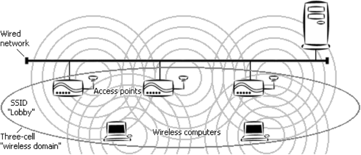
On an infrastructure network, each access point (AP) is set to use a fixed channel, and
stations automatically detect the channel used by the AP that provides the best signal
quality. The
Channel control is therefore disabled when the Network Mode control is set
to
Infrastructure.
An ad-hoc network operates on a fixed channel. To join a given ad-hoc network, you
must select the correct channel from the
Channel control’s drop-down list. The settings
offered in the list depend on the regulations of the country in which the adapter was
purchased.
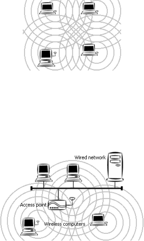
APs with overlapping coverage areas, or different ad-hoc networks operating in the same
area, should use channel settings that are at least four, and preferably five channels apart
(for example, 1, 6, and 11) to avoid interference and obtain the best possible performance.
Power Saving Mode
The Power Saving Mode control is a drop-down list that offers two settings:
Continuous Access Mode and Maximum Power Save.
In Continuous Access mode, your adapter’s receiver is always on.
Maximum Power Save mode is a “doze” mode in which the adapter turns its receiver off
but “wakes up” at fixed intervals to see if any communications are waiting for it. Before
entering this mode, it tells the AP (or, on an ad-hoc network, the current coordinating
station) that it is going to do so. The AP (or coordinating station) will “buffer”
(temporarily store) communications destined for your machine. The adapter stays
“awake” only long enough to check for and receive waiting communications..
4X Mode
The 4X Mode control is a drop-down list that offers two settings: Off and On.
The default setting is
On. When Mode 4x is On, it can therefore provide a higher data
rate (more than 22 Mbps), increased throughput, around two times greater range, than
other 802.11b-compliant adapters. Mode 4x can be used on wireless links to products in
the same family as your adapter.
Security
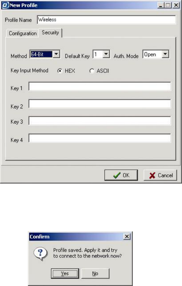
The Security control is a drop-down list at Security panel’s Method for selecting a WEP
setting. Four settings are offered:
Disable, 64-Bit, 128- Bit, and 256-Bit.
The default setting is
Disable. Selecting any other setting enables the WEP key input
controls WEP itself is not enabled in the profile until you complete WEP key input.
If you select
64-Bit, 128- Bit, and 256-Bit, four WEP keys can be used. These keys
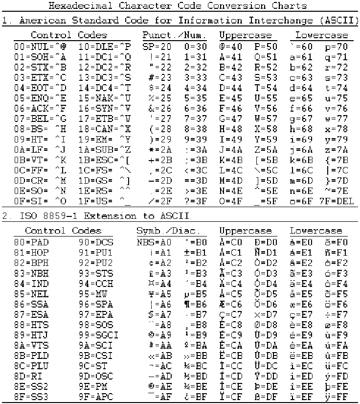
accept “hex” (hexadecimal, that is, base 16) notation or “ASCII” characters. In hex, the
numbers 0 through 9 and the letters A through F are all considered digits (the letters stand
for the values we normally refer to as ten through fifteen). When typing into one of these
keys you must type “0x” first, or your input is considered incomplete. The current key
must be selected here, or you will not be able to connect.
29
The
256-Bit setting can only be used on connections to devices in the same product
family as your adapter.
Auth. Mode
The Auth. Mode (Authentication Mode) control is the first control in the Security panel.
It is a drop-down list offering two settings:
Open, Shared, and Auto.
The setting of this control is ignored when WEP is disabled.
A machine must request permission to join a wireless network. On some networks where
WEP is enabled, a request to join must be WEP-encrypted; on others, it must not.
In Open Authentication mode, requests to join the network are never WEP-encrypted. In
Shared Authentication mode, all requests to join must be WEP-encrypted. The default
setting is
Auto Mode.
Profile Name
The Profile Name control is a text input box for giving the profile a name. Each profile
must have a unique name. A profile name can be any length, but it cannot contain spaces.
The case of any letters you type is preserved. When you are editing an existing profile,
the name appears on a gray background here and cannot be edited.
30
Appendix A: Character Conversion Charts
These charts show both control codes and printable characters. Control codes (including DEL)
have no standard printed representations and are unlikely to appear in plain-text WEP keys; they
are included for completeness only.
Printable characters appear in the punctuation/numbers, symbols/diacritics, uppercase, and
lowercase columns. Each is followed by an equals sign and a numeric value in hexadecimal
notation. Type the value into the appropriate WEP key hex input box. To input the WEP key
Mimsy, for example, you would type 4D, 69, 6D, 73, and 79 into the boxes for the key.
31
Appendix B: Troubleshooting
Problem: Adapter installation appears to have failed.
Solutions:
Make sure the adapter is firmly seated in the CardBus slot.
Uninstall and reinstall the adapter. If the problem persists, uninstall the adapter and install
it in another slot. If possible, try the adapter in another computer to see if the problem is
in the adapter or the computer.
Check to see if there is an IRQ conflict with another device:
1. Open the Start menu, go to Settings, choose Control Panel, open the System
icon, choose
Device Manager, and open the Network adapters entry. If an
exclamation mark [!] appears on the adapter icon, select the icon and choose
Properties.
2. Under
Conflicting device list in the Resources panel of the Properties dialog
box, you will see a device conflict message.
3. Uncheck
Use automatic settings and choose the Change Setting button.
4. Select a new IRQ value. When the message “No conflicts” appears in the
Properties dialog box, close all windows by choosing OK, and then restart the
computer.
Problems: (1) The adapter fails to function. (2) The adapter’s LEDs are both off. (3) The
operating system does not detect the adapter.
Solution: These problems may be caused by unsuccessful installation. If you are sure that the
adapter is firmly seated in a working slot and has not been turned off through the software, we
recommend that you completely uninstall the adapter, the driver, and the utility, and then repeat
the installation procedures described in this manual.
Problem: You cannot join a network that currently appears in the Settings panel’s Site
Survey section.
Solution: Make sure the computer has the same SSID and security settings as the access point or
(in the case of an ad-hoc network) whatever device represents the network in the
Site Survey
listing.
SSID: The SSID is case-sensitive. Every device on a wireless network must use exactly
the same SSID.
Security: If the Site Survey list shows that WEP is disabled on the network, WEP must
be disabled on your machine. If WEP is enabled on the network, it must be enabled with
the same key length and contents on your machine.
In addition, if WEP is enabled, the
Auth. Mode control must be set to either Auto or the
mode used on the network (open authentication or shared authentication).
32
If the network is in ad-hoc mode, in addition to using the correct SSID and security settings, you
must use the channel indicated in the
Site Survey section and set the transmission rate to Auto or
the exact fixed speed used on the network.
Remember that high-speed ad-hoc mode and 256-bit WEP encryption can be used only on
connections to devices in the same product line as your adapter.
Select the connection profile for the network, choose
Details, edit the profile, choose OK, and
choose
Apply to put the new settings into effect.
Problem: An initially good wireless link fails, or the link alternates between good and bad
(the utility icon in the system tray goes from green to red, or constantly alternates between
green and red).
Solutions:
On an ad-hoc network, the link may go up and down for a short while until the network
adjusts to the addition of a new member. A different BSSID may appear in the
Information panel each time the link comes back. The link should quickly stabilize; try
the solutions below only if the problem persists.
The computer may be too far from the access point (or the nearest ad-hoc network
member). If possible, move closer. In some cases, changing the orientation of the antenna
(on one device or both) can help.
There may be interference from a microwave oven, cordless phone, or remote control.
Shut down the interfering device, move it further away, or move away from it. If channel
selection is under your control, setting the access point (or all members of an ad-hoc
network) to use a different channel may solve the problem.
Objects in the vicinity may be blocking or reflecting the signal. Metallic and other high-
density objects affect radio signals the most, but even a tinted or wet window can reduce
signal quality. Signal reflection, even from a remote object, can cause serious “multipath
distortion” (this also causes “ghosts” on television screens). Try a different location
(sometimes a small shift is all that is needed), or, if possible, move objects that may be
affecting reception.
Make sure the access point (or ad-hoc network member) is working correctly. Check all
antennas, connectors, and cables.
Problem: A working, nearby access point does not appear in the Site Survey listing.
Solutions:
Check the range, and check the environment for interference, signal absorption, and
signal reflection (see preceding).
The access point may be set not to broadcast its SSID. If possible, change the setting;
otherwise, contact your dealer to see if an updated driver is available for the adapter.
33
Appendix C: Technical Support
If you encounter a problem that cannot be solved by following the steps in the troubleshooting
section, call your networking equipment supplier for help. Have the following information ready
before you make the call:
Full product name and, if possible, firmware version number
Version numbers of all software products included in the package
Operating system name and version
Network type and configuration, and any recent configuration changes
Actions that led to the situation that prompted the call
LED status and any on-screen messages seen in connection with the problem
If it appears that a return or exchange will be required, you may be asked to provide the serial
number of the product.
Support personnel may ask you to try to reproduce the problem. They may also ask you to run
some simple tests using diagnostic tools included with the system. Proper preparation on your
part can greatly reduce the amount of time needed to solve the problem.
34
Appendix D: Limited Warranty
Hardware
The manufacturer warrants its products to be free of defects in workmanship and materials, under
normal use and service, for a period of 12 months from the date of purchase from the
manufacturer or its authorized reseller, and for the period of time specified in the documentation
supplied with each product.
Should a product fail to be in good working order during the applicable warranty period, the
manufacturer will, at its option and expense, repair or replace it, or deliver to the purchaser an
equivalent product or part at no additional charge except as set forth below. Repair parts and
replacement products are furnished on an exchange basis and will be either reconditioned or new.
All replaced products and parts will become the property of the manufacturer. Any replaced or
repaired product or part has a warranty of ninety (90) days or the remainder of the initial warranty
period, whichever is longer.
The manufacturer shall not be liable under this warranty if its testing and examination disclose
that the alleged defect in the product does not exist or was caused by the purchaser’s or any third
party’s misuse, neglect, improper installation or testing, unauthorized attempt at repair or
modification, or any other cause beyond the range of the intended use, or by accident, fire,
lightning, or other hazard.
Software
Software and documentation materials are supplied “as is,” without warranty as to their
performance, merchantability, or fitness for any particular purpose. However, the media
containing the software is covered by a 90-day warranty that protects the purchaser against failure
within that period.
Limited Warranty Service Procedure
Any product (1) received in error, (2) received in a defective or non-functioning condition, or (3)
exhibiting a defect under normal working conditions, can be returned to the manufacturer by
following these steps:
1. Prepare the following in printed or electronic form:
Dated proof of purchase
Product model number and quantity
Product serial number
Precise reason for return
Your name, address, email address, phone number, and fax number
2. Inform the distributor or retailer.
3. Ship the product back to the distributor/retailer with freight charges prepaid. The
purchaser must pay the cost of shipping from the distributor/retailer to the manufacturer.
Any package sent C.O.D. (Cash On Delivery) will be refused.
35
Charges: Usually, RMA (Returned Material Authorization) items will be returned to the
purchaser via airmail, prepaid by the manufacturer. If any item is returned by another carrier, the
purchaser will pay the difference. A return freight and handling fee will be charged to the
purchaser if the manufacturer determines that the product is not defective or that the damage was
caused by the user.
Warning
The manufacturer is not responsible for the integrity of any data on storage equipment (hard
drives, tape drives, floppy diskettes, etc.). We strongly recommend that our customers back their
data up before sending such equipment in for diagnosis or repair.
Service After Warranty Period
After the warranty period expires, all products can be repaired for a reasonable service charge.
The shipping charges to and from the manufacturer’s facility will be borne by the purchaser.
Return for Credit
In the case of a DOA item (an item that is “dead on arrival”) or a shipping error, a return for
credit will automatically be applied to the purchaser’s account, unless otherwise requested.
Limitation of Liability
All expressed and implied warranties of a product’s merchantability, or of its fitness for a
particular purpose, are limited in duration to the applicable period as set forth in this limited
warranty, and no warranty will be considered valid after its expiration date.
If this product does not function as warranted, your sole remedy shall be repair or replacement as
provided for above. In no case shall the manufacturer be liable for any incidental, consequential,
special, or indirect damages resulting from loss of data, loss of profits, or loss of use, even if the
manufacturer or its authorized distributor/dealer has been advised of the possibility of such
damages, or for any claim by any other party.
36
Appendix E: Specifications
Standards compliance IEEE 802.11b, PCMCIA CardBus (Type II)
Regulatory compliance
USA: FCC Part 15 Class B
EU: ETS 300.328, ETS 300.826, CE Mark
Japan: ARIB STD-T66
Frequency band 2400.0 to 2497.0 MHz (Japan)
2400.0 to 2483.5 MHz (North America and Europe)
2445.0 to 2475.0 MHz (Spain)
2446.5 to 2483.5 MHz (France)
Transmitter power 15 dBm (typical)
Receiver sensitivity* 11 Mbps: -82 dBm (typical)
22 Mbps: -78 dBm (typical)
* Minimum receiver input power level at which a frame error ratio (FER) of less than 8% can be maintained, given a
packet length of 1024 bytes and conditions of 20° to 30° C.
Input power DC 3.3V ±5%
Power consumption 550 mA/3.3V (transmitting), 350 mA/3.3V (receiving)
Data rates 11, 5.5, 2, and 1 Mbps with auto fallback
Special user-selectable 22 Mbps option
RF spreading scheme Direct-sequence spread-spectrum (DSSS)
Encoding and modulation
methods
1 Mbps: Barker sequence + BPSK
2 Mbps: Barker sequence + QPSK
5.5 and 11 Mbps: CCK/PBCC
22 Mbps: PBCC
Security 64- and 128-bit Wired Equivalent Privacy (WEP) encryption
Special user-selectable 256-bit WEP option
Antenna Internal printed diversity type
LED indicators Two: power on/off (green) and wireless activity (orange)
Dimensions (L × W × H) 118 × 54 × 9 mm
Environmental requirements
Operating
humidity:
Operating temperature: 0° to 50° C
Storage temperature: -30° to 70° C
Tested to RH 85% at 40° C (104° F) for 48
hours
Accompanying software Drivers for Microsoft Windows 98/ME (NDIS 5.0), 2000 (NDIS
5.0), and XP (NDIS 5.1); configuration utility with connection
profile management for multiple networks
37
Appendix F: Channels and Regulations
The following table lists the IEEE 802.11b transmission channels and provides important notes
on regulations regarding channel use.
Channel
Start, Center, and
End Frequencies (MHz)
Non-overlapped
Channels
Notes
1
2401 2412 2423 6-14
1
2
2406 2417 2428 7-14
1
3
2411 2422 2433 8-14
1
4
2416 2427 2438 9-14
1
5
2421 2432 2443 10-14
1
6
2426 2437 2448 1, 11-14
1
7
2431 2442 2453 1, 2, 12-14
1
8
2436 2447 2458 1-3, 13, 14
1
9
2441 2452 2463 1-4, 14
1
10
2446 2457 2468 1-5, 14
11
2451 2462 2473 1-6
12
2456 2467 2478 1-7
2
13
2461 2472 2483 1-8
2
14
2473 2484 2495 1-10
3
1.Notes: Not used where the regulations of Spain or France are in effect.
2. Not used where the regulations of Spain or North America are in effect.
3. Used only where the regulations of Japan are in effect.
38
5

Hulp nodig? Stel uw vraag in het forum

Spelregels

Misbruik melden

Gebruikershandleiding.com neemt misbruik van zijn services uitermate serieus. U kunt hieronder aangeven waarom deze vraag ongepast is. Wij controleren de vraag en zonodig wordt deze verwijderd.

Product:

Bijvoorbeeld antisemitische inhoud, racistische inhoud, of materiaal dat gewelddadige fysieke handelingen tot gevolg kan hebben.

Bijvoorbeeld een creditcardnummer, een persoonlijk identificatienummer, of een geheim adres. E-mailadressen en volledige namen worden niet als privégegevens beschouwd.

Spelregels forum

Om tot zinvolle vragen te komen hanteren wij de volgende spelregels:

Belangrijk! Als er een antwoord wordt gegeven op uw vraag, dan is het voor de gever van het antwoord nuttig om te weten als u er wel (of niet) mee geholpen bent! Wij vragen u dus ook te reageren op een antwoord.

Belangrijk! Antwoorden worden ook per e-mail naar abonnees gestuurd. Laat uw emailadres achter op deze site, zodat u op de hoogte blijft. U krijgt dan ook andere vragen en antwoorden te zien.

Abonneren

Abonneer u voor het ontvangen van emails voor uw Draytek Vigor 520 bij:


U ontvangt een email met instructies om u voor één of beide opties in te schrijven.


Ontvang uw handleiding per email

Vul uw emailadres in en ontvang de handleiding van Draytek Vigor 520 in de taal/talen: Engels als bijlage per email.

De handleiding is 1,54 mb groot.


U ontvangt de handleiding per email binnen enkele minuten. Als u geen email heeft ontvangen, dan heeft u waarschijnlijk een verkeerd emailadres ingevuld of is uw mailbox te vol. Daarnaast kan het zijn dat uw internetprovider een maximum heeft aan de grootte per email. Omdat hier een handleiding wordt meegestuurd, kan het voorkomen dat de email groter is dan toegestaan bij uw provider.

Stel vragen via chat aan uw handleiding

Stel uw vraag over deze PDF

Uw handleiding is per email verstuurd. Controleer uw email

Als u niet binnen een kwartier uw email met handleiding ontvangen heeft, kan het zijn dat u een verkeerd emailadres heeft ingevuld of dat uw emailprovider een maximum grootte per email heeft ingesteld die kleiner is dan de grootte van de handleiding.

Er is een email naar u verstuurd om uw inschrijving definitief te maken.

Controleer uw email en volg de aanwijzingen op om uw inschrijving definitief te maken

U heeft geen emailadres opgegeven

Als u de handleiding per email wilt ontvangen, vul dan een geldig emailadres in.

Uw vraag is op deze pagina toegevoegd

Wilt u een email ontvangen bij een antwoord en/of nieuwe vragen? Vul dan hier uw emailadres in.


Info