3
Preamble of DrayTek Vigor2100V series All Rights Reserved
Highlights
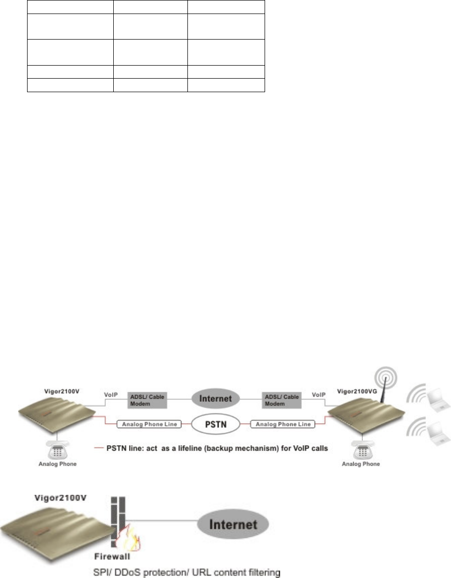
VoIP (Voice over IP)
Connect a regular telephone to make and
receive voice
calls using your existing broadband
connection, leaving your regular line free
Make and receive calls using your regular
phone line (POTS) or via VoIP using the
same telephone handset
Auto-Fallback - Phone switches to PSTN
during power cut SIP, RTP/RTCP protocols
compliance
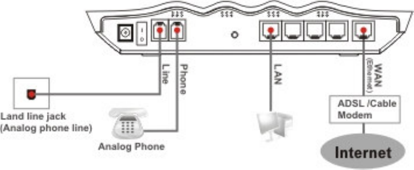
WAN/Internet
One 10/100M Base-TX port with a RJ-45
connector
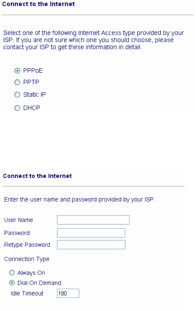
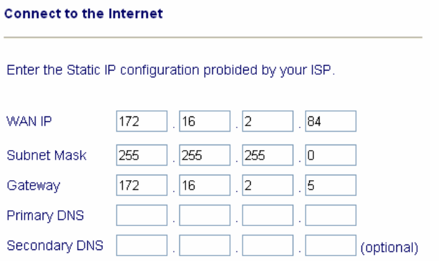
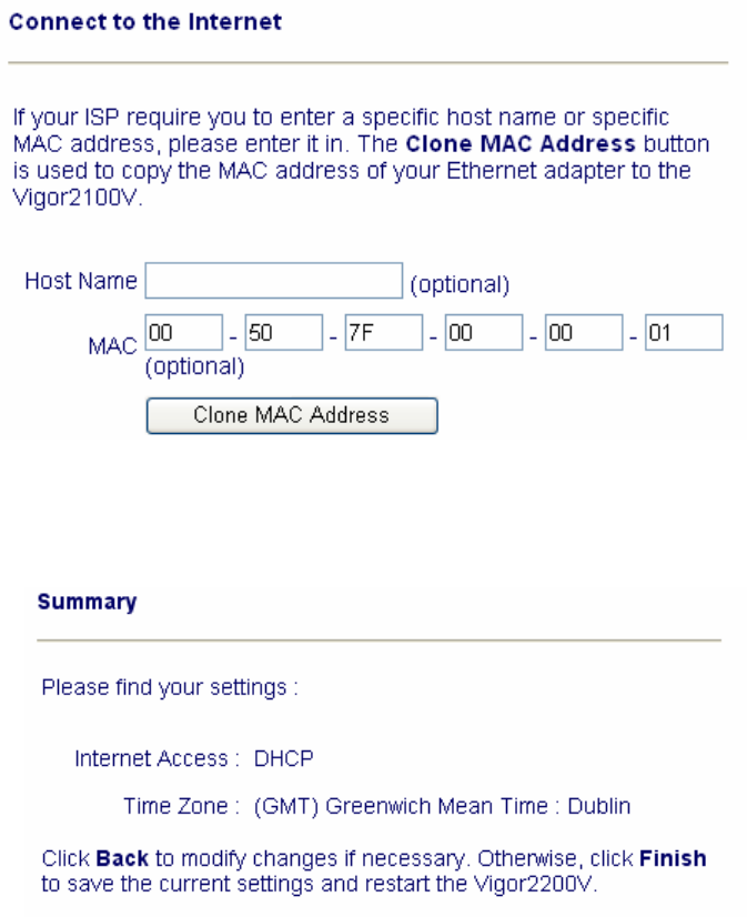
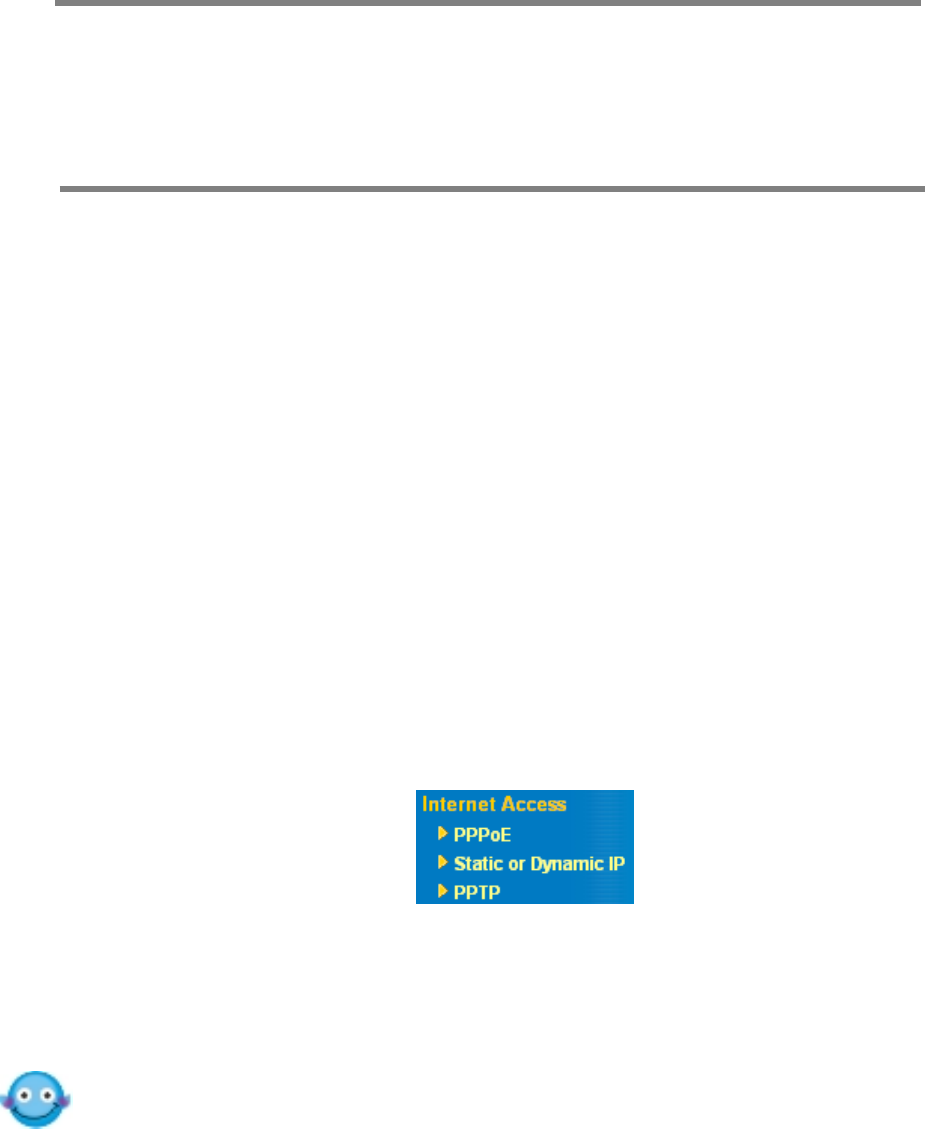
Quick Start Wizard for Internet access
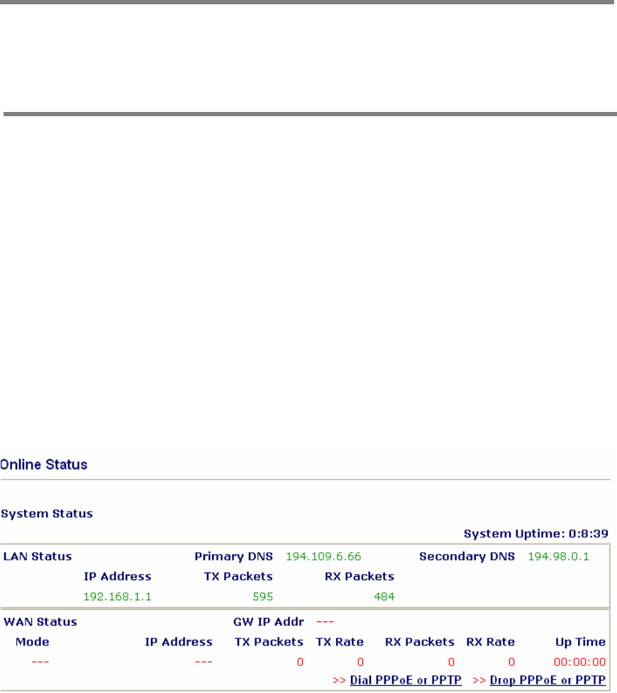
DHCP client for cable service
Static IP address assignment for fixed IP
networks
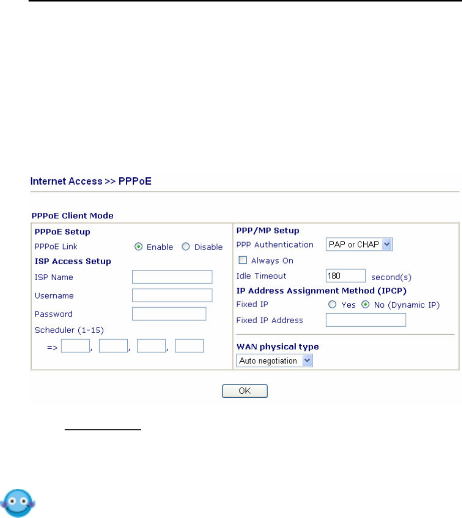
PPPoE client
Firewall Facilities
SPI (Stateful Packet Inspection)
tracks packets and denies unsolicited
incoming data
Selectable DoS/DDoS protection
Flexible URL content filtering
User-configurable packet filtering
NAT/PAT
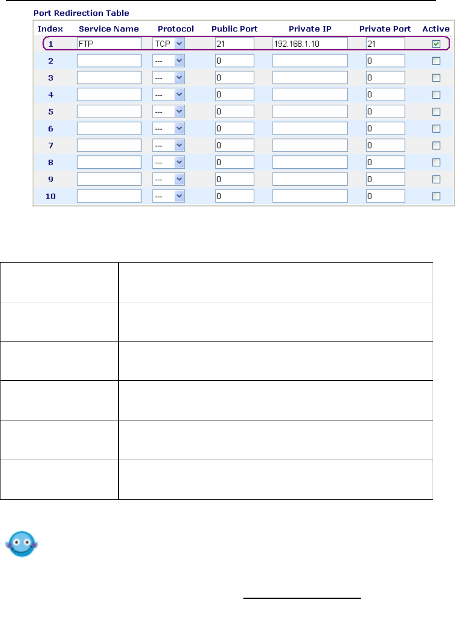
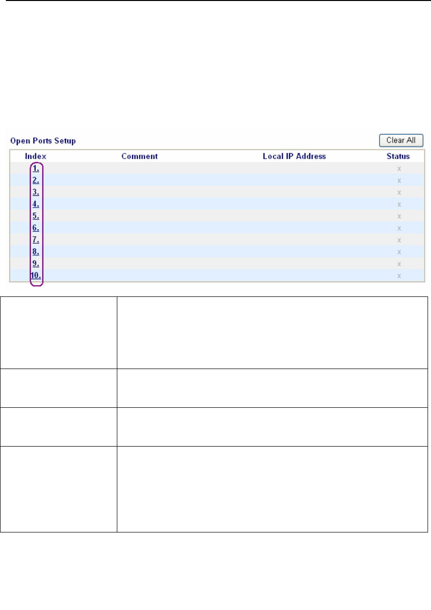
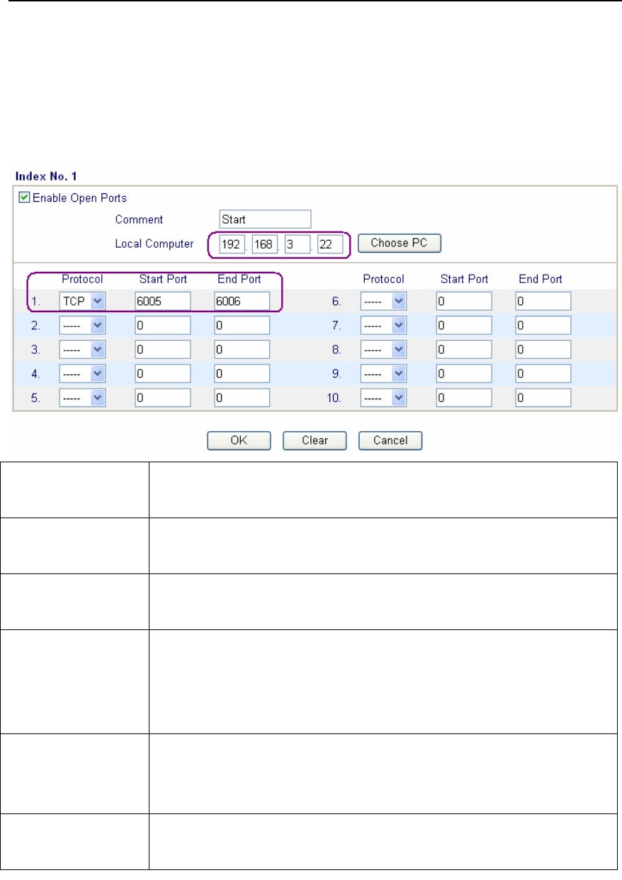
Virtual server via port redirection or open
ports
DMZ host
Supports ALGs (Application Layer
Gateways)
for applications
E-mail Detection
LED flashes to indicate E-mail is waiting on
your mail server (POP3)
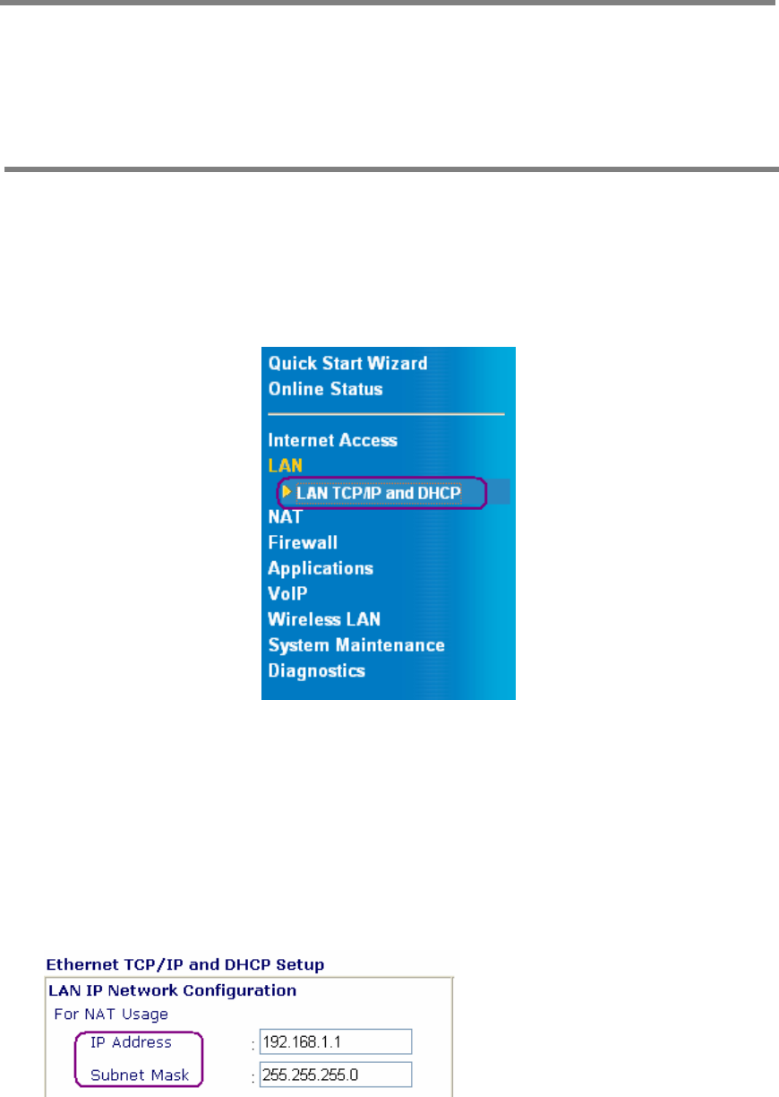
LAN
4-port 10/100M Base-TX Ethernet switch
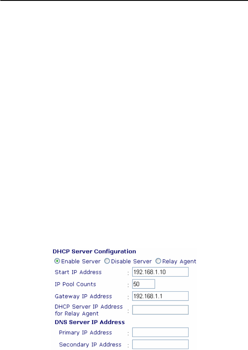
DHCP server for IP assignment (up to 253
users)
DNS cache and proxy
Wireless Access Point (Vigor2100VG only)
Supports 802.11g (54Mbps data rate)
Backward compatible with 802.11b
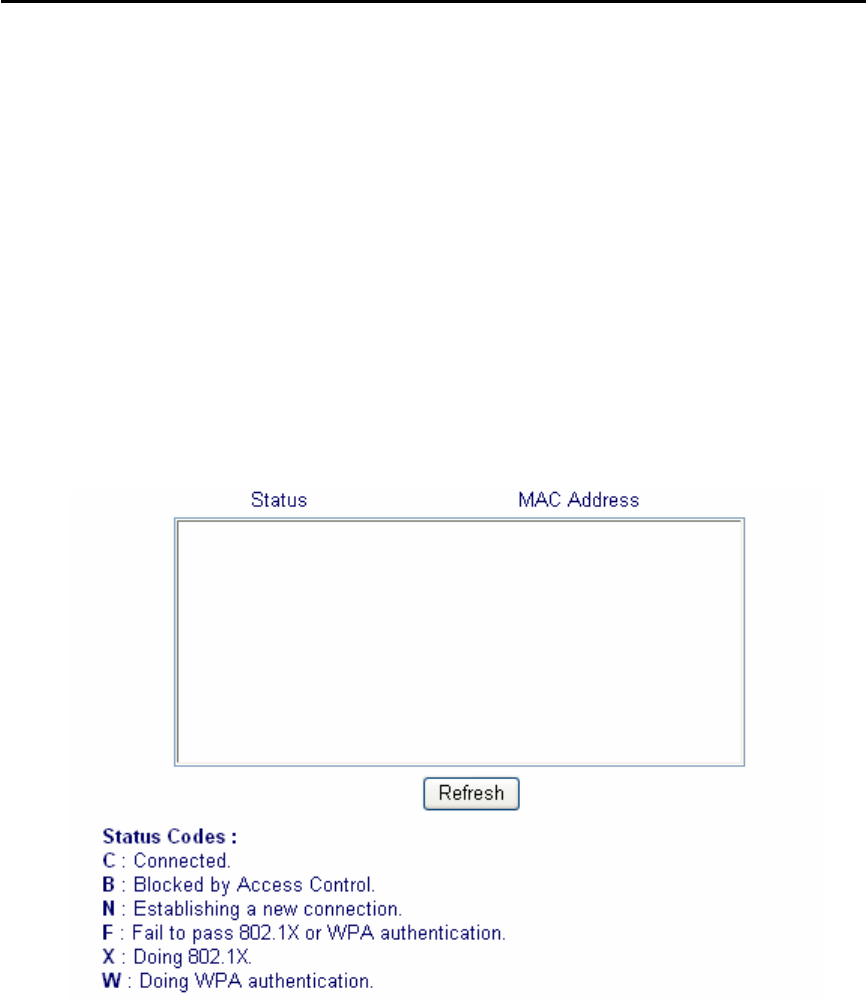
Station List
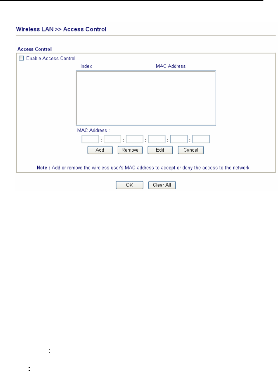
Wireless security:
64/128 bits WEP wireless encryption
WPA/PSK encryption
Client MAC-address locking
SSID stealth
Application Support
Supports VPN pass-through
MSN Messenger V6.2, online gaming, and
other multimedia applications
UPnP protocol enables router control and
enhances access for UPnP -ready
multimedia applications
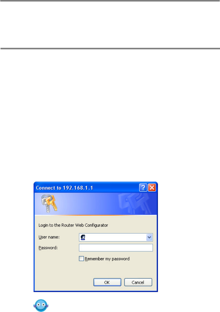
Router Management
Web-based User Interface
Command Line Interface (Telnet)
Telnet Remote Access Support
Built-in Diagnostic Function
Syslog Monitoring