610385
5
Verklein
Vergroot
Pagina terug
1/28
Pagina verder
Type C40 / 110
822 6102 - 00
English
Installation instructions
Absorption Refrigerator for Recreation Vehicles
RM 8400 RM 8401 RM 8405 RM 8500 RM 8501 RM 8505 RM 8550 RM 8551 RM 8555
RMS 8400 RMS 8401 RMS 8405 RMS 8460 RMS 8461 RMS 8465 RMS 8500 RMS 8501
RMS 8505 RMS 8550 RMS 8551 RMS 8555 RML 8550 RML 8551 RML 8555 RMSL 8500
RMSL 8501 RMSL 8505
MBA 06/2010
N 5-1
© Dometic GmbH - 2007-2010 - Subject to change - Printed in Germany
2
Dometic GmbH
In der Steinwiese 16
D-57074 Siegen
www.dometic.com
1.0 General . . . . . . . . . . . . . . . . . . . . . . . . . . . . . . . . . . . . . . . . . . . . . . 4
1.1 Introduction . . . . . . . . . . . . . . . . . . . . . . . . . . . . . . . . . . . . . . . . . . . . . . . . . . . . . . . . . . . . . . . . 4
1.2 Guide to these operating instructions . . . . . . . . . . . . . . . . . . . . . . . . . . . . . . . . . . . . . . . . . . . .4
1.3 Copyright protection . . . . . . . . . . . . . . . . . . . . . . . . . . . . . . . . . . . . . . . . . . . . . . . . . . . . . . . . . 4
1.4 Explanation of symbols used in this manual . . . . . . . . . . . . . . . . . . . . . . . . . . . . . . . . . . . . . . . 4
1.5 Warranty . . . . . . . . . . . . . . . . . . . . . . . . . . . . . . . . . . . . . . . . . . . . . . . . . . . . . . . . . . . . . . . . . . . 5
1.6 Limitation of liability . . . . . . . . . . . . . . . . . . . . . . . . . . . . . . . . . . . . . . . . . . . . . . . . . . . . . . . . . . 5
1.7 Declaration of conformity . . . . . . . . . . . . . . . . . . . . . . . . . . . . . . . . . . . . . . . . . . . . . . . . . . . . . . 5
2.0 Safety instructions . . . . . . . . . . . . . . . . . . . . . . . . . . . . . . . . . . . . . . 6
2.1 Application according to regulations . . . . . . . . . . . . . . . . . . . . . . . . . . . . . . . . . . . . . . . . . . . . .6
2.2 User's responsibility . . . . . . . . . . . . . . . . . . . . . . . . . . . . . . . . . . . . . . . . . . . . . . . . . . . . . . . . . . 6
2.3 Working upon and checking the refrigerator . . . . . . . . . . . . . . . . . . . . . . . . . . . . . . . . . . . . . . . 6
2.4 Operating the refrigerator with gas . . . . . . . . . . . . . . . . . . . . . . . . . . . . . . . . . . . . . . . . . . . . . . 6
3.0 Description of model . . . . . . . . . . . . . . . . . . . . . . . . . . . . . . . . . . . . 7
3.1 Model identification . . . . . . . . . . . . . . . . . . . . . . . . . . . . . . . . . . . . . . . . . . . . . . . . . . . . . . . . . . 7
3.2 Refrigerator rating plate . . . . . . . . . . . . . . . . . . . . . . . . . . . . . . . . . . . . . . . . . . . . . . . . . . . . . . . 7
3.3 Technical data . . . . . . . . . . . . . . . . . . . . . . . . . . . . . . . . . . . . . . . . . . . . . . . . . . . . . . . . . . . . . . 7
4.0 Installation instructions . . . . . . . . . . . . . . . . . . . . . . . . . . . . . . . . . . 9
4.1 Installation . . . . . . . . . . . . . . . . . . . . . . . . . . . . . . . . . . . . . . . . . . . . . . . . . . . . . . . . . . . . . . . . . 9
4.1.1 Side installation . . . . . . . . . . . . . . . . . . . . . . . . . . . . . . . . . . . . . . . . . . . . . . . . . . . . . . . . . . . . . . . . . . . . . . 9
4.1.2 Side installation with floor-roof ventilation . . . . . . . . . . . . . . . . . . . . . . . . . . . . . . . . . . . . . . . . . . . . . . . . . 10
4.1.3 Rear installation . . . . . . . . . . . . . . . . . . . . . . . . . . . . . . . . . . . . . . . . . . . . . . . . . . . . . . . . . . . . . . . . . . . . . 10
4.1.4 Draught-proof installation . . . . . . . . . . . . . . . . . . . . . . . . . . . . . . . . . . . . . . . . . . . . . . . . . . . . . . . . . . . . . . 11
4.2 Ventilation and air extraction . . . . . . . . . . . . . . . . . . . . . . . . . . . . . . . . . . . . . . . . . . . . . . . . . . . 12
4.3 Installing the ventilation system . . . . . . . . . . . . . . . . . . . . . . . . . . . . . . . . . . . . . . . . . . . . . . . . . 13
4.4 Exhaust gas duct and installing the fume flue . . . . . . . . . . . . . . . . . . . . . . . . . . . . . . . . . . . . . . 14
4.5 Installation recess . . . . . . . . . . . . . . . . . . . . . . . . . . . . . . . . . . . . . . . . . . . . . . . . . . . . . . . . . . . . 15
4.5.1 Installation in the recess . . . . . . . . . . . . . . . . . . . . . . . . . . . . . . . . . . . . . . . . . . . . . . . . . . . . . . . . . . . . . . . 15
4.5.2 Recess dimensions . . . . . . . . . . . . . . . . . . . . . . . . . . . . . . . . . . . . . . . . . . . . . . . . . . . . . . . . . . . . . . . . . . . 16
4.6 Securing the refrigerator . . . . . . . . . . . . . . . . . . . . . . . . . . . . . . . . . . . . . . . . . . . . . . . . . . . . . . 17
4.7 Inserting of the decor panel . . . . . . . . . . . . . . . . . . . . . . . . . . . . . . . . . . . . . . . . . . . . . . . . . . . . 17
4.8 Gas installation . . . . . . . . . . . . . . . . . . . . . . . . . . . . . . . . . . . . . . . . . . . . . . . . . . . . . . . . . . . . . . 19
4.9 Electrical installation . . . . . . . . . . . . . . . . . . . . . . . . . . . . . . . . . . . . . . . . . . . . . . . . . . . . . . . . . . 20
4.9.1 Mains connection . . . . . . . . . . . . . . . . . . . . . . . . . . . . . . . . . . . . . . . . . . . . . . . . . . . . . . . . . . . . . . . . . . . . 20
4.9.2 Battery connection . . . . . . . . . . . . . . . . . . . . . . . . . . . . . . . . . . . . . . . . . . . . . . . . . . . . . . . . . . . . . . . . . . . 20
4.9.3 Terminal strip . . . . . . . . . . . . . . . . . . . . . . . . . . . . . . . . . . . . . . . . . . . . . . . . . . . . . . . . . . . . . . . . . . . . . . . 21
4.9.4 D+ and solar connection (only for AES models) . . . . . . . . . . . . . . . . . . . . . . . . . . . . . . . . . . . . . . . . . . . . 21
4.9.5 Wiring diagrams . . . . . . . . . . . . . . . . . . . . . . . . . . . . . . . . . . . . . . . . . . . . . . . . . . . . . . . . . . . . . . . . . . . . . 22
3
Table of contents
4
1.0 General
On installation of the appliance, the technical
and administrative regulations of the country
in which the vehicle will first be used must be
adhered to. Otherwise the refrigerator must be
installed as described in these instructions. In
Europe, for example, gas appliances, cable
routing, installation of gas cylinders, as well as
approval and checking for leaks must comply
with EN 1949 for liquid gas systems in vehi-
cles.
1.1 Introduction
Before you start installing the refrigerator,
please read the installation instructions
carefully.
These instructions provide you with the neces-
sary guidance for the proper installation of
your refrigerator. Observe in particular the
safety instructions. Observation of the
instructions and handling recommendations is
important for dealing with the refrigerator
safely and for protecting you from injury and
the refrigerator from damage. You must under-
stand what you have read before you carry out
a task.
Keep these instructions in a safe place so
they may be referred to at any time.
1.2 Guide to these operating
instructions
General
1.4 Explanation of symbols
used in this manual
Warning notices are identified by symbols. A
supplementary text gives you an explanation
of the degree of danger.
Observe these warning notices rigorously.
You will thus protect yourself and other
people from injury, and the appliance from
damage.
Warning notices
DANGER indicates an imminent hazardous
situation which, if not avoided, could result in
death or serious injury.
DANGER!
WARNING indicates a potentially hazardous
situation which, if not avoided, could result in
death or serious injury
WARNING!
CAUTION indicates a potentially hazardous
situation which, if not avoided, may result in
minor or moderate injury.
CAUTION!
No part of these instructions may be reprodu-
ced, copied or utilised in any other way wit-
hout written authorisation by Dometic GmbH,
Siegen.
The information, texts and illustrations in these
instructions are copyright protected and are
subject to industrial property rights.
1.3 Copyright protection
5
General
All information and guidance in these opera-
ting instructions were prepared after taking
into consideration the applicable standards
and regulations as well as the current state of
the art. Dometic reserves the right to make
changes at any time which are deemed to be
in the interest of improving the product and
safety.
Dometic will assume no liability for damage in
the case of :
non-observation of the operating instructi-
ons
application not in accordance with the
regulations or provisions
use of non-original spare parts
improper modifications and interferences to
the appliance
effect of environmental influences, such as
- temperature fluctuations
- humidity
1.6 Limitation of liability
1.7 Declaration of conformity
Information
INFORMATION gives you supplementary and
useful guidance when dealing with your refrige-
rator.
Environmental Tips
ENVIRONMENTAL TIPS gives you useful gui-
dance for saving energy and disposal of the
appliance.
CAUTION (used without the safety alert sym-
bol) indicates a potentially hazardous situation
which, if not avoided, may result in damage to
the appliance.
CAUTION!
Warranty arrangements are in accordance
with EC Directive 44/1999/CE and the normal
conditions applicable for the country concer-
ned. For warranty or other maintenance, plea-
se contact our customer services department.
Any damage due to improper use is not cover-
ed by the warranty. The warranty does not
cover any modifications to the appliance or
the use of non-original Dometic parts. The
warranty does not apply if the installation and
operating instructions are not adhered to and
no liability shall be entertained.
1.5 Warranty
6
Safety instructions
2.0 Safety instructions
This refrigerator is designed for installation in
recreation vehicles such as caravans or
motorhomes. The appliance has been type-
approval tested for this application in accor-
dance with the EC Gas Directive.
The refrigerator is to be used solely for storing
foodstuffs.
2.1 Application according to
regulations
2.3 Working upon and checking
the refrigerator
Work on gas equipment, exhaust system
and electrical facilities must be carried
out by authorised personnel only.
Substantial damage to property and/or
injury to persons can arise through unpro-
fessional procedures.
WARNING!
Never use an unshielded flame to check
gas bearing parts and pipes for leakage!
There is a danger of fire or explosion.
DANGER!
Never open the absorber cooling unit! It is
under high pressure.
There is a danger of injury!
WARNING!
Anyone operating the refrigerator must be
familiar with the safe handling and understand
the advice in these operating instructions.
2.2 User's responsibility
It is imperative that the operating pressure
corresponds to the data specified on the
rating plate of the appliance. Compare the
operating pressure of the rating plate with the
data specified on the pressure reducing valve
of the liquid gas cylinder.
2.4 Operating the refrigerator
with gas
7
Description of model
3.0 Description of model
3.1 Model identification
The rating plate is to be found on the inside of
the refrigerator. It contains all important details
of the refrigerator. You can read off from this
the model identification, the product number
and the serial number. You will need these
details whenever you contact the customer
service centre or when ordering spare parts.
3.2 Refrigerator rating plate
Fig. 1
Model number
Product number
Serial number
Electrical rating details
Gas pressure
2
2
1
1
3
4
4
5
RM
8 4 0 0
1
5
(S)
(L)
Refrigerator Mobile /
Mobile Absorption Refrigerator
0 = manual energy selection + manual igniti-
on (battery igniter)
1 = manual energy selection, automatic igni-
tion (MES)
5 = automatic and manual energy selection,
automatic ignition (AES)
Model range
4 = Width 486mm
5 = Width 525mm
Depth:
0 = Standard
5 = + 55mm
6 = + 65mm
Stepped cabinet
„Large“
Example :
8
Description of model
Fig. 3Fig. 2
RMS 8xxx
RM 8xxx
H
B
T
RML 8xxx
Fig. 4
Technische Änderungen vorbehalten.
*Durchschnittsverbrauch gemessen bei einer durch-
schnittlichen Umgebungstemperatur von 25°C in
Anlehnung an ISO- Standard.
3.3 Technical data
Model Dimensions Gross capacity
Rating details
Consumption * Net Ignition
H x W x D (mm) with without mains/battery electricity/gas weight Piezo Automat
Depth incl. door freezer compartment over 24hrs
Subject to technical changes.
*Average consumption measured at an average ambient
temperature of 25°C in pursuance of ISO Standard.
RMS 8400
RMS 8401
RMS 8405
RM 8400
RM 8401
RM 8405
RMS 8460
RMS 8461
RMS 8465
RMS 8500
RMS 8501
RMS 8505
RMS 8550
RMS 8551
RMS 8555
RM 8500
RM 8501
RM 8505
RM 8550
RM 8551
RM 8555
RML 8550
RML 8551
RML 8555
RMSL 8550
RMSL 8551
RMSL 8555
821x486x568
821x486x568
821x486x568
821x486x568
821x486x568
821x486x568
821x486x633
821x486x633
821x486x633
821x523x568
821x523x568
821x523x568
821x523x623
821x523x623
821x523x623
821x523x568
821x523x568
821x523x568
821x523x623
821x523x623
821x523x623
1245x525x625
1245x525x625
1245x525x625
1245x525x625
1245x525x625
1245x525x625
80 / 8 lit.
80 / 8 lit.
80 / 8 lit.
90 / 8 lit.
90 / 8 lit.
90 / 8 lit.
90 / 11 lit.
90 / 11 lit.
90 / 11 lit.
90 / 9 lit.
90 / 9 lit.
90 / 9 lit.
103 /12 lit.
103 /12 lit.
103 /12 lit.
100 / 9 lit.
100 / 9 lit.
100 / 9 lit.
115 /12 lit.
115 /12 lit.
115 /12 lit.
179 /33 lit.
179 /33 lit.
179 /33 lit.
145 /28 lit.
145 /28 lit.
145 /28 lit.
85 lit.
85 lit.
85 lit.
95 lit.
95 lit.
95 lit.
96 lit.
96 lit.
96 lit.
96 lit.
96 lit.
96 lit.
110 lit.
110 lit.
110 lit.
106 lit.
106 lit.
106 lit.
122 lit.
122 lit.
122 lit.
189 lit.
189 lit.
189 lit.
155 lit.
155 lit.
155 lit.
125 W / 120 W
125 W / 120 W
125 W / 120 W
135 W / 130 W
135 W / 130 W
135 W / 130 W
125 W / 120 W
125 W / 120 W
125 W / 120 W
125 W / 120 W
125 W / 120 W
125 W / 120 W
125 W / 120 W
125 W / 120 W
125 W / 120 W
135 W / 130 W
135 W / 130 W
135 W / 130 W
135 W / 130 W
135 W / 130 W
135 W / 130 W
190 W / 170 W
190 W / 170 W
190 W / 170 W
190 W / 170 W
190 W / 170 W
190 W / 170 W
ca.2,5 KWh / 270 g
ca.2,5 KWh / 270 g
ca.2,5 KWh / 270 g
ca.2,4 KWh / 270 g
ca.2,4 KWh / 270 g
ca.2,4 KWh / 270 g
ca.2,5 KWh / 270 g
ca.2,5 KWh / 270 g
ca.2,5 KWh / 270 g
ca.2,5 KWh / 270 g
ca.2,5 KWh / 270 g
ca.2,5 KWh / 270 g
ca.2,6 KWh / 270 g
ca.2,6 KWh / 270 g
ca.2,6 KWh / 270 g
ca.2,4 KWh / 270 g
ca.2,4 KWh / 270 g
ca.2,4 KWh / 270 g
ca.2,6 KWh / 270 g
ca.2,6 KWh / 270 g
ca.2,6 KWh / 270 g
ca.3,2 KWh / 380 g
ca.3,2 KWh / 380 g
ca.3,2 KWh / 380 g
ca.3,2 KWh / 380 g
ca.3,2 KWh / 380 g
ca.3,2 KWh / 380 g
25 kg
25 kg
25 kg
27 kg
27 kg
27 kg
26 kg
26 kg
26 kg
26 kg
26 kg
26 kg
27 kg
27 kg
27 kg
28 kg
28 kg
28 kg
30 kg
30 kg
30 kg
45 kg
45 kg
45 kg
40 kg
40 kg
40 kg
RM
S
= stepped cabinet
9
Installation
4.0 Installation instructions
The unit and the exhaust duct system must be
in principle installed so that it is accessible for
maintenance work, can be easily installed and
dismantled and removed from the vehicle wit-
hout great effort.
Installation and connection of the appliance
must comply with the latest technical regulati-
ons, as follows:
The electrical installation must comply
with national and local regulations.
The gas installation must comply with
national and local regulations.
European Standard EN 1949
European Standards EN 60335-1,
EN 60335-2-24, EN 1648-1 , EN 1648-2
The appliance must be installed in such a
way that it is shielded from excessive heat
radiation.
Excessive heat impairs performance and raises
the energy consumption of the refrigerator! !
4.1 Installation
Deviations from these installation instructi-
ons without prior notification of Dometic
result in Dometic GmbH's warranty obligati-
ons becoming void!
The appliance may be installed by authori-
sed personnel only!
WARNING!
(Fig. 6) The air vent grilles offer an unobstructed
dissipation of heat and exhaust gas even when
the door is opened.
4.1.1 Side installation
If the appliance is installed on the same side of
the vehicle as the entrance door, it is desirable
that the door does not cover the refrigerator's
vents. (Fig. 5, Clearance door/ventilation grille at
least 25 mm). Otherwise ventilation could be
impaired which causes a loss in cooling perfor-
mance. Awnings are often placed at the door
side of a caravan. This complicates evacuation
of combustion gases and heat through the ven-
tilation grilles (loss in cooling performance)!
(Fig.5) The air vent grilles are blocked. There
must be a distance between the door and the air
vents of at least 25 mm!
If the door/grille distance is between 25 mm and
45 mm, we recommend installing a Dometic
ventilation kit (
item no. 241 2985 - 00/0
) to
achieve an optimal cooling performance in high
ambient temperatures.
Fig. 5
Fig. 6
Air vent grille not
blocked!
OK!
10
Installation
Fig. 7
floor opening:
at least 50 mm wide,
at least 520 mm long
hot air
condenser
Recommendation:
Roof vent
R500
Proper ventilation of the refrigerator can also be
achieved by lower air intake aperture in the floor
and upper roof exhaust vent (see Fig. 7). A flue
has to be provided between the top edge of the
refrigerator and the roof ventilation which
directs the hot air and the exhausts straight to
the air vent in the roof.
The floor opening must have a cross section of
at least 250 cm² . Protect the opening, e.g. with
a baffle plate and a net, to prevent dirt from
entering the gas burner. Compared to side ven-
tilation, this ventilation method can allow more
dirt to enter the rear area of the refrigerator,
which makes regular maintenance of the gas
burner, at least once a year, necessary.
With this installation method, regular main-
tenance of the gas burner is only possible
once the device has been dismantled. It is
imperative that the refrigerator be installed in
a way to allow easy removal.
We therefore recommend providing an ade-
quate access opening (service flap) for ready
serviceability from the outside.
4.1.2 Side installation with floor-roof
ventilation
Another unfavourable method of rear installation
is to install the air intake and exhaust grilles (Fig.
10) at the side wall of the recreation vehicle. The
air-heat recirculation is very restricted which
means that heat exchangers (condenser, absor-
ber) cannot be adequately cooled. The optional
method of an additional air vent grille installed in
the floor also exhibits an insufficient air flow
duct.
4.1.3 Rear installation
Rear installation often causes an unfavourable
installation arrangement, as ideal ventilation
cannot always be assured (e.g. the lower venti-
lation grille is covered by the bumper or the rear
lights of the vehicle!) (Fig. 8). The maximum coo-
ling performance of the aggregate is actually not
available.
Fig. 8
Fig. 9
Air vent grille not
blocked ! OK!
Air vent grille
blocked !
11
Installation
Fig. 10
The maximum cooling performance is not
available! Do not apply this installation
method, as it does not provide proper ven-
tilation! Please refer to the description in
section 4.2 .
CAUTION!
4.1.4 Draught-proof installation
Refrigerators in motorhomes, caravans or other
vehicles must be installed in a draught-proof
manner (EN 1949). This means that the combu-
stion air for the burner is not taken from the
living space and that exhaust fumes are preven-
ted from entering the living space.
Adequate sealing between the back of the refri-
gerator and the vehicle interior has to be provi-
ded.
Dometic strongly recommends carrying this
out using a flexible seal (in order to simplify later
removal and installation of the unit for mainten-
ance purposes.
By no means use durable sealing com-
pounds, fitting foam or similar material to
realise draught-proof installation of the
refrigerator! Do NOT use any easily inflam-
mable materials for sealing (in particular
silicon sealing compound or similar). Risk
of fire! The device manufacturer's product
liability and warranty shall lapse if such
materials are used.
WARNING!
The lip seals (1) are installed at the bottom and
on each side in the installation recess (Fig. 11-
13). A heat deflector plate (2) is installed in the
installation recess above the refrigerator. Affix
the this plate to the caravan wall, do NOT
attach to the refrigerator !
Insert deflector plate in such a way that the hot
air escapes through the air vent grille into the
open air.
Fig. 12
Fig. 11
Fig. 13
1
1
2
Proposal 1
2
12
In the event of high ambient temperatures,
full performance of the cooling unit can only
be achieved by means of adequate ventilati-
on and extraction.
Ventilation is provided for the unit by means of
two apertures in the caravan wall. Fresh air
enters at the bottom, extracts the heat and exits
through the upper vent grille (chimney effect).
The upper ventilation grille should be positio-
ned as high as possible above the condenser
(A). Install the lower ventilation grille at floor
level of the vehicle, allowing unburnt gas (hea-
vier than air) to escape directly into the open air.
Should this arrangement prove impossible, a
ventilation aperture must be introduced by the
manufacturer of the vehicle into the recess floor
in order to avoid the accumulation of unburnt
gas on the floor (Fig.18).
A correct installation of the refrigerator is essen-
tial for its correct operation, as due to physical
reasons heat builds up at the back of the appli-
ance which must be allowed to escape into the
open air.
4.2 Ventilation and air extraction
of the refrigerator
Installation
The cavity in-between the outer vehicle wall and
refrigerator is completely isolated from the vehi-
cle interior. Intrusion of exhaust fumes into the
living space is prevented. Fumes will escape
through the upper ventilation grille to the outsi-
de.
The draught-proof installation does not require a
special exhaust gas duct to be used. This instal-
lation method allows the use of the same air
vent grille LS200 at the top and at the bottom
without flue duct. .-Nummer :
If a flue duct is nevertheless desirable, incorpo-
rate the LS100 ventilation system with flue duct
into the upper air vent opening. (
For installation,
please refer to "4.4"
)
Deviations require the consent of the manu-
facturer!
Fig. 16
Flue duct
The refrigerator is later pushed into the installa-
tion recess from the front. Ensure that the seals
abut the case evenly.
This installation option facilitates the removal
and installation of the appliance for servicing.
Fig. 14/15
Fasten the sealing lips to a stop bar on the rear
side (1), e.g. by gluing.
1
Proposal 2
13
Correct mounting of the lower ventilation grille
facilitates access to the connections and
functional parts during maintenance.
Fig. 17
ventilation grille LS 100 or LS 200
ventilation grille LS 200
2
1
The ventilation grilles must have an open
cross-section of at least 250cm². This is
achieved by using the Dometic L100 / L 200
absorber ventilation and air extraction system
which has been tested and approved for this
purpose.
Fig. 19
Fig. 20
The LS 100 upper vent system kit consists of
the mounting frame (RS 1640), the air grille
including flue gas duct (AS 1620) and the winter
cover (WA120). The LS 200 lower vent system
kit consists of the mounting frame (RS 1650),
the air grille (AS1 630, but without flue gas duct)
and the winter cover (WA130).
4.3 Installing the ventilation system
LS 100
LS 200
Installation
Fig. 18
ventilation aperture
(d = 20 - 40 mm)
ventilation aperture
1
2
1
2
14
Fig. 21
Fig. 25
Seal the mounting frame
making it waterproof
(
does not apply for
mounting frames with
integral seal
).
1
Fig. 22
Insert frame and screw
into position
2
To install the ventilation grilles, cut two rectan-
gles (451 mm x 156 mm) in the outer wall of the
vehicle (
for position of the cuts, see point 4.2
).
Fig. 23
Insert and lock ventilati-
on grille.
3
Fig. 24
Clip the insert for flue
gas duct in position (
only
for L100 upper ventilati-
on system kit
).
4
Insert winter cover.
5
The exhaust gas duct system must be made in
such a manner as to achieve a complete extrac-
tion of combustion products to the outside of
living space. The duct system must slope in an
upward direction in order to avoid a build-up of
condensate. The type of exhaust gas duct
shown in Fig. 26 allows the side installation of
the winter cover.
4.4 Exhaust gas duct and instal-
ling the fume flue
An installation other than described will
reduce the cooling capacity and jeopardise
the manufacturer's warranty/product liabi-
lity.
CAUTION!
Installing the standard fume flue (Fig. 26)
1. Connect T-piece (E) to adaptor (F) or flue
pipe (K) as required and affix with screw (G).
Ensure that heat baffle (H) is lodged in the cor-
rect position.
2. Insert flue pipe with cover plate (C) through
the appropriate aperture in the upper frame (I)
and connect to T-piece (E). If necessary, shorten
flue pipe (C) to the required length.
3. Insert LS 100 ventilation grille (D) into moun-
ting frame (I) and fasten, using the locking
handle on the left of the grille.
4. Put cap (B) on flue pipe (C).
5. Insert extractor insert (A) into ventilation gril-
le (D).
Installation
15
Fig. 26
4.5.1 Installation in the recess
Note: When installing the appliance ensure
that the door hinges are supported. Figure 28
shows the optimum installation of the refrige-
rator, whereas Fig. 29 shows the minimum
requirement with the maximum clearance bet-
ween installation area and end of hinge. If the
installation is carried out as per Fig. 30, the
hinge is not capable of supporting the possible
load in the door. It is therefore essential that
the maximum clearance of 40 mm not be
exceeded
Fig. 28
Fig. 29
Fig. 30
Ideal fitting
Minimum requirement
Distance greater than 40mm
The refrigerator must be installed draught-proof
in a recess (also refer to Section "4.1.4"). The
measurements of the recess are stated in the
table below. Step A (Fig.31) is only required for
cabinets with a step. Push the appliance far
enough into the recess until the front edge of the
refrigerator casing is aligned with the front of the
recess. Allow a gap of 15-20 mm between the
back wall of the recess and the refrigeration
unit. The floor of the recess must be level, allo-
wing the appliance to be pushed easily into its
correct position. The floor must be substantial
enough to bear the weight of the appliance.
Ensure that the refrigerator is installed level
in the recess.
4.5 Installation recess
CAUTION!
Installation
Model Height H Width B Depth T Height HSt DepthTSt
RMS 8400
RMS 8401
RMS 8405
RM 8400
RM 8401
RM 8405
RMS 8460
RMS 8461
RMS 8465
RMS 8500
RMS 8501
RMS 8505
RMS 8550
RMS 8551
RMS 8555
RM 8500
RM 8501
RM 8505
RM 8550
RM 8551
RM 8555
RML 8550
RML 8551
RML 8555
RMSL 8550
RMSL 8551
RMSL 8555
825 mm
825 mm
825 mm
825 mm
825 mm
825 mm
825 mm
825 mm
825 mm
825 mm
825 mm
825 mm
825 mm
825 mm
825 mm
825 mm
825 mm
825 mm
825 mm
825 mm
825 mm
1249 mm
1249 mm
1249 mm
1249 mm
1249 mm
1249 mm
490 mm
490 mm
490 mm
490 mm
490 mm
490 mm
490 mm
490 mm
490 mm
527 mm
527 mm
527 mm
527 mm
527 mm
527 mm
527 mm
527 mm
527 mm
527 mm
527 mm
527 mm
529 mm
529 mm
529 mm
529 mm
529 mm
529 mm
542 mm
542 mm
542 mm
542 mm
542 mm
542 mm
607 mm
607 mm
607 mm
542 mm
542 mm
542 mm
597 mm
597 mm
597 mm
542 mm
542 mm
542 mm
597 mm
597 mm
597 mm
599 mm
599 mm
599 mm
599 mm
599 mm
599 mm
220 mm
220 mm
220 mm
220 mm
220 mm
220 mm
220 mm
220 mm
220 mm
220 mm
220 mm
220 mm
220 mm
220 mm
220 mm
235 mm
235 mm
235 mm
235 mm
235 mm
235 mm
235 mm
235 mm
235 mm
235 mm
235 mm
235 mm
235 mm
235 mm
235 mm
16
4.5.2 Recess dimensions
Installation
Fig. 31
17
After the refrigerator is put in its final place,
secure the screws into the wall of the recess.
The screws must penetrate the casing of the
refrigerator.
Fig. 32
Fig. 33
In the sidewalls of the refrigerator, there are four
plastic sleeves for securing the refrigerator. The
sidewalls or strips attached for securing the
refrigerator must be prepared to hold the screws
firmly in place even when under increased load
(while the vehicle is moving). Fastening screws
and caps are supplied with the refrigerator.
4.6 Securing the refrigerator
Always insert screws through the sleeves
provided as otherwise components laid in
foam, such as cables etc., could be dama-
ged.
CAUTION!
4.7 Inserting the decor panel
Remove the lateral ledge (1) the door
(ledge is attached, not screwed).
Shift decor panel (2) away from the door
and insert the new decor panel. Re-attach
ledge (1) .
Fig. 34
Model RM 8xxx, RMS 8xxx
2
1
Installation
Decor panel dimensions :
743 +/- 0.5 mm 472 +/- 0.5 mm max. 2.2 mm
Casing width
486 mm
Height Width Thickness
743 +/- 0.5 mm 510,5 +0/- 1 mm max. 2.2
Casing width
523 mm
Height Width Thickness
18
Fig. 35
Model RML 8xxx
1
2
Fig. 38
Fig. 40
Fig. 41
Fig. 39
Model RML 8xxx, frameless decor panel
1
2
3
4
Installation
1.
2.
3.
4.
Decor panel dimensions :
1169,5 +0/-1 mm 507,5 +0/-1 mm max. 1.7 mm
Casing width
525 mm
Height Width Thickness
Fig. 36
Fig. 37
CAUTION!
19
Observe the regulations stated in section
2.1
This refrigerator is provided for installati
on within liquid gas equipment in compli
ance with EN1949 and must be run exclu-
sively on liquid gas (propane, butane) (no
natural gas, town gas).
A fixed, pre-set pressure regulator com-
plying with EN 12864 must be connected
to the liquid gas cylinder.
The pressure regulator must concur with
the operating pressure specified on the
rating plate of the appliance. The opera-
ting pressure corresponds to the standard
pressure of the country of specification
(EN 1949, EN 732).
Only one connection pressure is permissi-
ble for any one vehicle! A plate showing
the permanent, clearly legible notice must
be displayed in full view at the point where
the gas cylinder is installed.
The gas connection to the appliance must
be installed securely and free of stress
using pipe connectors and must be secu-
rely connected to the vehicle (a hose con-
nection is not permissible) (EN 1949).
The gas connection to the appliance is
effected by means of (Ermeto-) olive type
fitting L8, DIN 2353-ST, complying with EN
1949 ( s. figure 42).
After professional installation, a leakage
test as well as a flame test have to be car-
ried out by qualified personnel* in confor-
mity with EN 1949. A test certificate has to
be issued.
* Specialised personnel are accredited experts who are
able, by virtue of their training and knowledge, to vouch for
the correct installation and implementation of the leakage
test.
The refrigerator must be equipped with a
shut-off valve allowing to cut the supply
line. Such a shut-off device must be readi-
ly accessible to the user.
4.8 Gas installation
The gas connection shall be carried out
by specialised personnel* only.
WARNING!
Dometic refrigerators are equipped for a con-
nection pressure of 30 mbar. For connection to
a 50 mbar gas system, use Truma VDR 50/30
medium pressure controller.
Installation
When using LPG gas, please consider that the
burner needs cleaning at shorter intervals due
to the gas combustion method (2 - 3 times per
year recommended).
Fig. 42
SW 14
SW 17
CAUTION!
20 Nm
max
10 Nm
max
20
Fig. 43
The electrical installation must be in
accordance with the national regulations
of the respective countries.
The connection cables must be routed in a
way to prevent contact with hot compo-
nents of the unit/burner or with sharp
edges.
Changes to the internal electrical installa-
tion or the connection of other electrical
components (e.g. external fan) to the
internal wiring of the appliance will render
the e1/ CE admittance as well as any
claims from warranty and product liability
void!
* Specialised personnel are accredited experts who are
able, by virtue of their training and knowledge, to vouch
for the correct installation.
4.9 Electrical installation
The electrical installation shall be carried
out by qualified personnel only.
WARNING!
4.9.1 Mains connection
The power should be supplied by a pro-
perly grounded socket outlet or a groun-
ded non-detachable connection. Where a
socket outlet with mains supply is used,
the outlet must be freely accessible.
Should the connection cable be damaged,
have it replaced by Dometic Customer
Services or by qualified personnel to avoid
hazards.
We recommend leading the power supply via a
board-side fuse protection.
4.9.2 Battery connection
The machine's 12V connection cable is connec-
ted (observing correct polarity) to a terminal
strip. The wiring for the heating element (refer to
A, B wiring diagram connections; connection
cable white/red) must be direct and by the shor-
test possible route to the battery or electric
generator.
Cable cross sections and cable lengths :
Motor
caravan & Caravan (inside)
4 mm
²
(RML 8xxx = 6 mm
²
)< 6 m
6 mm
²
(RML 8xxx = 10 mm
²
)> 6 m
Caravan (outside)
min 2,5 mm
²
(EN1648-1)
2,5mm²
Provide a 16 A fuse to protect on-board 12 V
circuit.
In order to ensure that the 12V power supply is
shut off when stopping the engine (otherwise
the battery would discharge within a few hours),
perform the power supply to the heating ele-
ment (cf. page 22, connection A/B in wiring dia-
gram) in a way to have the 12V supply only live
while the vehicle ignition is switched on.
The connection C/D (interior light, electronics,
cable black / violet) must be permanently provi-
ded by a 12V DC power supply to be protected
by a 2A fuse.
If the appliance is installed in a caravan the
respective leads for the 12V+ and 12V- con-
nections A/B and C/D must not be connec-
ted to each other on the caravan-side (EN
1648-1).
CAUTION!
Installation
21
4.9.3 Terminal block
Connections :
4.9.4 D+ and solar connection (only for
AES models)
D+ - connection:
A = Ground heating element DC
B = Positive connection, heating element DC
C = Ground electronics
D = Positive connection, electronics
D+ = Alternator signal
S+ = AES input signal from solar charge
regulator
AB
D+
S+
CD
-
+
+
-
on the vehicle
on the appliance
Fig. 44
For MES and AES it is compulsory to provide
a permanent 12V DC supply at the terminals
C/D (permanent voltage supply for functional
electronics).
AB
D+
S+
CD
on the vehicle
on the appliance
Fig. 46
In >Automatic Mode< the AES electronic
system automatically selects the most efficient
energy supply. In automatic mode the electronic
system uses the D+ signal (dynamo +) of the
alternator to detect 12V DC. 12V DC operation
is selected only while the engine is running in
order to prevent battery discharge.
S+ - connection:
12V DC energy can be optionally achieved by
mounting solar equipment to the vehicle. The
solar power equipment must be provided with a
solar charging controller with AES output (ade-
quate charging controllers available in selected
stores). The "S+ connection (Solar +) must be
connected to the respective terminal of the solar
charging controller (AES output). The electronic
system uses the S+ signal of the solar charging
controller to detect solar 12V DC.
Cable cross-sectional areas:
There are no particularly high current flows via
the D+ and S+ connection; therefore no particu-
larly large cross-section is required for these
connections (approx. 1mm² is sufficient).
D+
S+
on the vehicle
on the appliance
Fig. 45
Installation
22
Fig. 43
Wiring diagram RM8xx0 :
4.9.5 Wiring diagrams
Installation
23
Wiring diagram RM8xx1 :
Fig. 47
For MES and AES it is compulsory to provide
a permanent 12V DC supply at the terminals
C/D (permanent voltage supply for functional
electronics).
Installation
24
Wiring diagram RM8xx5 :
Fig. 48
For MES and AES it is compulsory to provide
a permanent 12V DC supply at the terminals
C/D (permanent voltage supply for functional
electronics).
Installation
25
Installation
26
27
28
www.dometic.com
5

Hulp nodig? Stel uw vraag in het forum

Spelregels
1

Forum

Dometic-RMS-8550
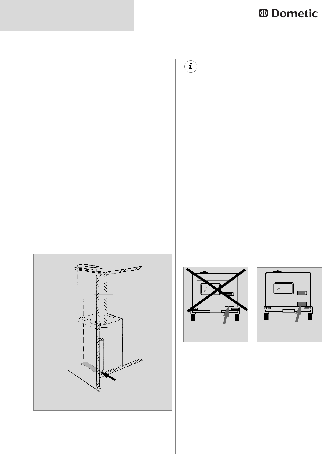
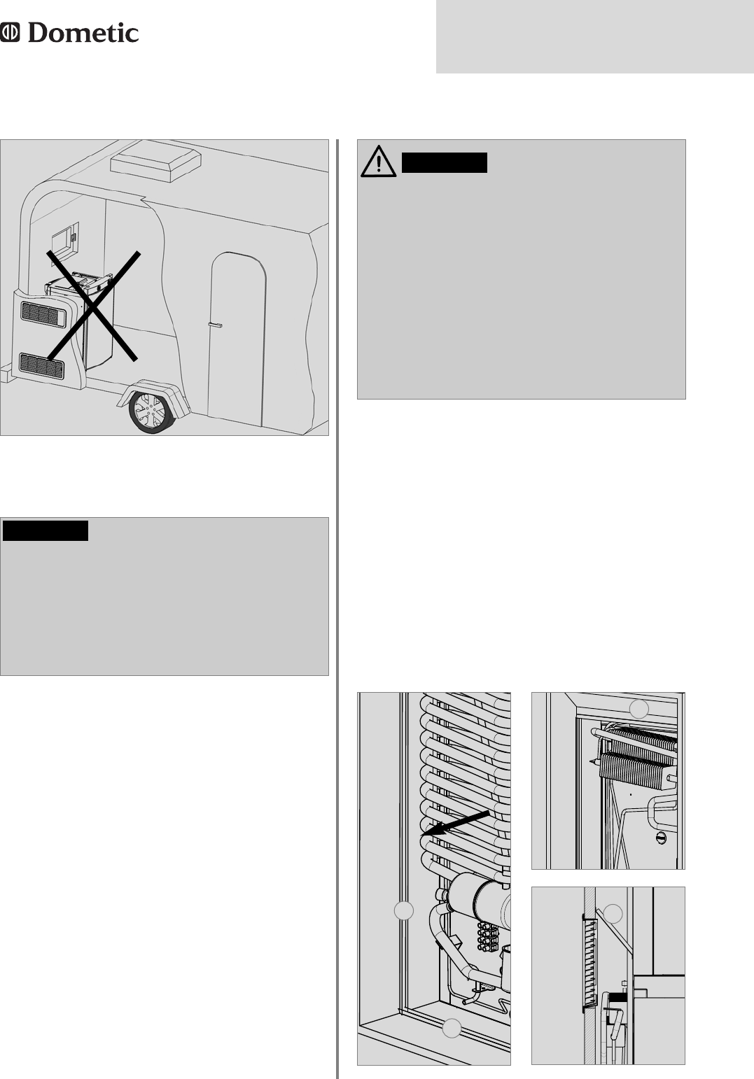
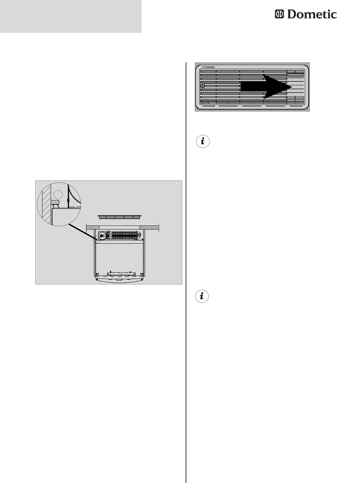
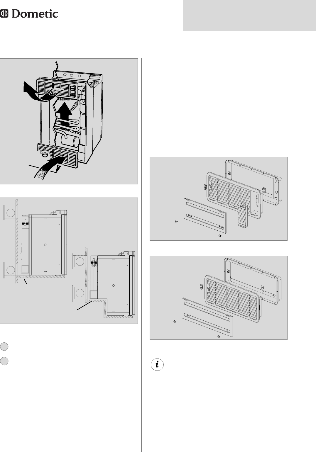
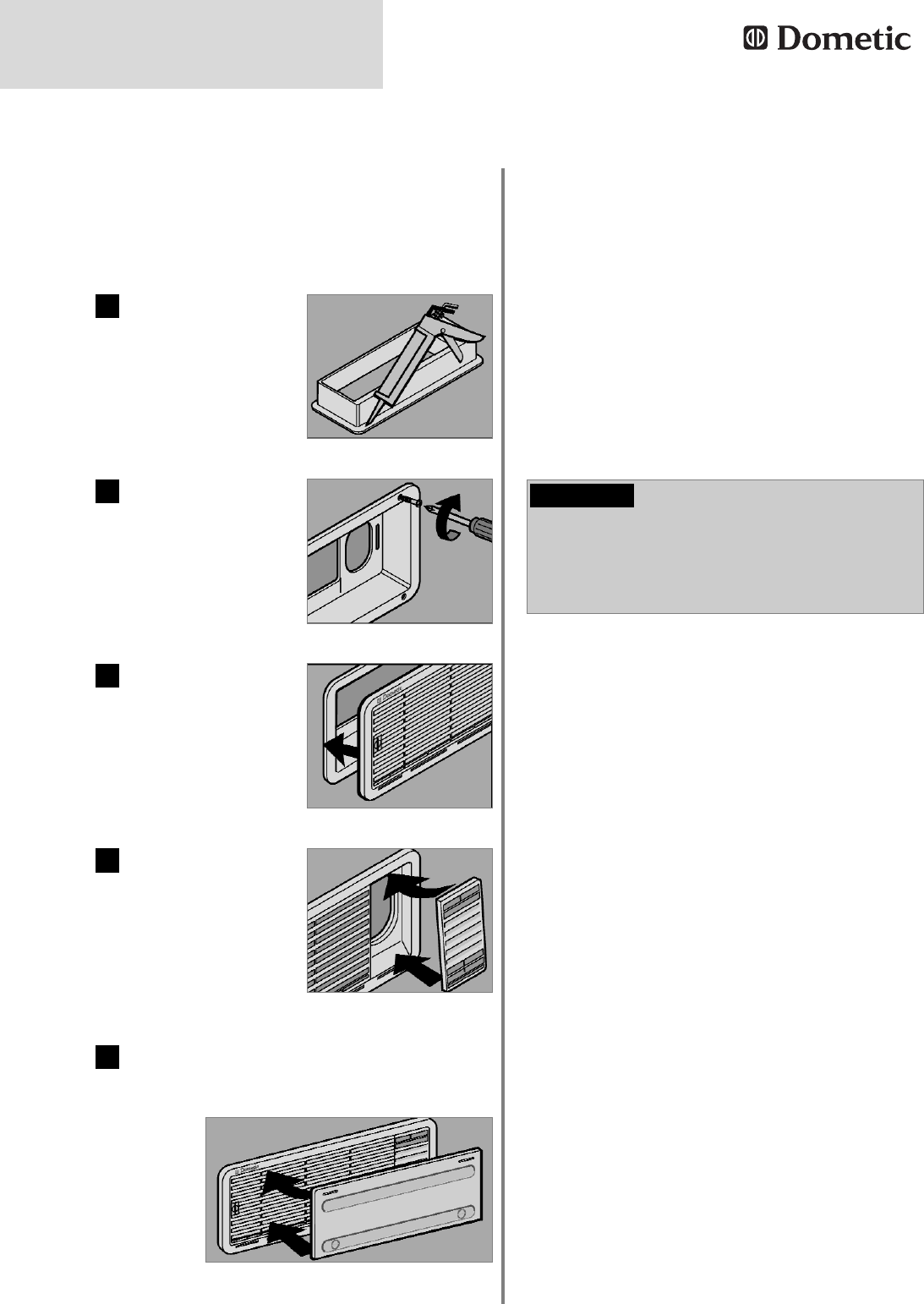
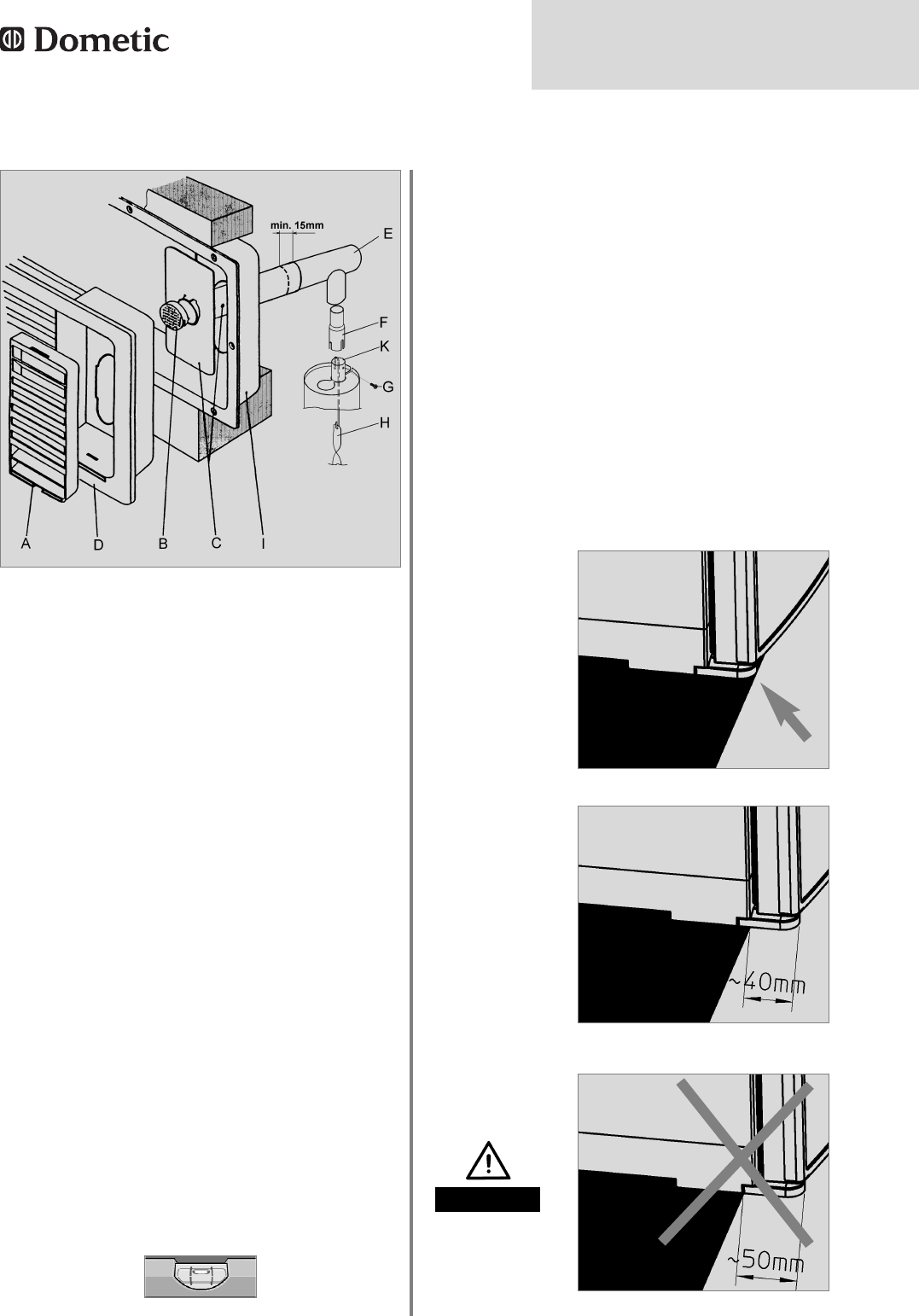
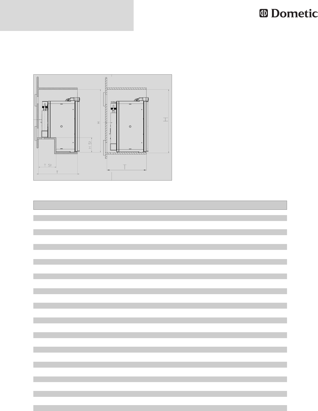
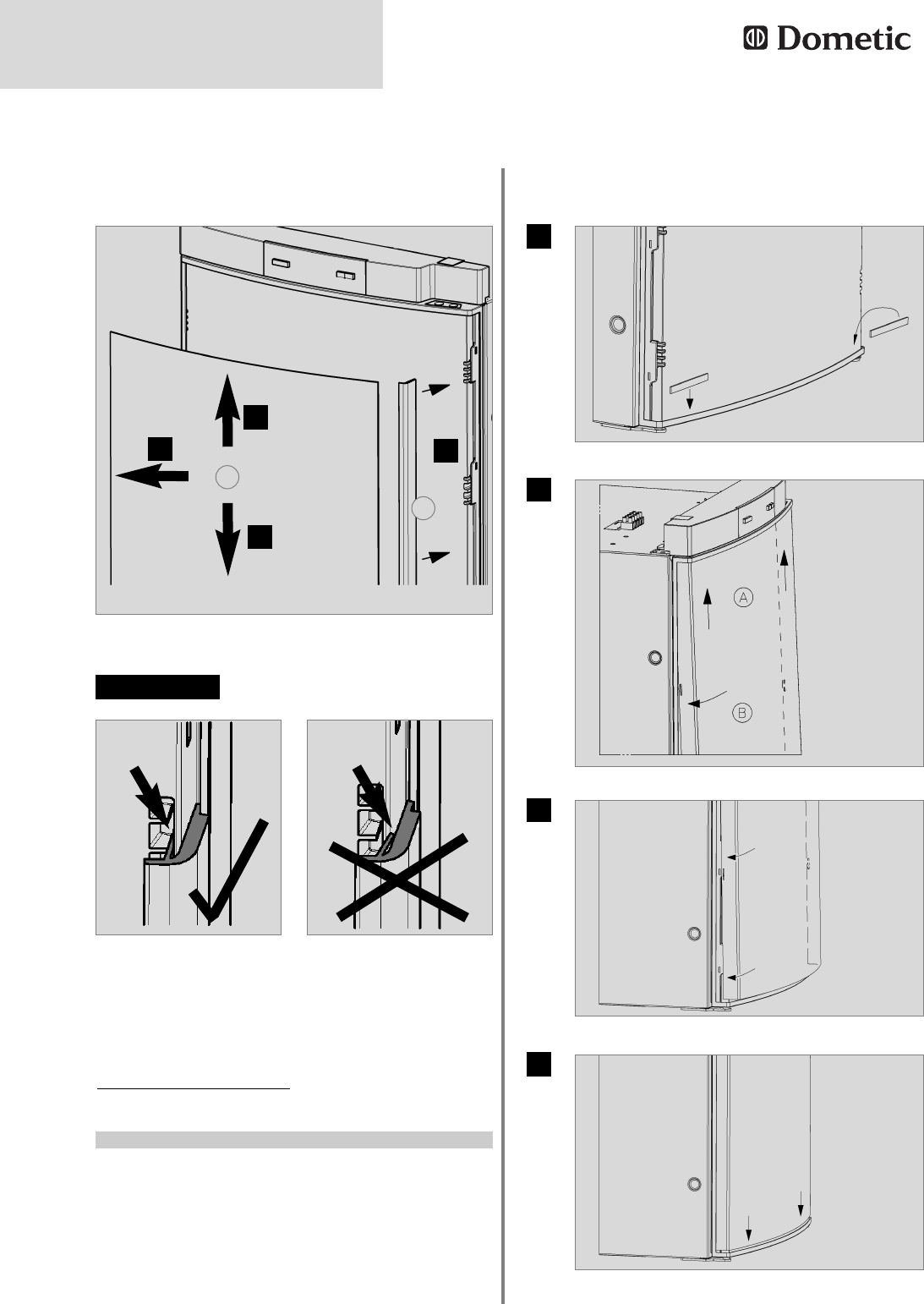
  • Wij hebben een caravan koelkast type RMS 8550 met vriesvak. In vriesvak vriest het niet, wat is het probleem. Koelkast is 7 jaar oud. Gesteld op 28-4-2024 om 19:11

    Reageer op deze vraag Misbruik melden
  • Hoe kunnen aan de achterkant caravan bij gas toevoer. zien niet of hij goed brand.Hoe maken we het open Gesteld op 31-7-2019 om 14:14

    Reageer op deze vraag Misbruik melden
  • Onze koelkast doet het na 1 dag warm weer niet meer. En nu? Gesteld op 24-7-2019 om 09:27

    Reageer op deze vraag Misbruik melden
    • Is dit een caravan/camper koelkast? probeer eens op gas.
      Werkt hij wel op gas dan is het staafelementje defect, kost ongeveer euro 80,00 Geantwoord op 24-7-2019 om 11:33

      Waardeer dit antwoord Misbruik melden
  • Wij hebben vorig jaar een nieuwe Knaus 420 qd silverselection aangeschaft, Helaas koelt de koelkast niet achter de auto, terwijl de koelkast van onze vorige caravan, een Fendt 450 qb wel achter de auto koelde. Heel vervelend. Nu las ik in het instructieboekje van de caravan : let op! koelkast koelt niet achter auto,
    Dat is buitengewoon storend, zeker als je een grote reis wil maken. Is hier een oplossing voor. Op gas koelen is geen optie. Een koelkast hoort toch achter de auto te koelen,,,,, Gesteld op 6-6-2019 om 21:58

    Reageer op deze vraag Misbruik melden
    • Hallo,
      Wij hebben dezelfde koelkast in de Knaus Silver Selection. De koelkast werkt onderweg alleen met een geschakelde stroomdraad. (geeft alleen spanning als de motor draait, schakelt dan aan, en uit als de motor niet draait) Die geschakelde stroomdraad zit meestel op de 13 polige stekker aan de trekhaak. Zoniet dan moet je dat creëren. Succes.
      Groeten,
      Cees
      Geantwoord op 10-6-2019 om 09:30

      Waardeer dit antwoord (1) Misbruik melden
  • Beste Cees,

    Hartelijk dank voor je snelle reactie. Helaas komen wij hier niet verder mee. Geschakelde stroomdraad op 13 is ok. Alleen levert Knaus caravans af (waarschijnlijk sinds 2018) die niet achter de auto koelen. Dat staat duidelijk in het instructieboekje van Knaus. Van welk jaar is jullie Knaus?

    Groet, Bregje Geantwoord op 11-6-2019 om 22:22

    Waardeer dit antwoord (1) Misbruik melden
  • Hoi,
    Dit vind ik heel apart.
    Onze caravan is van 2017.
    Nog een optie is als de koelkast wel geschikt is voor 12V, een aparte stroomdraad(plusdraad) naar de stekker van de trekhaak door te trekken. Wel een zwaardere draad gebruiken anders wordt hij te warm. Ben benieuwd.
    groeten Cees. Geantwoord op 12-6-2019 om 11:05

    Waardeer dit antwoord Misbruik melden
  • In onze Fendt caravan zit koelkast Dometic model RMS 8550 type 40/110
    Nu doet het 230 V en 12V gedeelte het niet.
    Werkt wel op gas.
    Wie heeft de oplossing?? Gesteld op 24-9-2018 om 18:48

    Reageer op deze vraag Misbruik melden
    • Hallo je kunt misschien met een multi-meter
      De termostaat door meten of het element als het element kapot is is dat gemakkelijk te vervangen je kunt deze gemakkelijk op verschillende sites bestellen Geantwoord op 24-9-2018 om 20:19

      Waardeer dit antwoord Misbruik melden
  • Waar element te bestellen? is deze makkelijk te vervangen? Zit deze misschien achter onderste buitenrooster? Geantwoord op 25-9-2018 om 16:01

    Waardeer dit antwoord Misbruik melden
  • Deze kun je bestellen bij bijvoorbeeld de Wit in Schijndel .Het element zit in de zilverkleurige bus achter het rooster door de zilvere mantel te verwijderen kun je het element er uit halen succes. Geantwoord op 25-9-2018 om 20:26

    Waardeer dit antwoord Misbruik melden
  • Bedankt voor de informatie Geantwoord op 25-9-2018 om 23:59

    Waardeer dit antwoord Misbruik melden
  • Draaiknop temperatuurinstelling staat niet in handleiding.hoe stel je de temperatuur in Gesteld op 20-6-2017 om 19:48

    Reageer op deze vraag Misbruik melden
6

Misbruik melden

Gebruikershandleiding.com neemt misbruik van zijn services uitermate serieus. U kunt hieronder aangeven waarom deze vraag ongepast is. Wij controleren de vraag en zonodig wordt deze verwijderd.

Product:

Bijvoorbeeld antisemitische inhoud, racistische inhoud, of materiaal dat gewelddadige fysieke handelingen tot gevolg kan hebben.

Bijvoorbeeld een creditcardnummer, een persoonlijk identificatienummer, of een geheim adres. E-mailadressen en volledige namen worden niet als privégegevens beschouwd.

Spelregels forum

Om tot zinvolle vragen te komen hanteren wij de volgende spelregels:

Belangrijk! Als er een antwoord wordt gegeven op uw vraag, dan is het voor de gever van het antwoord nuttig om te weten als u er wel (of niet) mee geholpen bent! Wij vragen u dus ook te reageren op een antwoord.

Belangrijk! Antwoorden worden ook per e-mail naar abonnees gestuurd. Laat uw emailadres achter op deze site, zodat u op de hoogte blijft. U krijgt dan ook andere vragen en antwoorden te zien.

Abonneren

Abonneer u voor het ontvangen van emails voor uw Dometic RMS 8550 bij:


U ontvangt een email met instructies om u voor één of beide opties in te schrijven.


Ontvang uw handleiding per email

Vul uw emailadres in en ontvang de handleiding van Dometic RMS 8550 in de taal/talen: Engels als bijlage per email.

De handleiding is 0,96 mb groot.


U ontvangt de handleiding per email binnen enkele minuten. Als u geen email heeft ontvangen, dan heeft u waarschijnlijk een verkeerd emailadres ingevuld of is uw mailbox te vol. Daarnaast kan het zijn dat uw internetprovider een maximum heeft aan de grootte per email. Omdat hier een handleiding wordt meegestuurd, kan het voorkomen dat de email groter is dan toegestaan bij uw provider.

Stel vragen via chat aan uw handleiding

Stel uw vraag over deze PDF

Andere handleiding(en) van Dometic RMS 8550

Dometic RMS 8550 Installatiehandleiding - Nederlands, Français - 72 pagina's

Dometic RMS 8550 Gebruiksaanwijzing - Alle talen - 323 pagina's


Uw handleiding is per email verstuurd. Controleer uw email

Als u niet binnen een kwartier uw email met handleiding ontvangen heeft, kan het zijn dat u een verkeerd emailadres heeft ingevuld of dat uw emailprovider een maximum grootte per email heeft ingesteld die kleiner is dan de grootte van de handleiding.

Er is een email naar u verstuurd om uw inschrijving definitief te maken.

Controleer uw email en volg de aanwijzingen op om uw inschrijving definitief te maken

U heeft geen emailadres opgegeven

Als u de handleiding per email wilt ontvangen, vul dan een geldig emailadres in.

Uw vraag is op deze pagina toegevoegd

Wilt u een email ontvangen bij een antwoord en/of nieuwe vragen? Vul dan hier uw emailadres in.


Info