507664
3
Verklein
Vergroot
Pagina terug
1/44
Pagina verder
CS-246.4C
Original Instruction Manual
Instructions d’emploi d’origine
Originalbetriebsanleitung
Manuale di istruzioni originale
Originele gebruiksaanwijzing
Instrucciones de manejo originales
Instruções de serviço original
Original brugsanvisning
Πρωτότυπο εγχειρίδιο οδηγιών
Warning:
Read this instruction manual carefully before putting the Multi Function Power Head into operation and strictly observe the safety regulations!
Save instruction manual for future reference.
Avertissement :
Veuillez lire attentivement ce mode d’emploi avant d’utiliser l’outil multi-fonctions et respectez strictement les consignes de sécurité !
Conservez ce mode d’emploi pour vous y reporter ultérieurement.
Warnung:
Lesen Sie vor Verwendung des Multifunktions-Antriebes diese Bedienungsanleitung aufmerksam durch und halten Sie die Sicherheitsregeln strikt ein!
Bewahren Sie die Anweisungen zum späteren Nachschlagen auf.
Avvertenza:
Leggere attentamente il presente manuale di istruzioni prima di mettere in funzione l’utensile multifunzione a benzina e rispettare scrupolosamente le norme
per la sicurezza.
Conservare il manuale di istruzioni per farvi riferimento in futuro.
Waarschuwing:
Lees deze gebruiksaanwijzing aandachtig door voordat u het multifunctionele aandrijfsysteem in gebruik neemt en houdt u te allen tijde aan de
veiligheidsinstructies!
Bewaar de gebruiksaanwijzing om deze in de toekomst te kunnen raadplegen.
Advertencia:
Lea atentamente este manual de instrucciones antes de utilizar el multifuncional y cumpla estrictamente la normativa de seguridad.
Guarde el manual de instrucciones para futuras consultas.
Aviso:
Leia cuidadosamente este manual de instruções antes de utilizar a Multifuncional a Gasolina e cumpra todas as normas de segurança!
Guarde o manual de instruções para referência futura.
Advarsel:
Læs denne brugsanvisning omhyggeligt igennem inden du anvender det multifunktionelle værktøjshoved og overhold sikkerhedsbestemmelserne til mindste
detalje!
Gem brugsanvisningen, så du har den til fremtidig brug.
Προειδοποιηση:
Πριν θέσετε σε λειτουργία τη Βενζινοκίνητη Κεφαλή Πολλαπλών Χρήσεων διαβάσετε προσεχτικά το εγχειρίδιο οδηγιών και εφαρμόσετε αυστηρά τους
κανονισμούς ασφαλείας!
Φυλάξτε το εγχειρίδιο οδηγιών για μελλοντική αναφορά.
2
Thank you very much for purchasing the DOLMAR Multi Function Power Head.
We are pleased to recommend to you the DOLMAR Multi Function Power
Head which is the result of a long development programme and many years of
knowledge and experience.
Please read this booklet which refers in detail to the various points that will
demonstrate its outstanding performance. This will assist you to obtain the best
possible result from your DOLMAR Multi Function Power Head.
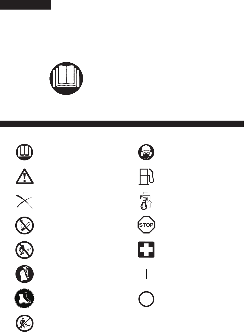
You will note the following symbols when reading the instructions manual.
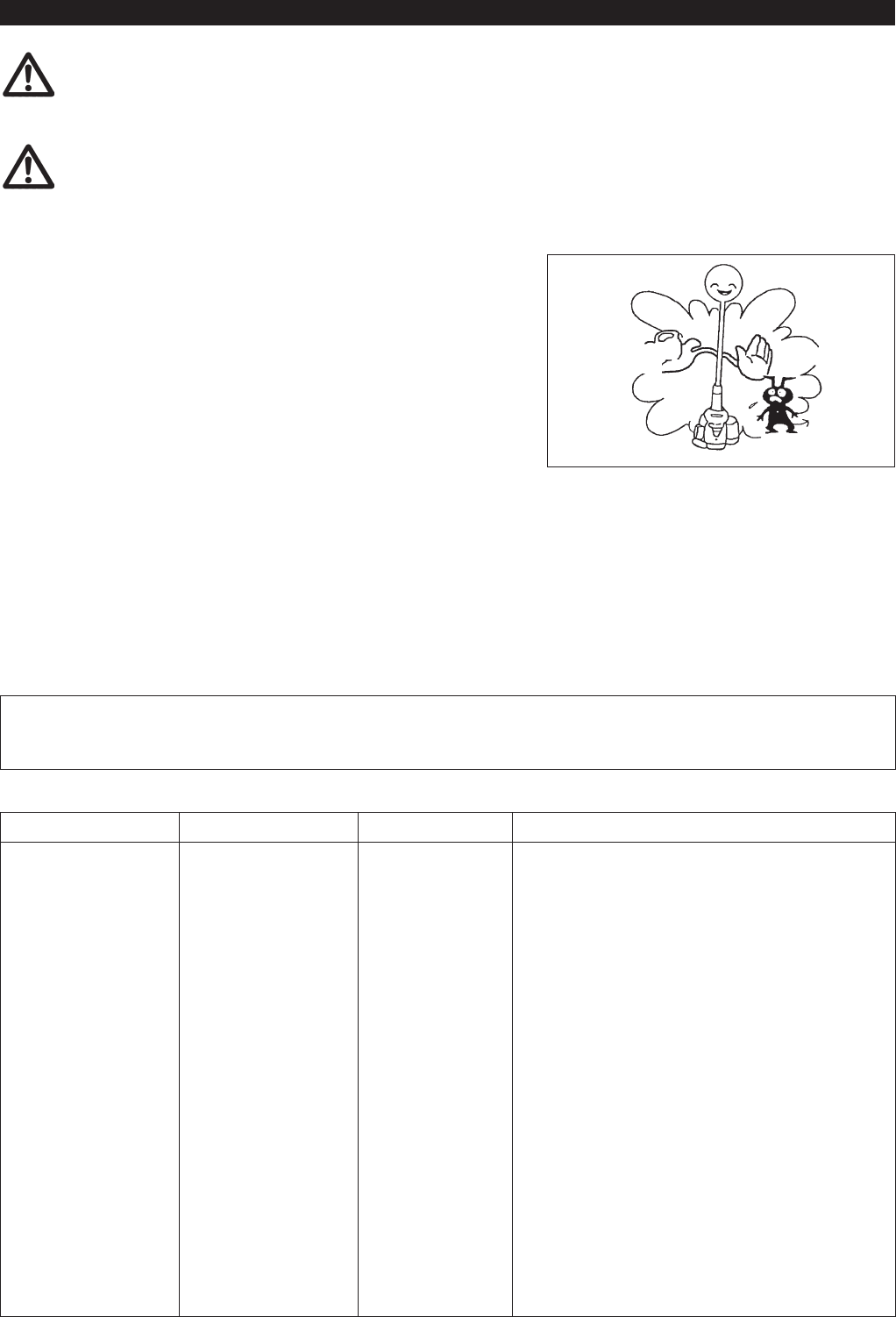
Read instruction manual and follow the
warnings and safety precautions!
Wear protective helmet, eye and ear
protection!
Take particular care and attention! Fuel (Gasoline)
Forbidden! Engine-manual start
No smoking! Emergency stop
No open ame! First aid
Protective gloves must be worn! ON/START
Wear sturdy boots with nonslip soles.
Steeltoed safety boots are recommended!
OFF/STOP
Keep the area of operation clear of all
persons and pets!
SYMBOLS
English
(Original instructions)
Table of Contents Page
Symbols .........................................................................2
Safety instructions .........................................................3
Technical data................................................................7
Approved attachments...................................................8
Designation of parts.......................................................9
Mounting of handle ......................................................10
Mounting attachment ...................................................10
Disassembling .............................................................11
Before start of operation ..............................................12
Correct handling of machine........................................14
Points in operation and how to stop ............................14
Servicing instructions...................................................17
Storage ........................................................................20
3
General instructions
To ensure correct operation, user has to read this instruction manual to make -
himself familiar with the handling of the Multi Function Power Head. Users
insufciently informed will risk danger to themselves as well as others due to
improper handling.
It is recommended only to lend the Multi Function Power Head to people who -
have proven to be experienced with Multi Function Power Heads.
Always hand over the instruction manual.
First users should ask the dealer for basic instructions to familiarize oneself -
with the handling of an engine powered cutter.
Children and young persons aged under 18 years must not be allowed to -
operate the Multi Function Power Head. Persons over the age of 16 years
may however use the device for the purpose of being trained only whilst
under supervision of a qualied trainer.
Use Multi Function Power Heads with the utmost care and attention. -
Operate the Multi Function Power Head only if you are in good physical -
condition. Perform all work calmly and carefully. The user has to accept
liability for others.
Never use the Multi Function Power Head after consumption of alcohol or -
drugs, or if feeling tired or ill.
National regulation can restrict the use of the machine. -
Personal protective equipment
The clothing worn should be functional and appropriate, i.e. it should be tight- -
tting but not cause hindrance. Do not wear either jewelry or clothing which
could become entangled with bushes or shrubs.
In order to avoid either head-, eye-, hand-or foot injuries as well as to protect -
your hearing the following protective equipment and protective clothing must
be used during operation of the Multi Function Power Head.
Always wear a helmet where there is a risk of falling objects. The protective -
helmet (1) is to be checked at regular intervals for damage and is to be
replaced at the latest after 5 years. Use only approved protective helmets.
The visor (2) of the helmet (or alternatively goggles) protects the face from -
ying debris and stones. During operation of the Multi Function Power Head
always wear goggles, or a visor to prevent eye injuries.
Wear adequate noise protection equipment to avoid hearing impairment (ear -
muffs (3), ear plugs etc.).
The work overalls (4) protect against ying stones and debris. -
We strongly recommend that the user wears work overalls.
Special gloves (5) made of thick leather are part of the prescribed equipment -
and must always be worn during operation of the Multi Function Power Head.
When using the Multi Function Power Head, always wear sturdy shoes (6) -
with a non-slip sole. This protects against injuries and ensures a good footing.
Starting up the Multi Function Power Head
Please make sure that there are no children or other people, also pay -
attention to any animals in the working vicinity.
Make sure that the attachment is attached in place, the control lever for easy -
action and check for proper functioning of the lock-off lever.
Motion of the attachment during idling speed is not allowed. Check with your -
dealer for adjustment if in doubt. Check for clean and dry handles and test
the function of the start/stop switch.
15 Meters
Diagrammatic gure
SAFETY INSTRUCTIONS
Intended use of the machine
This multi function power head is intended for driving an approved attachment
listed in this instruction manual. Never use the machine for the other purpose.
4
Start the Multi Function Power Head only in accordance with the instructions.
Do not use any other methods for starting the engine! -
Use the Multi Function Power Head and the tools only for such applications -
as specied.
Only start the Multi Function Power Head engine, after the entire assembly -
is done. Operation of the device is only permitted after all the appropriate
accessories are attached!
Before starting make sure that the attachment has no contact with hard -
objects such as branches, stones etc. as the attachment will revolve when
starting.
The engine is to be switched off immediately in case of any engine problems. -
Should the attachment hit stones or other hard objects, immediately switch off -
the engine and inspect the attachment.
Operate the Multi Function Power Head only with the shoulder strap attached -
which is to be suitably adjusted before putting the Multi Function Power Head
into operation. It is essential to adjust the shoulder strap according to the user
size to prevent fatigue occurring during use. Never hold the cutter with one
hand during use.
During operation always hold the Multi Function Power Head with both hands. -
Always ensure a safe footing.
Operate the Multi Function Power Head in such a manner as to avoid -
inhalation of the exhaust gases. Never run the engine in enclosed rooms (risk
of gas poisoning). Carbon monoxide is an odorless gas.
Switch off the engine when resting and when leaving the Multi Function -
Power Head unattended, and place it in a safe location to prevent danger to
others or damage to the machine.
Never put the hot Multi Function Power Head onto dry grass or onto any -
combustible materials.
All protective installations and guards supplied with the machine must be -
used during operation.
Never operate the engine with faulty exhaust mufer. -
Shut off the engine during transport. -
During transport over long distances the tool protection included with the -
equipment must always be used.
Ensure safe position of the Multi Function Power Head during car -
transportation to avoid fuel leakage.
When transporting the Multi Function Power Head, ensure that the fuel tank -
is completely empty.
When unloading the Mul - ti Function Power Head from the truck, never drop
the engine to the ground or this may severely damage the fuel tank.
Except in case of emergency, never drop or cast the Multi Function Power -
Head to the ground or this may severely damage the Multi Function Power
Head.
Remember to lift the entire equipment from the ground when moving the -
equipment. Dragging the fuel tank is highly dangerous and will cause damage
and leakage of fuel, possibly causing re.
Refuelling
Shut off the engine during refuelling, keep away from open ames and do not -
smoke.
Avoid skin contact with mineral oil products. Do not inhale fuel vapor. Always -
wear protective gloves during refuelling. Change and clean protective clothing
at regular intervals.
Take care not to spill either fuel or oil in order to prevent soil contamination -
(environmental protection). Clean the Multi Function Power Head immediately
after fuel has been spilt.
Avoid any fuel contact with your clothing. Change your clothing instantly if -
fuel has been spilt on it (to prevent clothing catching re).
Inspect the fuel cap at regular intervals making sure that it can be securely -
fastened and does not leak.
Carefully tighten the fuel tank cap. Change location to start the engine (at -
least 3 meters away from the place of refuelling).
Never refuel in closed rooms. Fuel vapors accumulate at ground lever (risk of -
explosions).
Only transport and store fuel in approved containers. Make sure the fuel -
stored is not accessible to children.
• Resting
• Transport
• Refuelling
• Maintenance
• Tool replacement
3 meters
5
Method of operation
Only use the Multi Function Power Head in good light and visibility. During the -
winter season beware of slippery or wet areas, ice and snow (risk of slipping).
Always ensure a safe footing.
Never stand on a ladder and run the Multi Function Power Head. -
Never climb up into trees to perform cutting operation with the Multi Function -
Power Head.
Never work on unstable surfaces. -
Before using attachment, the attachment must have reached full working -
speed.
Maintenance instructions
Operate the Multi Function Power Head with as little noise and contamination -
as possible. In particular check the correct setting of the carburetor.
Clean the Multi Function Power Head at regular intervals and check that all -
screws and nuts are well tightened.
Never service or store the Multi Function Power Head in the vicinity of naked -
ames.
Always store the Multi Function Power Head in locked rooms and with an -
emptied fuel tank.
Observe the relevant accident prevention instructions issued by the relevant trade associations and by the insurance companies.
Do not perform any modications on the Multi Function Power Head as this will endanger your safety.
The performance of maintenance or repair work by the user is limited to those activities as described in the instruction manual. All other work is
to be done by an Authorized Service Agent. Use only genuine spare parts and accessories released and supplied by DOLMAR.
Use of non-approved accessories and tools means increased risk of accidents.
DOLMAR will not accept any liability for accidents or damage caused by the use of non-approved attachments and xing devices of
attachments, or accessories.
First aid
In case of accident make sure that a rst-aid box is available in the vicinity of
the cutting operations. Immediately replace any item taken from the rst aid box.
When asking for help, please give the following
information:
Place of accident -
What happened -
Number of injured persons -
Kind of injuries -
Your name -
6
EC DECLARATION OF CONFORMITY
The undersigned, Tamiro Kishima and Rainer Bergfeld, as authorized by Dolmar GmbH, declare that the DOLMAR machine(s):
Designation of Machine: Multi Function Power Head
Model No./ Type: CS-246.4C
Specications: see “TECHNICAL DATA CS-246.4C” table
are of series production and
Conforms to the following European Directives:
2000/14/EC, 2006/42/EC
And are manufactured in accordance with the following standards or standardised documents:
EN/ISO11806, EN709, EN/ISO10517, EN/ISO11680, EN/ISO12100
The technical documentation is on le at:
Dolmar GmbH,
Jenfelder Straße 38, Abteilung FZ,
D-22045 Hamburg
The conformity assessment procedure required by Directive 2000/14/EC was in accordance with annex V.
CS-246.4C with BC-CS (Brushcutter Attachment)
Measured Sound Power Level: 108.5 dB (A)
Guaranteed Sound Power Level: 113 dB (A)
CS-246.4C with BC-AC (Brushcutter Attachment)
Measured Sound Power Level: 102.7 dB (A)
Guaranteed Sound Power Level: 105 dB (A)
CS-246.4C with LT-CS (String Trimmer Attachment)
Measured Sound Power Level: 109.2 dB (A)
Guaranteed Sound Power Level: 116 dB (A)
CS-246.4C with HT-CS (Hedge Trimmer Attachment)
Measured Sound Power Level: 103.8 dB (A)
Guaranteed Sound Power Level: 109 dB (A)
CS-246.4C with HT-CS (Hedge Trimmer Attachment) and SE-CS (Shaft Extension Attachment)
Measured Sound Power Level: 104.0 dB (A)
Guaranteed Sound Power Level: 106 dB (A)
The EC-Type Examination Certicate No. as a pole saw with PS-CS, PS-CS 1, SE-CS is:
4811004.11015
The EC-Type Examination per 2006/42/EC was performed by:
DEKRA Testing and Certication GmbH
Enderstraße 92b
01277 Dresden, Germany
Identication No. 2140
30. 1. 2012
Tamiro Kishima
Managing Director
Rainer Bergfeld
Managing Director
7
TECHNICAL DATA CS-246.4C
Model
CS-246.4C
Loop handle
Dimensions: length x width x height (without cutting blade)
with barrier
mm 975 x 323 x 241
Dimensions: length x width x height (without cutting blade)
without barrier
mm 975 x 242 x 241
Mass (without plastic guard and cutting blade) kg 4.6
Volume (fuel tank) L 0.6
Volume (oil reservoir) L 0.08
Engine displacement cm
3
25.4
Maximum engine performance kw 0.77 at 7,000 min
-1
Engine speed at recommended max. spindle speed min
-1
8,500
Maximum spindle speed (corresponding) min
-1
6,500
Maximum fuel consumption kg/h 0.33
Maximum specic fuel consumption g/kwh 408
Idling speed min
-1
3,000
Clutch engagement speed min
-1
3,900
Carburetor type WALBRO WYL
Ignition system type Solid state ignition
Spark plug type NGK CMR4A
Electrode gap mm 0.7 - 0.8
Fuel Automobile gasoline
Engine oil
SAE 10W-30 oil of API Ciassication,
Class SF or higher (4-stroke engine for automobile)
Vibration
Right handle
(Rear grip)
Left handle
(Front grip)
Applicable
standards
Attachment a
hv eq
(m/s
2
) Uncertainty K (m/s
2
) a
hv eq
(m/s
2
) Uncertainty K (m/s
2
)
BC-CS 6.5 1.2 5.9 1.8 ISO 22867
BC-AC 5.6 2.1 4.8 1.0 ISO 22867
LT-CS 7.1 2.8 5.5 2.7 ISO 22867
PS-CS 9.4 2.0 4.2 2.0 ISO 22867
PS-CS + SE-CS 4.8 2.0 3.4 2.0 ISO 22867
PS-CS 1 6.5 2.0 3.8 2.0 ISO 22867
PS-CS 1 + SE-CS 5.6 2.0 3.4 2.0 ISO 22867
HT-CS 8.4 1.8 5.0 0.7 ISO 10517
HT-CS + SE-CS 8.0 1.7 4.3 0.7 ISO 10517
MC-CS 5 1.1 4.4 2.3 ISO 22867
CH-CS 7.1 1.5 4.9 1.5 ISO 22867
CH-CS + SE-CS 6.4 0.6 4.0 0.7 ISO 22867
8
Noise
Sound pressure level average Sound power level average
Applicable
standards
Attachment L
PA eq
Uncertainty K L
WA eq
Uncertainty K
BC-CS 95.0 4.4 105.5 3.3 ISO 22868
BC-AC 89.9 3.6 99.7 2.7 ISO 22868
LT-CS 97.9 4.2 106.2 4.0 ISO 22868
PS-CS 93.0 2.5 104.5 2.5 ISO 22868
PS-CS + SE-CS 90.3 2.5 107.8 2.5 ISO 22868
PS-CS 1 92.6 2.5 104.7 2.5 ISO 22868
PS-CS 1 + SE-CS 90.5 2.5 107.9 2.5 ISO 22868
HT-CS 93.1 4.4 102.9 4.8 ISO 10517
HT-CS + SE-CS 87.8 1.9 103.0 2.0 ISO 10517
MC-CS 93.7 2.6 99.7 1.2 ISO 22868
CH-CS 89.0 2.3 99.8 1.1 ISO 22868
CH-CS + SE-CS 88.1 2.2 100.8 2.3 ISO 22868
APPROVED ATTACHMENTS
ATTACHMENTS Models
Brushcutter Attachment BC-CS, BC-AC
String Trimmer Attachment LT-CS
Pole Saw Attachment PS-CS, PS-CS 1
Hedge Trimmer Attachment HT-CS
Cultivator Attachment MC-CS
Coffee Harvester Attachment CH-CS
Shaft Extension Attachment SE-CS
9
CS-246.4C
DESIGNATION OF PARTS
GB DESIGNATION OF PARTS
1 Fuel tank
2 Rewind starter
3 Air cleaner
4 I-O switch (on/off)
5 Exhaust mufer
6 Clutch case
7 Rear grip
8 Hanger
9 Handle
10 Throttle lever
11 Lock-off lever
12 Control cable
13 Shaft
14 Fuel ller cap
15 Starter knob
16 Exhaust pipe
17 Oil cap
1
2
3
4
5
6
6
7
7
8
8
99
10
13
11
11
13
12
14
15
16
17
12
4
10
with barrier without barrier
10
CAUTION: Before doing any work on the Multi Function Power Head, always
stop the engine and pull the spark plug connector off the spark plug.
Always wear protective gloves!
CAUTION: Start the Multi Function Power Head only after having assembled it
completely.
Assembly
Loosen lever. -
Align the attachment’s pin with the joint’s groove and insert pin. -
Insert attachment up to the arrow position of attachment. -
And, check to see that button has risen.
Tighten lever. -
(See diagram on right for guideline.)
MOUNTING OF HANDLE
MOUNTING ATTACHMENT
CAUTION: Before doing any work on the Multi Function Power Head, always
stop the engine and pull the spark plug connector off the spark plug.
Always wear protective gloves!
CAUTION: Start the Multi Function Power Head only after having assembled it
completely.
Assembling loop handle
(For tools with a barrier)
Fix a barrier to the left side of the machine together with the handle for -
operator protection.
Do not adjust position of the loop handle too close to the control grip. Keep -
not less than 250 mm distance between the handle and the grip.
(a distance collar is provided for this purpose.)
Never install the loop handle on the label or the joint. -
(For tools without a barrier)
Fix the handle on the drive shaft. -
Do not adjust position of the loop handle too close to the control grip. Keep
not less than 250 mm distance between the handle and the grip.
(a distance collar is provided for this purpose.)
Never install the loop handle on the label or the joint. -
Engine
Joint
11
Loosen lever. -
Press button and extract attachment. -
(As much as possible, try to extract the attachment in a straight line.)
Note:
Do not leave the lever in a tightened state when attachment is not attached. -
DISASSEMBLING
12
Inspection and rell of engine oil
Perform the following procedure, with the engine cooled down. -
Set the engine level, remove oil cap (Fig. 1), and check to see whether or not there is oil in the range between the upper limit and lower limit -
marks of the oil pipe (Fig. 2).
Top up with oil to upper limit mark if oil is insufcient (oil level is close to lower limit mark) (Fig. 3). -
The area surrounding the external marks is transparent, so the amount of oil inside can be checked without having to remove the oil cap. -
However, if oil pipe becomes extremely dirty, visibility may be lost, and oil level will have to be checked against stepped section on inside of
oil pipe.
For reference, the oil rell time is about 10h (every 10 refuellings). -
If the oil changes in color or mixes with dirt, replace it with new one. (For the interval and method of replacement, refer to P 17)
Recommended oil: SAE 10W-30 oil of API Classication, Class SF or higher (4-stroke engine for automobile)
Oil volume: Approx. 0.08L
Note: If the engine is not kept upright, oil may go into around the engine, and may be relled excessively.
If the oil is lled above the limit, the oil may be contaminated or may catch re with white smoke.
Point 1 in Replacement of oil: “Oil cap”
Remove dust or dirt near the oil rell port, and detach the oil cap. -
Keep the detached oil cap free of sand or dust. Otherwise, any sand or dust adhering to the oil cap may cause irregular oil circulation or -
wear on the engine parts, which will result in troubles.
Fig. 1
Fig. 2 Oil pipe Fig. 3
BEFORE START OF OPERATION
(1) Keep the engine level, and detach the oil cap.
(2) Fill with oil to upper limit mark. (see Fig. 3)
Use oil bottle when lling.
(3) Securely tighten the oil cap. Insufcient tightening may cause oil leakage.
Oil cap
Oil pipe
Internal stepped
section (upper
limit)
External mark
(lower limit)
Internal stepped
section (lower
limit)
External mark
(upper limit)
Oil
Top up with oil until
oil level reaches
internal stepped
section (upper
limit).
The area between the
external upper and lower
limits is transparent, so
oil level can be checked
externally against these
marks.
13
REFUELING
Handling of fuel
It is necessary to handle fuel with utmost care. Fuel may contain substances similar to solvents. Refueling must be performed in a sufciently
ventilated room or in the open air. Never inhale fuel vapor, and keep fuel away from you. If you touch fuel repeatedly or for a long time, the
skin becomes dry, which may cause skin disease or allergy. If fuel enters into the eye, clean the eye with fresh water. If your eye remains still
irritated, consult your doctor.
Storage period of fuel
Fuel should be used up within a period of 4 weeks, even if it is kept in a special container in a well-ventilated shade.
If a special container is not used or if the container is not covered, fuel may deteriorate in one day.
STORAGE OF MACHINE AND REFILL TANK
Keep the machine and tank at a cool place free from direct sunshine. -
Never keep the fuel in the cabin or trunk. -
Refueling
WARNING: INFLAMMABLES STRICTLY PROHIBITED
Gasoline used: Automobile gasoline (unleaded gasoline)
Loosen the tank cap a little so that there will be no difference in atmospheric -
pressure.
Detach the tank cap, and refuel, discharging air by tilting the fuel tank so -
that the refuel port will be oriented upward. (Never rell fuel full to the oil rell
port.)
Wipe well the periphery of the tank cap to prevent foreign matter from -
entering into the fuel tank.
After refueling, securely tighten the tank cap. -
If there is any aw or damage on the tank cap, replace it.
The tank cap is consumable, and therefore should be renewed every two to
three years.
Fuel tank cap
Fuel upper limit
Fuel tank
Fuel
The engine is a four-stroke engine. Be sure to use an automobile gasoline (regular gasoline or premium gasoline).
Points for fuel
Never use a gasoline mixture which contains engine oil. Otherwise, it will cause excessive carbon accumulation or mechanical troubles. -
Use of deteriorated oil will cause irregular startup. -
Note
Do not replace oil with the engine in a tilted position.
Filling with oil while engine is tilted leads to overlling which causes oil contamination and/or white smoke.
Point 2 in Replacement of oil: “If oil spills out”
If oil spills out between the fuel tank and engine main unit, the oil is sucked into through the cooling air intake port, which will contaminate -
the engine. Be sure to wipe out spilt oil before start of operation.
14
CORRECT HANDLING OF MACHINE
Attachment of shoulder strap
Adjust the strap to the suitable length for your operation. -
Observe the applicable accident prevention regulations!
STARTING
Move at least 3 m away from the place of refuelling. Place the Multi Function Power Head on a clean piece of ground taking care that the
attachment does not come into contact with the ground or any other objects.
A: Cold start
1) Set this machine on a at space.
2) Set the I-O switch (1) to OPERATION.
OPERATION
Lock-off lever
High speed
Low speed
Throttle lever
Hanger
POINTS IN OPERATION AND HOW TO STOP
Detachment
In an emergency, push the notches (1) at both sides, and you can detach the -
machine from you.
Be extremely careful to maintain control of the machine at this time. Do not
allow the machine to be deected toward you or anyone in the work vicinity.
WARNING: Failure to maintain complete control of the machine at all could
result in serious bodily injury or DEATH.
STOP
(1)
(1)
15
3) Primer pump
Continue to push the primer pump until fuel enters into the primer pump.
(In general, fuel enters into the primer pump by 7 to 10 pushes.)
If the primer pump is pushed excessively, an excess of gasoline returns to
the fuel tank.
Note: In case of excessive fuel intake, remove the spark plug and pull the starter handle slowly to remove excess fuel. Also, dry the electrode
section of the spark plug.
Caution during operation:
If the throttle lever is opened fully in a no-load operation, the engine rotation is increased to 10,000 min
-1
or more. Never operate the engine at a
higher speed than required and at an approximate speed of 6,000 - 8,500 min
-1
.
Carburetor
Primer pump
4) Recoil starter
Pull the start knob gently until it is hard to pull (compression point). Then,
return the start knob, and pull it strongly.
Never pull the rope to the full. Once the start knob is pulled, never release
your hand immediately. Hold the start knob until it returns to its original
point.
5) Warm-up operation
Continue warm-up operation for 2 to 3 minutes.
B: Startup after warm-up operation
1) Push the primer pump repeatedly.
2) Keep the throttle lever at the idling position.
3) Pull the recoil starter strongly.
4) If it is difcult to start the engine, open the throttle by about 1/3.
Pay attention to the attachment which may rotate.
At times, such as winter, when starting the engine
is difcult
Operate choke lever with the following procedure when starting engine.
After implementing startup steps 1) to 3), set choke lever to the CLOSE
position.
Implement startup step 4) and start engine.
Once engine starts, set choke lever to the OPEN position.
Implement startup step 5) and complete warm up.
CAUTION: If a bang (explosive sound) is heard and the engine stops, or the
just-started engine stalls before the choke lever is operated, return
the choke lever to the OPEN position, and pull the starter knob a
few times again to start the engine.
CAUTION: If the choke lever is left in the CLOSE position, and the starter knob
merely pulled repeatedly, too much fuel will be sucked in, and the
engine will become difcult to start.
OPEN
CLOSE
16
ADJUSTMENT OF LOW-SPEED ROTATION (IDLING)
When it is necessary to adjust the low-speed rotation (idling), perform it by the carburetor adjusting screw.
CHECKUP OF LOW-SPEED ROTATION
Set the low-speed rotation to 3,000 min -
-1
.
If it is necessary to change the rotation speed, regulate the adjusting screw
(illustrated on the right), with Phillips screwdriver.
Turn the adjusting screw to the right, and the engine rotation will increase. -
Turn the adjusting screw to the left, and the engine rotation will drop.
The carburetor is generally adjusted before shipment. If it is necessary to -
readjust it, please contact Authorized Service Agent.
Carburetor
Adjusting
screw
STOPPING
1) Release the throttle lever (2) fully, and when the engine rpm has lowered,
set the I-O switch to STOP the engine will now stop.
2) Be aware that the attachment may not stop immediately and allow it to slow
down fully.
STOP
(1)
(2)
17
CAUTION: Before doing any work on the Multi Function Power Head, always stop the engine and pull the plug cap off the spark plug (see
“checking the spark plug”).
Always wear protective gloves!
Never use gasoline, benzine, thinner, alcohol or the like. Discoloration, deformation or cracks may result.
To ensure a long service life and to avoid any damage to the equipment, the following servicing operations should be performed at regular
intervals.
Daily checkup and maintenance
Before operation, check the machine for loose screws or missing parts. Pay particular attention to a specied attachment for mounting in -
place securely.
Before operation, always check for clogging of the cooling air passage and the cylinder ns. -
Clean them if necessary.
Perform the following work daily after use: -
• Clean the Multi Function Power Head externally and inspect for damage.
• Clean the air lter. When working under extremely dusty conditions, clean the lter several times a day.
• Check that there is sufcient difference between idling and engagement speed to ensure that the attachment is at a standstill while the
engine is idling (if necessary reduce idling speed).
If under idling conditions the tool should still continue to run, consult your nearest Authorized Service Agent.
Check the functioning of the I-O switch, the lock-off lever and the control lever. -
SERVICING INSTRUCTIONS
REPLACEMENT OF ENGINE OIL
Deteriorated engine oil will shorten the life of the sliding and rotating parts to a great extent. Be sure to check the period and quantity of
replacement.
ATTENTION: In general, the engine main unit and engine oil still remain hot just after the engine is stopped. In replacement of oil,
conrm that the engine main unit and engine oil are sufciently cooled down. Otherwise, there may remain a risk of
scald.
Note: If the oil lled above the limit, it may be contaminated or may catch re with white smoke.
Interval of replacement: Initially, every 20 operating hours, and subsequently every 50 operating hours
Recommended oil: SAE10W-30 oil of API Classication SF Class or higher (4-stroke engine oil for automobile)
In replacement, perform the following procedure.
1) Conrm that the fuel tank cap is tightened securely.
2) Place large container (pan, etc.) under drain hole.
Fuel tank cap
Oil cap
Oil cap
3) Remove drain bolt and then remove oil cap to drain out oil from drain hole.
At this time, be sure not to mislay drain bolt’s gasket, or to make dirty any of
the removed components.
4) Once all the oil has been drained, combine gasket and drain bolt, and tightly
secure drain bolt, so that it will not loosen and cause leaks.
* Use cloth to fully wipe off any oil attached to bolt and equipment.
Drain bolt
Gasket
Drain hole
Alternative draining method
Remove oil cap, tilt Multi Function Power Head toward oil ller hole, and drain
out oil.
Collect oil in container.
18
CLEANING OF AIR CLEANER
DANGER: INFLAMMABLES STRICTLY PROHIBITED
Interval of cleaning and inspection: Daily (every 10 operating hours)
Turn the choke lever to the full close side, and keep the carburetor off from -
dust or dirt.
Loosen the xing bolt. -
Remove the air cleaner cover by pulling its bottom side. -
Remove the elements and tap them to remove dirt. -
If the elements are heavily contaminated: -
Remove the elements, immerse them in warm water or in water-diluted
neutral detergent, and dry them completely. Do not squeeze or rub them
when washing.
Before attaching the elements, be sure to dry them completely. Insufcient -
drying of the elements may lead to difcult startup.
Wipe out oil adhering around the air cleaner cover and the breather part with -
waste cloth.
Fit the element (sponge) into the element (felt). -
Fit the elements into the plate so that the sponge faces the air cleaner cover.
Immediately attach the cleaner cover and tighten it with xing bolts. (In -
remounting, rst place the upper claw, and then the lower claw.)
NOTICE:
Clean the elements several times a day, if excessive dust adheres to it. -
Dirty elements reduce engine power and make starting engine difcult.
Remove oil on the elements. If operation continues with the elements -
remaining not cleared of oil, oil in the air cleaner may fall outside, resulting
in contamination of the environment.
Do not put the elements on the ground or dirty place. Otherwise they pick -
up dirt or debris and it may damage the engine.
Never use fuel for cleaning the elements. Fuel may damage them. -
Plate
Element (sponge)
Air cleaner
cover
Fixing bolt
Element (felt)
Breather part
5) Set the engine level, and gradually ll up to upper limit mark with new oil.
6) After lling, tightly secure oil cap, so that it will not loosen and cause leaks.
If oil cap is not tightly secured, it may leak.
Upper limit mark
Oil
Internal stepped
section (upper
limit)
External mark
(lower limit)
Internal stepped
section (lower
limit)
External mark
(upper limit)
Choke
lever
POINTS ON OIL
Never discard replaced engine oil in garbage, earth or sewage ditch. Disposal of oil is regulated by law. In disposal, always follow the -
relevant laws and regulations. For any points remaining unknown, contact Authorized Service Agent.
Oil will deteriorate even when it is kept unused. Perform inspection and replacement at regular intervals (replace with new oil every -
6 months).
19
CLEANING OF FUEL FILTER
WARNING: INFLAMMABLES STRICTLY PROHIBITED
Interval of cleaning and inspection: Monthly (every 50 operating hours)
Suction head in the fuel tank
Check the fuel lter periodically. To check the fuel lter, follow the steps below.
(1) Remove the fuel tank cap, drain the fuel to empty the tank. Check the tank
inside for any foreign materials. If any, remove them.
(2) Pull out the suction head by using a wire hook through the tank opening.
(3) If the fuel lter clogged slightly, clean it. To clean it, gently shake and tap
it in fuel. To avoid damage, do not squeeze or rub it. The fuel used for the
cleaning must be disposed in accordance with the method specied by
regulations in your country.
If the fuel lter became hard or heavily clogged up, replace it.
(4) After checking, cleaning or replacing, push the fuel lter in all the way to the
bottom of the fuel tank.
Clogged or damaged fuel lter can cause insufcient fuel supply and reduce
engine power. Replace the fuel lter at least quarterly to ensure satisfactory fuel
supply to the carburetor.
0.7 mm - 0.8 mm
(0.028” - 0.032”)
CHECKING THE SPARK PLUG
Only use the supplied universal wrench to remove or to install the spark plug. -
The gap between the two electrodes of the spark plug should be 0.7 - 0.8 mm -
(0.028” - 0.032”). If the gap is too wide or too narrow, adjust it. If the spark
plug is clogged or contaminated, clean it thoroughly or replace it.
CAUTION: Never touch the spark plug connector while the engine is running
(danger of high voltage electric shock).
REPLACEMENT OF GASKETS AND PACKINGS
In reassembling after the engine is dismounted, be sure to replace the gaskets and packings with new ones.
Any maintenance of adjustment work that is not included and described in this manual is only to be performed by Authorized Service Agents.
Fuel pipe
Hose clamp
Fuel lter
Fuel pipe
REPLACEMENT OF FUEL PIPE
CAUTION: INFLAMMABLES STRICTLY PROHIBITED
Interval of cleaning and inspection: Daily (every 10 operating hours)
Replacement: Annually (every 200 operating hours)
Replace the fuel pipe every year, regardless of operating frequency. Fuel
leakage may lead to re.
If any leakage is detected during inspection, replace the fuel pipe immediately.
INSPECTION OF BOLTS, NUTS AND SCREWS
Retighten loose bolts, nuts, etc. -
Check for fuel and oil leakage. -
Replace damaged parts with new ones for safety operation. -
CLEANING OF PARTS
Keep the engine always clean. -
Keep the cylinder ns free of dust or dirt. Dust or dirt adhering to the ns will -
cause piston seizure.
20
WARNING: When draining the fuel, be sure to stop the engine and conrm that the engine cools
down.
Just after stopping the engine, it may still hot with possibility of burns, inammability
and re.
ATTENTION: When the machine is kept out of operation for a long time, drain up all fuel from the
fuel tank and carburetor, and keep it at a dry and clean place.
Fault location
Drain up fuel from the fuel tank and carburetor according to the following -
procedure:
1) Remove the fuel tank cap, and drain fuel completely.
If there is any foreign matter remaining in the fuel tank, remove it
completely.
2) Pull out the fuel lter from the rell port using a wire.
3) Push the primer pump until fuel is drained from there, and drain fuel
coming into the fuel tank.
4) Reset the lter to the fuel tank, and securely tighten the fuel tank cap.
5) Then, continue to operate the engine until it stops.
Remove the spark plug, and drip several drops of engine oil through the -
spark plug hole.
Gently pull the starter handle so that engine oil will spread over the engine, -
and attach the spark plug.
Do not move the lever in the lock position while not mounting the attachment. -
The lever in the lock position without the attachment being mounted does not
allow the pole shaft of the attachment to be mounted.
During storage, keep the rod horizontal or keep the machine upright with -
the joint edge oriented upward. (In this case, pay full attention to prevent the
machine from falling.)
Never store the machine with the joint oriented downward. Lubricating oil may
spill out.
Keep the drained fuel in a special container in a well-ventilated shade. -
Attention after long-time storage
Before startup after long-time shutdown, be sure to replace oil (refer to P 17). Oil will deteriorate while the machine is kept out of operation. -
Drain fuel
Humidity
STORAGE
Fault System Observation Cause
Engine not starting or with
difculty
Ignition system Ignition spark O.K. Fault in fuel supply or compression system, mechanical
defect
No ignition spark STOP-switch operated, wiring fault or short circuit, spark
plug or connector defective, ignition module faulty
Fuel supply Fuel tank lled Incorrect choke position, carburetor defective, fuel supply
line bent or blocked, fuel dirty
Compression No compression when
pulled over
Cylinder bottom gasket defective, crankshaft seals
damaged, cylinder or piston rings defective or improper
sealing of spark plug
Mechanical fault Starter not engaging Broken starter spring, broken parts inside of the engine
Warm start problems Tank lled ignition spark
existing
Carburetor contaminated, have it cleaned
Engine starts but dies Fuel supply Tank lled Incorrect idling adjustment, carburetor contaminated
Fuel tank vent defective, fuel supply line interrupted,
cable or STOP-switch faulty
Insufcient performance Several systems may
simultaneously be
affected
Engine idling poor Air lter contaminated, carburetor contaminated, mufer
clogged, exhaust duct in the cylinder clogged
21
Operating time
Item
Before
operation
After
lubrication
Daily
(10h)
30h 50h 200h
Shutdown/
rest
Corres-
ponding P
Engine oil
Inspect/clean
13
Replace
*
1
17
Tightening parts
(bolt, nut)
Inspect
19
Fuel tank
Clean/inspect
Drain fuel
*
3
20
Throttle lever Check function
Stop switch Check function
16
Low-speed rotation Inspect/adjust
16
Air cleaner Clean
18
Ignition plug Inspect
19
Cooling air duct Clean/inspect
19
Fuel pipe
Inspect
19
Replace
*
2
Fuel lter Clean/replace
19
Clearance between air intake
valve and air discharge valve
Adjust
*
2
Engine overhaul
*
2
Carburetor Drain fuel
*
3
20
*1 Perform initial replacement after 20h operation.
*2 For the 200 operating hour inspection, request Authorized Service Agent or a machine shop.
*3 After emptying the fuel tank, continue to run the engine and drain fuel in the carburetor.
Check instruction manuals for each attachment, and carry out maintenance on them when they are being used.
22
TROUBLESHOOTING
Before making a request for repairs, check a trouble for yourself. If any abnormality is found, control your machine according to the description
of this manual. Never tamper or dismount any part contrary to the description. For repairs, contact Authorized Service Agent or local dealership.
State of abnormality Probable cause (malfunction) Remedy
Engine does not start
Failure to operate primer pump Push 7 to 10 times
Low pulling speed of starter rope Pull strongly
Lack of fuel Feed fuel
Clogged fuel lter Clean
Broken fuel tube Straighten fuel tube
Deteriorated fuel Deteriorated fuel makes starting more difcult.
Replace with new one. (Recommended
replacement: 1 month)
Excessive suction of fuel Set throttle lever from medium speed to high
speed, and pull starter handle until engine
starts. Once engine starts, attachment
starts rotating or moving. Pay full attention
to attachment.
If engine will not start still, remove spark plug,
make electrode dry, and reassemble them as
they originally are. Then, start as specied.
Detached plug cap Attach securely
Contaminated spark plug Clean
Abnormal clearance of spark plug Adjust clearance
Other abnormality of spark plug Replace
Abnormal carburetor Make request for inspection and maintenance.
Starter rope cannot be pulled Make request for inspection and maintenance.
Abnormal drive system Make request for inspection and maintenance.
Engine stops soon
Engine speed does not increase
Insufcient warm-up Perform warm-up operation
Choke lever is set to “CLOSE” although
engine is warmed up.
Set to “OPEN”
Clogged fuel lter Clean or replace
Contaminated or clogged air cleaner Clean
Abnormal carburetor Make request for inspection and maintenance.
Abnormal drive system Make request for inspection and maintenance.
Attachment does not rotate or move
Attachment not inserted to the specied point. Insert as instructed.
Abnormal drive system Make request for inspection and maintenance.
Main unit vibrates abnormally Attachment not inserted to the specied point. Insert as instructed.
Loosened lever Tighten securely.
Abnormal drive system Make request for inspection and maintenance.
Attachment does not stop immediately High idling rotation Adjust
Detached throttle wire Attach securely
Abnormal drive system Make request for inspection and maintenance.
Engine does not stop Detached connector Attach securely
Abnormal electric system Make request for inspection and maintenance.
When the engine does not start after warm-up operation:
If there is no abnormality found for the check items, open the throttle by about 1/3 and start the engine.
Stop engine immediately
Run engine at idling, and set choke lever
to CLOSE
86
Hartelijk dank voor uw aankoop van dit multifunctionele aandrijfsysteem
van DOLMAR. Met trots bevelen wij u dit multifunctionele aandrijfsysteem
van DOLMAR van harte aan als resultaat van een langdurig
ontwikkelingsprogramma en jarenlange kennis en ervaring.
Lees deze handleiding met daarin nauwkeurige beschrijvingen van de diverse
punten die zijn hoogstaande prestaties demonstreren. Hierdoor bent u in staat
de best mogelijke resultaten te behalen die het multifunctionele aandrijfsysteem
van DOLMAR u kan bieden.
Let op de volgende symbolen wanneer u de gebruiksaanwijzing leest.
Lees de gebruiksaanwijzing en
volg de waarschuwingen en
veiligheidsvoorzorgsmaatregelen op!
Draag een veiligheidshelm, gezichts- en
gehoorbescherming!
Besteed bijzondere zorg en aandacht! Brandstof (benzine)
Verboden! Motor handmatig starten
Verboden te roken! Noodstop
Geen open vuur! EHBO
Veiligheidshandschoenen vereist! AAN/START
Draag stevige schoenen met
antislipzolen.
Veiligheidsschoenen met stalen neuzen
worden aanbevolen!
UIT/STOP
Houd mensen en huisdieren weg van het
werkgebied!
SYMBOLEN
Nederlands
(Originele instructies)
Inhoud Pagina
Symbolen.....................................................................86
Veiligheidsinstructies ...................................................87
Technische gegevens ..................................................91
Goedgekeurde hulpstukken.........................................92
Namen van onderdelen ...............................................93
De handgreep monteren..............................................94
Het hulpstuk monteren ................................................94
Demonteren .................................................................95
Vóór het begin van het werk ........................................96
Correct omgaan met het gereedschap ........................98
Tips voor gebruik en procedure voor stoppen .............98
Onderhoudsinstructies...............................................101
Opslag .......................................................................104
87
Algemene instructies
Voor een correcte gebruik dient de gebruiker deze gebruiksaanwijzing te -
lezen om zichzelf bekend te maken met de juiste manier van omgaan met het
multifunctionele aandrijfsysteem. Gebruikers die onvoldoende geïnformeerd
zijn, lopen de kans zichzelf en anderen in gevaar te brengen als gevolg van
onjuist omgaan met het multifunctionele aandrijfsysteem.
Wij adviseren u het multifunctionele aandrijfsysteem uitsluitend uit te lenen -
aan personen die aantoonbare ervaring hebben in het gebruik van een
multifunctioneel aandrijfsysteem.
Geef altijd de gebruiksaanwijzing mee.
Allereerst dienen gebruikers de dealer te vragen om basisinstructies -
om zichzelf bekend te maken met het omgaan met een multifunctioneel
aandrijfsysteem.
Laat geen kinderen of jonge mensen die jonger zijn dan 18 jaar met het -
multifunctionele aandrijfsysteem werken. Jongeren die ouder zijn dan 16 jaar
mogen echter het gereedschap gebruiken om te oefenen, maar alleen onder
toezicht van een gekwaliceerde begeleider.
Gebruik het multifunctionele aandrijfsysteem altijd met de hoogst mogelijke -
zorg en aandacht.
Gebruik het multifunctionele aandrijfsysteem alleen als u in goede -
lichamelijke conditie bent. Werk altijd rustig en voorzichtig. De gebruiker is
aansprakelijk ten opzichte van anderen.
Gebruik het multifunctionele aandrijfsysteem nooit na het gebruik van alcohol -
of drugs, of wanneer u zich moe of ziek voelt.
Het gebruik van het gereedschap kan landelijk gereglementeerd zijn. -
Persoonlijke-veiligheidsuitrusting
De te dragen kleding dient functioneel en geschikt te zijn, d.w.z. nauwsluitend -
zonder te hinderen. Draag geen juwelen of kleding die in de struiken kunnen
verstrikt raken.
Om tijdens het gebruik letsels aan hoofd, ogen, handen of voeten -
te voorkomen en uw gehoor te beschermen, moeten de volgende
veiligheidsuitrusting en beschermende kleding worden gebruikt terwijl u met
het multifunctionele aandrijfsysteem werkt.
Draag altijd een helm wanneer het risico bestaat op vallende objecten. U -
moet de veiligheidshelm (1) regelmatig controleren op schade en uiterlijk na
5 jaar worden vervangen. Gebruik alleen goedgekeurde veiligheidshelmen.
Het spatscherm (2) van de helm (of de veiligheidsbril) beschermt het gezicht -
tegen rondvliegend afval en stenen. Draag altijd een veiligheidsbril of een
spatscherm wanneer u het multifunctionele aandrijfsysteem gebruikt om
oogletsel te voorkomen.
Draag geschikte uitrusting om u te beschermen tegen het lawaai en -
gehoorbeschadiging te voorkomen (oorbeschermers (3), oordopjes, enz.).
Een werkoverall (4) beschermt tegen rondvliegend afval en opspringende -
stenen.
Wij raden u sterk aan een werkoverall te dragen.
Speciale handschoenen (5) van dik leer maken deel uit van de -
voorgeschreven uitrusting en moeten altijd worden gedragen tijdens het
gebruik van het multifunctionele aandrijfsysteem.
Draag altijd stevige schoenen (6) met een antislipzool wanneer u het -
multifunctionele aandrijfsysteem gebruikt. Dit beschermt u tegen letsel en
garandeert dat u stevig staat.
Het multifunctionele aandrijfsysteem starten
Zorg ervoor dat geen kinderen of andere personen zich in de buurt bevinden, -
en let ook op of er geen dieren in de werkomgeving zijn.
Zorg ervoor dat het hulpstuk op zijn plaats is bevestigd, controleer de -
gashendel op soepele bediening, en controleer de juiste werking van de uit-
vergrendeling.
Het hulpstuk mag niet bewegen wanneer de motor stationair loopt. Neem bij -
twijfel contact op met uw dealer voor afstelling. Controleer of de handgrepen
schoon en droog zijn en test de werking van de stopschakelaar.
15 meter
Schematische
voorstelling
VEILIGHEIDSINSTRUCTIES
Bedoeld gebruik van het gereedschap
Dit multifunctioneel aandrijfsysteem is bedoeld voor het aandrijven van een
goedgekeurd hulpstuk dat wordt genoemd in deze gebruiksaanwijzing. Gebruik
het gereedschap nooit voor enig ander doel.
88
Start het multifunctionele aandrijfsysteem alleen in overeenstemming met de
instructies.
Gebruik geen enkele andere methode om de motor te starten! -
Gebruik het multifunctionele aandrijfsysteem en de gereedschappen -
uitsluitend voor de beschreven toepassingen.
Start de motor van het multifunctionele aandrijfsysteem alleen nadat deze -
volledig is gemonteerd. Het gereedschap mag uitsluitend worden gebruikt
nadat alle toepasselijke toebehoren zijn gemonteerd!
Controleer vóór het starten of het hulpstuk geen contact maakt met harde -
voorwerpen, zoals takken, stenen, enz., omdat tijdens het starten het
hulpstuk zal ronddraaien.
De motor moet onmiddellijk uitgeschakeld worden in geval van enige -
motorstoring.
Als het hulpstuk stenen of andere objecten raakt, moet u de motor -
onmiddellijk uitschakelen en het hulpstuk controleren.
Gebruik het multifunctionele aandrijfsysteem alleen wanneer de schouderriem -
is bevestigd, die goed moet worden afgesteld voordat het multifunctionele
aandrijfsysteem wordt gebruikt. Het is belangrijk de schouderriem af te stellen
overeenkomstig de lichaamsgrootte van de gebruiker om vermoeidheid
tijdens gebruik te voorkomen. Houd het multifunctionele aandrijfsysteem nooit
met slechts één hand vast tijdens het gebruik.
Houd tijdens gebruik het multifunctionele aandrijfsysteem altijd met twee -
handen vast.
Zorg er altijd voor dat u stevig staat.
Gebruik het multifunctionele aandrijfsysteem zo, dat u geen uitlaatgassen -
kunt inademen. Laat de motor nooit draaien in een gesloten vertrek (kans op
gasverstikking). Koolmonoxide is een geurloos gas.
Schakel de motor uit tijdens pauzes en wanneer u het multifunctionele -
aandrijfsysteem onbeheerd achterlaat, en leg het op een veilige plaats om
gevaar voor anderen en beschadiging van het gereedschap te voorkomen.
Leg nooit een warm multifunctioneel aandrijfsysteem op droog gras of enige -
andere ontvlambare materialen.
De hele veiligheidsuitrusting en alle beschermkappen die bij het gereedschap -
zijn geleverd, moeten tijdens het werk worden gebruikt.
Laat de motor nooit lopen met een defecte uitlaatdemper. -
Schakel de motor uit tijdens het transport. -
Tijdens vervoer over lange afstanden moeten altijd de beschermingsdelen die -
bij het gereedschap werden geleverd worden gebruikt.
Leg tijdens vervoer per auto het multifunctionele aandrijfsysteem op een -
veilige plaats om te voorkomen dat er brandstof uit lekt.
Wanneer u het multifunctionele aandrijfsysteem vervoert, moet u ervoor -
zorgen dat de brandstoftank volledig leeg is.
Let erop dat bij het uitladen van het - multifunctionele aandrijfsysteem uit de
auto, de motor niet op de grond valt omdat hierdoor de brandstoftank ernstig
kan worden beschadigd.
Behalve in noodgevallen mag u het multifunctionele aandrijfsysteem nooit -
op de grond laten vallen of weggooien omdat hierdoor het multifunctionele
aandrijfsysteem zwaar beschadigd kan raken.
Let erop dat u het volledige gereedschap van de grond tilt wanneer u het -
verplaatst. Het is bijzonder gevaarlijk de brandstoftank over de grond te
slepen en dit zal beschadiging en lekkage veroorzaken die kan leiden tot
brand.
Brandstof bijvullen
Schakel de motor uit tijdens het bijvullen van brandstof, houd het -
gereedschap uit de buurt van open vuur en rook niet.
Vermijd huidcontact met minerale-olieproducten. Adem de brandstofdampen -
niet in. Draag altijd veiligheidshandschoenen tijdens het bijvullen van de
brandstof. Zorg dat u de beschermende kleding regelmatig vervangt en
reinigt.
Wees voorzichtig geen brandstof of olie te morsen om bodemverontreiniging -
te voorkomen (milieubescherming). Reinig het multifunctionele
aandrijfsysteem onmiddellijk nadat brandstof erop is gemorst.
Vermijd dat brandstof in aanraking komt met uw kleding. Kleed u onmiddellijk -
om als brandstof op uw kleding is gemorst (om te voorkomen dat de kleding
vlam vat).
Inspecteer de brandstofvuldop regelmatig om zeker te zijn dat de dop stevig -
kan worden aangedraaid en niet lekt.
Draai de brandstofvuldop stevig vast. Verplaats het multifunctionele -
aandrijfsysteem voordat u de motor start (tenminste 3 meters afstand tot de
plaats waar brandstof is bijgevuld.)
Vul nooit brandstof bij in een gesloten vertrek. Brandstofdampen verzamelen -
zich vlak boven de vloer (risico van explosie.)
Vervoer en bewaar brandstof alleen in goedgekeurde tanks. Zorg dat de -
opgeslagen brandstof niet toegankelijk is voor kinderen.
• Pauzeren
• Vervoeren
• Brandstof bijvullen
• Onderhouden
• Onderdelen vervangen
3 meter
89
Gebruiksmethode
Gebruik het multifunctionele aandrijfsysteem alleen bij goed licht en zicht. -
Wees in de winter bedacht op gladde of natte plaatsen, ijs en sneeuw (gevaar
voor uitglijden). Zorg er altijd voor dat u stevig staat.
Sta nooit op een ladder met een draaiend multifunctionele aandrijfsysteem. -
Klim nooit in een boom om daar het multifunctionele aandrijfsysteem te -
gebruiken.
Werk nooit op onstabiele oppervlakken. -
Voordat u met het hulpstuk begint te werken, moet het hulpstuk op maximaal -
toerental draaien.
Onderhoudsinstructies
Bedien het multifunctionele aandrijfsysteem met zo weinig mogelijk lawaai en -
vervuiling. Controleer met name de carburateur op een verkeerde afstelling.
Maak het multifunctionele aandrijfsysteem regelmatig schoon en controleer of -
alle schroeven en moeren stevig zijn vastgemaakt.
Onderhoud of bewaar het multifunctionele aandrijfsysteem niet in de buurt -
van open vuur.
Bewaar het multifunctionele aandrijfsysteem altijd in een afgesloten ruimte en -
met een leeggemaakte brandstoftank.
Volg de relevante instructies voor het voorkomen van ongevallen die door de relevante beroepsverenigingen en verzekeringsmaatschappijen
zijn uitgegeven.
Breng geen wijzigingen aan het multifunctionele aandrijfsysteem aan, omdat hiermee uw veiligheid gevaar loopt.
Het uitvoeren van onderhoud of reparaties door de gebruiker is beperkt tot de activiteiten die in de gebruiksaanwijzing zijn beschreven. Alle
andere werkzaamheden moet worden uitgevoerd door een erkend servicecentrum. Gebruik uitsluitend originele vervangingsonderdelen en
accessoires die zijn vervaardigd en geleverd door DOLMAR.
Het gebruik van niet-goedgekeurde accessoires en gereedschappen leidt tot een verhoogde kans op ongevallen.
DOLMAR aanvaardt geen enkele aansprakelijkheid voor ongevallen of schade veroorzaakt door het gebruik van niet-goedgekeurde
hulpstukken, bevestigingsmiddelen voor hulpstukken of accessoires.
EHBO
Zorg dat er altijd een EHBO-doos beschikbaar is in de buurt waar er wordt
gemaaid om eerste hulp te bieden bij eventuele ongevallen. Vervang
onmiddellijk elk item dat uit de EHBO-doos is genomen.
Geef de volgende informatie wanneer u hulp inroept:
Plaats van het ongeval -
Beschrijving van het ongeval -
Aantal gewonden -
Soort letsels -
Uw naam -
90
EU-VERKLARING VAN CONFORMITEIT
Ondergetekenden, Tamiro Kishima en Rainer Bergfeld, als erkende vertegenwoordigers van Dolmar GmbH, verklaren dat de DOLMAR-
machine(s):
Aanduiding van de machine: Multifunctioneel aandrijfsysteem
Modelnr./Type: CS-246.4C
Technische gegevens: zie de tabel “TECHNISCHE GEGEVENS CS-246.4C”
in serie is geproduceerd en
Voldoet aan de volgende Europese richtlijnen:
2000/14/EC en 2006/42/EC
En is gefabriceerd in overeenstemming met de volgende normen of genormaliseerde documenten:
EN/ISO11806, EN709, EN/ISO10517, EN/ISO11680, EN/ISO12100
De technische documentatie wordt bewaard door:
Dolmar GmbH,
Jenfelder Straße 38, Abteilung FZ,
D-22045 Hamburg
De conformiteitsbeoordelingsprocedure vereist door Richtlijn 2000/14/EC was is overeenstemming met annex V.
CS-246.4C met BC-CS (Bosmaaierhulpstuk)
Gemeten geluidsvermogenniveau: 108,5 dB (A)
Gegarandeerd geluidsvermogenniveau: 113 dB (A)
CS-246.4C met BC-AC (Bosmaaierhulpstuk)
Gemeten geluidsvermogenniveau: 102,7 dB (A)
Gegarandeerd geluidsvermogenniveau: 105 dB (A)
CS-246.4C met LT-CS (Graskantmaaierhulpstuk)
Gemeten geluidsvermogenniveau: 109,2 dB (A)
Gegarandeerd geluidsvermogenniveau: 116 dB (A)
CS-246.4C met HT-CS (Heggenschaarhulpstuk)
Gemeten geluidsvermogenniveau: 103,8 dB (A)
Gegarandeerd geluidsvermogenniveau: 109 dB (A)
CS-246.4C met HT-CS (Heggenschaarhulpstuk) en SE-CS (Aandrijfasverlengingshulpstuk)
Gemeten geluidsvermogenniveau: 104,0 dB (A)
Gegarandeerd geluidsvermogenniveau: 106 dB (A)
Het certicaatnummer van het EU-typeonderzoek als stoksnoeizaag met hulpstuk PS-CS, PS-CS 1 en SE-CS is:
4811004.11015
De EU-typeonderzoek volgens 2006/42/EC werd uitgevoerd door:
DEKRA Testing and Certication GmbH
Enderstraße 92b
01277 Dresden, Duitsland
Identicatienr. 2140
30. 1. 2012
Tamiro Kishima
Hoofddirecteur
Rainer Bergfeld
Hoofddirecteur
91
TECHNISCHE GEGEVENS CS-246.4C
Model
CS-246.4C
Beugelhandgreep
Afmetingen: lengte x breedte x hoogte (zonder snijblad) met
beschermplaat
mm 975 x 323 x 241
Afmetingen: lengte x breedte x hoogte (zonder snijblad) zonder
beschermplaat
mm 975 x 242 x 241
Gewicht (zonder kunststofbeschermkap en snijblad) kg 4,6
Volume (brandstoftank) l 0,6
Volume (oliereservoir) l 0,08
Cilinderinhoud cm
3
25,4
Maximaal motorvermogen kW 0,77 bij 7.000 min
-1
Motortoerental bij aanbevolen max. astoerental min
-1
8.500
Maximaal astoerental (bijbehorend) min
-1
6.500
Maximaal brandstofverbruik kg/u 0,33
Maximaal speciek brandstofverbruik g/kwh 408
Stationair toerental min
-1
3.000
Toerental op aangrijppunt van koppeling min
-1
3.900
Carburateur type WALBRO WYL
Ontstekingssysteem type Transistorontsteking
Bougie type NGK CMR4A
Elektrodenafstand mm 0,7 - 0,8
Brandstof Benzine voor auto’s
Motorolie
SAE 10W-30 olie volgens API-classicatie,
SF-klasse of beter (4-taktmotorolie voor auto’s)
Trillingen
Rechterhandgreep (achterste handvat) Linkerhandgreep (voorste handvat)
Toepasselijke
normen
Hulpstuk a
hv eq
(m/s
2
) Onzekerheid (K) (m/s
2
) a
hv eq
(m/s
2
) Onzekerheid (K) (m/s
2
)
BC-CS 6,5 1,2 5,9 1,8 ISO 22867
BC-AC 5,6 2,1 4,8 1,0 ISO 22867
LT-CS 7,1 2,8 5,5 2,7 ISO 22867
PS-CS 9,4 2,0 4,2 2,0 ISO 22867
PS-CS + SE-CS 4,8 2,0 3,4 2,0 ISO 22867
PS-CS 1 6,5 2,0 3,8 2,0 ISO 22867
PS-CS 1 + SE-CS 5,6 2,0 3,4 2,0 ISO 22867
HT-CS 8,4 1,8 5,0 0,7 ISO 10517
HT-CS + SE-CS 8,0 1,7 4,3 0,7 ISO 10517
MC-CS 5 1,1 4,4 2,3 ISO 22867
CH-CS 7,1 1,5 4,9 1,5 ISO 22867
CH-CS + SE-CS 6,4 0,6 4,0 0,7 ISO 22867
92
GOEDGEKEURDE HULPSTUKKEN
HULPSTUK Model
Bosmaaierhulpstuk BC-CS, BC-AC
Graskantmaaierhulpstuk LT-CS
Stoksnoeizaaghulpstuk PS-CS, PS-CS 1
Heggenschaarhulpstuk HT-CS
Grondfreeshulpstuk MC-CS
Kofeoogsthulpstuk CH-CS
Aandrijfasverlengingshulpstuk SE-CS
Geluid
Gemiddeld geluidsdrukniveau Gemiddeld geluidsvermogenniveau
Toepasselijke
normen
Hulpstuk L
PA eq
Onzekerheid (K) L
WA eq
Onzekerheid (K)
BC-CS 95,0 4,4 105,5 3,3 ISO 22868
BC-AC 89,9 3,6 99,7 2,7 ISO 22868
LT-CS 97,9 4,2 106,2 4,0 ISO 22868
PS-CS 93,0 2,5 104,5 2,5 ISO 22868
PS-CS + SE-CS 90,3 2,5 107,8 2,5 ISO 22868
PS-CS 1 92,6 2,5 104,7 2,5 ISO 22868
PS-CS 1 + SE-CS 90,5 2,5 107,9 2,5 ISO 22868
HT-CS 93,1 4,4 102,9 4,8 ISO 10517
HT-CS + SE-CS 87,8 1,9 103,0 2,0 ISO 10517
MC-CS 93,7 2,6 99,7 1,2 ISO 22868
CH-CS 89,0 2,3 99,8 1,1 ISO 22868
CH-CS + SE-CS 88,1 2,2 100,8 2,3 ISO 22868
93
CS-246.4C
NAMEN VAN ONDERDELEN
NL NAMEN VAN ONDERDELEN
1 Brandstoftank
2 Trekstartinrichting
3 Luchtlter
4 Stopschakelaar (stop - bedrijf)
5 Uitlaatdemper
6 Koppelingshuis
7 Achterste handvat
8 Bevestigingsoog
9 Handgreep
10 Gashendel
11 Uit-vergrendelhendel
12 Gaskabel
13 Schacht
14 Brandstofvuldop
15 Trekstarthandgreep
16 Uitlaatpijp
17 Olievuldop
1
2
3
4
5
6
6
7
7
8
8
99
10
13
11
11
13
12
14
15
16
17
12
4
10
met beschermplaat zonder beschermplaat
94
LET OP: Voordat u werkzaamheden uitvoert aan het multifunctionele
aandrijfsysteem, moet u altijd de motor uitschakelen en de bougiekap
van de bougie aftrekken.
Draag altijd veiligheidshandschoenen!
LET OP: Start het multifunctionele aandrijfsysteem pas nadat deze geheel in
elkaar is gezet.
Bevestigen
Zet de hendel omhoog. -
Lijn de pin op het hulpstuk uit met de groef van de koppeling en steek de pin -
erin.
Steek het hulpstuk erin tot aan de pijl op het hulpstuk. -
En controleer of de knop omhoog is gekomen.
Zet de hendel omlaag. -
(Zie de afbeeldingen rechts als hulpmiddel.)
DE HANDGREEP MONTEREN
HET HULPSTUK MONTEREN
LET OP: Voordat u werkzaamheden uitvoert aan het multifunctionele
aandrijfsysteem, moet u altijd de motor uitschakelen en de bougiekap
van de bougie aftrekken.
Draag altijd veiligheidshandschoenen!
LET OP: Start het multifunctionele aandrijfsysteem pas nadat deze geheel in
elkaar is gezet.
De beugelhandgreep bevestigen
(Voor modellen met een beschermplaat)
Monteer een beschermplaat aan de linkerkant van het gereedschap tezamen -
met de handgreep ter bescherming van de gebruiker.
Monteer de beugelhandgreep niet te dicht bij het gashandvat. Houd minimaal -
250 mm afstand tussen de handgreep en het handvat.
(Hiervoor is een afstandshouder inbegrepen.)
Monteer de beugelhandgreep nooit bovenop de sticker of de aansluiting voor -
het hulpstuk.
(Voor modellen zonder een beschermplaat)
Bevestig de beugelhandgreep aan de aandrijfas. -
Monteer de beugelhandgreep niet te dicht bij het gashandvat. Houd minimaal
250 mm afstand tussen de handgreep en het handvat.
(Hiervoor is een afstandshouder inbegrepen.)
Monteer de beugelhandgreep nooit bovenop de sticker of de aansluiting voor -
het hulpstuk.
Motor
Aansluiting
95
Zet de hendel omhoog. -
Druk op de knop en haal het hulpstuk eraf. -
(Probeer zo veel mogelijk het hulpstuk in een rechte lijn eraf e trekken.)
Opmerking:
Laat de hendel niet omlaag staan wanneer geen hulpstuk is bevestigd. -
DEMONTEREN
96
Controleren en bijvullen van de motorolie
Voer de volgende procedure uit bij koude motor. -
Plaats de motor horizontaal, draai de olievuldop eraf (zie afb. 1) en controleer of het oliepeil tussen de inwendige randen in de oliebuis voor -
de boven- en ondergrens van het oliepeil staat (zie afb. 2).
Vul motorolie bij tot aan de markering van de bovengrens als er te weinig motorolie in zit (het oliepeil is dicht bij de ondergrens) (zie afb. 3). -
Het gebied tussen de markeringen op de buitenkant is doorzichtig zodat het oliepeil van buitenaf kan worden gecontroleerd zonder de -
olievuldop eraf te hoeven draaien. Echter, wanneer de oliebuis erg vuil is geworden, kan deze ondoorzichtig zijn en moet het oliepeil worden
gecontroleerd aan de hand van de inwendige randen binnenin de oliebuis.
Ter informatie, na ongeveer iedere 10 bedrijfsuren moet olie worden bijgevuld (na iedere 10 keer brandstof bijvullen). -
Als de olie door vuil van kleur is veranderd, ververst u de vuile olie door nieuwe. (Raadpleeg pagina 101 voor informatie over de
verversingsinterval en verversingsprocedure.)
Aanbevolen olie: SAE 10W-30 olie van API-classicatie, SF-klasse of beter (4-taktmotorolie voor auto’s)
Hoeveelheid olie: Ongeveer 0,08 liter
Opmerking: Als de motor niet horizontaal wordt gehouden, kan de olie binnenin de motor terechtkomen en te veel worden bijgevuld.
Als de olie tot boven het bovenste merkteken wordt bijgevuld, kan de olie gemorst worden en vlam vatten waarbij witte rook
vrijkomt.
Tip 1 bij het verversen van de olie: “Olievuldop”
Verwijder stof of vuil rondom de olievulopening en draai de olievuldop eraf. -
Zorg ervoor dat geen zand of stof op de olievuldop komt. Als dit toch gebeurt, kan het zand of stof dat aan de olievuldop kleeft leiden tot -
een onregelmatige oliecirculatie of slijtage van de motoronderdelen, waardoor storingen kunnen ontstaan.
Afb. 1
Afb. 2 Oliebuis Afb. 3
VÓÓR HET BEGIN VAN HET WERK
(1) Houd de motor horizontaal en draai de olievuldop eraf.
(2) Vul motorolie bij tot aan de markering van de bovengrens (zie afb. 3).
Gebruik voor het bijvullen een oliees.
(3) Draai de olievuldop stevig vast. Bij onvoldoende vastdraaien kan olie eruit
lekken.
Olievuldop
Oiebuis
Inwendige rand
(bovengrens)
Markering op
buitenkant
(ondergrens)
Inwendige rand
(ondergrens)
Markering op buitenkant
(bovengrens)
Motorolie
Vul motorolie
bij tot aan de
inwendige rand
(bovengrens).
Het gedeelte tussen
de markeringen op
de buitenkant voor de
boven- en ondergrens is
doorzichtig zodat u van
buitenaf kunt controleren
of het oliepeil tussen de
markeringen staat.
97
BRANDSTOF BIJVULLEN
Omgaan met brandstof
Het is noodzakelijk uiterst voorzichtig om te gaan met brandstof. Brandstof kan stoffen bevatten die ook in oplosmiddelen voorkomen. Het
bijvullen van brandstof moet gebeuren in een vertrek met een voldoende goede ventilatie of in de open lucht. Adem nooit brandstofdampen in
en houd afstand tot de brandstof. Als uw huid herhaaldelijk in aanraking komt met brandstof gedurende een lange tijd, wordt uw huid droog,
waardoor een huidziekte of allergie kan ontstaan. Als brandstof in uw oog komt, spoelt u uw oog uit met schoon water. Als uw oog daarna blijft
irriteren, raadpleegt u een dokter.
Bewaartermijn van brandstof
Brandstof dient binnen een periode van 4 weken te worden opgebruikt, ook wanneer de brandstof wordt bewaard in een speciale jerrycan op
een goed geventileerde plaats in de schaduw.
Als geen speciale jerrycan wordt gebruikt, of als de brandstof in een open bak wordt bewaard, kan de brandstof binnen één dag verslechteren.
OPSLAG VAN MAAIER EN JERRYCAN
Bewaar het gereedschap en de jerrycan op een koele plaats uit direct zonlicht. -
Bewaar de brandstof nooit in de passagiersruimte of bagageruimte van een auto. -
Brandstof bijvullen
WAARSCHUWING: STRENG VERBODEN VOOR ONTBRANDBARE
MATERIALEN
Gebruikte benzine: Benzine voor auto’s (loodvrije benzine)
Draai de brandstofvuldop een klein stukje los zodat een verschil in luchtdruk -
wordt opgeheven.
Draai de brandstofvuldop eraf, vul brandstof bij en laat de lucht uit de -
brandstoftank stromen door de brandstoftank iets te kantelen zodat de
brandstofvulopening recht omhoog wijst. (Vul nooit brandstof bij via de
olievulopening.)
Veeg rondom de brandstofvuldop goed schoon om te voorkomen dat -
vreemde stoffen in de brandstoftank kunnen vallen.
Na het bijvullen van brandstof draait u de brandstofvuldop weer vast. -
Als enige onvolkomenheid of schade aan de brandstofvuldop wordt
geconstateerd, moet deze worden vervangen.
De brandstofvuldop is een verbruiksartikel en moet daarom iedere twee tot
drie jaar worden vervangen.
Brandstofvuldop
Bovengrens van
brandstofpeil
Brandstoftank
Brandstof
De motor is een viertaktmotor. Gebruik uitsluitend benzine voor auto’s (normale benzine of superbenzine).
Tips voor het omgaan met brandstof
Gebruik nooit mengsmering, waarin motorolie zit. Als u dat doet, zal buitensporige koolafzetting of mechanische storing optreden. -
Als verslechterde olie wordt gebruikt, zal dat leiden tot onregelmatig starten. -
Opmerking
Ververs de olie niet met de motor in een gekantelde positie.
Als olie wordt bijgevuld terwijl de motor is gekanteld, kan te veel olie worden bijgevuld waardoor verontreiniging en/of witte rook wordt
veroorzaakt.
Tip 2 bij het verversen van de olie: “Olielekkage”
Als olie eruit lekt tussen de brandstoftank en het motorblok, wordt de olie via de koelluchtinlaatopening naar binnen gezogen waardoor de -
motor verontreinigd raakt. Veeg gelekte olie af voordat u met het werk begint.
98
CORRECT OMGAAN MET HET GEREEDSCHAP
De schouderriem bevestigen
Pas de lengte van de schouderriem aan overeenkomstig uw -
werkzaamheden.
Volg de toepasselijke voorschriften voor ongevallenpreventie!
INSCHAKELEN
Houd tenminste 3 meters afstand tot de plaats waar brandstof is bijgevuld. Plaats het multifunctionele aandrijfsysteem op een schoon stuk
grond en zorg ervoor dat het hulpstuk de grond of andere voorwerpen niet raakt.
A: Startprocedure bij koude motor
1) Plaats het gereedschap op een vlakke ondergrond.
2) Zet de stopschakelaar (1) in de stand I (bedrijf).
BEDRIJF
Uit-vergrendelhendel
Hoog toerental
Laag toerental
Gashendel
Bevestigingsoog
TIPS VOOR GEBRUIK EN PROCEDURE VOOR STOPPEN
Losmaken
In geval van nood, druk de knoppen (1) aan beide zijkanten in zodat het -
gereedschap los komt van uw lichaam.
Let er goed op dat u op dat moment de controle over het gereedschap
behoudt. Zorg ervoor dat het gereedschap zich niet in uw richting of in de
richting van iemand die in de buurt staat beweegt.
WAARSCHUWING: Als u geen complete controle over het gereedschap
behoudt, kan dit ernstige lichamelijk letsels of de DOOD
veroorzaken.
STOP
(1)
(1)
99
3) Brandstofhandpomp
Blijf op de brandstofhandpomp drukken tot de brandstof in de
brandstofhandpomp stroomt.
(Over het algemeen stroomt de brandstof in de brandstofhandpomp na 7
tot 10 keer duwen.)
Als te vaak op de brandstofhandpomp wordt gedrukt, vloeit het overschot
aan brandstof terug naar de brandstoftank.
Opmerking: In geval van een overmatige brandstoftoevoer, verwijdert u de bougie en trekt u langzaam aan de trekstarthandgreep om overtollige
brandstof te verwijderen. Maak ook het elektrodengedeelte van de bougie droog.
Opgelet tijdens gebruik:
Als de gashendel volledig wordt ingeknepen tijdens onbelast bedrijf, neemt het motortoerental toe tot meer dan 10.000 toeren min
-1
of meer.
Laat de motor nooit draaien op een hoger toerental dan nodig is en met een toerental van 6.000 tot 8.500 toeren min
-1
.
Carburateur
Brandstofhandpomp
4) Trekstartinrichting
Trek voorzichtig aan de trekstarthandgreep tot u weerstand voelt
(compressiepunt). Laat de trekstarthandgreep terugtrekken en trek er
vervolgens krachtig aan.
Trek nooit door tot aan het einde van het trekstartkoord. Nadat aan de
trekstarthandgreep is getrokken, mag u hem niet onmiddellijk loslaten.
Houd de trekstarthandgreep vast tot het trekstartkoord is opgewonden in
de trekstartinrichting.
5) Opwarmen
Laat de motor gedurende 2 tot 3 minuten opwarmen.
B: Startprocedure bij warme motor
1) Druk herhaaldelijk op de brandstofhandpomp.
2) Laat de gashendel in de stand voor stationair draaien staan.
3) Trek krachtig aan de trekstarthandgreep.
4) Als de motor moeilijk te starten is, zet u de chokehendel ongeveer 1/3 open.
Let goed op het hulpstuk dat kan gaan draaien.
Wanneer de motor moeilijk te starten is, zoals in de
winter
Gebruik de chokehendel volgens de volgende procedure om de motor te
starten.
Nadat de stappen 1) tot en met 3) van de startprocedure zijn uitgevoerd, zet
u de chokehendel in de dichte stand.
Voer stap 4) van de startprocedure uit en start de motor.
Nadat de motor is gestart, zet u de chokehendel in de geopende stand.
Voer stap 5) van de startprocedure uit en voltooi het opwarmen.
LET OP: Wanneer een dreun (geluid van een explosie) wordt gehoord
en de motor afslaat, of de zojuist gestarte motor afslaat voordat
de chokehendel wordt bediend, zet u de chokehendel terug
in de geopende stand, en trekt u weer enkele keren aan de
trekstarthandgreep om de motor te starten.
LET OP: Als de chokehendel in de dichte stand blijft staan en alleen enkele
keren aan de trekstarthandgreep wordt getrokken, wordt te veel
brandstof aangezogen en zal de motor moeilijk te starten zijn.
Geopend
Dicht
100
HET LAAG TOERENTAL (VOOR STATIONAIR DRAAIEN) AFSTELLEN
Als het nodig is het laag toerental (voor stationair draaien) af te stellen, doet u dit met behulp van de stelschroef op de carburateur.
HET LAAG TOERENTAL CONTROLEREN
Stel het laag toerental af op 3.000 toeren min -
-1
.
Als het nodig is het laag toerental af te stellen, draait u de stelschroef (rechts
afgebeeld) met een kruiskopschroevendraaier.
Draai de stelschroef rechtsom om het motortoerental te verhogen. -
Draai de stelschroef linksom om het motortoerental te verlagen.
De carburateur is over het algemeen goed afgesteld vóór aevering aan de -
klant. Mocht het toch nodig zijn deze opnieuw af te stellen, neemt u contact
op met een erkend servicecentrum.
Carburateur
Stelschroef
STOPPEN
1) Laat de gashendel (2) volledig los en, nadat het motortoerental is
afgenomen, duw de stopschakelaar (1) naar de stand “STOP” om de motor
uit te schakelen.
2) Bedenk dat het hulpstuk wellicht niet onmiddellijk stopt en laat het volledig
uitdraaien.
STOP
(1)
(2)
101
LET OP: Voordat u werkzaamheden uitvoert aan het multifunctionele aandrijfsysteem, moet u altijd de motor uitschakelen en de bougiekap van
de bougie aftrekken (zie “De bougie controleren”).
Draag altijd veiligheidshandschoenen!
Gebruik nooit benzine, wasbenzine, thinner, alcohol, enz. Dit kan leiden tot verkleuren, vervormen of barsten.
Om een lange levensduur te garanderen en eventuele schade aan het gereedschap te voorkomen, moeten de volgende
onderhoudswerkzaamheden regelmatig uitgevoerd worden.
Dagelijkse controle en onderhoud
Controleer het gereedschap voor het gebruik op losse bouten of ontbrekende onderdelen. Let met name goed op of het goedgekeurde -
hulpstuk correct op zijn plaats bevestigd is.
Controleer voor gebruik altijd op verstopping van de koelluchtinlaatopening en de koelribben van de cilinder. -
Maak ze schoon indien dat nodig is.
Voer de volgende werkzaamheden dagelijks uit na het gebruik: -
• Reinig de buitenkant van het multifunctionele aandrijfsysteem en inspecteer op beschadigingen.
• Maak het luchtlter schoon. Maak het luchtlter meerdere keren per dag schoon als u in onder extreem stofge omstandigheden werkt.
• Controleer of er voldoende verschil is tussen het stationair toerental en het aangrijptoerental om zeker te zijn dat het hulpstuk stilstaat
wanneer de motor stationair draait (verlaag zo nodig het stationair toerental).
In het geval het hulpstuk bij stationair toerental blijft draaien, neemt u contact op met het dichtstbijzijnde, erkende servicecentrum.
Controleer de werking van de stopschakelaar, de uit-vergrendelhendel en de gashendel. -
ONDERHOUDSINSTRUCTIES
MOTOROLIE VERVERSEN
Verslechterde motorolie verkort sterk de levensduur van de bewegende delen van de motor. Controleer het verversingsinterval en de
bijvulhoeveelheid.
LET OP: Over het algemeen zijn de motor zelf en de motorolie heet kort nadat de motor is uitgeschakeld. Alvorens de motorolie te
verversen, controleert u op de motor zelf en de motorolie voldoende zijn afgekoeld. Als u dit niet doet, bestaat de kans op
verbranding.
Opmerking: Als de olie tot boven het bovenste merkteken wordt bijgevuld, kan de olie gemorst worden en vlam vatten waarbij witte
rook vrijkomt.
Verversingsinterval: In eerste instantie iedere 20 bedrijfsuren, en daarna iedere 50 bedrijfsuren
Aanbevolen olie: SAE 10W-30 olie van API-classicatie, SF-klasse of beter (4-taktmotorolie voor auto’s)
Volg de onderstaande procedure om de olie te verversen.
1) Controleer of de brandstofvuldop stevig vastgedraaid is.
2) Plaats een grote opvangbak (pan, enz.) onder het aftapgat.
Brandstofvuldop
Olievuldop
Olievuldop
3) Verwijder de aftapbout en draai daarna de olievuldop eraf om de motorolie
af te tappen uit het aftapgat.
Wees hierbij voorzichtig de pakkingring van de aftapbout niet kwijt te raken
en de verwijderde onderdelen niet vuil te maken.
4) Nadat de motorolie is afgetapt, draait u de aftapbout met daarop de
pakkingring stevig vast, zodat deze niet kan losraken en gaan lekken.
* Gebruik een poetsdoek om de motorolie die aan de aftapbout en het
gereedschap zit volledig af te vegen.
Aftapbout
Pakkingring
Aftapgat
Alternatieve methode voor het aftappen van de motorolie
Draai de olievuldop eraf en kantel het multifunctionele aandrijfsysteem zodat
dat de olievulopening onder zit.
Vang de motorolie op in een opvangbak.
102
HET LUCHTFILTER REINIGEN
WAARSCHUWING: STRENG VERBODEN VOOR
ONTBRANDBARE MATERIALEN
Controle- en reinigingsinterval: Dagelijks (iedere 10 bedrijfsuren)
Zet met de chokehendel de choke helemaal dicht en houd de carburateur vrij -
van stof of vuil.
Draai de bevestigingsbout los. -
Verwijder de luchtlterkap door aan de onderkant te trekken. -
Verwijder de luchtlterelementen en tik ertegen om het vuil te verwijderen. -
Als de luchtlterelementen zwaar verontreinigd zijn: -
Verwijder de luchtlterelementen, dompel ze in warm water of in een oplos-
sing van een mild schoonmaakmiddel in water, en droog ze grondig. Knijp er
niet in en wrijf er niet over tijdens het wassen.
Alvorens de luchtlterelementen terug te plaatsen, moeten deze grondig -
droog zijn. Als de luchtlterelementen onvoldoende droog worden
teruggeplaatst, kan dat leiden tot moeilijk starten.
Veeg olie die rondom de luchtlterkap en de ontluchting zit af met een -
poetsdoek.
Plaats het lterelement (spons) in het lterelement (vilt). -
Plaats de lterelementen zodanig in de achterplaat dat de spons aan de kant
van de luchtlterkap zit.
Plaats de luchtlterkap onmiddellijk terug en zet hem vast met de -
bevestigingsbouten. (Plaats bij het monteren eerst de bovenrand en daarna
de onderrand.)
OPMERKING:
Reinig de luchtlterelementen meerdere keren per dag als onder extreem -
stofge omstandigheden wordt gewerkt. Vervuilde luchtlterelementen
verlagen het motorvermogen en bemoeilijken het starten van de motor.
Verwijder de olie op de luchtlterelementen. Als u blijft doorwerken terwijl -
de luchtlterelementen vervuild zijn met olie, kan de olie buiten het
luchtlter terechtkomen en tot milieuverontreiniging leiden.
Plaats de luchtlterelementen niet op de grond of op een vieze plaats. Er -
kan dan vuil of rommel aan blijven plakken waardoor de motor kan worden
beschadigd.
Gebruik nooit brandstof om de luchtlterelementen te reinigen. Ze kunnen -
door de brandstof worden beschadigd.
Achterplaat
Filterelement (spons)
Luchtlterkap
Bevestigingsbout
Filterelement (vilt)
Ontluchting
5) Plaats de motor horizontaal en vul geleidelijk nieuwe motorolie bij tot aan de
markering van de bovengrens.
6) Draai na het bijvullen de olievuldop stevig vast, zodat deze niet kan
losraken en gaan lekken.
Als de olievuldop niet stevig wordt vastgedraaid, kan deze gaan lekken.
Markering van
bovengrens
Motorolie
Inwendige rand
(bovengrens)
Markering op
buitenkant
(ondergrens)
Inwendige rand
(ondergrens)
Markering op buitenkant
(bovengrens)
Chokehendel
TIPS VOOR HET OMGAAN MET OLIE
Gooi verbruikte motorolie nooit weg met het afval, op de grond, of in een rioolput. Het weggooien van olie is bij wet geregeld. Houd u bij -
het weggooien altijd aan de betreffende wetten en regelgeving. In het geval u hierover vragen heeft, neemt u contact op met een erkend
servicecentrum.
Olie verslechtert, ook wanneer de olie niet wordt gebruikt. Controleer en ververs de olie regelmatig (ververs de olie iedere 6 maanden). -
103
HET BRANDSTOFFILTER REINIGEN
WAARSCHUWING: STRENG VERBODEN VOOR
ONTBRANDBARE MATERIALEN
Controle- en reinigingsinterval: Maandelijks (iedere 50 bedrijfsuren)
Zuigkop in brandstoftank
Controleer het brandstoflter regelmatig. Volg de onderstaande stappen om het
brandstoflter te controleren.
(1) Verwijder de brandstoftankvuldop en tap de brandstof af totdat de
brandstoftank leeg is. Controleer de binnenkant van de brandstoftank op
eventuele vreemde stoffen. Als u iets vindt, verwijdert u dit.
(2) Gebruik een draadhaak om de zuigkop uit de brandstofvulopening te
trekken.
(3) Als het brandstoflter enigszins verstopt is, reinigt u het. Om het te
reinigen, schudt u het en tikt u ertegen in de brandstof. Om beschadiging
te voorkomen, knijpt u er niet is en wrijft u er niet over. De brandstof die is
gebruikt voor het reinigen moet worden weggegooid volgens de methode
beschreven in de regelgeving van uw land.
Als het brandstoflter hard of ernstig verstopt is, vervangt u het.
(4) Na het controleren, reinigen of vervangen van het brandstoflter, duwt u het
zo ver mogelijk omlaag tot onderin de brandstoftank.
Een verstopt of beschadigd brandstoflter kan leiden tot onvoldoende
brandstoftoevoer en minder motorvermogen. Vervang het brandstoflter
ten minste iedere drie maanden om verzekerd te zijn van een goede
brandstoftoevoer naar de carburateur.
0,7 mm - 0,8 mm
(0,028” - 0,032”)
DE BOUGIE CONTROLEREN
Gebruik alleen de bijgeleverde moersleutel om de ontstekingsbougie te -
verwijderen of te installeren.
De afstand tussen de twee elektroden van de bougie moet 0,7 tot 0,8 mm -
(0,028” - 0,032”) bedragen. Als de afstand te groot of te klein is, moet u deze
aanpassen. Als de elektroden van de bougie verstopt of vervuild zijn, moet u
deze grondig schoonmaken of de bougie vervangen.
LET OP: Raak de bougiekap nooit aan terwijl de motor draait (gevaar van
elektrische schok door hoogspanning).
DE AFDICHTINGEN EN PAKKINGEN VERVANGEN
Nadat de motor uit elkaar is gehaald, moeten bij het weer in elkaar zetten altijd de afdichtingen en pakkingen worden vervangen door nieuwe.
Alle onderhouds- of aanpassingswerkzaamheden die niet in deze gebruiksaanwijzing zijn beschreven, mogen alleen worden uitgevoerd door
erkende servicecentra.
Brandstoeiding
Slangklem
Brandstoflter
Brandstoeiding
DE BRANDSTOFLEIDING VERVANGEN
LET OP: STRENG VERBODEN VOOR ONTBRANDBARE
MATERIALEN
Controle- en reinigingsinterval: Dagelijks (iedere 10 bedrijfsuren)
Vervanging: Jaarlijks (iedere 200 bedrijfsuren)
Vervang de brandstoeiding ieder jaar, ongeacht de gebruiksfrequentie.
Brandstoekkage kan brand veroorzaken.
Als tijdens de inspectie een lekkage wordt gevonden, vervangt u de
brandstoeiding onmiddellijk.
DE BOUTEN, MOEREN EN SCHROEVEN
INSPECTEREN
Draai losse bouten. moeren, enz., weer vast. -
Controleer op brandstof- en olielekkage. -
Vervang beschadigde onderdelen door nieuwe voor een veilig gebruik. -
DE ONDERDELEN REINIGEN
Houd de motor altijd schoon. -
Houd de koelribben van de cilinder vrij van stof en vuil. Stof en vuil dat zich -
tussen de koelribben ophoopt, zal leiden tot het vastlopen van de zuiger.
104
WAARSCHUWING: Controleer of de motor is uitgeschakeld en afgekoeld voordat u begint met het
aftappen van de brandstof.
Vlak na het uitschakelen van de motor, is deze nog heet en kan brandwonden,
ontbranding en brand veroorzaken.
LET OP: Als het gereedschap gedurende een lange tijd niet gebruikt gaat worden, tapt u alle
brandstof uit de brandstoftank en carburateur, en slaat u het op een droge, schone
plaats op.
Storingzoeken
Tap de brandstof af uit de brandstoftank en carburateur aan de hand van de -
volgende procedure:
1) Draai de brandstofvuldop eraf en tap de brandstof volledig af.
Als een vreemde substantie is achtergebleven in de brandstoftank,
verwijdert u deze volledig.
2) Trek met behulp van een draadhaak het brandstoflter uit de
brandstofvulopening.
3) Druk op de brandstofhandpomp totdat de brandstof daaruit en in de
brandstoftank stroomt.
4) Plaats het brandstoflter terug in de brandstoftank en draai de
brandstofvuldop stevig vast.
5) Laat de motor vervolgens draaien tot deze afslaat.
Verwijder de bougie en breng enkele druppels motorolie via het bougiegat in -
de cilinder.
Trek voorzichtig aan de trekstarthandgreep zodat de motorolie zich door de -
motor verspreidt, en monteer daarna de bougie weer.
Zet de hendel niet in de stand omlaag wanneer geen hulpstuk is bevestigd. -
Als de hendel in de stand omlaag staat terwijl geen hulpstuk is bevestigd, kan
de stang van het hulpstuk niet worden ingestoken.
Tijdens opslag moet de schacht horizontaal liggen of het gereedschap -
verticaal geplaatst worden met de aansluiting voor het hulpstuk omhoog
gericht. (Let er in dat geval goed op dat het gereedschap niet kan omvallen.)
Plaats het gereedschap nooit met de aansluiting voor het hulpstuk omlaag
gericht. De smeerolie kan er dan uitvloeien.
Bewaar de afgetapte brandstof in een speciale jerrycan op een goed -
geventileerde plaats in de schaduw.
Aandachtspunt na langdurige opslag
Alvorens de motor na langdurige stilstand opnieuw te starten, moet de olie worden ververst (zie pag. 101). De olie verslechtert terwijl het -
gereedschap niet in gebruik is.
Brandstof
aftappen
Vocht
OPSLAG
Probleem Systeem Waarneming Oorzaak
Motor start niet of moeilijk Ontstekingssysteem Ontstekingsvonk OK Fout in brandstoftoevoer of compressiesysteem,
mechanisch defect
Geen ontstekingsvonk
aanwezig
Stopschakelaar ingeschakeld, bedradingsfout of
kortsluiting, bougie of bougiekap defect, ontstekingsmodule
defect
Brandstoftoevoersysteem Brandstoftank is vol Onjuiste stand van chokehendel, carburateur defect,
brandstoeiding geknikt of verstopt, brandstof vuil
Compressie Geen compressie bij
aantrekken
Cilindervoetpakking defect, krukasafdichtingen beschadigd,
cilinder of zuigerveren defect, of slechte afdichting van
bougie
Mechanisch defect Starter grijpt niet aan Gebroken startveer, gebroken onderdelen binnenin de
motor
Problemen bij starten van
warme motor
Brandstoftank vol,
ontstekingsvonk
aanwezig
Carburateur is vervuild. Laat deze schoonmaken.
Motor start, maar slat af Brandstoftoevoersysteem Brandstoftank is vol Verkeerde afstelling stationair draaien, carburateur vervuild
Ontluchting brandstoftank defect, brandstoeiding niet
open, gaskabel of stopschakelaar defect
Onvoldoende prestaties Mogelijk zijn meerdere
systemen tegelijk de
oorzaak
Slecht stationair lopen Luchtlter is vervuild, carburateur is vervuild, uitlaatdemper
is verstopt, uitlaatkanaal in de cilinder is verstopt
105
Gebruikstijd
Item
Voor
gebruik
Na smeren
Dagelijks
(10 uur)
30 uur 50 uur 200 uur
Uitschakelen/
rusten
Zie
pagina
Motorolie
Inspecteren/
reinigen
97
Vervang
*
1
101
Vastdraaien
(bouten, moeren, enz.)
Inspecteren
103
Brandstoftank
Reinigen/
inspecteren
Brandstof
aftappen
*
3
104
Gashendel
Werking
controleren
Stopschakelaar
Werking
controleren
100
Laag toerental
Inspecteren/
afstellen
100
Luchtlter Reinig
102
Bougie Inspecteren
103
Koelluchtinlaatkanaal
Reinigen/
inspecteren
103
Brandstoeiding
Inspecteren
103
Vervang
*
2
Brandstoflter
Reinigen/
vervangen
103
Afstand tussen luchtinlaatklep
en luchtuitlaatklep
Stel af
*
2
Motor reviseren
*
2
Carburateur
Brandstof
aftappen
*
3
104
*1 Eerste keer verversen na 20 bedrijfsuren.
*2 Vraag een erkend servicecentrum of een machinewerkplaats om de inspectie na 200 bedrijfsuren uit te voeren.
*3 Na het aftappen van de brandstoftank, laat u de motor draaien om de brandstof in de carburateur op te gebruiken.
Raadpleeg de gebruiksaanwijzing van elk hulpstuk en voer de onderhoudswerkzaamheden van het hulpstuk uit wanneer dit wordt gebruikt.
106
PROBLEMEN OPLOSSEN
Alvorens een verzoek voor reparatie in te dienen, controleer u de storing zelf aan de hand van de onderstaande tabel. Als een probleem is gevonden,
repareert u het gereedschap aan de hand van de beschrijvingen in deze gebruiksaanwijzing. Probeer nooit enig onderdeel te demonteren of repareren
in strijd met de beschrijvingen. Voor reparatie neemt u contact op met een erkend servicecentrum of uw plaatselijke dealer.
Probleemomschrijving Mogelijke oorzaak (storing) Oplossing
Motor start niet
De brandstofhandpomp werd niet ingedrukt Druk deze 7 tot 10 keer in
Te zwak trekken aan de trekstarthandgreep Trek krachtig
Gebrek aan brandstof Vul brandstof bij
Verstopt brandstoflter Reinig
Gebroken brandstoeiding Maak de brandstoeiding recht
Verslechterde brandstof De verslechterde brandstof bemoeilijkt het
starten. Vervang de brandstof door nieuwe.
(Aanbevolen vervangingsinterval: 1 maand)
Buitensporige toevoer van brandstof Verander de stand van de gashendel van
middelhoog toerental naar hoog toerental en
trek aan de trekstarthandgreep tot de motor
start. Nadat de motor is gestart, begint het
hulpstuk te draaien of bewegen. Let goed op
het hulpstuk.
Als de motor nog steeds niet start, draait u de
bougie eruit, maakt u de elektroden droog, en
monteert u de bougie weer. Start vervolgens
zoals beschreven.
Bougiekap ligt eraf Bevestig stevig
Vervuilde bougie Reinig
Verkeerde elektrodenafstand van bougie Stel de elektrodenafstand af
Ander probleem met de bougie Vervang
Probleem met de carburateur
Dien een verzoek in voor inspectie en
onderhoud
Trekstarthandgreep kan niet worden
getrokken
Dien een verzoek in voor inspectie en
onderhoud
Probleem met aandrijving
Dien een verzoek in voor inspectie en
onderhoud
Motor slaat snel af
Motortoerental neemt niet toe
Onvoldoende opgewarmd Warm de motor op
Chokehendel staat in de dichte stand
ondanks dat de motor opgewarmd is
Zet in de geopende stand
Verstopt brandstoflter Reinig of vervang
Vervuild of verstopt luchtlter Reinig
Probleem met de carburateur
Dien een verzoek in voor inspectie en
onderhoud
Probleem met aandrijving
Dien een verzoek in voor inspectie en
onderhoud
Het hulpstuk draait of beweegt niet Het hulpstuk is niet in de aansluiting
bevestigd
Bevestig zoals beschreven
Probleem met aandrijving
Dien een verzoek in voor inspectie en
onderhoud
Motorblok trilt abnormaal sterk Het hulpstuk is niet in de aansluiting
bevestigd
Bevestig zoals beschreven
De hendel staat omlaag Maak goed vast
Probleem met aandrijving
Dien een verzoek in voor inspectie en
onderhoud
Het hulpstuk stopt niet onmiddellijk Hoog stationair toerental Stel af
Gaskabel losgeraakt Bevestig stevig
Probleem met aandrijving
Dien een verzoek in voor inspectie en
onderhoud
Motor slaat niet af Stekker losgeraakt Bevestig stevig
Probleem met elektrisch systeem
Dien een verzoek in voor inspectie en
onderhoud
Als de motor niet start ondanks dat deze opgewarmd is:
Als bij het doorlopen van de controlepunten geen probleem wordt gevonden, zet u de chokehendel ongeveer 1/3 open en start u de motor.
Motor slaat onmiddellijk af
Laat de motor stationair draaien en zet
de chokehendel in de dichte stand
DOLMAR GmbH
Postfach 70 04 20
D-22004 Hamburg
Germany
http://www.dolmar.com
DOLMAR GmbH
Postfach 70 04 20
D-22004 Hamburg
Germany
http://www.dolmar.com
885036B921
ALA
3

Hulp nodig? Stel uw vraag in het forum

Spelregels

Misbruik melden

Gebruikershandleiding.com neemt misbruik van zijn services uitermate serieus. U kunt hieronder aangeven waarom deze vraag ongepast is. Wij controleren de vraag en zonodig wordt deze verwijderd.

Product:

Bijvoorbeeld antisemitische inhoud, racistische inhoud, of materiaal dat gewelddadige fysieke handelingen tot gevolg kan hebben.

Bijvoorbeeld een creditcardnummer, een persoonlijk identificatienummer, of een geheim adres. E-mailadressen en volledige namen worden niet als privégegevens beschouwd.

Spelregels forum

Om tot zinvolle vragen te komen hanteren wij de volgende spelregels:

Belangrijk! Als er een antwoord wordt gegeven op uw vraag, dan is het voor de gever van het antwoord nuttig om te weten als u er wel (of niet) mee geholpen bent! Wij vragen u dus ook te reageren op een antwoord.

Belangrijk! Antwoorden worden ook per e-mail naar abonnees gestuurd. Laat uw emailadres achter op deze site, zodat u op de hoogte blijft. U krijgt dan ook andere vragen en antwoorden te zien.

Abonneren

Abonneer u voor het ontvangen van emails voor uw Dolmar CS-246.4C bij:


U ontvangt een email met instructies om u voor één of beide opties in te schrijven.


Ontvang uw handleiding per email

Vul uw emailadres in en ontvang de handleiding van Dolmar CS-246.4C in de taal/talen: Nederlands, Engels als bijlage per email.

De handleiding is 4,33 mb groot.


U ontvangt de handleiding per email binnen enkele minuten. Als u geen email heeft ontvangen, dan heeft u waarschijnlijk een verkeerd emailadres ingevuld of is uw mailbox te vol. Daarnaast kan het zijn dat uw internetprovider een maximum heeft aan de grootte per email. Omdat hier een handleiding wordt meegestuurd, kan het voorkomen dat de email groter is dan toegestaan bij uw provider.

Stel vragen via chat aan uw handleiding

Stel uw vraag over deze PDF

Uw handleiding is per email verstuurd. Controleer uw email

Als u niet binnen een kwartier uw email met handleiding ontvangen heeft, kan het zijn dat u een verkeerd emailadres heeft ingevuld of dat uw emailprovider een maximum grootte per email heeft ingesteld die kleiner is dan de grootte van de handleiding.

Er is een email naar u verstuurd om uw inschrijving definitief te maken.

Controleer uw email en volg de aanwijzingen op om uw inschrijving definitief te maken

U heeft geen emailadres opgegeven

Als u de handleiding per email wilt ontvangen, vul dan een geldig emailadres in.

Uw vraag is op deze pagina toegevoegd

Wilt u een email ontvangen bij een antwoord en/of nieuwe vragen? Vul dan hier uw emailadres in.


Info