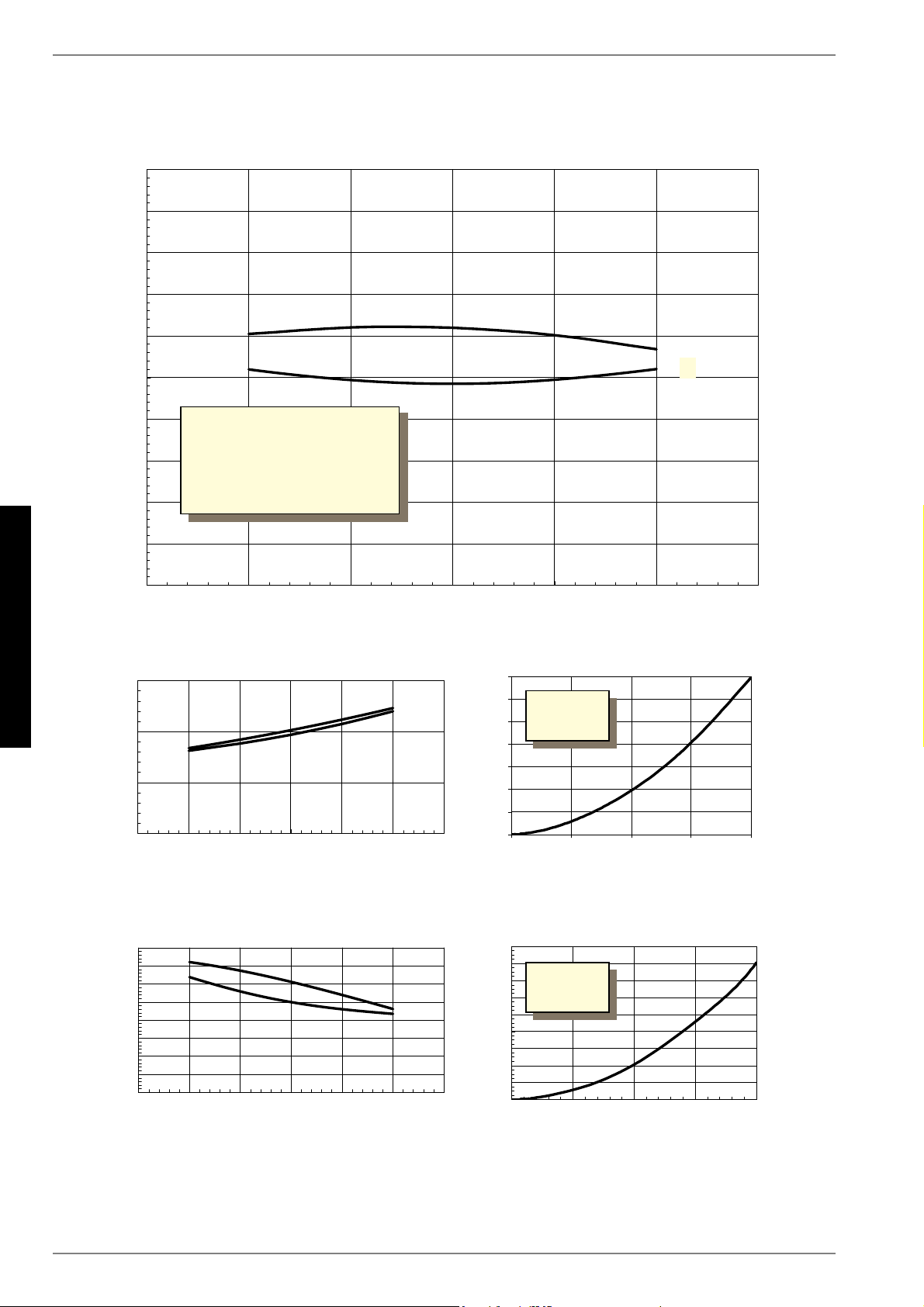
1.Diese Angaben charakterisieren die Größe und die Leistungsfähigkeit der Anlage. Für wirtschaftliche und energetische Betrachtungen sind Bivalenzpunkt und Regelung zu be-
rücksichtigen. Dabei bedeuten z.B. B10/ W55: Wärmequellentemperatur 10°C und Heizwasser-Vorlauftemperatur 55°C.
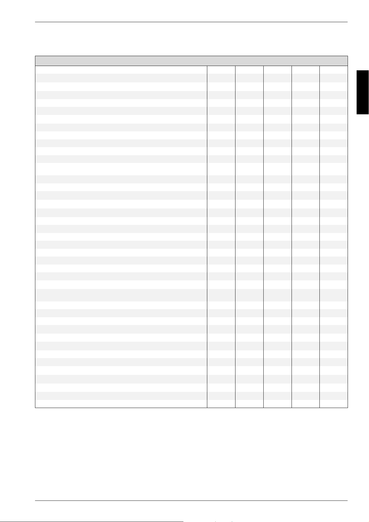
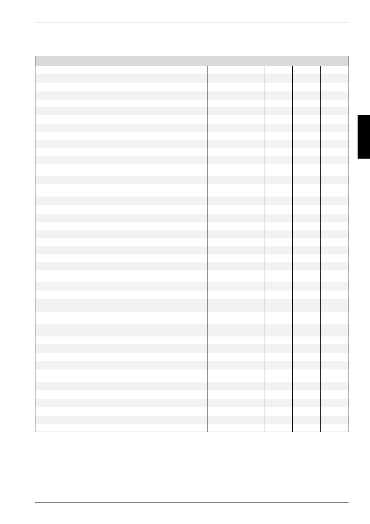
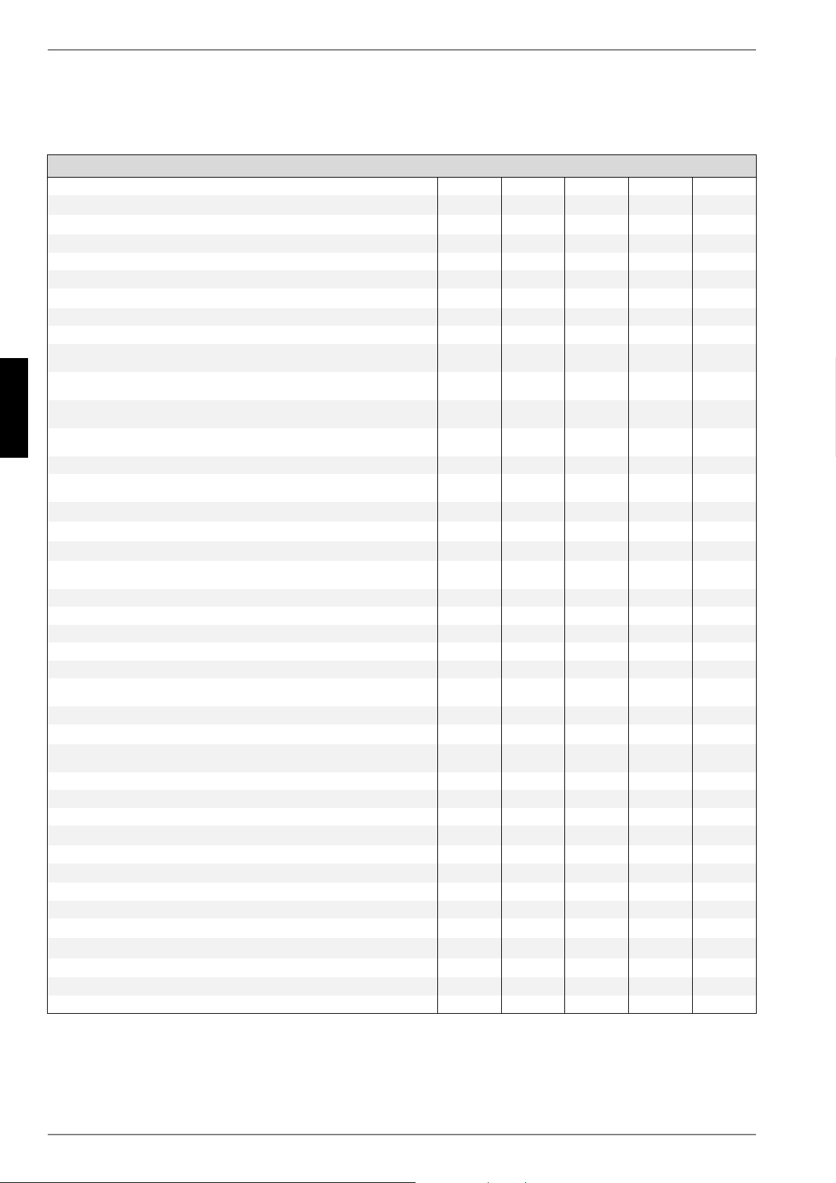
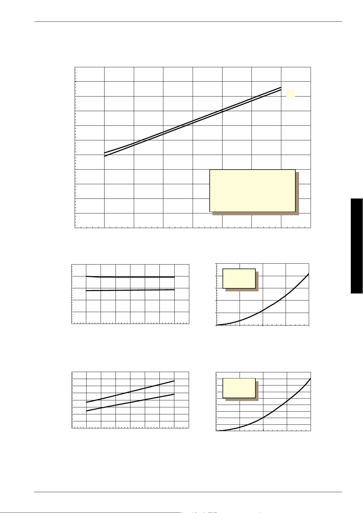
Heating water flow°CUp to 55Up to 55Up to 55Up to 55Up to 55
Cooling, flow°C+8 to +20+8 to +20+8 to +20+8 to +20+8 to +20
Brine (heat source, heating)°C-5 to +25-5 to +25-5 to +25-5 to +25-5 to +25
Brine (heat sink, cooling)°C+5 to +25+5 to +25+5 to +25+5 to +25+5 to +25
AntifreezeMonoethyl-
ene glycol
Monoethyl-
ene glycol
Monoethyl-
ene glycol
Monoethyl-
ene glycol
Monoethyl-
ene glycol
Minimum brine concentration (-13 °C freezing temperature)25%25%25%25%25%
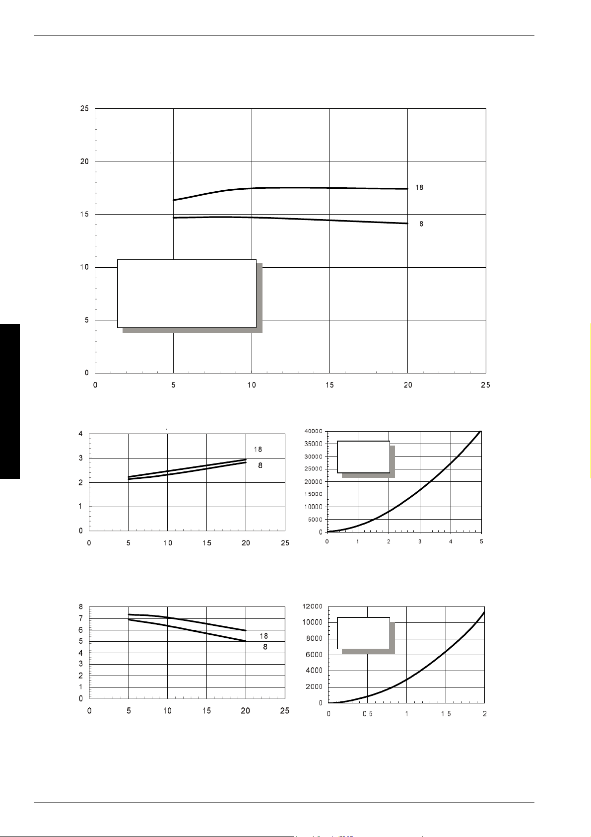
3.2Temperature spread of heating water
(flow/return flow) at B0 / W35K9.99.910.49.99.4
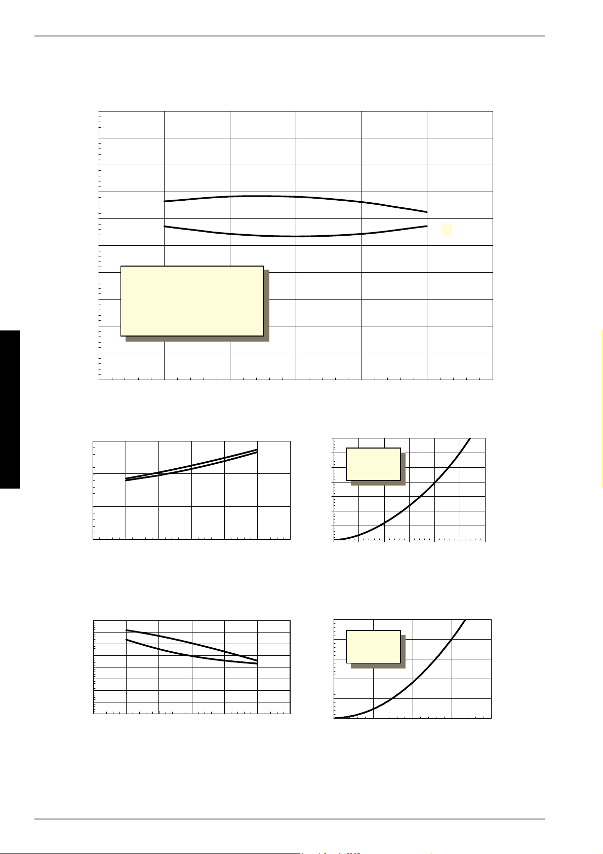
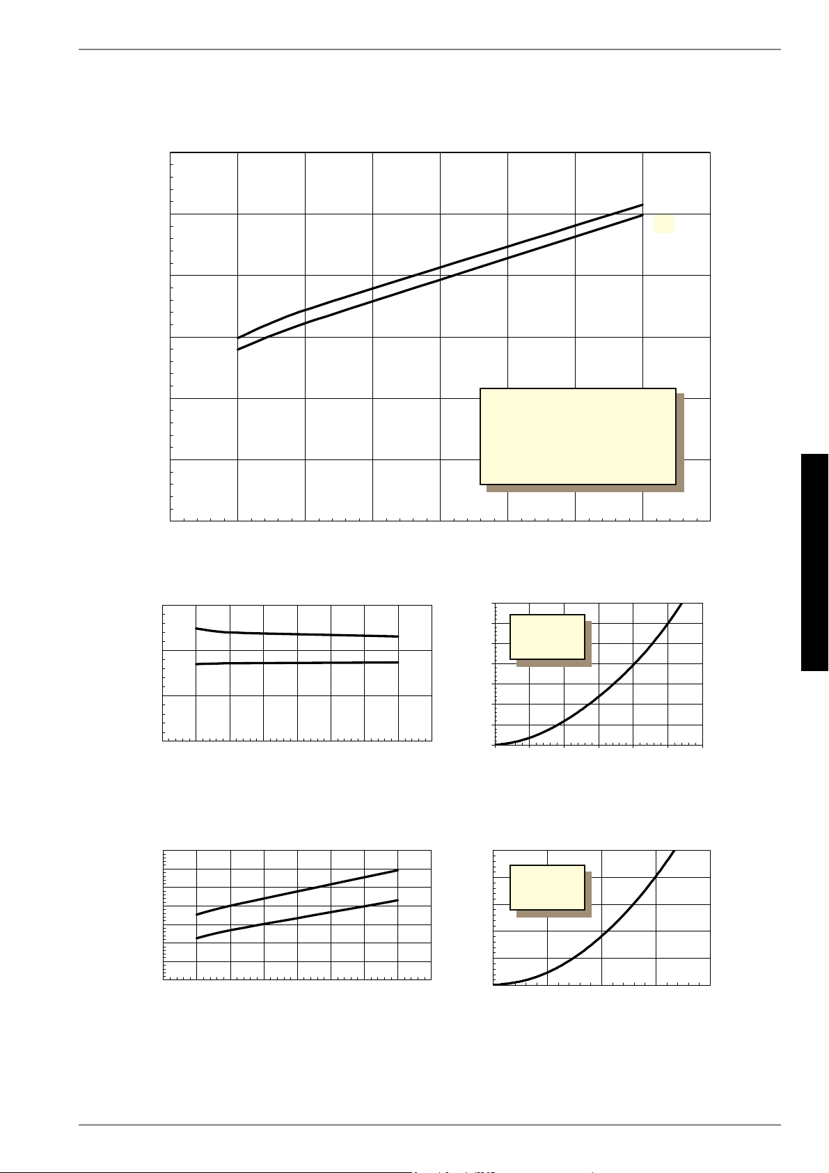
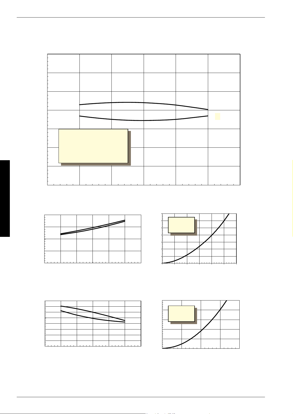
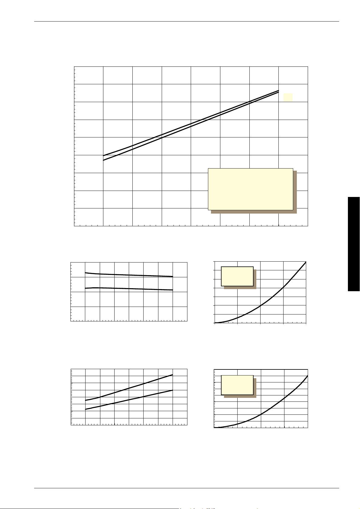
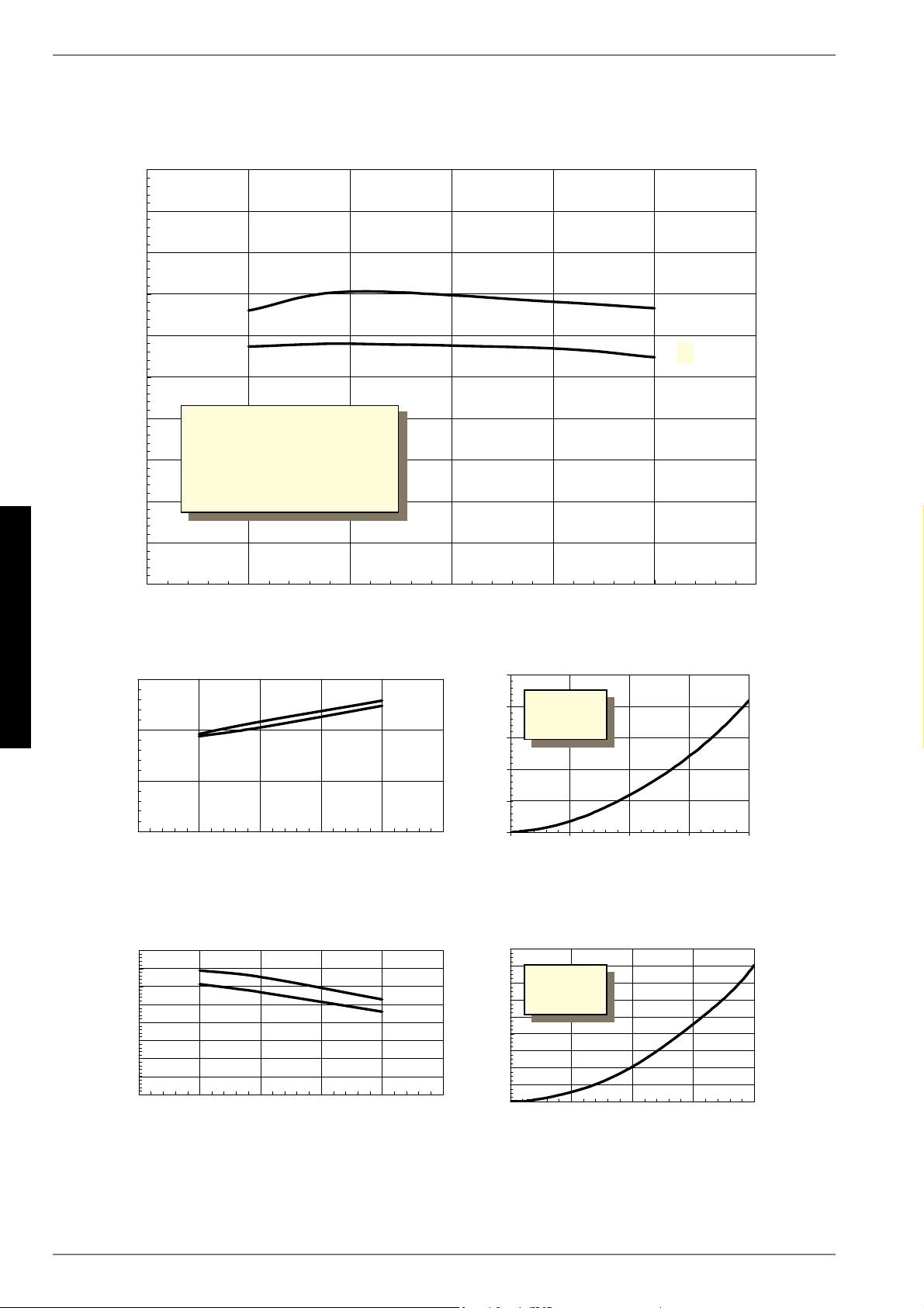
3.3Heat output / COPat B-5 / W55 1kW / ---
1.This data indicates the size and capacity of the system. For an analysis of the economic and energy efficiency of the system, both the bivalence point and the regulation should
also be taken into consideration. The specified values, e.g. B10/ W55, have the following meaning: Heat source temperature 10°C and heating water flow temperature 55°C.
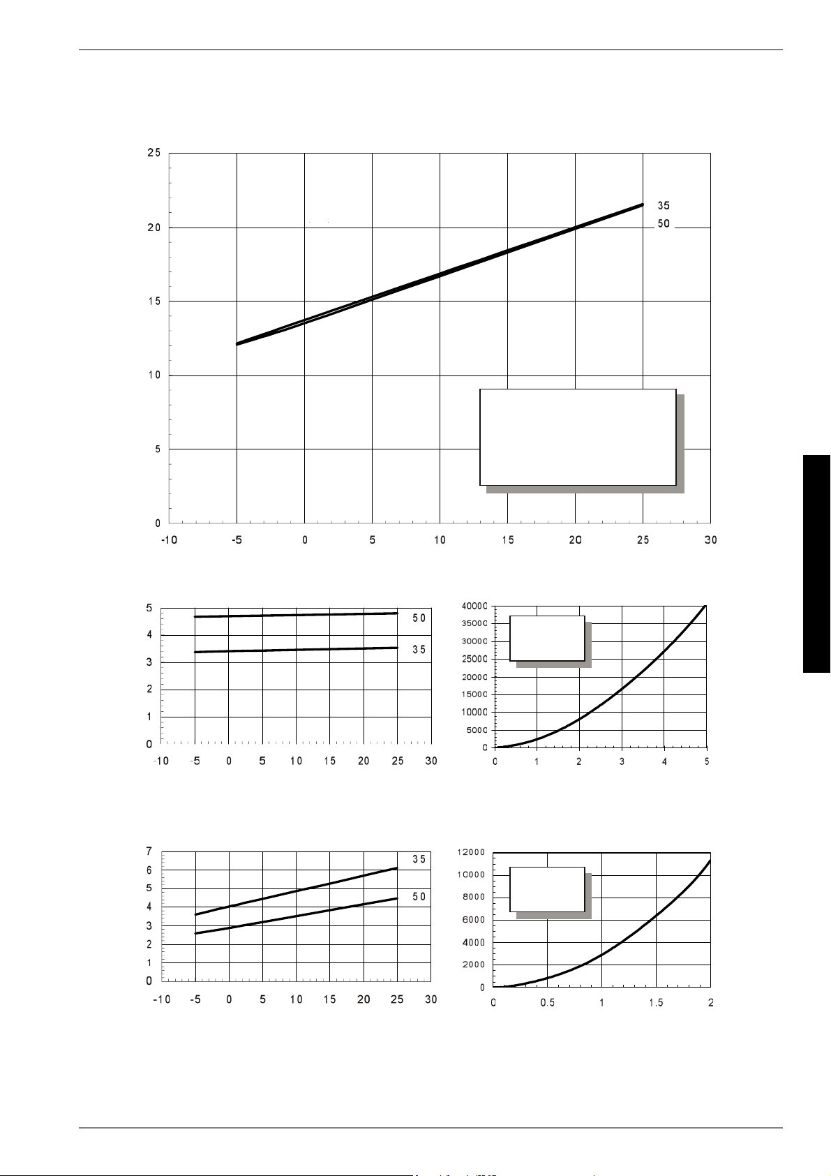
1.Ces indications caractérisent la taille et le rendement de l’installation. Le point de bivalence et la régulation sont à prendre en compte pour des considérations économiques et
énergétiques. Ici, B10/W55 signifie par ex. : température extérieure 10°C et température départ eau de chauffage 55°C.
Gebruikershandleiding.com neemt misbruik van zijn services uitermate serieus. U kunt hieronder aangeven waarom deze vraag ongepast is. Wij controleren de vraag en zonodig wordt deze verwijderd.
Product:
Spelregels forum
Om tot zinvolle vragen te komen hanteren wij de volgende spelregels:
lees eerst de handleiding door;
controleer of uw vraag al eerder door iemand anders is gesteld;
probeer uw vraag zo duidelijk mogelijk te stellen;
heeft u een probleem en al geprobeerd om dit op te lossen, vermeld dit erbij aub;
heeft u een oplossing gekregen van een bezoeker dan horen wij dat graag in dit forum;
wilt u een reactie geven op een vraag of antwoord, gebruik dan niet dit formulier maar klik op de knop 'reageer op deze vraag';
uw vraag wordt direct op de website gezet; vermijd daarom persoonlijke gegevens in te vullen;
Belangrijk! Als er een antwoord wordt gegeven op uw vraag, dan is het voor de gever van het antwoord nuttig om te weten als u er wel (of niet) mee geholpen bent! Wij vragen u dus ook te reageren op een antwoord.
Belangrijk! Antwoorden worden ook per e-mail naar abonnees gestuurd. Laat uw emailadres achter op deze site, zodat u op de hoogte blijft. U krijgt dan ook andere vragen en antwoorden te zien.
Abonneren
Abonneer u voor het ontvangen van emails voor uw Dimplex SI 9USR bij:
nieuwe vragen en antwoorden
nieuwe handleidingen
U ontvangt een email met instructies om u voor één of beide opties in te schrijven.
Ontvang uw handleiding per email
Vul uw emailadres in en ontvang de handleiding van Dimplex SI 9USR in de taal/talen: Duits, Engels, Frans als bijlage per email.
De handleiding is 4.69 mb groot.
U ontvangt de handleiding per email binnen enkele minuten. Als u geen email heeft ontvangen, dan heeft u waarschijnlijk een verkeerd emailadres ingevuld of is uw mailbox te vol. Daarnaast kan het zijn dat uw internetprovider een maximum heeft aan de grootte per email. Omdat hier een handleiding wordt meegestuurd, kan het voorkomen dat de email groter is dan toegestaan bij uw provider.
Stel vragen via chat aan uw handleiding
Stel uw vraag over deze PDF
Uw handleiding is per email verstuurd. Controleer uw email
Als u niet binnen een kwartier uw email met handleiding ontvangen heeft, kan het zijn dat u een verkeerd emailadres heeft ingevuld of dat uw emailprovider een maximum grootte per email heeft ingesteld die kleiner is dan de grootte van de handleiding.
Er is een email naar u verstuurd om uw inschrijving definitief te maken.
Controleer uw email en volg de aanwijzingen op om uw inschrijving definitief te maken
U heeft geen emailadres opgegeven
Als u de handleiding per email wilt ontvangen, vul dan een geldig emailadres in.
Uw vraag is op deze pagina toegevoegd
Wilt u een email ontvangen bij een antwoord en/of nieuwe vragen? Vul dan hier uw emailadres in.