1.1Symbole und Kennzeichnung......................................................................................................................................DE-2
1.3Gesetzliche Vorschriften und Richtlinien.................................................................................................................DE-2
1.4Energiesparende Handhabung der Wärmepumpe..............................................................................................DE-2
2Verwendungszweck der Wärmepumpe................................................................................................DE-2
8.3Vorgehensweise bei Inbetriebnahme.......................................................................................................................DE-8
2.4Aufstellungsort / Schutzart nach EN 60 529Innen / IP 21Innen / IP 21Innen / IP 21
2.5Leistungsstufen111
3Einsatzgrenzen
3.1Heizwasser-Vorlauf1 °C
1.Bei Bedarf kann der Einsatzbereich bis zu einer Soleeintrittstemperatur von -10 C° erweitert werden. In diesem Fall ist die minimale Solekonzentration auf 30% anzupassen.
(Einfriertemperatur -17 C°). Bei Soleeintrittstemperaturen von -10 C° bis -5 C°, Vorlauftemperatur von 55 C° bis 62 C° steigend.
20 bis 62 ±220 bis 62 ±220 bis 62 ±2
3.2Sole (Wärmequelle Heizen)°C
Frostschutzmittel
Minimale Solekonzentration (-13 °C Einfriertemperatur)1
-51 bis +252
Monoethylenglykol
25 %1
2.Der Betrieb ist bis zu einer Soleeintrittstemperatur von +35°C möglich. Bei Soleeintrittstemperaturen von +25°C bis +35°C, Vorlauftempertur von 62°C bis 55°C fallend.
4Leistungsangaben / Durchfluss3
3.Diese Angaben charakterisieren die Größe und die Leistungsfähigkeit der Anlage nach EN 14511. Für wirtschaftliche und energetische Betrachtungen sind Bivalenzpunkt und
Regler zu berücksichtigen. Dabei bedeuten z.B. B0W55: Wärmequellentemperatur 0 °C und Heizwasser-Vorlauftemperatur 55 °C. Diese Angaben werden ausschließlich mit
sauberem Wärmeübertragern erreicht. Hinweise zur Pflege, Inbetriebnahme und Betrieb sind den entsprechenden Abschnitten der Montage- und Gebrauchsanleitung zu ent-
4.Die angegebenen Schallwerte gelten ohne die optional erhältlichen Stellfüße. Bei Verwendung der Stellfüße kann sich der Pegel um bis zu 3db (A) erhöhen
464647
4.4Schall-Druckpegel in 1m Entfernung 55dB(A)
5.Der angegebene Schalldruckpegel entspricht dem Betriebsgeräusch der Wärmepumpe im Heizbetrieb bei 35 °C Vorlauftemperatur.
Der angegebene Schalldruckpegel stellt den Freifeldpegel dar. Je nach Aufstellungsort kann der Messwert um bis zu 16 dB (A) abweichen.
2.4Aufstellungsort / Schutzart nach EN 60 529Innen / IP 21Innen / IP 21
2.5Leistungsstufen11
3Einsatzgrenzen
3.1Heizwasser-Vorlauf1 °C
1.Bei Bedarf kann der Einsatzbereich bis zu einer Soleeintrittstemperatur von -10 C° erweitert werden. In diesem Fall ist die minimale Solekonzentration auf 30% anzupassen.
(Einfriertemperatur -17 C°). Bei Soleeintrittstemperaturen von -10 C° bis -5 C°, Vorlauftemperatur von 55 C° bis 62 C° steigend.
20 bis 62 ±220 bis 62 ±2
3.2Sole (Wärmequelle Heizen)°C
Frostschutzmittel
Minimale Solekonzentration (-13 °C Einfriertemperatur)1
-51 bis +252
Monoethylenglykol
25 %1
2.Der Betrieb ist bis zu einer Soleeintrittstemperatur von +35°C möglich. Bei Soleeintrittstemperaturen von +25°C bis +35°C, Vorlauftempertur von 62°C bis 55°C fallend.
-51 bis +252
Monoethylenglykol
25 %1
4Leistungsangaben / Durchfluss3
3.Diese Angaben charakterisieren die Größe und die Leistungsfähigkeit der Anlage nach EN 14511. Für wirtschaftliche und energetische Betrachtungen sind Bivalenzpunkt und
Regler zu berücksichtigen. Dabei bedeuten z.B. B0W55: Wärmequellentemperatur 0 °C und Heizwasser-Vorlauftemperatur 55 °C. Diese Angaben werden ausschließlich mit
sauberem Wärmeübertragern erreicht. Hinweise zur Pflege, Inbetriebnahme und Betrieb sind den entsprechenden Abschnitten der Montage- und Gebrauchsanleitung zu ent-
nehmen.
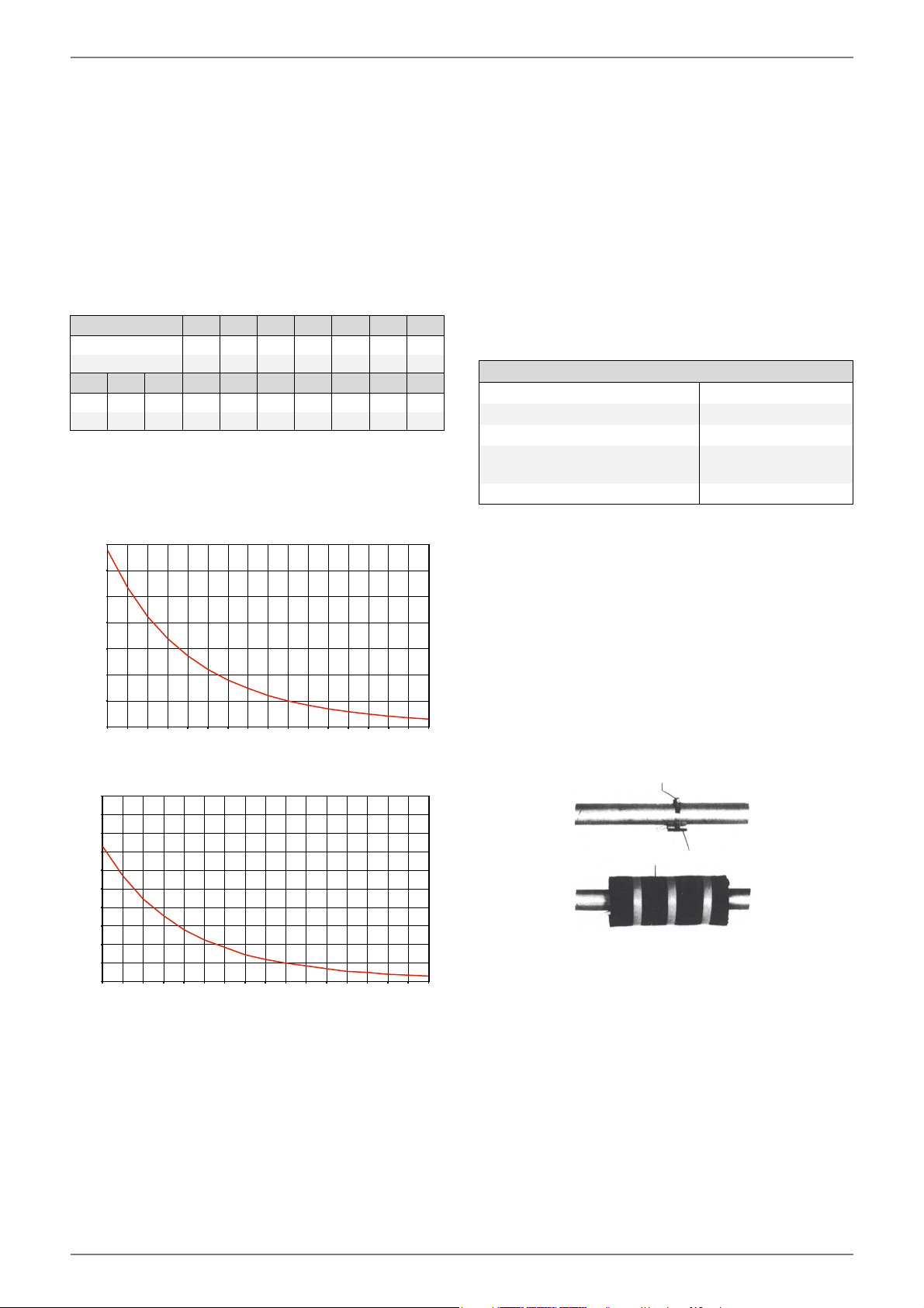
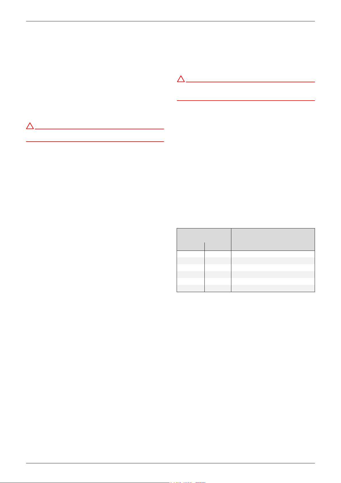
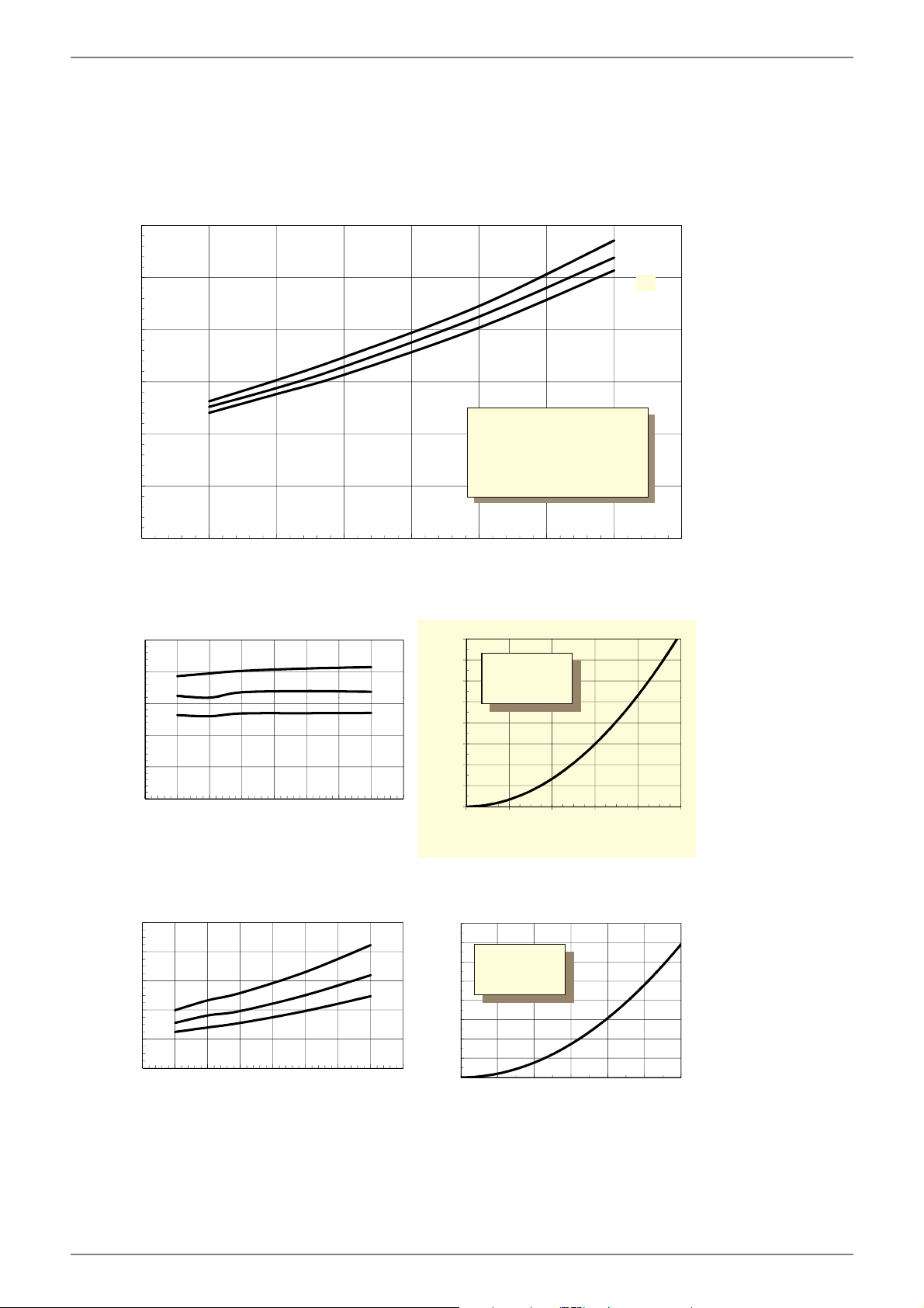
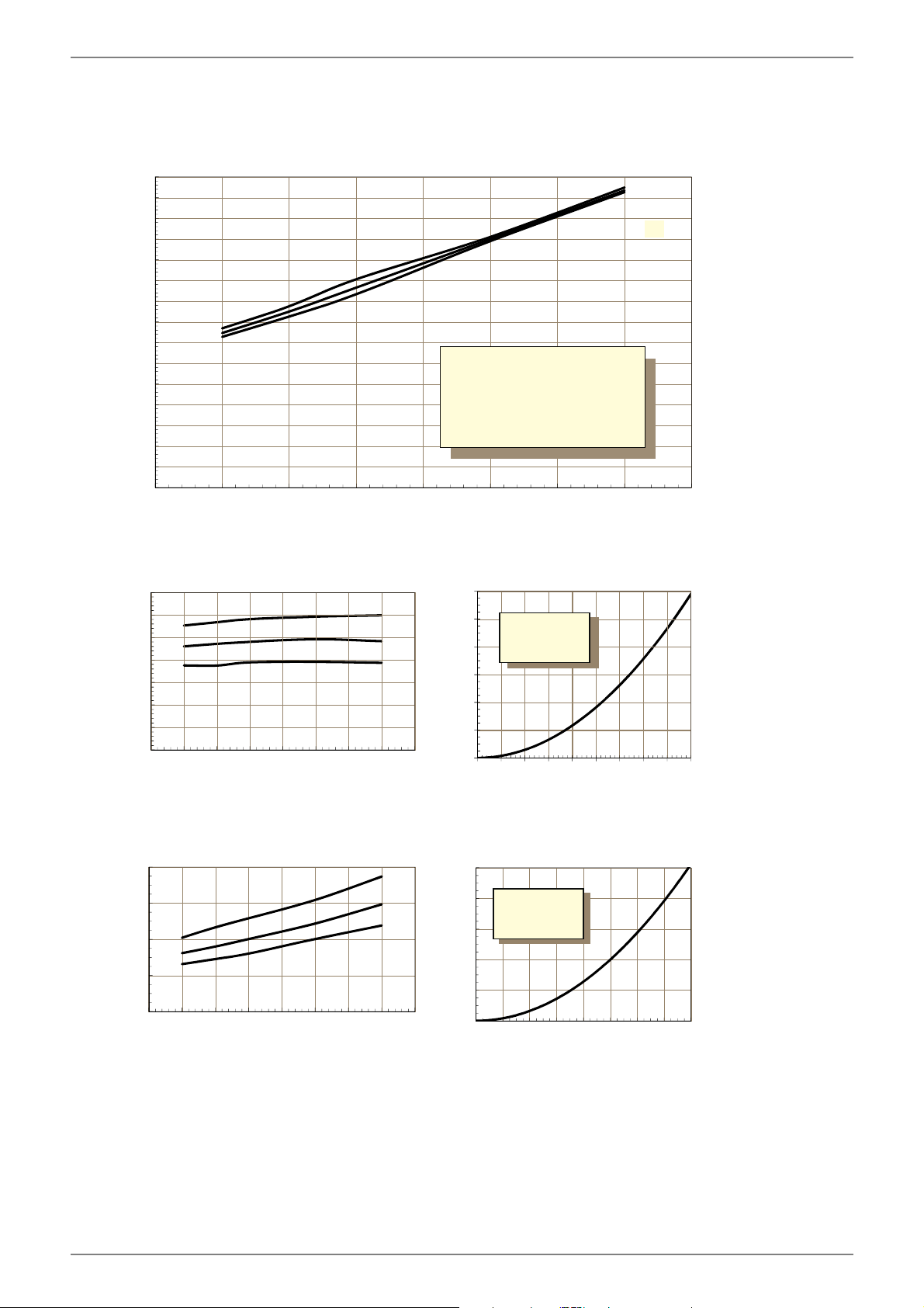
4.1Heizwasserdurchfluss / interne Druckdifferenz
maximal (EN14511) m³/h / Pa
minimalm³/h / Pa
2,4 / 10700
1,2 / 2700
3,0 / 18000
1,5 / 4500
4.2Wärmeleistung / LeistungszahlEN 14511EN 14511
bei B-5 / W45 kW / ---11,5 / 3,314,9 / 3,2
bei B0 / W55 kW / ---12,8 / 3,016,5 / 2,9
bei B0 / W45 kW / ---13,3 / 3,817,0 / 3,6
bei B0 / W35 kW / ---13,9 / 5,017,5 / 4,7
4.3Schall-Leistungspegel nach EN 12102 4 dB(A)
4.Die angegebenen Schallwerte gelten ohne die optional erhältlichen Stellfüße. Bei Verwendung der Stellfüße kann sich der Pegel um bis zu 3db (A) erhöhen.
4750
4.4Schall-Druckpegel in 1m Entfernung 45dB(A)
5.Der angegebene Schalldruckpegel entspricht dem Betriebsgeräusch der Wärmepumpe im Heizbetrieb bei 35 °C Vorlauftemperatur.
Der angegebene Schalldruckpegel stellt den Freifeldpegel dar. Je nach Aufstellungsort kann der Messwert um bis zu 16 dB (A) abweichen.
1.1Symbols and markings...................................................................................................................................................EN-2
1.3Legal Regulations and Directives...............................................................................................................................EN-2
1.4Energy-Efficient Use of the Heat Pump...................................................................................................................EN-2
2Purpose of the Heat Pump........................................................................................................................EN-2
7.2Heating System Connection........................................................................................................................................EN-5
9.2Cleaning the Heating System......................................................................................................................................EN-9
9.3Cleaning the Heat Source System.............................................................................................................................EN-9
technical connection conditions of the energy suppliers
and supply grid operators (e.g. TAB) and
local conditions.
To ensure that the frost protection function of the heat pump
works properly, the heat pump manager must remain con-
nected to the power supply and the flow must be maintained
through the heat pump at all times.
The switching contacts of the output relay are interference-
suppressed. Therefore, depending on the internal resistance of
the measuring instrument, a voltage can also be measured
when the contacts are open. However, this will be much lower
than the line voltage.
Extra-low voltage is connected to controller terminals N1-J1 to
N1-J11; N1-J19; N1-J20; N1-J23 to N1-J26 and terminal strip
X3; X5.1. If, due to a wiring error, the line voltage is mistakenly
connected to these terminals, the heat pump manager will be
destroyed
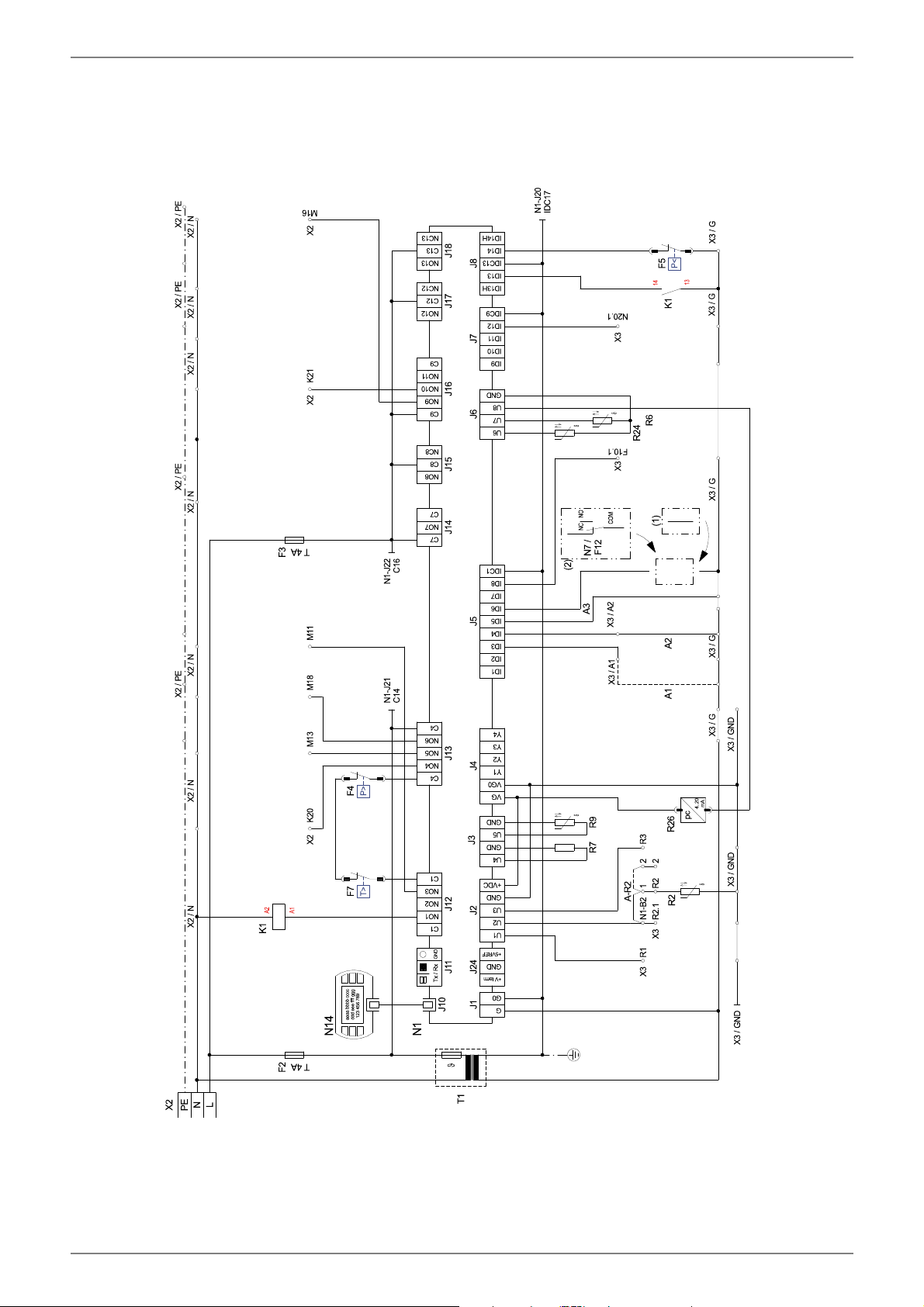
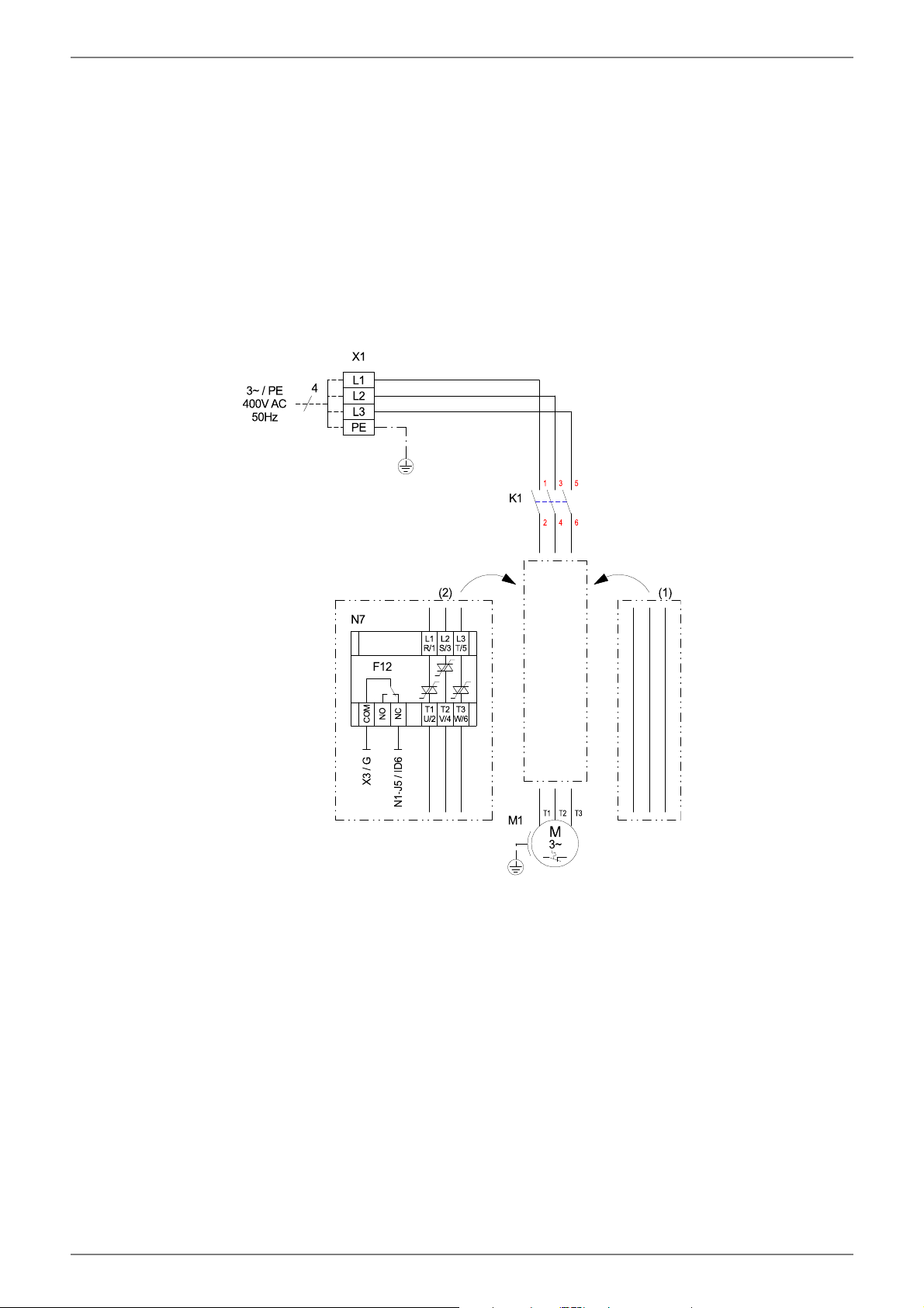
7.5.2Electrical installation
1)The supply electric cable for the output section of the heat
pump (up to 4-core) is fed from the electricity meter of the
heat pump via the utility blocking contactor (if required)
into the heat pump Connection of the mains cable to the
control panel of the heat pump via terminal X1: L1/L2/L3/
PE.
An all-pole disconnecting device with a contact gap of at
least 3 mm (e.g. utility blocking contactor or power contac-
tor) and an all-pole circuit breaker with common tripping
for all external conductors must be installed in the power
supply for the heat pump (tripping current and characteris-
tic in compliance with the device information).
CAUTION!
!
!
Ensure that there is a clockwise rotating field: With incorrect
wiring the starting of the heat pump is prevented. A
corresponding warning is indicated on the display of the heat
pump manager (adjust wiring).
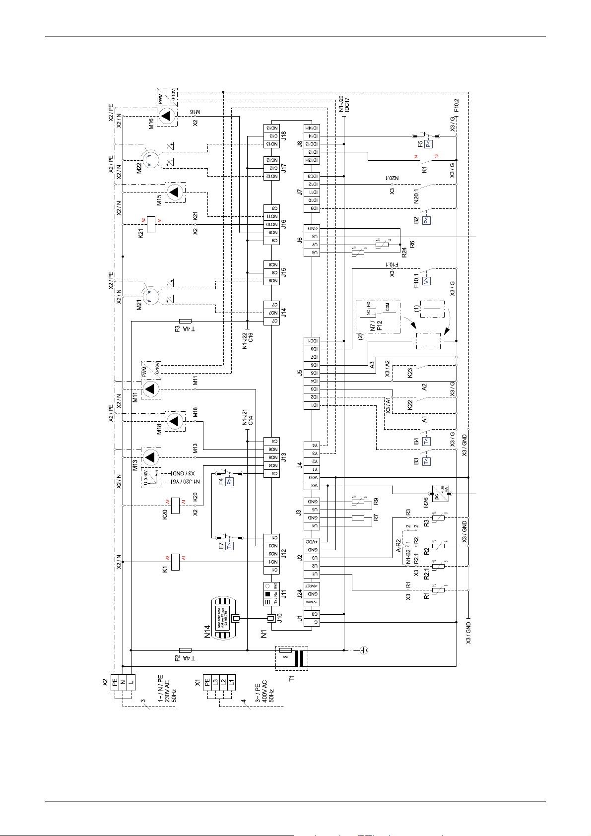
2)The three-core electric supply cable for the heat pump
manager (heating controller N1) is fed into the heat pump .
Connection of the control line to the control panel of the
heat pump via terminal X2: L/N/PE.
Details on the power consumption of the heat pump are
listed on both the product information sheet and the type
plate.
The (L/N/PE~230V, 50Hz) supply cable for the heat pump
manager must have a constant voltage. For this reason, it
should be tapped upstream from the utility blocking con-
tactor or be connected to the household current, as impor-
tant protection functions could otherwise be lost during a
utility block.
3)The utility blocking contactor (K22) with 3 main contacts
(1/3/5 // 2/4/6) and an auxiliary contact (NO contact 13/
14) should be dimensioned according to the heat pump
output and must be supplied by the customer.
The NO contact of the utility blocking contactor (13/14) is
looped from terminal strip X3/G to connector terminal X3/
A1. CAUTION! Extra-low voltage!
4)The contactor (K20) for the immersion heater (E10) of
mono energy systems (HG2) should be dimensioned ac-
cording to the radiator output and must be supplied by the
customer. It is controlled (230VAC) by the heat pump
manager via terminals X2/N andX2/K20.
5)The contactor (K21) for the flange heater (E9) in the hot
water cylinder should be dimensioned according to the ra-
diator output and must be supplied by the customer. It is
controlled (230VAC) by the heat pump manager via termi-
nals X2/N andX2/K21.
6)The contactors mentioned above in points 3, 4 and 5 are
installed in the electrical distribution system. The mains
cable for the installed pipe heater must be laid and secured
in accordance with the valid standards and regulations.
7)All installed electric cables must have permanent wiring.
8)The heat circulating pump (M13) is connected to terminals
X2/N and X2/M13.
9)The DHW loading pump (M18) is connected to terminals
X2/N and X2/M18.
10)The brine or well pump (M11) is connected to terminalsX2/
N and X2/M11 and PE.
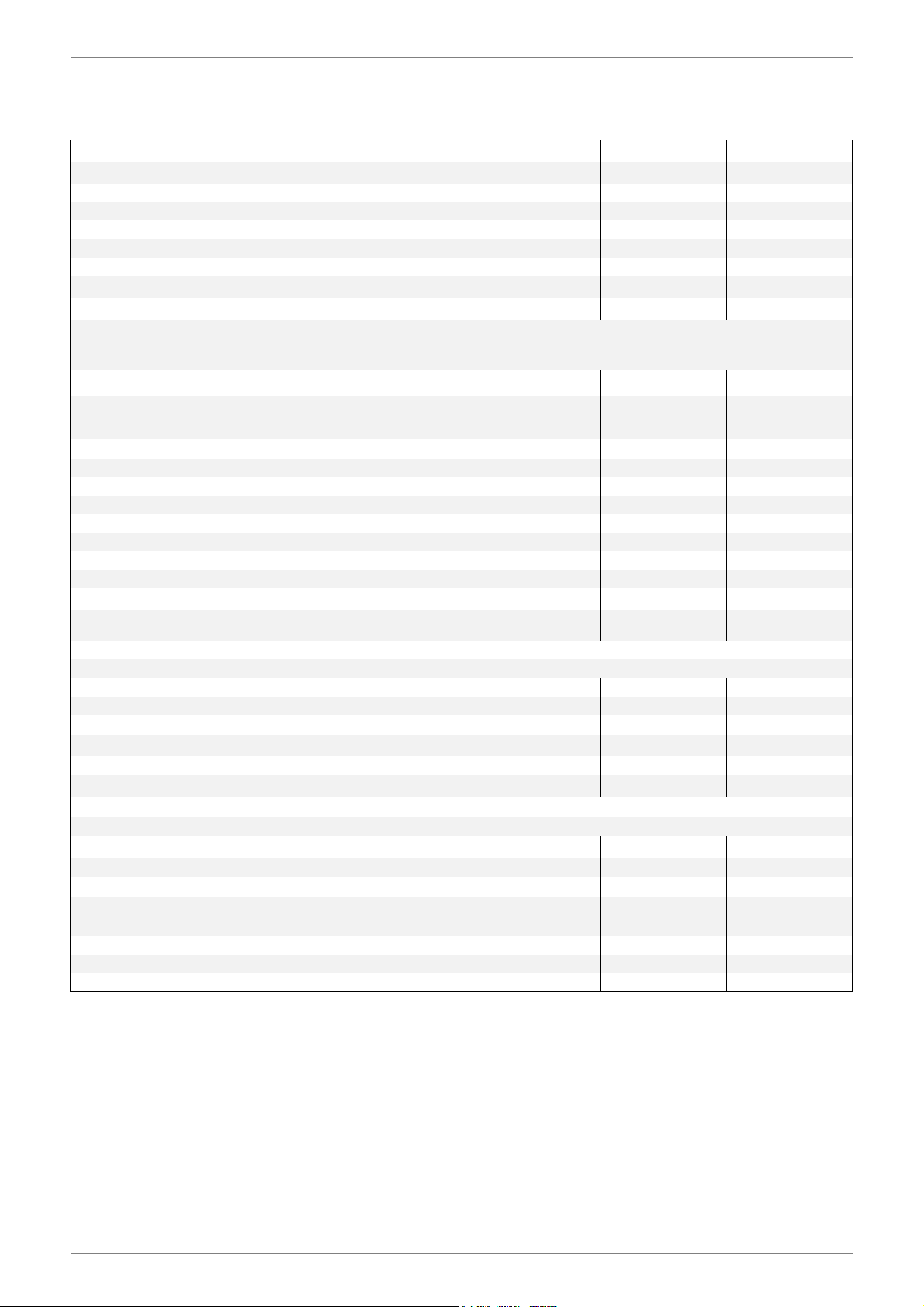
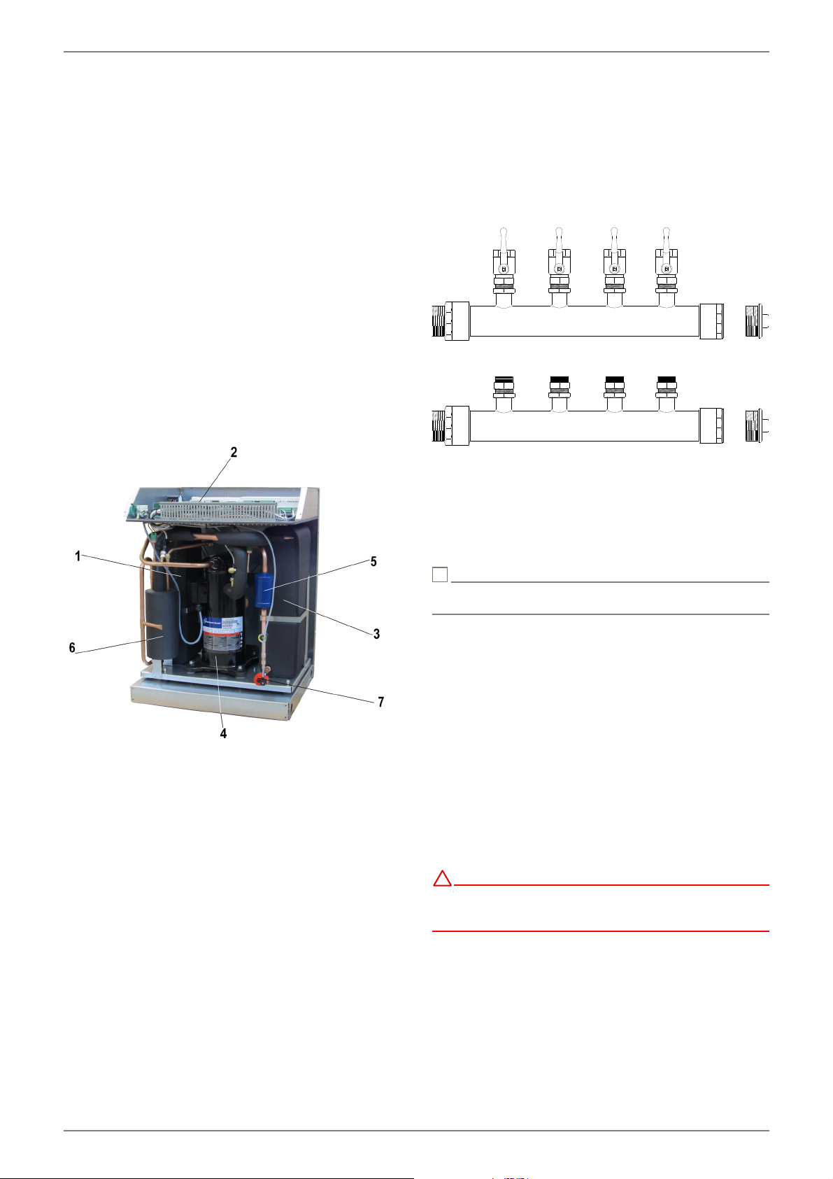
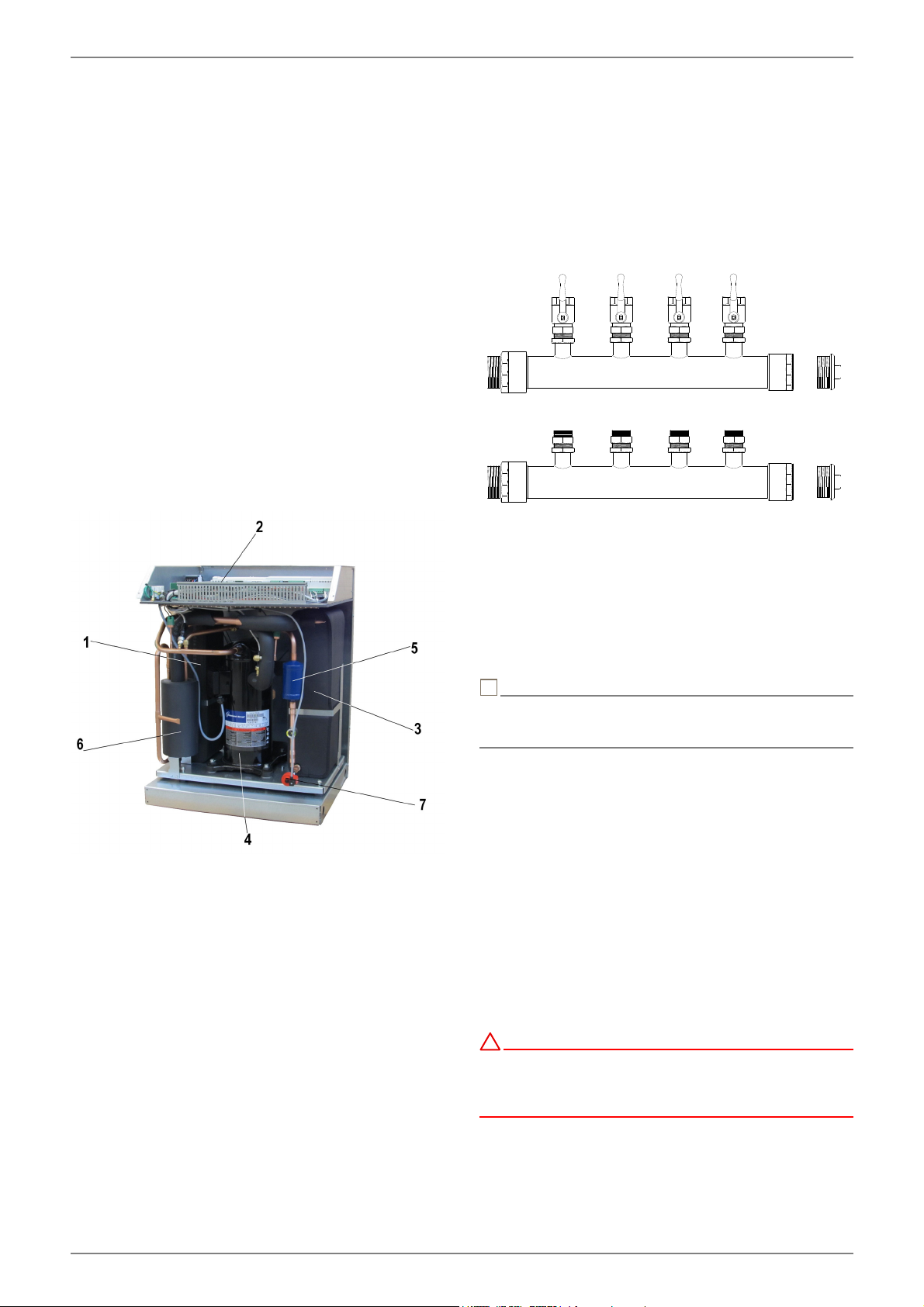
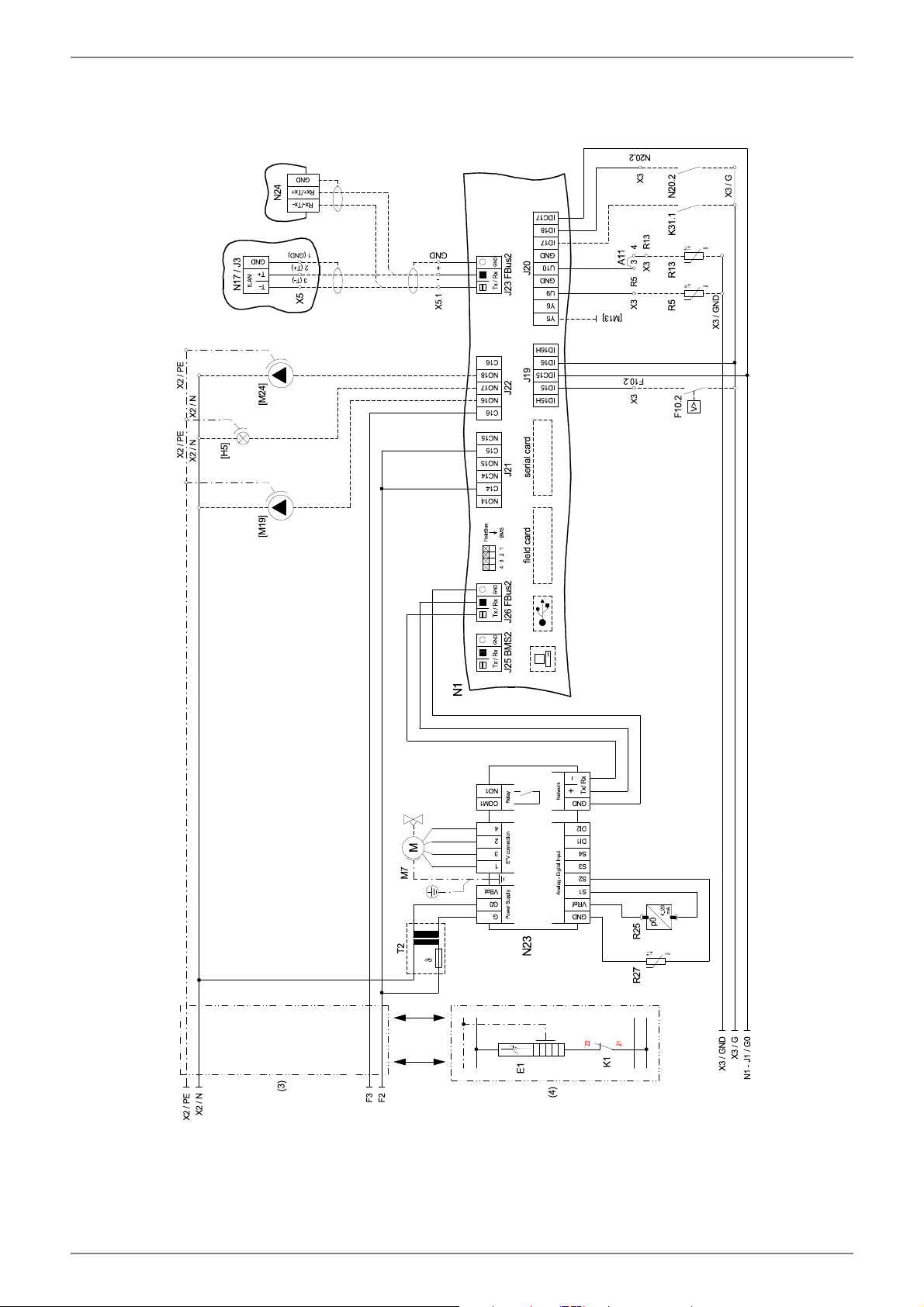
11)The return flow sensor is integrated into the heat pumps
and is connected to the heat pump manager via the control
line. The return flow sensor must be installed in the immer-
sion sleeve in the manifold only when a dual differential
pressureless manifold is used. The single-core wires are
then connected to terminals X3/GND and X3/ R2.1. Bridge
A-R2 (situated between X3/B2 and X3/1 when delivered)
must then be moved to terminals X3/1 and X3/2.
12)The external sensor (R1) is connected to terminals X3/GND
and X3/R1.
13)The domestic hot water sensor (R3) is included with the
domestic hot water cylinder and is connected to terminals
X3/GND and X3/R3.
EN-8452235.66.22a · FD0106www.glendimplex.de
EnglishSI6TU-SI 18TU
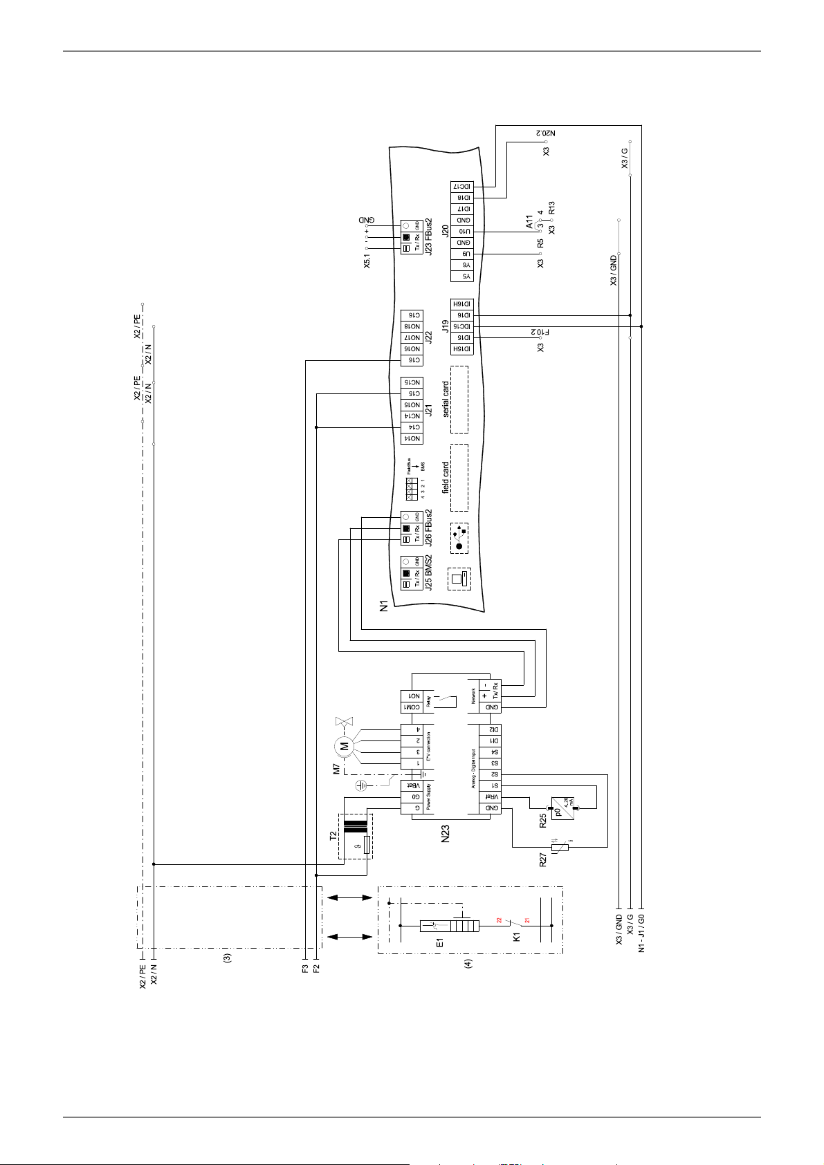
7.5.3Connecting an electronically
regulated circulating pump
Electronically regulated circulating pumps have high starting
currents, which may shorten the service life of the heat pump
manager. For this reason, a coupling relay is installed or must be
installed between the output of the heat pump manager and
the electronically regulated circulating pump. This is not neces-
sary if the permissible operating current of 2 A and a maximum
starting current of 12 A are not exceeded in the electronically
regulated circulating pump or if express approval has been is-
sued by the pump manufacturer.
CAUTION!
!
!
It is not permitted to connect more than one electronically
regulated circulating pump via a relay output.
8Commissioning
8.1General Information
To ensure that start-up is performed correctly, it should only be
carried out by an after-sales service technician authorised by
the manufacturer. These measures can also include an addi-
tional warranty under certain conditions (see Warranty).
8.2Preparation
The following items need to be checked prior to start-up:
The heat pump must be fully connected, as described in
Chapter 7.
The heat source system and the heating circuit must have
been filled and checked.
The dirt trap must be inserted in the brine inlet of the heat
pump.
All valves that could impair proper flow in the brine and
heating circuits must be open.
The heat pump manager must be adapted to the heating
system in accordance with the controller’s operating in-
structions.
8.3Start-up Procedure
The heat pump is started up via the heat pump manager.
CAUTION!
!!
The heat pump must be started up in accordance with the
installation and operating instructions of the heat pump
manager.
If an overflow valve is fitted to assure the minimum heating
water flow rate, the valve must be set in accordance with the re-
quirements of the respective heating system. Incorrect adjust-
ment can lead to faulty operation and increased energy con-
sumption. We recommend carrying out the following
procedure to correctly adjust the overflow valve:
Close all of the heating circuits that may also be closed during
operation (depending on the type of heat pump usage) so that
the most unfavourable operating state - with respect to the
water flow rate - is achieved. This normally means the heating
circuits of the rooms on the south and west sides of the build-
ing. At least one heating circuit must remain open (e.g. bath-
room).
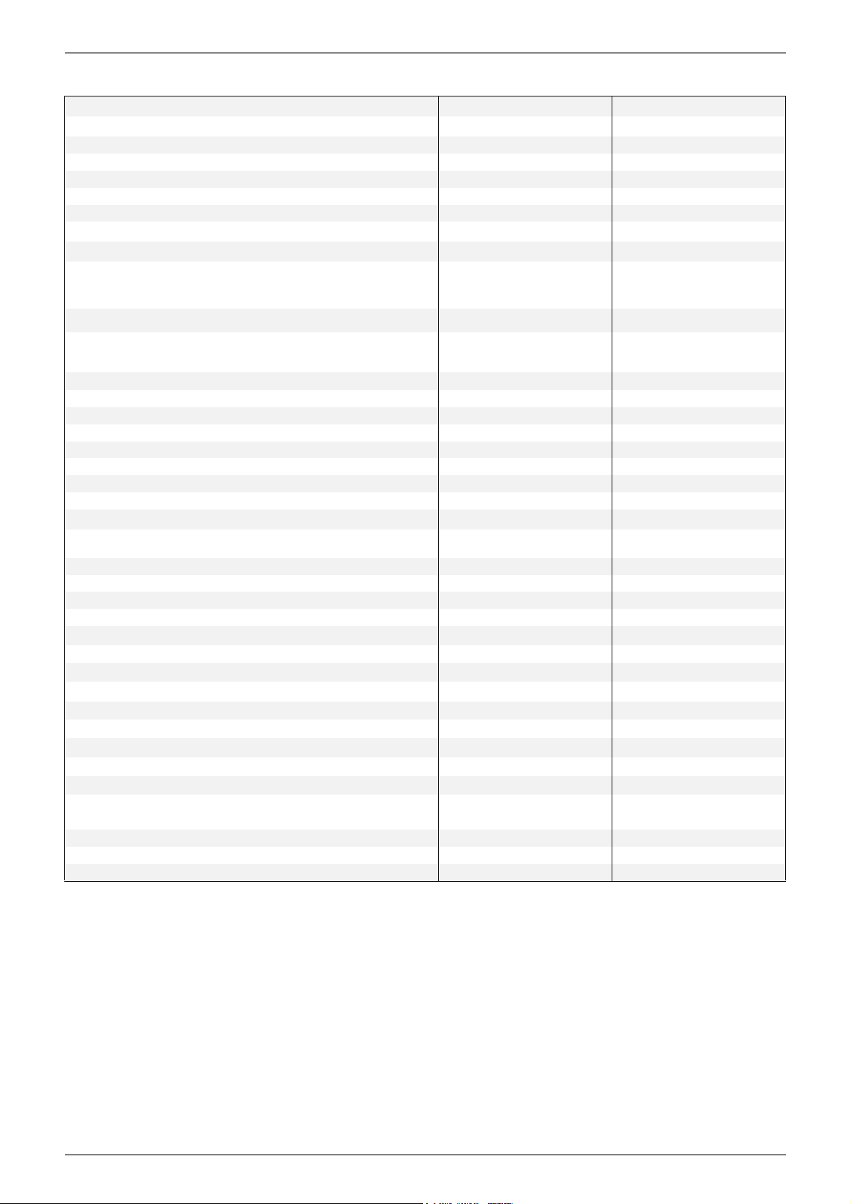
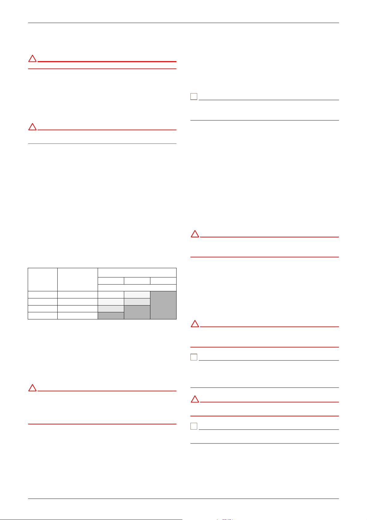
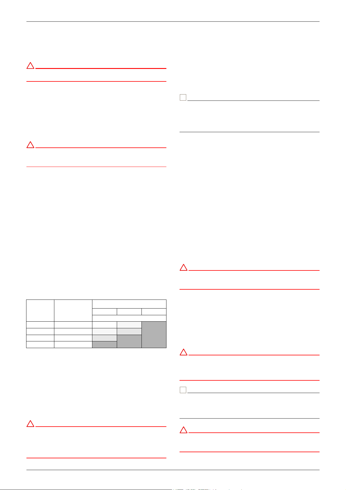
The overflow valve should be opened far enough to produce
the maximum temperature spread between the heating flow
and return flow listed in the table below for the current heat
source temperature. The temperature spread should be meas-
ured as close as possible to the heat pump. The heating ele-
ment of mono energy systems should be disconnected during
start-up.
Heat source
temperatureMax. temperature spread
between heating flow and return
flow
FromTo
-5 °C0 °C10 K
1 °C5 °C11 K
6 °C9 °C12 K
10 °C14 °C13 K
15 °C20 °C14 K
21 °C25 °C15 K
www.glendimplex.de452235.66.22a · FD0106EN-9
SI6TU-SI 18TU English
9Maintenance and Cleaning
9.1Maintenance
To prevent faults due to sediment in the heat exchangers, care
must be taken to ensure that no impurities can enter either the
heat source system or the heating system. In the event that op-
erating malfunctions due to contamination occur nevertheless,
the system should be cleaned as described below.
9.2Cleaning the Heating System
The ingress of oxygen into the heating water circuit may result
in the formation of oxidation products (rust), particularly if steel
components are used. This oxygen enters the heating system
via the valves, the circulating pumps and/or plastic pipes. It is
therefore essential - in particular with respect to the piping of
underfloor heating systems - that only diffusion-proof materials
are used.
NOTE
º
ºººº
We recommend the installation of a suitable corrosion
protection system to prevent the formation of deposits (e.g.
rust) in the condenser of the heat pump.
Residue from lubricants and sealants may also contaminate the
heating water.
In the case of severe contamination leading to a reduction in
the performance of the liquifier in the heat pump, the system
must be cleaned by a heating technician.
Based on current information, we recommend using a 5%
phosphoric acid solution for cleaning purposes. However, if
cleaning needs to be performed more frequently, a 5% formic
acid solution should be used.
In either case, the cleaning fluid should be at room tempera-
ture. We recommend flushing the heat exchanger in the direc-
tion opposite to the normal flow direction.
To prevent acidic cleaning agents from entering the heating
system circuit, we recommend connecting the flushing device
directly to the flow and return flow of the liquifier. It is important
that the system be thoroughly flushed using appropriate neu-
tralising agents to prevent any damage from being caused by
cleaning agent residue remaining in the system.
Acids must be used with great care and all relevant regulations
of the employers’ liability insurance associations must be ad-
hered to.
The manufacturer's instructions regarding cleaning agent must
be complied with at all times.
9.3Cleaning the Heat Source
System
CAUTION!
!
!
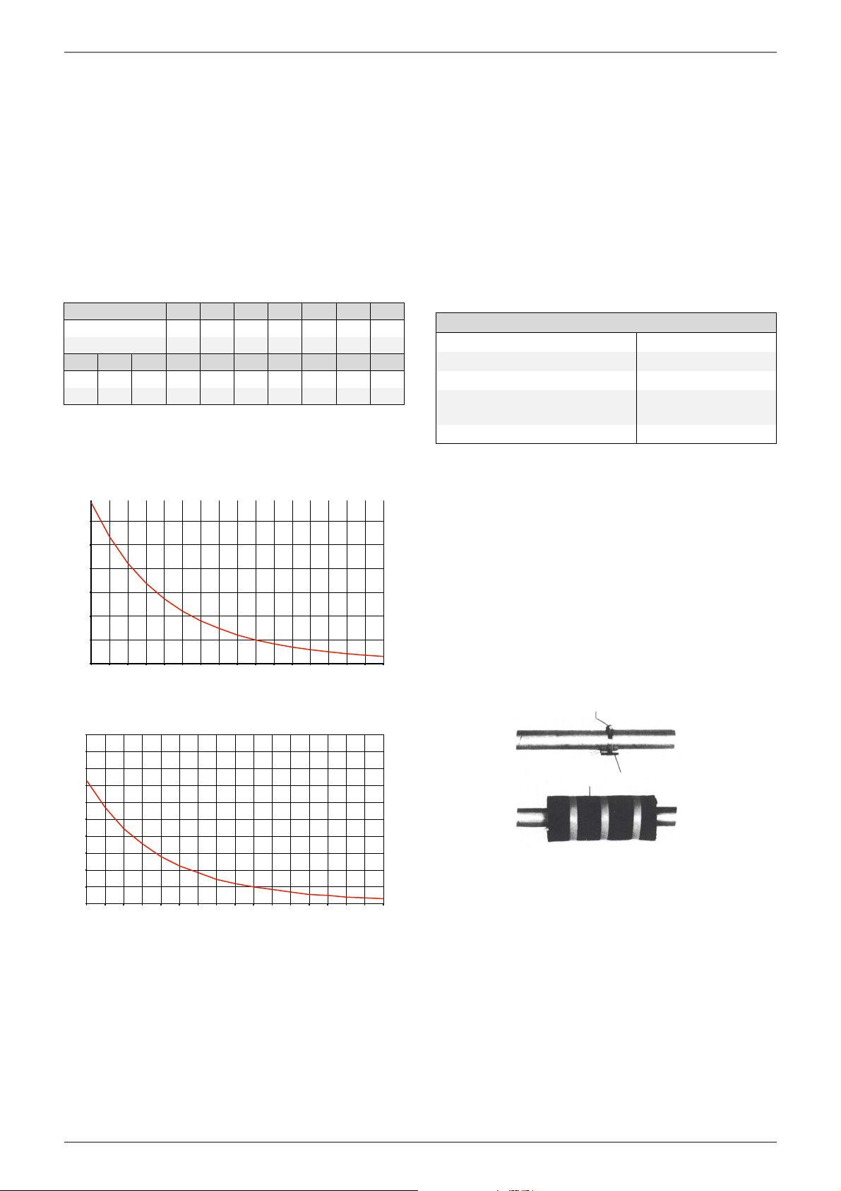
The supplied dirt trap must be inserted in the heat source inlet
of the heat pump to protect the evaporator against the ingress
of impurities.
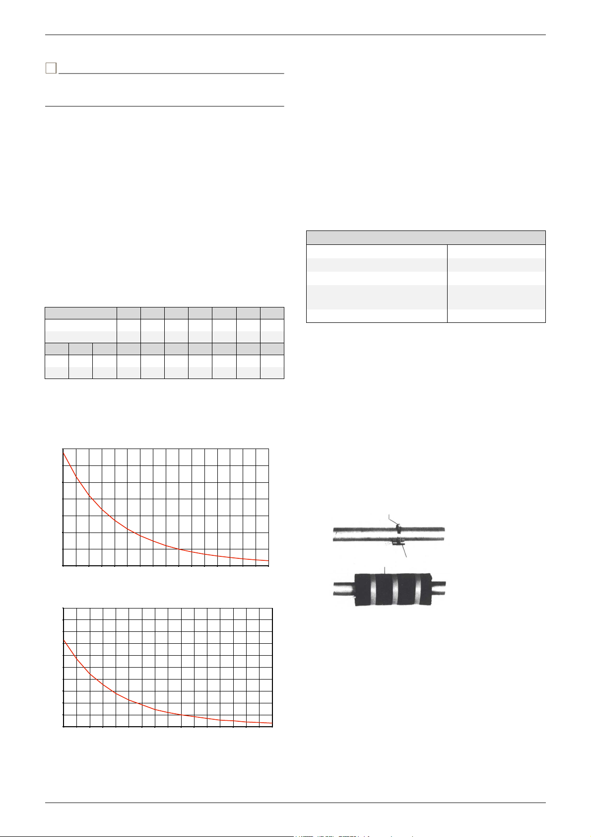
The filter sieve of the dirt trap should be cleaned one day after-
start-up. Further checks must be set according to the level of
dirt.If no more signs of contamination are evident, the filter can
be removed to reduce pressure drops.
10Faults / Trouble-Shooting
This heat pump is a quality product and is designed for trouble-
free operation. In the event that a fault should occur, it will be
indicated on the heat pump manager display. Simply consult
the Faults and Trouble-Shooting page in the operating instruc-
tions of the heat pump manager.
If you cannot correct the fault yourself, please contact your
after-sales service technician.
CAUTION!
!
!
Before opening the device, ensure that all circuits are
disconnected from the power supply!
After disconnecting the power supply, always wait for at least
5minutes to allow stored electric charges to dissipate.
CAUTION!
!
!
Any work on the heat pump may only be performed by
authorised and qualified after-sales service technicians.
11Decommissioning/
Disposal
Before removing the heat pump, disconnect it from the power
source and close all valves. The deinstallation of the heat pump
must be performed by technical personnel. Observe all environ-
mentally-relevant requirements regarding the recovery, recy-
cling and disposal of materials and components in accordance
with all applicable standards. Particular attention should be
paid to the proper disposal of refrigerants and refrigeration oils.
EN-10452235.66.22a · FD0106www.glendimplex.de
EnglishSI6TU-SI 18TU
12Device Information
1Type and order codeSI6TUSI8TUSI11TU
2Design
2.1Model Universal Universal Universal
2.2controllerInternInternIntern
2.3Thermal energy meteringIntegreatedIntegreatedIntegreated
2.4Installation location / degree of protection according to EN 60 529Indoors / IP 21Indoors / IP 21Indoors / IP 21
2.5Performance levels111
3Operating limits
3.1Heating water flow 1°C
1.If necessary, the operating range can be extended to a brine inlet temperature of -10 °C. In this case, the minimum brine concentration must be adjusted to 30%. (Freezing
temperature -17 C°). At brine inlet temperatures of -10 °C to -5 °C, flow temperature rising from 55 °C to 62 °C.
20 to 62 ±20 to 62 ±220 to 62 ±2
3.2Brine (heat source) °C
Antifreeze
Minimum brine concentration (-13 °C freezing temperature)1
-51 to +252
Monoethyleneglycol
25 %1
2.Operation is possible at brine inlet temperatures of up to + 35 °C. At brine inlet temperatures of +25 °C to +35 °C, flow temperature falling from 62 °C to 55 °C.
4Performance data / flow rate 3
3.These data indicate the size and capacity of the system according to EN 14511. For an analysis of the economic and energy efficiency of the system, the bivalence point and
controller should be taken into consideration. The specified values have the following meaning, e.g. B0/W35: Heat source temperature 0 °C and heating water flow temperature
55 °C. These specifications can only be achieved with clean heat exchangers. Information on maintenance, start-up and operation can be found in the respective sections of
the installation and operating instructions.
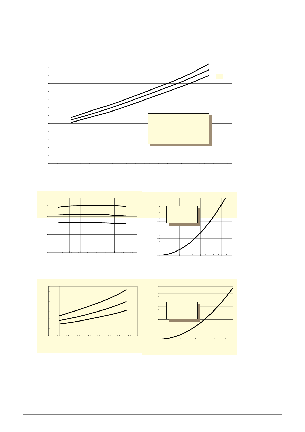
4.1Heating water flow rate at internal pressure differential
max. (EN14511) m³/h / Pa
minimalm³/h / Pa
1.05 / 5300
0.55 / 1500
1.4 / 7700
0.7 / 1900
1.9 / 10500
0.9 / 2400
4.2Heat output / COP EN 14511EN 14511EN 14511
at B-5 / W45 kW / ---5.0 / 3.16.5 / 3.29.1 / 3.2
at B0 / W55 kW / ---5.5 / 2.87.2 / 2.810.0 / 2.9
at B0 / W45 kW / ---5.8 / 3.67.5 / 3,610.4 / 3.7
at B0 / W35 kW / ---6.1 / 4.78.1 / 4.810.9 / 4.9
4.3Sound power level to EN 12102 4dB(A)464647
4.4Sound pressure level at a distance of 1m 45dB(A)
4.The specified sound levels apply if the supporting feet (available as an option) are not used. If the supporting feet are used, the level can increase by up to 3db (A).
5.The specified sound pressure level corresponds to the operating noise of the heat pump in heating operation with a flow temperature of 35°C. The specified sound pressure
level represents the free sound area level. The measured value can deviate by up to 16 dB(A), depending on the installation location.
2.4Installation location / degree of protection according to EN 60 529Indoors / IP 21Indoors / IP 21
2.5Performance levels11
3Operating limits
3.1Heating water flow 1°C
1.If necessary, the operating range can be extended to a brine inlet temperature of -10 °C. In this case, the minimum brine concentration must be adjusted to 30%. (Freezing
temperature -17 C°). At brine inlet temperatures of -10 °C to -5 °C, flow temperature rising from 55 °C to 62 °C.
20 to 62 ±2 20 bis 62 ±2
3.2Brine (heat source) °C
Antifreeze
Minimum brine concentration (-13 °C freezing temperature)1
-51 to +252
Monoethyleneglycol
25 %1
2.Operation is possible at brine inlet temperatures of up to + 35 °C. At brine inlet temperatures of +25 °C to +35 °C, flow temperature falling from 62 °C to 55 °C.
-51 to +252
Monoethylenglykol
25 %1
4Performance data / flow rate 3
3.These data indicate the size and capacity of the system according to EN 14511. For an analysis of the economic and energy efficiency of the system, the bivalence point and
controller should be taken into consideration. The specified values have the following meaning, e.g. B0/W35: Heat source temperature 0 °C and heating water flow temperature
55 °C. These specifications can only be achieved with clean heat exchangers. Information on maintenance, start-up and operation can be found in the respective sections of
the installation and operating instructions.
4.1Heating water flow rate at internal pressure differential
max. (EN14511) m³/h / Pa
minimalm³/h / Pa
2.4 / 10700
1.2 / 2700
3.0 / 18000
1.5 / 4500
4.2Heat output / COP EN 14511EN 14511
at B-5 / W45 kW / ---11.5 / 3.314.9 / 3.2
at B0 / W55 kW / ---12.8 / 3.016.5 / 2.9
at B0 / W45 kW / ---13.3 / 3.817.0 / 3.6
at B0 / W35 kW / ---13.9 / 5.017.5 / 4.7
4.3Sound power level to EN 12102 4dB(A)4750
4.4Sound pressure level at a distance of 1m 45dB(A)
4.The specified sound levels apply if the supporting feet (available as an option) are not used. If the supporting feet are used, the level can increase by up to 3db (A).
5.The specified sound pressure level corresponds to the operating noise of the heat pump in heating operation with a flow temperature of 35°C. The specified sound pressure
level represents the free sound area level. The measured value can deviate by up to 16 dB(A), depending on the installation location.
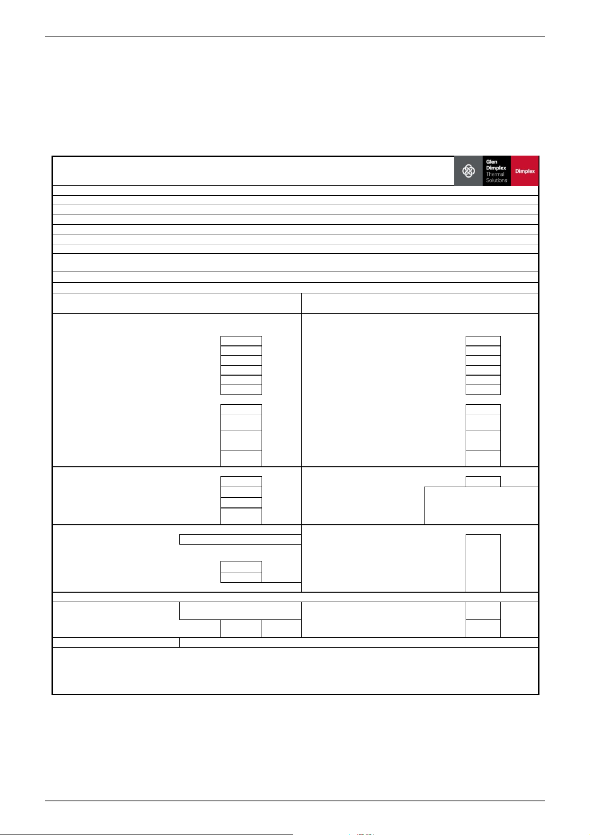
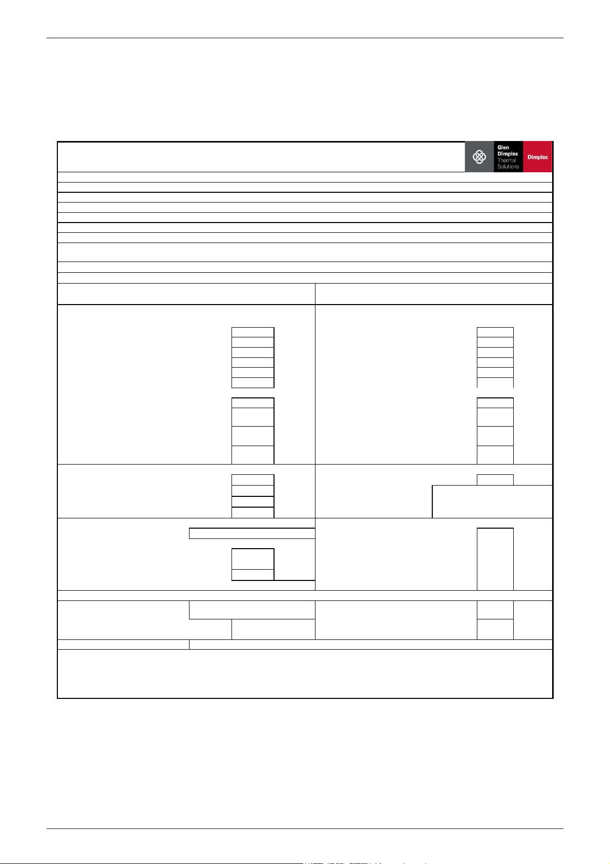
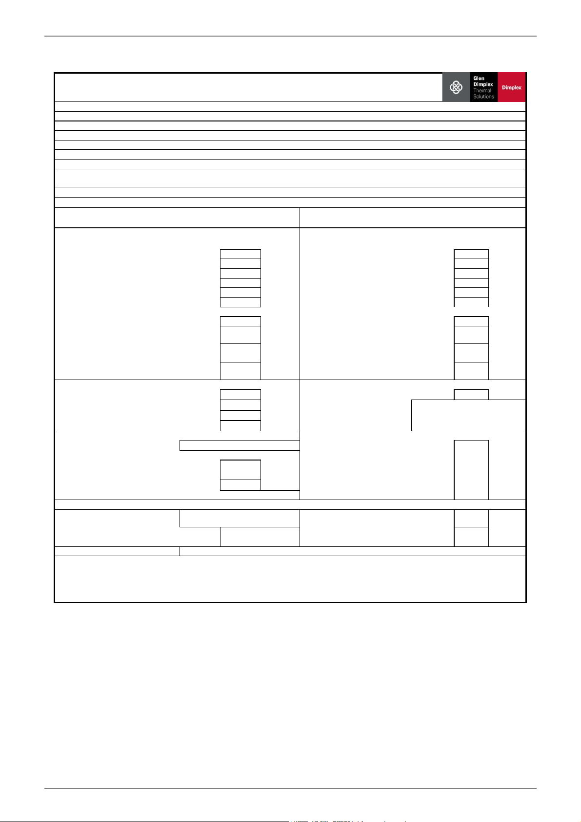
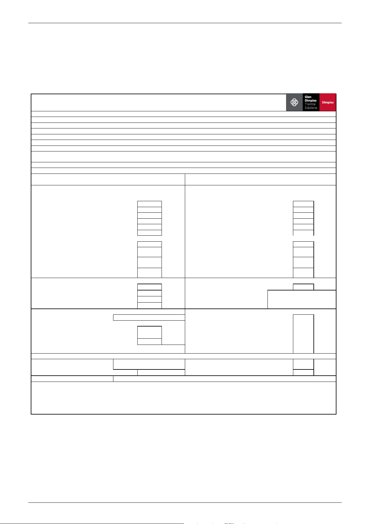
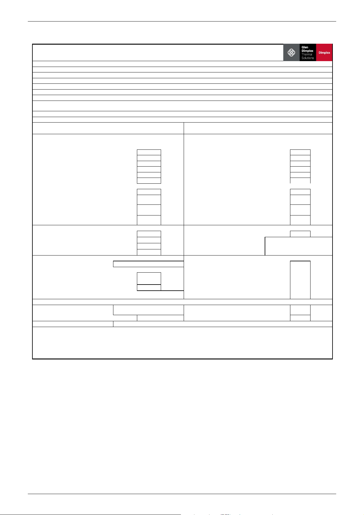
Information requirements for heat pump space heaters and heat pump combination heaters
ItemSymbolValueUnitItemSymbolValue
Unit
Tj = - 7°C
Pdh5,6kWTj = - 7°CCOPd2,95-
Tj = + 2°C
Pdh5,8kWTj = + 2°CCOPd3,58-
Tj = + 7°C
Pdh6,0kWTj = + 7°CCOPd4,09-
Tj = + 12°C
Pdh6,1kWTj = + 12°CCOPd4,72-
Tj = bivalent temperature
Pdh5,5kWTj = bivalent temperatureCOPd2,79-
Tj = operation limit temperature
Pdh5,5kWTj = operation limit temperature COPd2,79-
For air-to-water heat pumps
For air-to-water heat pumps:
Tj = -15°C (if TOL < -20°C)
Pdh5,5kWTj = -15°C (if TOL < -20°C)COPd2,79-
Bivalent temperature
Tbiv-10°C
For air-to-water heat pumps:
Operation limit temperature
TOL-10°C
Cycling interval capacity for heating
Pcych-kWCycling interval efficiencyCOPcyc--
Degradation co-efficient (**)
Cdh0,90-
Heating water operating limit
temperature
WTOL62°C
Power consumption in modes other than active mode
Supplementary heater
Off mode
POFF0,015kWRated heat output (*)Psup0kW
Thermostat-off mode
PTO0,020kWType of energy inputeletrical
Standby mode
PSB0,015kW
Crankcase heater modePCK0,000kW
Other items
Capacity control
fixed--
m³ /h
Sound power level, indoors/ outdoors
LWA46/-dB-1,5
m³ /h
Emissions of nitrogen oxides
NOx-mg/kWh
Declared load profile
-Water heating energy efficiencyηwh-%
Daily electricity consumption
Qelec-kWhDaily fuel consumptionQfuel-
kWh
Contact details
(**) If Cdh is not determined by measurement nthen the default degradation is Cdh = 0,9
(--) not applicable
For air-to-water heat pumps: Rated
air flow rate, outdoors
For water-/brine-to-water heat
pumps: Rated brine or water flow
rate, outdoor heat exchanger
Declared capacity for heating foer part load at indoor temperature 20°C and
outdoor temperature Tj
Declared coefficient of performance or primary energy ratio for part load at
indoor temperature 20 °C and outdoor temperature Tj
For heat pump combination heater:
Glen Dimplex Deutschland GmbH, Am Goldenen Feld 18, 95326 Kulmbach
(*) For heat pump space heaters and heat pump combination heaters, the rated output Prated is equal to the design load for heating Pdesignh, and the rated
heat output of a supplementary capacity for heating sup(Tj).
134
%
Heat pump combination heater
no
Parameters shall be declared for medium-temperature application, except for low-temperature heat pumps. For low- temperature heat pumps, parameters
shall be declared for low-temperature application.
Rated heat output (*)
Prated
6kW
Seasonal space heating energy
efficiency
ηs
Parameters shall be declared for average climate conditions:
Brine-to-water heat pump
yes
Low-temperature heat pump
no
Equipped with a supplementary heater
no
Model
SI 6TU
Air-to-water heat pump
no
Water-to-water heat pump
no
www.glendimplex.de452235.66.22a · FD0106EN-13
SI6TU-SI 18TU English
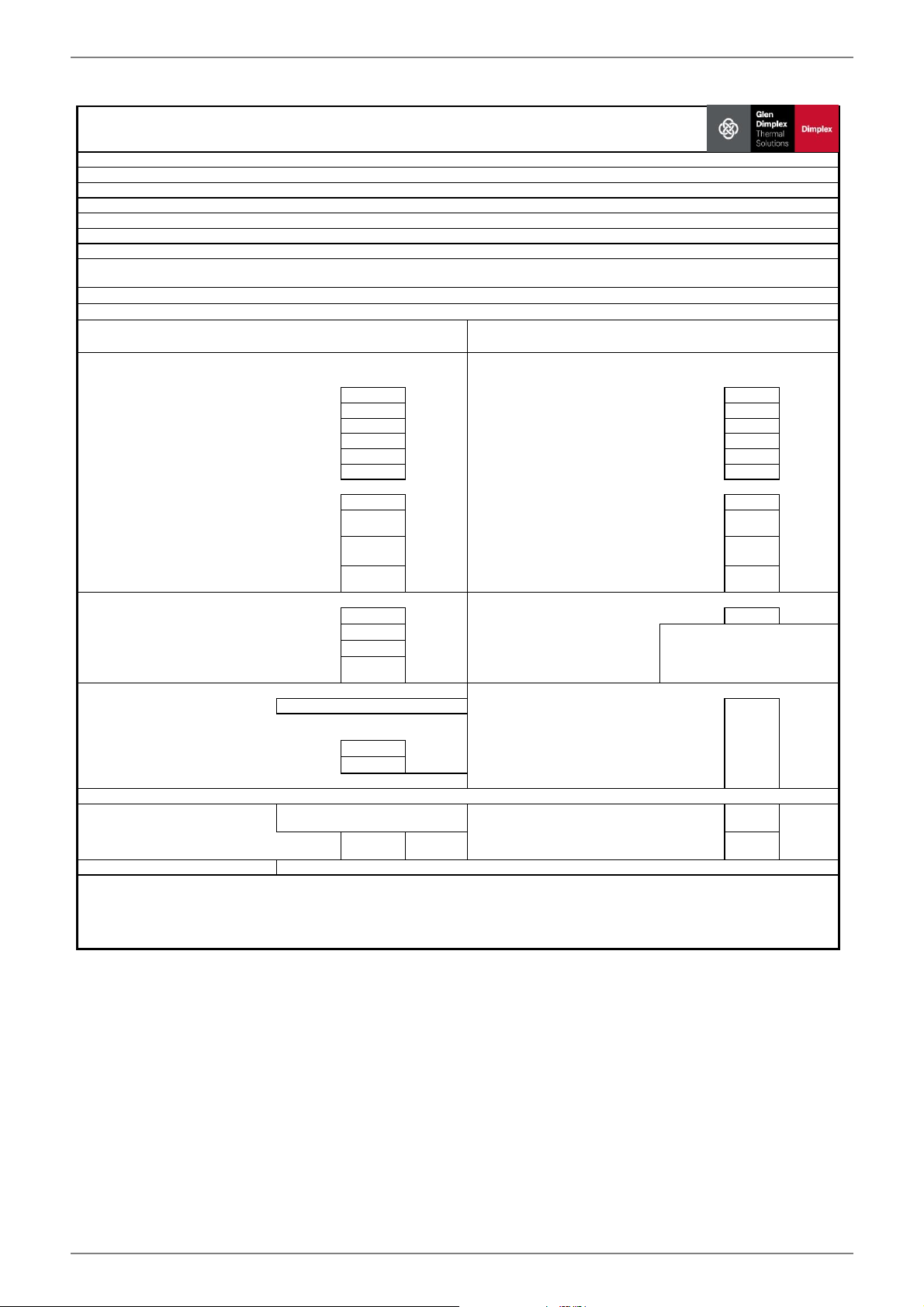
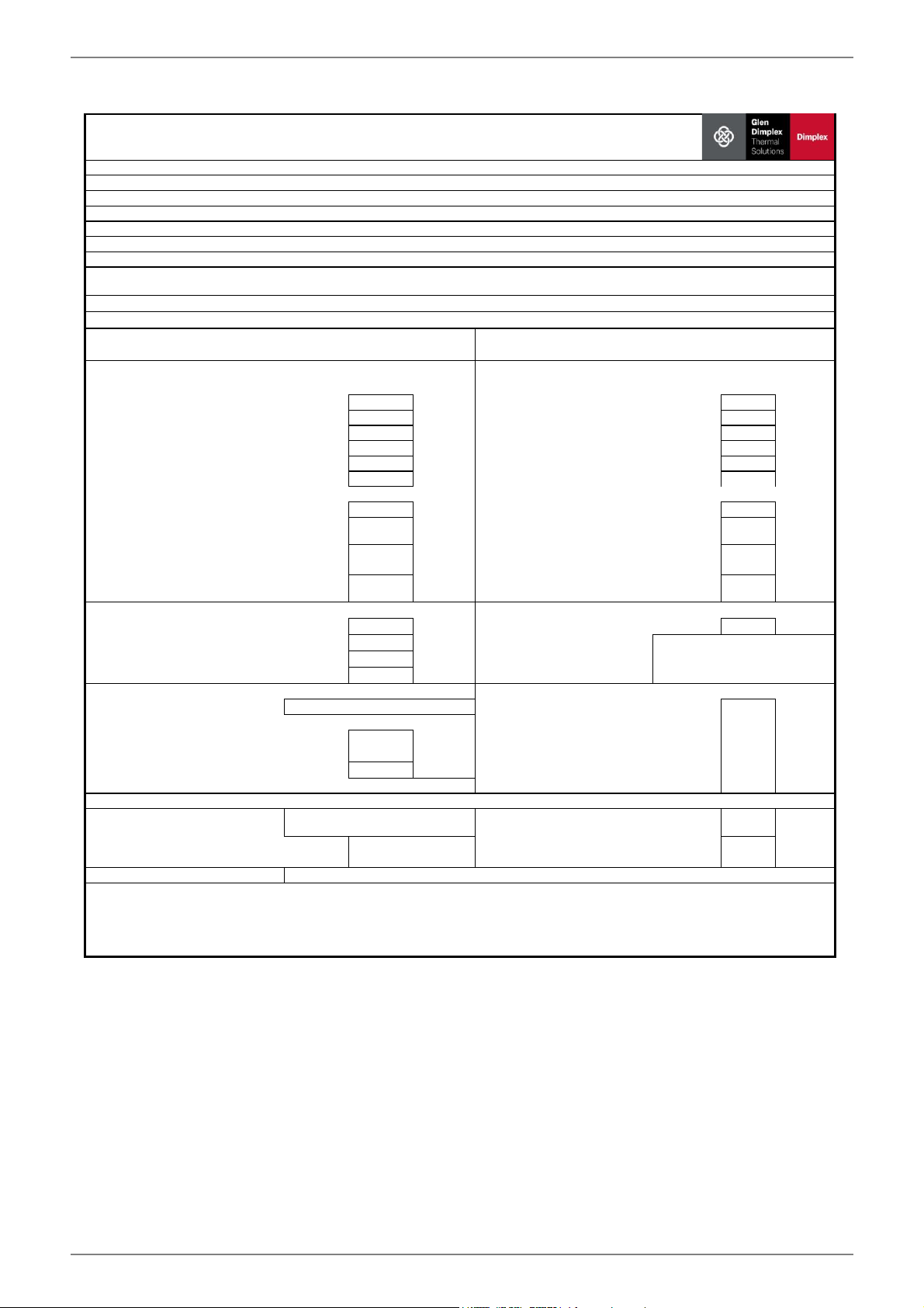
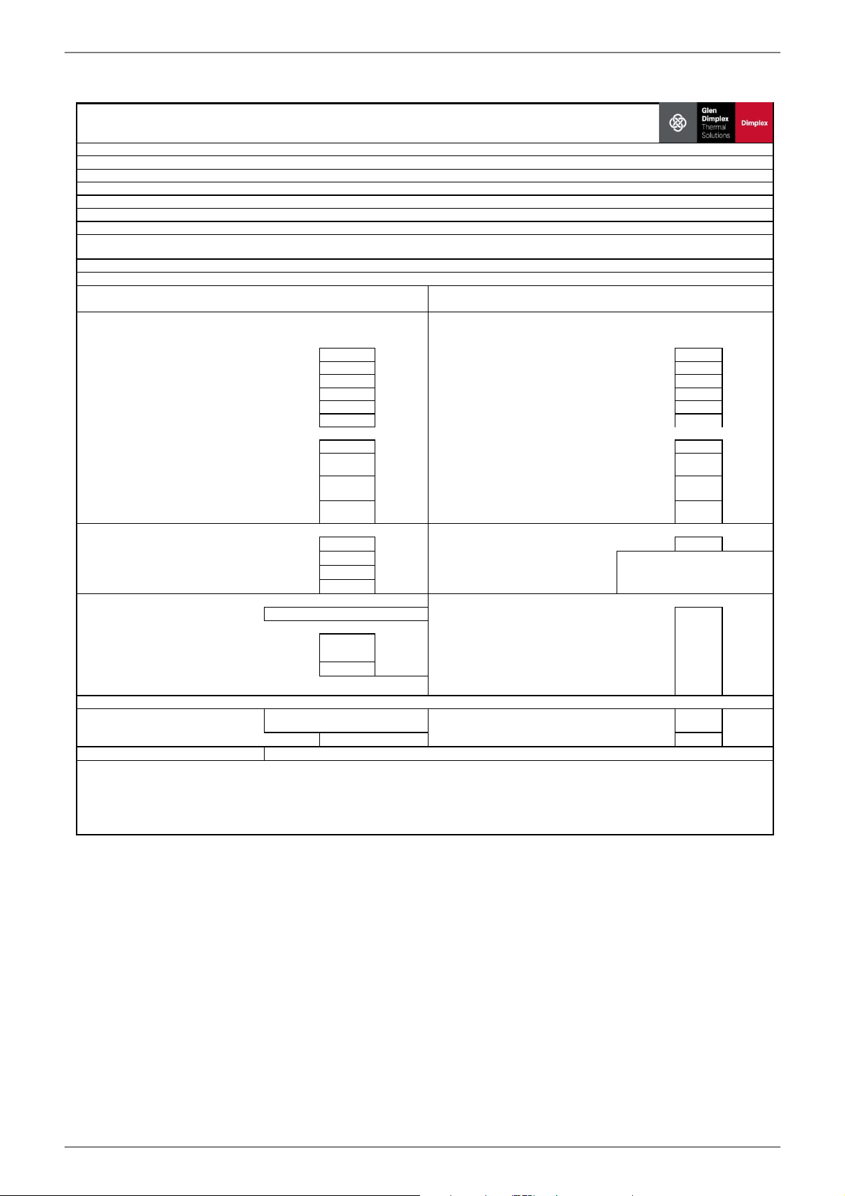
Information requirements for heat pump space heaters and heat pump combination heaters
ItemSymbolValueUnitItemSymbolValue
Unit
Tj = - 7°C
Pdh7,3kWTj = - 7°CCOPd2,99-
Tj = + 2°C
Pdh7,7kWTj = + 2°CCOPd3,65-
Tj = + 7°C
Pdh7,9kWTj = + 7°CCOPd4,17-
Tj = + 12°C
Pdh8,1kWTj = + 12°CCOPd4,81-
Tj = bivalent temperature
Pdh7,2kWTj = bivalent temperatureCOPd2,83-
Tj = operation limit temperature
Pdh7,2kWTj = operation limit temperature COPd2,83-
For air-to-water heat pumps
For air-to-water heat pumps:
Tj = -15°C (if TOL < -20°C)
Pdh7,2kWTj = -15°C (if TOL < -20°C)COPd2,83-
Bivalent temperature
Tbiv-10°C
For air-to-water heat pumps:
Operation limit temperature
TOL-10°C
Cycling interval capacity for heating
Pcych-kWCycling interval efficiencyCOPcyc--
Degradation co-efficient (**)
Cdh0,90-
Heating water operating limit
temperature
WTOL62°C
Power consumption in modes other than active mode
Supplementary heater
Off mode
POFF0,015kWRated heat output (*)Psup0kW
Thermostat-off mode
PTO0,020kWType of energy inputeletrical
Standby mode
PSB0,015kW
Crankcase heater modePCK0,000kW
Other items
Capacity control
fixed--
m³ /h
Sound power level, indoors/ outdoors
LWA46/-dB-1,9
m³ /h
Emissions of nitrogen oxides
NOx-mg/kWh
Declared load profile
-Water heating energy efficiencyηwh-%
Daily electricity consumption
Qelec-kWhDaily fuel consumptionQfuel-
kWh
Contact details
(**) If Cdh is not determined by measurement nthen the default degradation is Cdh = 0,9
(--) not applicable
For air-to-water heat pumps: Rated
air flow rate, outdoors
For water-/brine-to-water heat
pumps: Rated brine or water flow
rate, outdoor heat exchanger
Declared capacity for heating foer part load at indoor temperature 20°C and
outdoor temperature Tj
Declared coefficient of performance or primary energy ratio for part load at
indoor temperature 20 °C and outdoor temperature Tj
For heat pump combination heater:
Glen Dimplex Deutschland GmbH, Am Goldenen Feld 18, 95326 Kulmbach
(*) For heat pump space heaters and heat pump combination heaters, the rated output Prated is equal to the design load for heating Pdesignh, and the rated
heat output of a supplementary capacity for heating sup(Tj).
138
%
Heat pump combination heater
no
Parameters shall be declared for medium-temperature application, except for low-temperature heat pumps. For low- temperature heat pumps, parameters
shall be declared for low-temperature application.
Rated heat output (*)
Prated
7kW
Seasonal space heating energy
efficiency
ηs
Parameters shall be declared for average climate conditions:
Brine-to-water heat pump
yes
Low-temperature heat pump
no
Equipped with a supplementary heater
no
Model
SI 8TU
Air-to-water heat pump
no
Water-to-water heat pump
no
EN-14452235.66.22a · FD0106www.glendimplex.de
EnglishSI6TU-SI 18TU
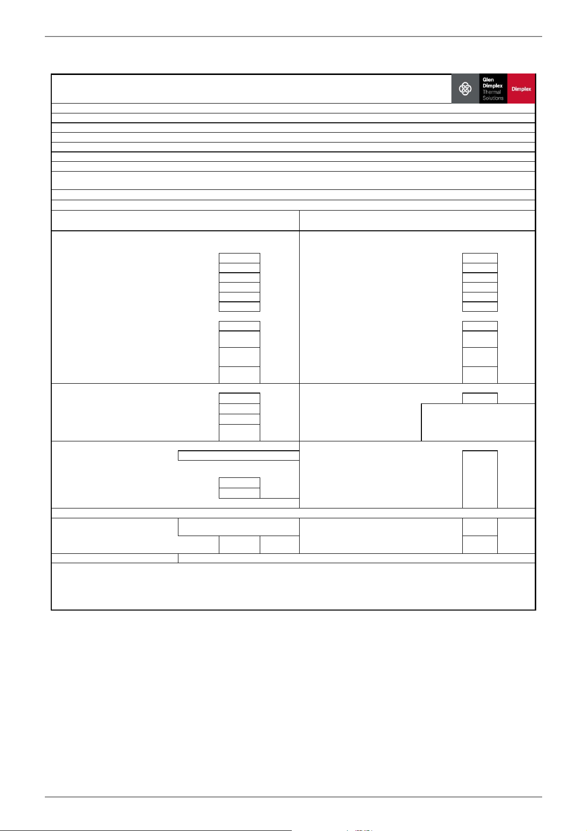
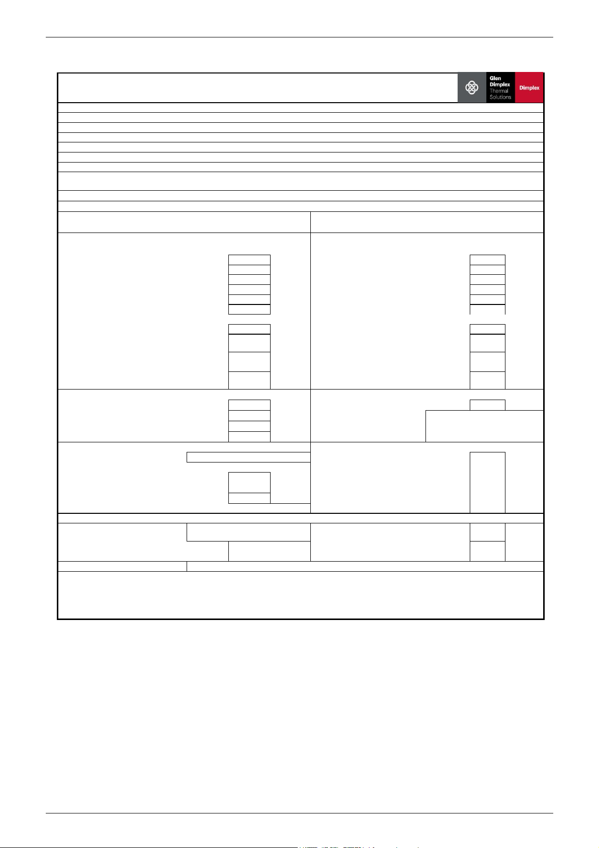
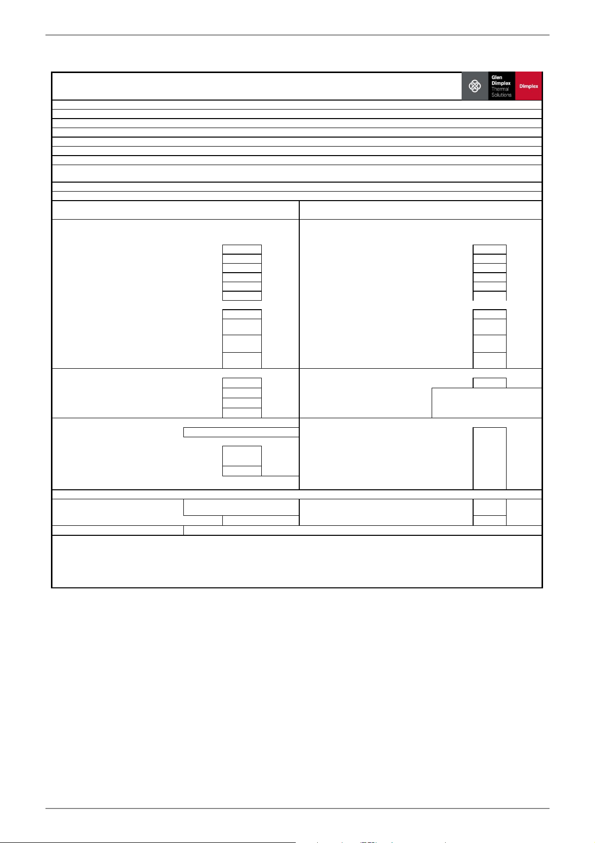
Information requirements for heat pump space heaters and heat pump combination heaters
ItemSymbolValueUnitItemSymbolValue
Unit
Tj = - 7°C
Pdh10,1kWTj = - 7°CCOPd3,06-
Tj = + 2°C
Pdh10,5kWTj = + 2°CCOPd3,73-
Tj = + 7°C
Pdh10,7kWTj = + 7°CCOPd4,27-
Tj = + 12°C
Pdh10,9kWTj = + 12°CCOPd4,96-
Tj = bivalent temperature
Pdh10,0kWTj = bivalent temperatureCOPd2,90-
Tj = operation limit temperature
Pdh10,0kWTj = operation limit temperature COPd2,90-
For air-to-water heat pumps
For air-to-water heat pumps:
Tj = -15°C (if TOL < -20°C)
Pdh10,0kWTj = -15°C (if TOL < -20°C)COPd2,90-
Bivalent temperature
Tbiv-10°C
For air-to-water heat pumps:
Operation limit temperature
TOL-10°C
Cycling interval capacity for heating
Pcych-kWCycling interval efficiencyCOPcyc--
Degradation co-efficient (**)
Cdh0,90-
Heating water operating limit
temperature
WTOL62°C
Power consumption in modes other than active mode
Supplementary heater
Off mode
POFF0,015kWRated heat output (*)Psup0kW
Thermostat-off mode
PTO0,020kWType of energy inputeletrical
Standby mode
PSB0,015kW
Crankcase heater modePCK0,000kW
Other items
Capacity control
fixed--
m³ /h
Sound power level, indoors/ outdoors
LWA47/-dB-2,6
m³ /h
Emissions of nitrogen oxides
NOx-mg/kWh
Declared load profile
-Water heating energy efficiencyηwh-%
Daily electricity consumption
Qelec-kWhDaily fuel consumptionQfuel-
kWh
Contact details
(**) If Cdh is not determined by measurement nthen the default degradation is Cdh = 0,9
(--) not applicable
For air-to-water heat pumps: Rated
air flow rate, outdoors
For water-/brine-to-water heat
pumps: Rated brine or water flow
rate, outdoor heat exchanger
Declared capacity for heating foer part load at indoor temperature 20°C and
outdoor temperature Tj
Declared coefficient of performance or primary energy ratio for part load at
indoor temperature 20 °C and outdoor temperature Tj
For heat pump combination heater:
Glen Dimplex Deutschland GmbH, Am Goldenen Feld 18, 95326 Kulmbach
(*) For heat pump space heaters and heat pump combination heaters, the rated output Prated is equal to the design load for heating Pdesignh, and the rated
heat output of a supplementary capacity for heating sup(Tj).
142
%
Heat pump combination heater
no
Parameters shall be declared for medium-temperature application, except for low-temperature heat pumps. For low- temperature heat pumps, parameters
shall be declared for low-temperature application.
Rated heat output (*)
Prated
10kW
Seasonal space heating energy
efficiency
ηs
Parameters shall be declared for average climate conditions:
Brine-to-water heat pump
yes
Low-temperature heat pump
no
Equipped with a supplementary heater
no
Model
SI 11TU
Air-to-water heat pump
no
Water-to-water heat pump
no
www.glendimplex.de452235.66.22a · FD0106EN-15
SI6TU-SI 18TU English
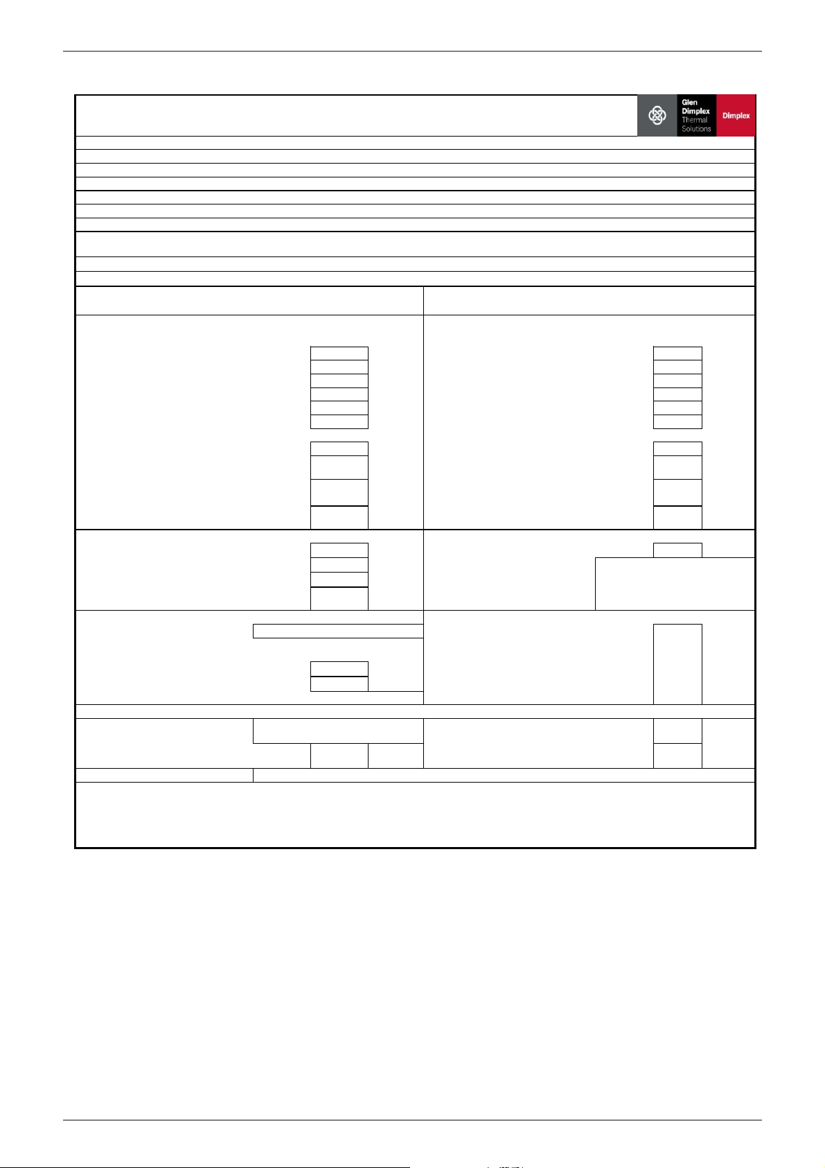
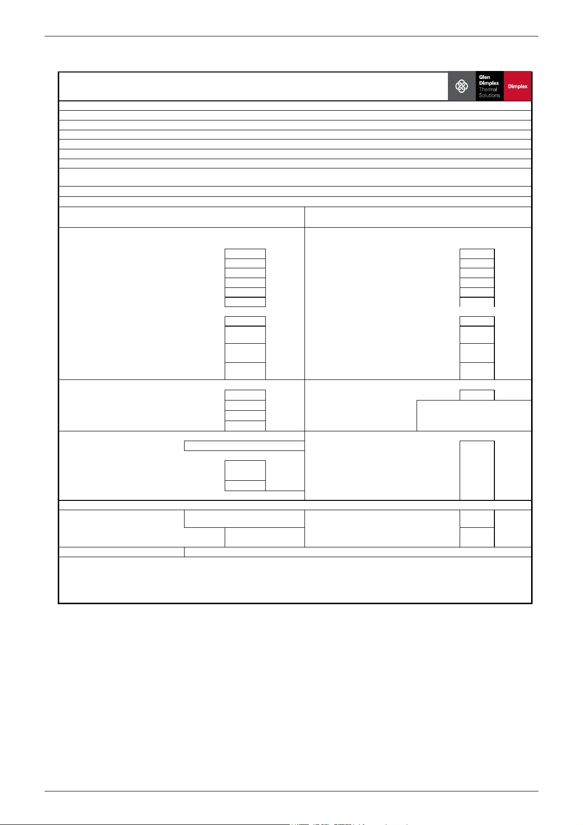
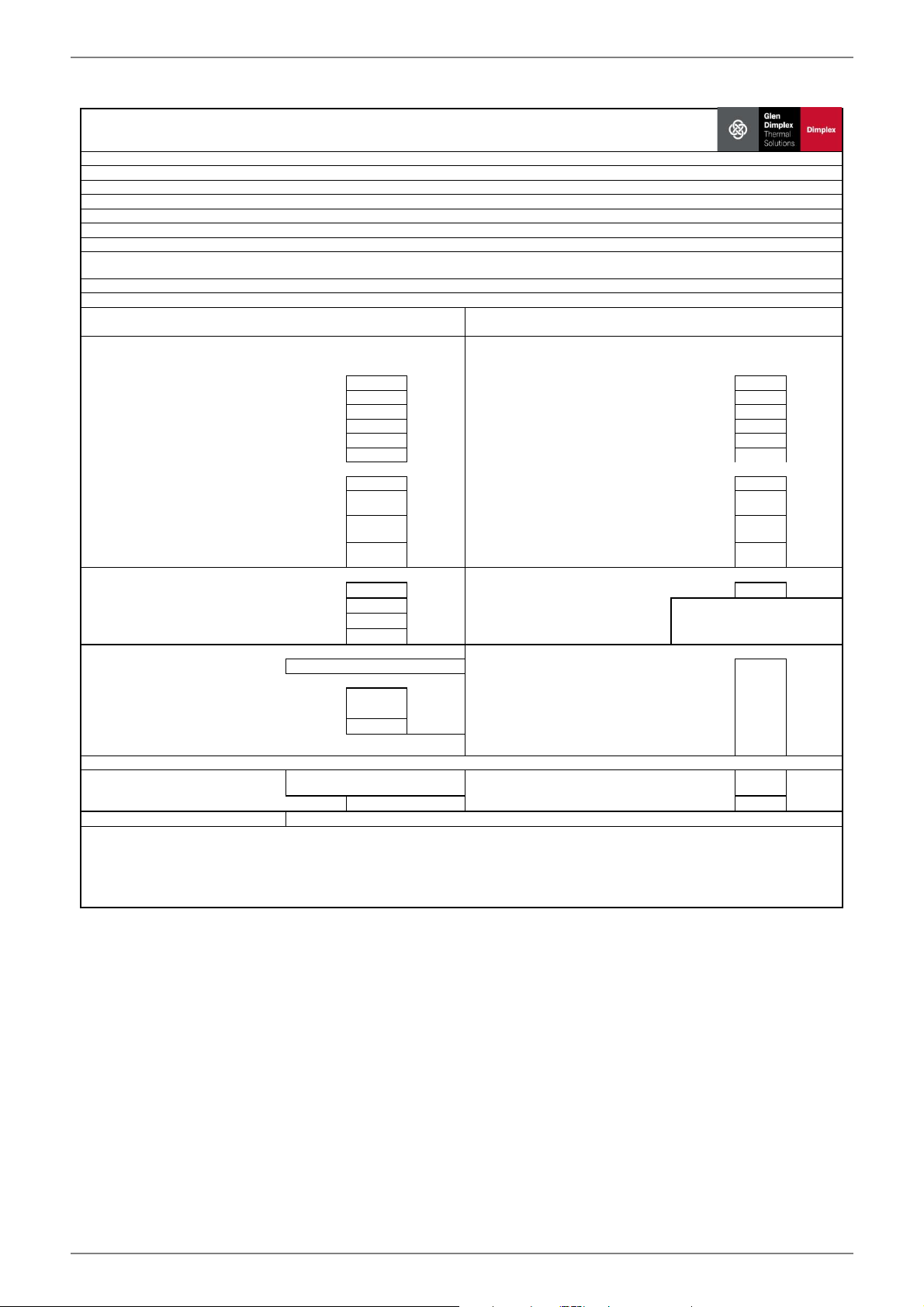
Information requirements for heat pump space heaters and heat pump combination heaters
ItemSymbolValueUnitItemSymbolValue
Unit
Tj = - 7°C
Pdh13,1kWTj = - 7°CCOPd3,29-
Tj = + 2°C
Pdh13,5kWTj = + 2°CCOPd3,93-
Tj = + 7°C
Pdh13,7kWTj = + 7°CCOPd4,43-
Tj = + 12°C
Pdh13,9kWTj = + 12°CCOPd5,06-
Tj = bivalent temperature
Pdh13,0kWTj = bivalent temperatureCOPd3,13-
Tj = operation limit temperature
Pdh13,0kWTj = operation limit temperature COPd3,13-
For air-to-water heat pumps
For air-to-water heat pumps:
Tj = -15°C (if TOL < -20°C)
Pdh13,0kWTj = -15°C (if TOL < -20°C)COPd3,13-
Bivalent temperature
Tbiv-10°C
For air-to-water heat pumps:
Operation limit temperature
TOL-10°C
Cycling interval capacity for heating
Pcych-kWCycling interval efficiencyCOPcyc--
Degradation co-efficient (**)
Cdh0,90-
Heating water operating limit
temperature
WTOL62°C
Power consumption in modes other than active mode
Supplementary heater
Off mode
POFF0,015kWRated heat output (*)Psup0kW
Thermostat-off mode
PTO0,020kWType of energy inputeletrical
Standby mode
PSB0,015kW
Crankcase heater modePCK0,000kW
Other items
Capacity control
fixed--
m³ /h
Sound power level, indoors/ outdoors
LWA47/-dB-3,4
m³ /h
Emissions of nitrogen oxides
NOx-mg/kWh
Declared load profile
-Water heating energy efficiencyηwh-%
Daily electricity consumption
Qelec-kWhDaily fuel consumptionQfuel-
kWh
Contact details
(**) If Cdh is not determined by measurement nthen the default degradation is Cdh = 0,9
(--) not applicable
For air-to-water heat pumps: Rated
air flow rate, outdoors
For water-/brine-to-water heat
pumps: Rated brine or water flow
rate, outdoor heat exchanger
Declared capacity for heating foer part load at indoor temperature 20°C and
outdoor temperature Tj
Declared coefficient of performance or primary energy ratio for part load at
indoor temperature 20 °C and outdoor temperature Tj
For heat pump combination heater:
Glen Dimplex Deutschland GmbH, Am Goldenen Feld 18, 95326 Kulmbach
(*) For heat pump space heaters and heat pump combination heaters, the rated output Prated is equal to the design load for heating Pdesignh, and the rated
heat output of a supplementary capacity for heating sup(Tj).
150
%
Heat pump combination heater
no
Parameters shall be declared for medium-temperature application, except for low-temperature heat pumps. For low- temperature heat pumps, parameters
shall be declared for low-temperature application.
Rated heat output (*)
Prated
13kW
Seasonal space heating energy
efficiency
ηs
Parameters shall be declared for average climate conditions:
Brine-to-water heat pump
yes
Low-temperature heat pump
no
Equipped with a supplementary heater
no
Model
SI 14TU
Air-to-water heat pump
no
Water-to-water heat pump
no
EN-16452235.66.22a · FD0106www.glendimplex.de
EnglishSI6TU-SI 18TU
Information requirements for heat pump space heaters and heat pump combination heaters
ItemSymbolValueUnitItemSymbolValue
Unit
Tj = - 7°C
Pdh16,6kWTj = - 7°CCOPd3,05-
Tj = + 2°C
Pdh17,0kWTj = + 2°CCOPd3,66-
Tj = + 7°C
Pdh17,3kWTj = + 7°CCOPd4,15-
Tj = + 12°C
Pdh17,5kWTj = + 12°CCOPd4,77-
Tj = bivalent temperature
Pdh16,5kWTj = bivalent temperatureCOPd2,90-
Tj = operation limit temperature
Pdh16,5kWTj = operation limit temperature COPd2,90-
For air-to-water heat pumps
For air-to-water heat pumps:
Tj = -15°C (if TOL < -20°C)
Pdh16,5kWTj = -15°C (if TOL < -20°C)COPd2,90-
Bivalent temperature
Tbiv-10°C
For air-to-water heat pumps:
Operation limit temperature
TOL-10°C
Cycling interval capacity for heating
Pcych-kWCycling interval efficiencyCOPcyc--
Degradation co-efficient (**)
Cdh0,90-
Heating water operating limit
temperature
WTOL62°C
Power consumption in modes other than active mode
Supplementary heater
Off mode
POFF0,015kWRated heat output (*)Psup0kW
Thermostat-off mode
PTO0,020kWType of energy inputeletrical
Standby mode
PSB0,015kW
Crankcase heater modePCK0,000kW
Other items
Capacity control
fixed--
m³ /h
Sound power level, indoors/ outdoors
LWA50/-dB-4,0
m³ /h
Emissions of nitrogen oxides
NOx-mg/kWh
Declared load profile
-Water heating energy efficiencyηwh-%
Daily electricity consumption
Qelec-kWhDaily fuel consumptionQfuel-
kWh
Contact details
(**) If Cdh is not determined by measurement nthen the default degradation is Cdh = 0,9
(--) not applicable
For air-to-water heat pumps: Rated
air flow rate, outdoors
For water-/brine-to-water heat
pumps: Rated brine or water flow
rate, outdoor heat exchanger
Declared capacity for heating foer part load at indoor temperature 20°C and
outdoor temperature Tj
Declared coefficient of performance or primary energy ratio for part load at
indoor temperature 20 °C and outdoor temperature Tj
For heat pump combination heater:
Glen Dimplex Deutschland GmbH, Am Goldenen Feld 18, 95326 Kulmbach
(*) For heat pump space heaters and heat pump combination heaters, the rated output Prated is equal to the design load for heating Pdesignh, and the rated
heat output of a supplementary capacity for heating sup(Tj).
140
%
Heat pump combination heater
no
Parameters shall be declared for medium-temperature application, except for low-temperature heat pumps. For low- temperature heat pumps, parameters
shall be declared for low-temperature application.
Rated heat output (*)
Prated
17kW
Seasonal space heating energy
efficiency
ηs
Parameters shall be declared for average climate conditions:
Brine-to-water heat pump
yes
Low-temperature heat pump
no
Equipped with a supplementary heater
no
Model
SI 18TU
Air-to-water heat pump
no
Water-to-water heat pump
no
www.glendimplex.de452235.66.22a · FD0106FR-1
SI6TU-SI 18TUFrançais
Table des matières
1Consignes de sécurité................................................................................................................................FR-2
1.1Symboles et identification............................................................................................................................................FR-2
1.3Dispositions légales et directives................................................................................................................................FR-2
1.4Utilisation de la pompe à chaleur pour économiser de l'énergie.....................................................................FR-2
2Utilisation de la pompe à chaleur............................................................................................................FR-2
3Appareil de base..........................................................................................................................................FR-3
4.3Système de gestion technique des bâtiments......................................................................................................FR-3
7.2Branchement côté installation de chauffage.........................................................................................................FR-5
7.3Raccordement côté source de chaleur....................................................................................................................FR-5
7.4Sonde de température...................................................................................................................................................FR-6
8Mise en service.............................................................................................................................................FR-8
8.3Procédures à suivre lors de la mise en service.......................................................................................................FR-8
9.2Nettoyage côté chauffage............................................................................................................................................FR-9
9.3Nettoyage côté source de chaleur.............................................................................................................................FR-9
10Défaillances / recherche de pannes.......................................................................................................FR-9
11Mise hors service/ mise au rebut............................................................................................................FR-9
12Informations sur les appareils...............................................................................................................FR-10
13Informations sur le
produit conformément au Règlmenet (UE) n° 813/2013, annexe II, tableau 2........................FR-13
7Conforme aux dispositions de sécurité européennes888
8Autres caractéristiques techniques
8.1Eau de chauffage dans l’appareil protégée du gel 9ouiouioui
8.2Surpression de service max. (source de chaleur/dissipation thermique) bar3,03,03,0
1.En cas de besoin, la plage d'exploitation peut être élargie jusqu'à une température d'entrée de l'eau glycolée de -10 °C. Dans ce cas, la concentration minimale en eau glycolée
doit être fixée à 30 %. (température de gel -17 °C). À une température de l'eau glycolée comprise entre -10 °C et -5 °C, température départ croissante de 55 °C à 62 °C.
2.Exploitation possible jusqu'à une température d'entrée de l'eau glycolée de +35 °C. À une température de l'eau glycolée comprise entre +25 °C et +35 °C, température départ
décroissante de 62 °C à 55 °C.
3.Ces indications caractérisent la taille et le rendement de l'installation selon EN 14511. Le point de bivalence et la régulation sont à prendre en compte pour des considérations
économiques et énergétiques. Ici, B0W55 signifie par ex. : température de la source de chaleur 0 °C et température départ de l'eau de chauffage 55 °C. Ces données sont
uniquement atteintes avec des échangeurs thermiques propres. Des remarques sur l'entretien, la mise en service et le fonctionnement sont mentionnées aux paragraphes
correspondants des instructions de montage et d'utilisation.
4.Les valeurs sonores indiquées sont uniquement valables en cas d'exploitation sans pieds. En cas d'utilisation des pieds, le niveau sonore peut augmenter de 3db (A) max.
5.Le niveau de pression sonore indiqué correspond au bruit de fonctionnement de la pompe à chaleur en mode chauffage à une température aller de 35 °C. Le niveau de puis-
sance sonore indiqué est celui d’une propagation de champ libre. Selon le lieu d'installation, la valeur mesurée peut varier de 16 db(A) max.
6.Tenir compte de la place nécessaire plus importante pour le raccordement des tuyaux, la commande et l’entretien.
7.à joint plat
8.Voir déclaration de conformité CE
9.Le circulateur du circuit de chauffage et le gestionnaire de la pompe à chaleur doivent toujours être prêts à fonctionner.
1Désignation technique et commercialeSI14TUSI18TU
2Forme
2.1Version Universelle Universelle
2.2Régulateurinterneinterne
2.3Calorimètreintégréintégré
2.4Emplacement / degré de protection selon EN 60 529en intérieur / IP 21en intérieur / IP 21
2.5Niveaux de puissance11
3Plages d'utilisation
3.1Circuit de départ de l'eau de chauffage 1°C 20 à 62 ±2 20 bis 62 ±2
3.2Eau glycolée (source de chaleur)°C
Produit antigel
Concentration minimale en eau glycolée (température de gel -13 °C)1
de -51 à +252
monoéthylène glycol
25 %1
de -51 à +252
monoéthylène glycol
25 %1
4Puissance / débit 3
4.1Débit d’eau de chauffage en cas de différence de pression interne
max: (EN14511) m³/h / Pa
min:m³/h / Pa
2,4 / 10700
1,2 / 2700
3,0 / 18000
1,5 / 4500
4.2Capacité thermique / coefficient de performanceEN 14511EN 14511
pour B-5 / W45 kW / ---11,6 / 3,314,9 / 3,2
pour B0 / W55 kW / ---12,8 / 3,016,5 / 2,9
pour B0 / W45 kW / ---13,3 / 3,817,0 / 3,6
pour B0 / W35 kW / ---13,9 / 5,017,5 / 4,7
4.3Niveau de puissance sonore selon EN 12102 4dB(A)4750
4.4Niveau de pression acoustique à 1m de distance45dB(A)3538
4.5Débit d'eau glycolée avec difféence de pression interne
source de chaleurm³/h / Pa3,4 / 140004,3 / 21500
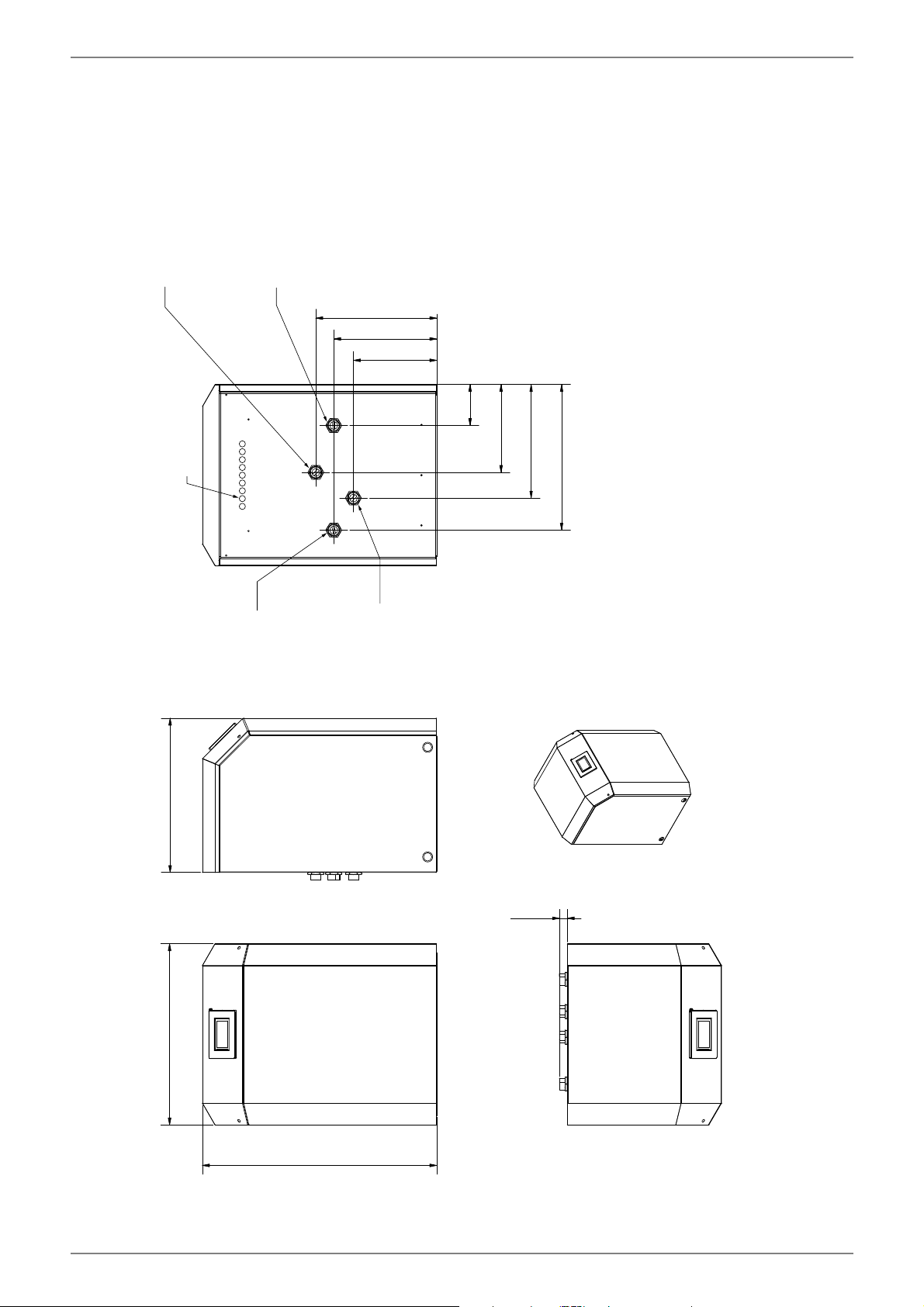
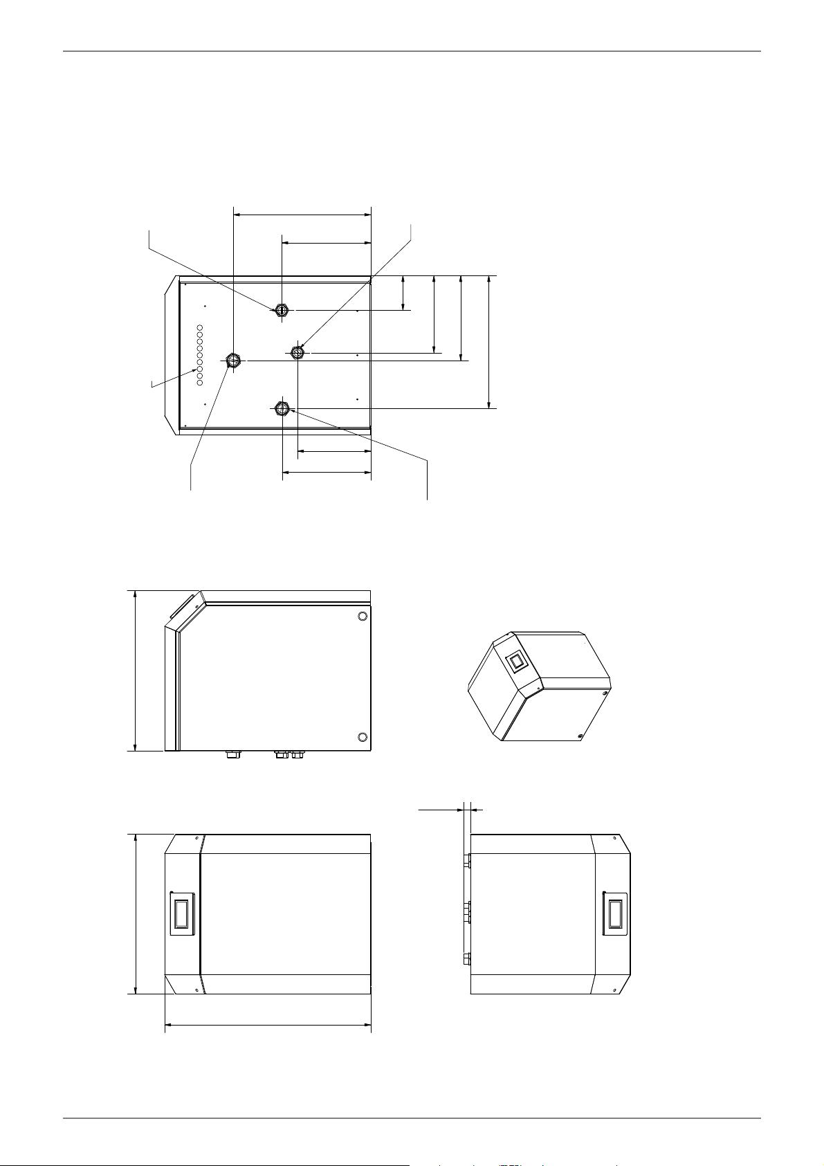
5Dimensions / raccordements et poids
5.1Dimensions de l’appareil sans raccordements pieds sont 6H x l x L cm840 x 650 x 555840 x 650 x 655
5.2Raccordements de l’appareil de chauffagepoucesFiletage ext. 1 1/4"7Filetage ext. 1 1/4“ AG7
5.3Raccordements de l’appareil à la source de chaleurpoucesFiletage ext. 1 1/4"7Filetage ext. 1 1/2“ AG7
5.4Poids de/des unités de transport, emballage compriskg140163
5.5Fluide frigorigène / poids total au remplissagetype / kgR410A / 4,4R410A / 5,2
7Conforme aux dispositions de sécurité européennes88
8Autres caractéristiques techniques
8.1Eau de chauffage dans l’appareil protégée du gel 9ouioui
8.2Surpression de service max. (source de chaleur/dissipation thermique) bar3,03,0
1.En cas de besoin, la plage d'exploitation peut être élargie jusqu'à une température d'entrée de l'eau glycolée de -10 °C. Dans ce cas, la concentration minimale en eau glycolée
doit être fixée à 30 %. (température de gel -17 °C). À une température de l'eau glycolée comprise entre -10 °C et -5 °C, température départ croissante de 55 °C à 62 °C.
2.Exploitation possible jusqu'à une température d'entrée de l'eau glycolée de +35 °C. À une température de l'eau glycolée comprise entre +25 °C et +35 °C, température départ
décroissante de 62 °C à 55 °C.
3.Ces indications caractérisent la taille et le rendement de l'installation selon EN 14511. Le point de bivalence et la régulation sont à prendre en compte pour des considérations
économiques et énergétiques. Ici, B0W55 signifie par ex. : température de la source de chaleur 0 °C et température départ de l'eau de chauffage 55 °C. Ces données sont
uniquement atteintes avec des échangeurs thermiques propres. Des remarques sur l'entretien, la mise en service et le fonctionnement sont mentionnées aux paragraphes
correspondants des instructions de montage et d'utilisation.
4.Les valeurs sonores indiquées sont uniquement valables en cas d'exploitation sans pieds. En cas d'utilisation des pieds, le niveau sonore peut augmenter de 3db (A) max.
5.Le niveau de pression sonore indiqué correspond au bruit de fonctionnement de la pompe à chaleur en mode chauffage à une température aller de 35 °C. Le niveau de puis-
sance sonore indiqué est celui d’une propagation de champ libre. Selon le lieu d'installation, la valeur mesurée peut varier de 16 db(A) max.
6.Tenir compte de la place nécessaire plus importante pour le raccordement des tuyaux, la commande et l’entretien.
7.à joint plat
8.Voir déclaration de conformité CE
9.Le circulateur du circuit de chauffage et le gestionnaire de la pompe à chaleur doivent toujours être prêts à fonctionner.
Pour les dispositifs de chauffage mixtes par pompe à chaleur
Profil de soutirage déclaré
-
Efficacité énergétique pour le chauffage de
l’eau
ηwh-%
Consommation journalière d’électricité
Qelec-kWhConsommation journalière de combustibleQfuel-kWh
Coordonnées de contact
(**) Si le Cdh n’est pas déterminé par des mesures, le coefficient de dégradation par défaut est Cdh = 0,9.
(--) non applicable
(*) Pour les dispositifs de chauffage des locaux par pompe à chaleur et les dispositifs de chauffage mixtes par pompe à chaleur, la puissance thermique nominale Prated est
égale à la charge calorifique nominale Pdesignh et la puissance thermique nominale d’un dispositif de chauffage d’appoint Psup est égale à la puissance calorifique d’appoint
sup(Tj).
non
Pompes à chaleur basse température:
Glen Dimplex Deutschland GmbH, Am Goldenen Feld 18, 95326 Kulmbach
non
Pour les pompes à chaleur air-eau: débit d’air
nominal, à l’extérieur
Pour les pompes à chaleur eau-eau ou eau
glycolée-eau: débit nominal d’eau glycolée ou
d’eau, échangeur thermique extérieur
Dispositif de chauffage mixte par pompe à chaleur:
non
Les paramètres sont déclarés pour l’application à moyenne température, excepté pour les pompes à chaleur basse température. Pour les pompes à chaleur basse
température, les paramètres sont déclarés pour l’application à basse température.
Puissance thermique nominale (*)
Prated
%kW6
134
Exigences d’information pour les dispositifs de chauffage des locaux par pompe à chaleur
Puissance calorifique déclarée à charge partielle pour une température intérieure de 20
°C et une température extérieure Tj
Coefficient de performance déclaré ou coefficient sur énergie primaire déclaré à
charge partielle pour une température intérieure de 20 °C et une température
extérieure Tj
ηs
Équipée d’un dispositif de chauffage d’appoint:
Les paramètres sont déclarés pour les conditions climatiques moyenne:
Modèle(s):
SI 6TU
Pompes à chaleur air-eau:
non
Pompes à chaleur eau-eau:
non
oui
et les dispositifs de chauffage mixtes par pompe à chaleur
Pour les dispositifs de chauffage mixtes par pompe à chaleur
Profil de soutirage déclaré
-
Efficacité énergétique pour le chauffage de
l’eau
ηwh-%
Consommation journalière d’électricité
Qelec-kWhConsommation journalière de combustibleQfuel-kWh
Coordonnées de contact
(**) Si le Cdh n’est pas déterminé par des mesures, le coefficient de dégradation par défaut est Cdh = 0,9.
(--) non applicable
(*) Pour les dispositifs de chauffage des locaux par pompe à chaleur et les dispositifs de chauffage mixtes par pompe à chaleur, la puissance thermique nominale Prated est
égale à la charge calorifique nominale Pdesignh et la puissance thermique nominale d’un dispositif de chauffage d’appoint Psup est égale à la puissance calorifique d’appoint
sup(Tj).
non
Pompes à chaleur basse température:
Glen Dimplex Deutschland GmbH, Am Goldenen Feld 18, 95326 Kulmbach
non
Pour les pompes à chaleur air-eau: débit d’air
nominal, à l’extérieur
Pour les pompes à chaleur eau-eau ou eau
glycolée-eau: débit nominal d’eau glycolée ou
d’eau, échangeur thermique extérieur
Dispositif de chauffage mixte par pompe à chaleur:
non
Les paramètres sont déclarés pour l’application à moyenne température, excepté pour les pompes à chaleur basse température. Pour les pompes à chaleur basse
température, les paramètres sont déclarés pour l’application à basse température.
Puissance thermique nominale (*)
Prated
%kW7
138
Exigences d’information pour les dispositifs de chauffage des locaux par pompe à chaleur
Puissance calorifique déclarée à charge partielle pour une température intérieure de 20
°C et une température extérieure Tj
Coefficient de performance déclaré ou coefficient sur énergie primaire déclaré à
charge partielle pour une température intérieure de 20 °C et une température
extérieure Tj
ηs
Équipée d’un dispositif de chauffage d’appoint:
Les paramètres sont déclarés pour les conditions climatiques moyenne:
Modèle(s):
SI 8TU
Pompes à chaleur air-eau:
non
Pompes à chaleur eau-eau:
non
oui
et les dispositifs de chauffage mixtes par pompe à chaleur
Pour les dispositifs de chauffage mixtes par pompe à chaleur
Profil de soutirage déclaré
-
Efficacité énergétique pour le chauffage de
l’eau
ηwh-%
Consommation journalière d’électricité
Qelec-kWhConsommation journalière de combustibleQfuel-kWh
Coordonnées de contact
(**) Si le Cdh n’est pas déterminé par des mesures, le coefficient de dégradation par défaut est Cdh = 0,9.
(--) non applicable
(*) Pour les dispositifs de chauffage des locaux par pompe à chaleur et les dispositifs de chauffage mixtes par pompe à chaleur, la puissance thermique nominale Prated est
égale à la charge calorifique nominale Pdesignh et la puissance thermique nominale d’un dispositif de chauffage d’appoint Psup est égale à la puissance calorifique d’appoint
sup(Tj).
non
Pompes à chaleur basse température:
Glen Dimplex Deutschland GmbH, Am Goldenen Feld 18, 95326 Kulmbach
non
Pour les pompes à chaleur air-eau: débit d’air
nominal, à l’extérieur
Pour les pompes à chaleur eau-eau ou eau
glycolée-eau: débit nominal d’eau glycolée ou
d’eau, échangeur thermique extérieur
Dispositif de chauffage mixte par pompe à chaleur:
non
Les paramètres sont déclarés pour l’application à moyenne température, excepté pour les pompes à chaleur basse température. Pour les pompes à chaleur basse
température, les paramètres sont déclarés pour l’application à basse température.
Puissance thermique nominale (*)
Prated
%kW10
142
Exigences d’information pour les dispositifs de chauffage des locaux par pompe à chaleur
Puissance calorifique déclarée à charge partielle pour une température intérieure de 20
°C et une température extérieure Tj
Coefficient de performance déclaré ou coefficient sur énergie primaire déclaré à
charge partielle pour une température intérieure de 20 °C et une température
extérieure Tj
ηs
Équipée d’un dispositif de chauffage d’appoint:
Les paramètres sont déclarés pour les conditions climatiques moyenne:
Modèle(s):
SI 11TU
Pompes à chaleur air-eau:
non
Pompes à chaleur eau-eau:
non
oui
et les dispositifs de chauffage mixtes par pompe à chaleur
Pour les dispositifs de chauffage mixtes par pompe à chaleur
Profil de soutirage déclaré
-
Efficacité énergétique pour le chauffage de
l’eau
ηwh-%
Consommation journalière d’électricité
Qelec-kWhConsommation journalière de combustibleQfuel-kWh
Coordonnées de contact
(**) Si le Cdh n’est pas déterminé par des mesures, le coefficient de dégradation par défaut est Cdh = 0,9.
(--) non applicable
(*) Pour les dispositifs de chauffage des locaux par pompe à chaleur et les dispositifs de chauffage mixtes par pompe à chaleur, la puissance thermique nominale Prated est
égale à la charge calorifique nominale Pdesignh et la puissance thermique nominale d’un dispositif de chauffage d’appoint Psup est égale à la puissance calorifique d’appoint
sup(Tj).
non
Pompes à chaleur basse température:
Glen Dimplex Deutschland GmbH, Am Goldenen Feld 18, 95326 Kulmbach
non
Pour les pompes à chaleur air-eau: débit d’air
nominal, à l’extérieur
Pour les pompes à chaleur eau-eau ou eau
glycolée-eau: débit nominal d’eau glycolée ou
d’eau, échangeur thermique extérieur
Dispositif de chauffage mixte par pompe à chaleur:
non
Les paramètres sont déclarés pour l’application à moyenne température, excepté pour les pompes à chaleur basse température. Pour les pompes à chaleur basse
température, les paramètres sont déclarés pour l’application à basse température.
Puissance thermique nominale (*)
Prated
%kW13
150
Exigences d’information pour les dispositifs de chauffage des locaux par pompe à chaleur
Puissance calorifique déclarée à charge partielle pour une température intérieure de 20
°C et une température extérieure Tj
Coefficient de performance déclaré ou coefficient sur énergie primaire déclaré à
charge partielle pour une température intérieure de 20 °C et une température
extérieure Tj
ηs
Équipée d’un dispositif de chauffage d’appoint:
Les paramètres sont déclarés pour les conditions climatiques moyenne:
Modèle(s):
SI 14TU
Pompes à chaleur air-eau:
non
Pompes à chaleur eau-eau:
non
oui
et les dispositifs de chauffage mixtes par pompe à chaleur
Pour les dispositifs de chauffage mixtes par pompe à chaleur
Profil de soutirage déclaré
-
Efficacité énergétique pour le chauffage de
l’eau
ηwh-%
Consommation journalière d’électricité
Qelec-kWhConsommation journalière de combustibleQfuel-kWh
Coordonnées de contact
(**) Si le Cdh n’est pas déterminé par des mesures, le coefficient de dégradation par défaut est Cdh = 0,9.
(--) non applicable
(*) Pour les dispositifs de chauffage des locaux par pompe à chaleur et les dispositifs de chauffage mixtes par pompe à chaleur, la puissance thermique nominale Prated est
égale à la charge calorifique nominale Pdesignh et la puissance thermique nominale d’un dispositif de chauffage d’appoint Psup est égale à la puissance calorifique d’appoint
sup(Tj).
non
Pompes à chaleur basse température:
Glen Dimplex Deutschland GmbH, Am Goldenen Feld 18, 95326 Kulmbach
non
Pour les pompes à chaleur air-eau: débit d’air
nominal, à l’extérieur
Pour les pompes à chaleur eau-eau ou eau
glycolée-eau: débit nominal d’eau glycolée ou
d’eau, échangeur thermique extérieur
Dispositif de chauffage mixte par pompe à chaleur:
non
Les paramètres sont déclarés pour l’application à moyenne température, excepté pour les pompes à chaleur basse température. Pour les pompes à chaleur basse
température, les paramètres sont déclarés pour l’application à basse température.
Puissance thermique nominale (*)
Prated
%kW17
140
Exigences d’information pour les dispositifs de chauffage des locaux par pompe à chaleur
Puissance calorifique déclarée à charge partielle pour une température intérieure de 20
°C et une température extérieure Tj
Coefficient de performance déclaré ou coefficient sur énergie primaire déclaré à
charge partielle pour une température intérieure de 20 °C et une température
extérieure Tj
ηs
Équipée d’un dispositif de chauffage d’appoint:
Les paramètres sont déclarés pour les conditions climatiques moyenne:
Modèle(s):
SI 18TU
Pompes à chaleur air-eau:
non
Pompes à chaleur eau-eau:
non
oui
et les dispositifs de chauffage mixtes par pompe à chaleur
Gebruikershandleiding.com neemt misbruik van zijn services uitermate serieus. U kunt hieronder aangeven waarom deze vraag ongepast is. Wij controleren de vraag en zonodig wordt deze verwijderd.
Product:
Spelregels forum
Om tot zinvolle vragen te komen hanteren wij de volgende spelregels:
lees eerst de handleiding door;
controleer of uw vraag al eerder door iemand anders is gesteld;
probeer uw vraag zo duidelijk mogelijk te stellen;
heeft u een probleem en al geprobeerd om dit op te lossen, vermeld dit erbij aub;
heeft u een oplossing gekregen van een bezoeker dan horen wij dat graag in dit forum;
wilt u een reactie geven op een vraag of antwoord, gebruik dan niet dit formulier maar klik op de knop 'reageer op deze vraag';
uw vraag wordt direct op de website gezet; vermijd daarom persoonlijke gegevens in te vullen;
Belangrijk! Als er een antwoord wordt gegeven op uw vraag, dan is het voor de gever van het antwoord nuttig om te weten als u er wel (of niet) mee geholpen bent! Wij vragen u dus ook te reageren op een antwoord.
Belangrijk! Antwoorden worden ook per e-mail naar abonnees gestuurd. Laat uw emailadres achter op deze site, zodat u op de hoogte blijft. U krijgt dan ook andere vragen en antwoorden te zien.
Abonneren
Abonneer u voor het ontvangen van emails voor uw Dimplex SI 11TU bij:
nieuwe vragen en antwoorden
nieuwe handleidingen
U ontvangt een email met instructies om u voor één of beide opties in te schrijven.
Ontvang uw handleiding per email
Vul uw emailadres in en ontvang de handleiding van Dimplex SI 11TU in de taal/talen: Duits, Engels, Frans als bijlage per email.
De handleiding is 2.36 mb groot.
U ontvangt de handleiding per email binnen enkele minuten. Als u geen email heeft ontvangen, dan heeft u waarschijnlijk een verkeerd emailadres ingevuld of is uw mailbox te vol. Daarnaast kan het zijn dat uw internetprovider een maximum heeft aan de grootte per email. Omdat hier een handleiding wordt meegestuurd, kan het voorkomen dat de email groter is dan toegestaan bij uw provider.
Uw handleiding is per email verstuurd. Controleer uw email
Als u niet binnen een kwartier uw email met handleiding ontvangen heeft, kan het zijn dat u een verkeerd emailadres heeft ingevuld of dat uw emailprovider een maximum grootte per email heeft ingesteld die kleiner is dan de grootte van de handleiding.
Er is een email naar u verstuurd om uw inschrijving definitief te maken.
Controleer uw email en volg de aanwijzingen op om uw inschrijving definitief te maken
U heeft geen emailadres opgegeven
Als u de handleiding per email wilt ontvangen, vul dan een geldig emailadres in.
Uw vraag is op deze pagina toegevoegd
Wilt u een email ontvangen bij een antwoord en/of nieuwe vragen? Vul dan hier uw emailadres in.