EN-6
English
6.3
6.3 Electrical Connection
A standard four-core cable is used for connecting the heat pump
to the power supply.
The cable must be provided by the customer. The conductor
cross section is selected in accordance with the power consump-
tion of the heat pump (see Appendix Device Information) and the
applicable VDE (EN) and VNB regulations.
An all-pole disconnecting device with a contact gap of at least
3 mm (e.g. utility blocking contactor or power contactor) as well
as a 3-pole circuit breaker with common tripping for all external
conductors must be installed in the power supply (tripping current
in compliance with the Device Information).
Ensure that the incoming supply has a clockwise rotating field
when connecting multiphase devices.
Phase sequence: L1, L2, L3.
Ensure that there is a clockwise rotating field: Operating the compressor
in the wrong rotational direction could cause damage to the compressor.
The control voltage is supplied via the heat pump manager.
The heat pump manager has a 230 V AC / 50 Hz power supply.
Connect the controller in compliance with its own operating in-
structions (16 A fuse).
The control line (not included in scope of supply) is connected to
the heat pump manager using the two rectangular plug connec-
tors. Use the plug connector located on the base of the heat
pump adjacent to the cable gland in the base plate. More de-
tailed information can be found in the operating instructions of
the heat pump manager.
For detailed information, see Circuit Diagrams in the Appendix.
7 Start-UP
7.1 General Information
To ensure that start-up is performed correctly, it should only be
carried out by an after-sales service technician authorised by the
manufacturer. This may be a condition for extending the guaran-
tee (see Warranty Service).
7.2 Preparation
The following items need to be checked prior to start-up:
The heat pump must be fully connected, as described in
Chapter 6.
All valves that could impair the proper flow of the heating
water in the heating circuit must be open.
The air intake and air outlet paths must be clear.
The ventilator must turn in the direction indicated by the ar-
row.
The settings of the heat pump manager must be adapted to
the heating system in accordance with the controller’s oper-
ating instructions.
Ensure the condensate outflow functions.
7.3 Procedure
The heat pump is started up via the heat pump manager. Adjust-
ments should be made in compliance with the instructions.
If an overflow valve is fitted to maintain the minimum heat-
ing water flow rate, the valve must be adapted to the require-
ments of the heating system. Incorrect adjustment can lead to
faulty operation and increased energy consumption. We recom-
mend carrying out the following procedure to correctly adjust the
overflow valve:
Close all of the heating circuits that may also be closed during
operation (depending on the type of heat pump usage) so that
the most unfavorable operating state - with respect to the water
flow rate - is achieved. This normally means the heating circuits
of the rooms on the south and west sides of the building. At least
one heating circuit must remain open (e.g. bathroom).
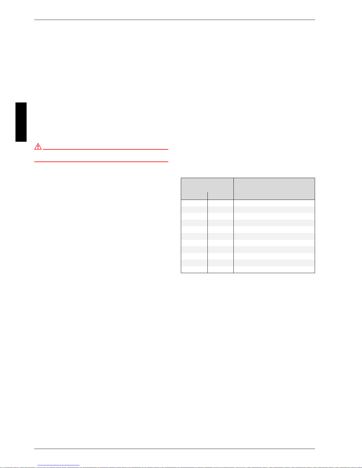
The overflow valve should be opened far enough to produce the
maximum temperature spread between the heating flow and re-
turn flow listed in the following table for the current heat source
temperature. The temperature spread should be measured as
close as possible to the heat pump. The heating element of mono
energy systems should be disconnected during start up.
At hot water temperatures under 7° C, start-up is not possible.
The water in the buffer tank must be heated to a minimum
of 18 °C with the second heat generator.
To ensure a problem-free start-up, the following procedure is to
be implemented:
1) Close all consumer circuits.
2) Ensure that the heat pump has the correct water flow.
3) Use the manager to select the automatic operating mode.
4) In the special functions menu, start the "Start-up" program.
5) Wait until a return temperature of at least 25 °C has been
reached.
6) Now slowly reopen the heating circuit valves in succession
so that the heating water flow is constantly raised by slightly
opening the respective heating circuit. The heating water
temperature in the buffer tank must not be allowed to drop
below 20°C during this process. This ensures that the heat
pump can be defrosted at any time.
7) When all heat circuits are fully open and a return tempera-
ture of at least 18° C is maintained, the heat pump start-up
is complete.
Heat source
temperature
Max. temperature spread
between heating flow and return
flow
From To
-20 °C -15 °C 4 K
-14 °C -10 °C 5 K
-9 °C -5 °C 6 K
-4 °C 0 °C 7 K
1 °C 5 °C 8 K
6 °C 10 °C 9 K
11 °C 15 °C 10 K
16 °C 20 °C 11 K
21 °C 25 °C 12 K
26 °C 30 °C 13 K
31 °C 35 °C 14 K