2.Diese Angaben charakterisieren die Größe und die Leistungsfähigkeit der Anlage nach EN 255 und EN14511. Für wirtschaftliche und energetische Betrachtungen sind weitere
Einflussgrößen, insbesondere Abtauverhalten, Bivalenzpunkt, und Regelung zu berücksichtigen. Dabei bedeuten z.B. A2 / W35: Außenlufttemperatur 2°C und Heizwasser-Vor-
The device is not suitable for operation with a frequency converter.
ATTENTION!
When transporting the heat pump, ensure that it is not tilted more than
45° (in any direction).
ATTENTION!
Do not restrict or block the area around the air intake or outlet.
ATTENTION!
Ensure that there is a clockwise rotating field: Operating the compressor
in the wrong rotational direction could cause damage to the compressor.
ATTENTION!
Never use cleaning agents containing sand, soda, acid or chloride as
these can damage the surfaces.
ATTENTION!
We recommend the installation of a suitable corrosion protection system
to prevent the formation of deposits (e.g. rust) in the condenser of the
heat pump.
ATTENTION!
Before opening the device, ensure that all circuits are isolated from the
power supply.
ATTENTION!
Any work on the heat pump may only be performed by authorised and
qualified after-sales service technicians.
1.2Intended Use
This device is only intended for use as specified by the manufac-
turer. Any other use beyond that intended by the manufacturer is
prohibited. This requires the user to abide by the manufacturers
product information. Please refrain from tampering with or alter-
ing the device.
1.3Legal Regulations and
Directives
This heat pump is designed for use in a domestic environment
according to Article 1, Paragraph 2 k) of EC directive 2006/42/EC
(machinery directive) and is thus subject to the requirements of
EC directive 2006/95/EC (low-voltage directive). It is thus also in-
tended for use by non-professionals for heating shops, offices
and other similar working environments, in agricultural establish-
ments and in hotels, guest houses and similar / other residential
buildings.
The construction and design of the heat pump complies with all
relevant EU directives, DIN/VDE regulations (see CE declaration
of conformity).
When connecting the heat pump to the power supply, the rele-
vant VDE, EN and IEC standards are to be fulfilled. Any further
connection requirements stipulated by local utility companies
must also be observed.
When connecting the heating system, all applicable regulations
must also be adhered to.
Persons, especially children, who are not capable of operating
the device safely due to their physical, sensory or mental abilities
or due to their inexperience or lack of knowledge, must not ope-
rate this device without supervision or instruction by the person in
charge.
Children must be supervised to ensure that they do not play with
the device.
1.4Energy-Efficient Use of the
Heat Pump
With the purchase of this heat pump you are helping to protect
the environment. A prerequisite for energy-efficient operation is
the correct design of the heat source system and heating system
(radiators and circulation pump).
It is particularly important for the efficiency of a heat pump to
keep the temperature difference between heating water and heat
source as small as possible. For this reason, it is advisable to de-
sign the heat source and heating system very carefully. A tem-
perature difference of approx. one Kelvin increases the
power consumption by around 2.5 %. When designing the
heating system, it should be borne in mind that special consum-
ers such as e.g. hot water preparation should also be considered
and dimensioned for low temperatures. Underfloor heating
systems (panel heating) are optimally suited for heat pump use
on account of the low flow temperatures (30°C to 40°C).
It is important to ensure that the heat exchangers are not con-
taminated during operation because this increases the tempera-
ture difference, in turn reducing the COP.
Correct adjustment of the heat pump manager is also important
for energy-efficient use of the heat pump. Further information can
be found in the heat pump manager operating instructions.
www.dimplex.deEN-3
English
3.1
2Purpose of the Heat
Pump
2.1Application
The air-to-water heat pump is to be used exclusively for the heat-
ing of heating water. It can be used in newly built or previously
existing heating systems.
The heat pump is suitable for mono energy and bivalent opera-
tion down to an external temperature of -25°C.
Proper defrosting of the evaporator is guaranteed by maintaining
a heating water return flow temperature of more than 18°C dur-
ing continuous operation.
The heat pump is not designed for the increased heat consump-
tion required when a building is being dried out. The additional
heat consumption should be met using special devices provided
by the customer. If a building is to be dried out in autumn or win-
ter, we recommend installing an additional heating element
(available as an accessory).
ATTENTION!
The device is not suitable for operation with a frequency converter.
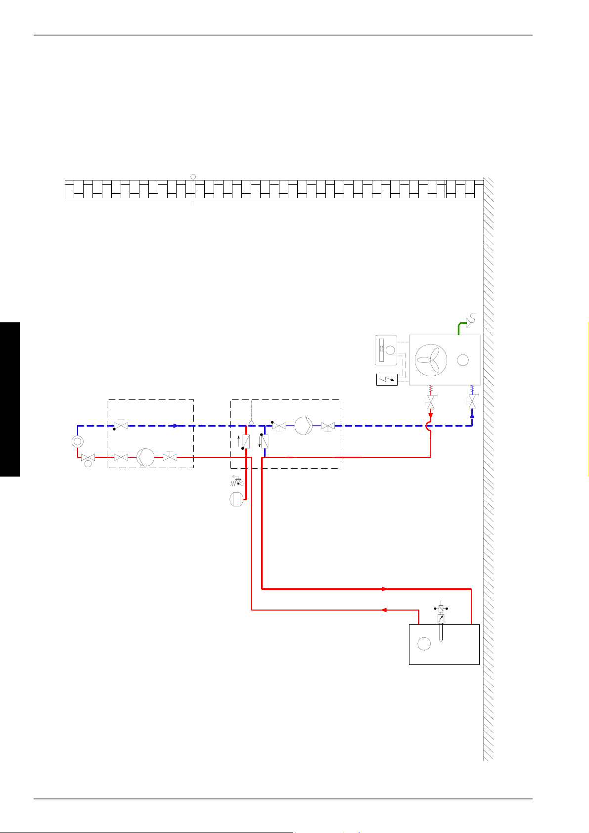
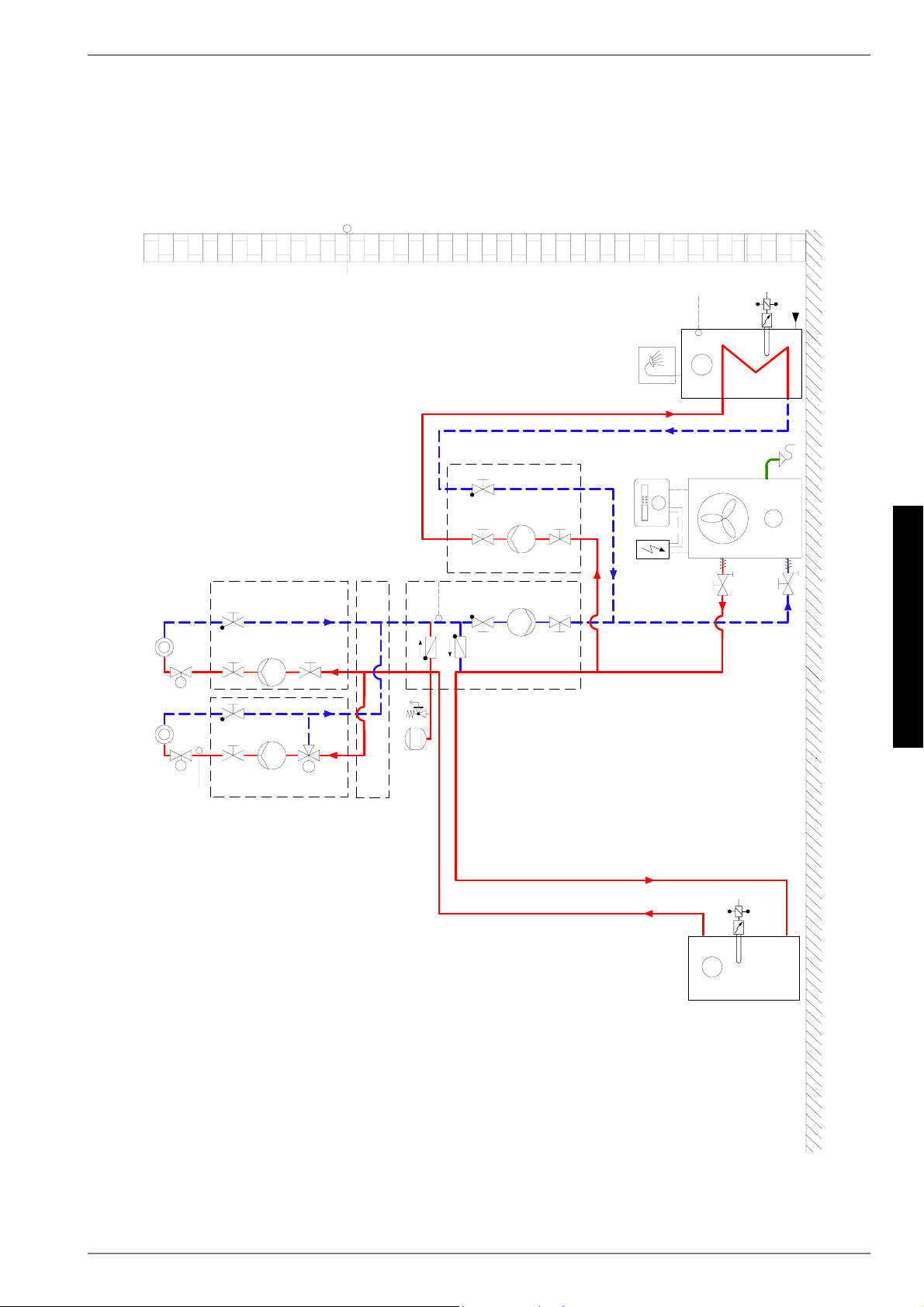
2.2Operating Principle
Surrounding air is drawn in by the ventilator and fed via the evap-
orator (heat exchanger). The evaporator cools the air, i.e. it ex-
tracts heat from it. This extracted heat is then transferred to the
working medium (refrigerant) in the evaporator.
The heat is “pumped” to a higher temperature level by increasing
its pressure with the aid of an electrically driven compressor. It is
then transferred to the heating water using the liquifier (heat ex-
changer).
Electrical energy is used to raise the temperature of the heat in
the environment to a higher level. Because the energy extracted
from the air is transferred to the heating water, this type of device
is called an air-to-water heat pump.
The air-to-water heat pump consists of the main components
evaporator, ventilator and expansion valve, as well as the low-
noise compressor, liquifier and electrical control system.
At low ambient temperatures, humidity accumulates on the evap-
orator in the form of frost reducing the transfer of heat. The evap-
orator is defrosted automatically by the heat pump as required.
Steam may be emitted from the air outlet depending on the at-
mospheric conditions.
3Scope of Delivery
3.1Basic Device
The heat pump is of compact design and is supplied complete
with the components listed below.
The refrigerant circuit is hermetically sealed. It contains the
Kyoto protocol approved refrigerant R404A with a GWP value of
3260. It is CFC-free, does not deplete ozone and is non-flamma-
ble.
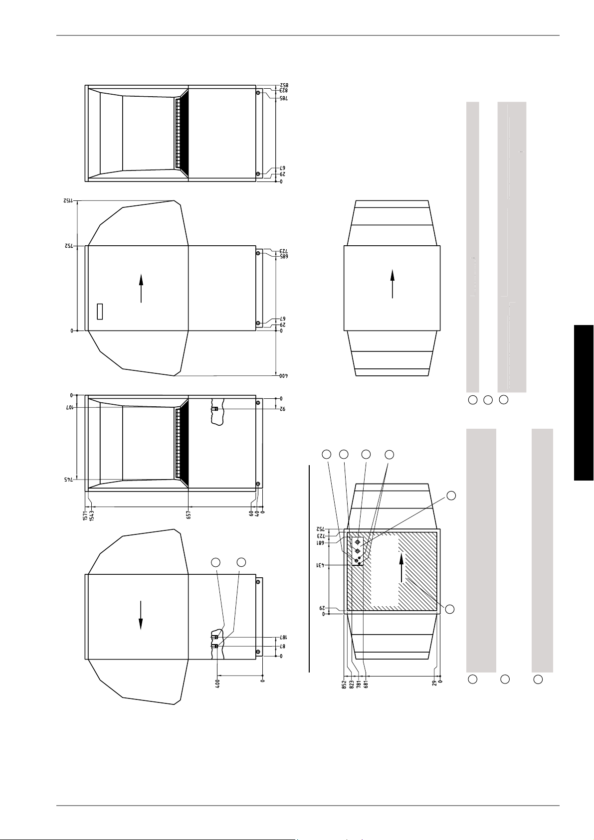
1)Evaporator
2)Check valve
3)Ventilator
4)Switch box
5)Controllers
6)Filter dryer
7)Liquifier
8)Expansion valve
9)Compressor
EN-4
English
3.2
3.2Switch Box
The switch box is located in the heat pump. It can be swung out
after removing the lower front cover and loosening the fastening
screw located in the upper right-hand corner.
The switch box contains the supply connection terminals as well
the power contactors and the soft starter unit.
The plug connector for the control line is located on the base of
the device adjacent to the cable gland in the base plate.
3.3Heat Pump Manager
Use the heat pump manager included in the scope of supply to
operate the air-to-water heat pump.
The heat pump manager is a convenient electronic regulation
and control device. It controls and monitors the entire heating
system on the basis of the external temperature, including hot
water preparation and safety systems.
The customer must install the return temperature sensor and the
external temperature sensor, which are supplied with the heat
pump manager / with these instructions together with the neces-
sary fixing accessories.
The enclosed operating instructions describe the function and
use of the heat pump manager.
4Transport
ATTENTION!
When transporting the heat pump, ensure that it is not tilted more than
45° (in any direction).
Use a wooden pallet for transporting the heat pump to the final in-
stallation location. The basic device can be transported with a lift
truck, hand truck or by means of 3/4" pipes fed through the holes
in the base plate or frame.
The heat pump and the transport pallet are joined by four transit
bolts. These must be removed.
Before using the transport holes in the frame, it is necessary to
remove the lower side panel assemblies. This is done by loosen-
ing each of the two screws at the base and then withdrawing the
panels by unhooking them from above. Rehang the panels by
gently pushing them in an upwards direction.
Be careful not to damage any components when inserting the
pipes through the frame.
At the installation location, 8 black dust caps, which are included
in the packaging of the device, must be snapped into the trans-
port holes.
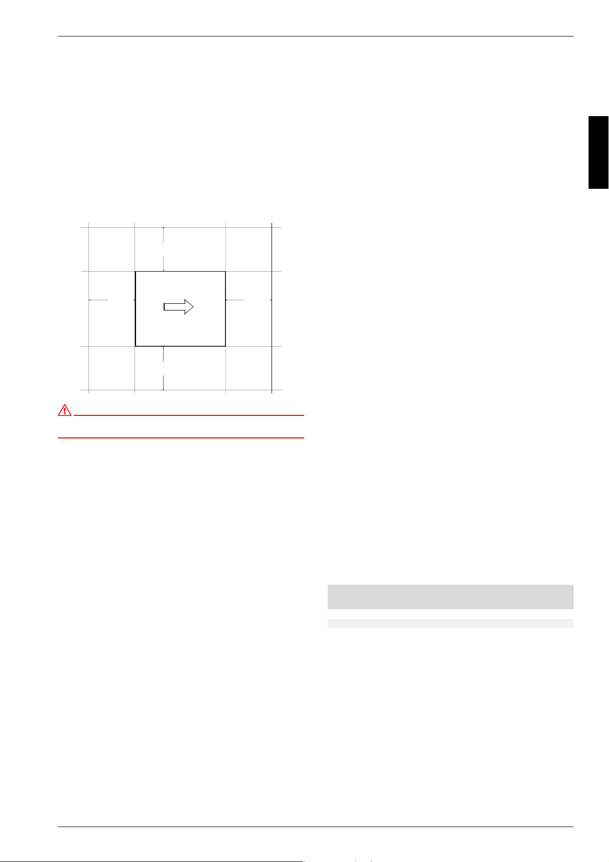
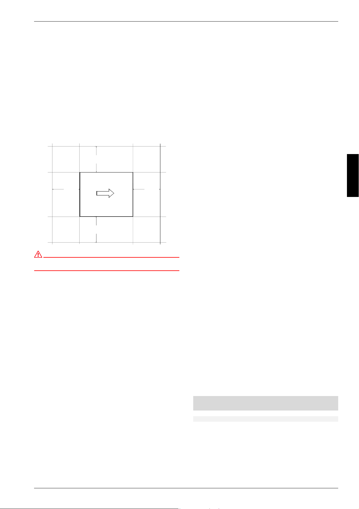
Opening the coverClosing the cover
www.dimplex.deEN-5
English
6.2
5Set-UP
5.1General Information
The device should always be installed on a permanently smooth,
even and horizontal surface. The entire frame should lie directly
on the ground to ensure a good soundproof seal and to prevent
the water-bearing components from becoming too cold. If this is
not the case, additional insulation measures may be necessary.
It must be possible to carry out maintenance work without hin-
drance. This can be ensured by maintaining a clearance of 1.2m
to any fixed walls.
ATTENTION!
Do not restrict or block the area around the air intake or outlet.
5.2Condensed Water Pipe
Condensed water that forms during operation must be drained
off frost-free. To ensure proper drainage, the heat pump must be
mounted horizontally. The condensed water pipe must have a
minimum diameter of 50mm and should be fed frost-free into a
sewer. Do not discharge the condensate directly into clearing
tanks or cesspits, as aggressive vapours or a condensed water
pipe which has not been laid in a frost-free manner could destroy
the evaporator.
6Installation
6.1General Information
The following connections need to be established on the heat
pump:
Flow and return flow of the heating system
Condensate outflow
Control line to the heat pump manager
Power supply
6.2Heating System Connection
The heating system connections on the heat pump have a 1" ex-
ternal thread. Route the connection hoses out of the device in a
downwards direction. Use a spanner to firmly grip the transitions
when connecting the heat pump.
Before connecting the heating water system to the heat pump,
the heating system must be flushed to remove any impurities,
residue from sealants, etc. Any accumulation of deposits in the
liquifier could cause the heat pump to completely break down.
For systems in which the heating water flow can be shut off via
the radiator or thermostat valves, an overflow valve must be in-
stalled in a heating bypass behind the heat pump by the cus-
tomer. This ensures a minimum heating water flow rate through
the heat pump and helps to avoid faults.
Once the heating system has been installed, it must be filled, de-
aerated and pressure-tested.
Consideration must be given to the following when filling the sys-
tem:
Untreated filling water and make-up water must be of drink-
ing water quality (colourless, clear, free from sediments)
Filling water and make-up water must be pre-filtered (pore
size max. 5µm).
Scale formation in hot water heating systems cannot be com-
pletely avoided, but in systems with flow temperatures below
60°C the problem can be disregarded.
With medium and high-temperature heat pumps, temperatures
above 60°C can be reached.
The following standard values should therefore be adhered to
concerning the filling water and make-up water (according to VDI
2035 Sheet 1):
Minimum heating water flow rate
The minimum heating water flow rate through the heat pump
must be assured in all operating states of the heating sys-
tem. This can be accomplished, for example, by installing either
a dual differential pressureless manifold or an overflow valve.
The procedure for adjusting an overflow valve is described in the
Chapter Start-Up. When the minimum flow rate is undershot
drastically, the plate steel exchanger in the refrigerating cycle
can freeze, which can lead to total loss of the heat pump.
NOTE
The use of an overflow valve is only recommended for panel heating and
a max. heating water flow of 1.3 m³/h. System faults may result if this is
not observed.
PP
P
P
Total heat
output in [kW]
Total alkaline earths
in mol/m³ and/or
mmol/l
Total
hardness in dH
up to 200≤ 2.0≤ 11.2
200 to 600≤ 1.5≤ 8.4
> 600< 0.02< 0.11
EN-6
English
6.3
Antifreeze
A method of manual drainage (see illustration) should be pro-
vided for heat pumps which are exposed to frost. The antifreeze
function of the heat pump manager is active whenever the heat
pump manager and the heat circulating pump are ready for oper-
ation. If the heat pump is taken out of service or in the event of a
power failure, the system has to be drained. The heating circuit
should be operated with a suitable antifreeze if heat pump sys-
tems are implemented in buildings where a power failure can not
be detected (holiday home).
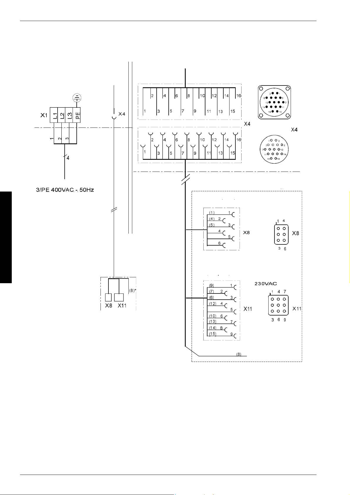
6.3Electrical Connection
A standard four-core cable is used for connecting the heat pump
to the power supply.
The cable must be provided by the customer. The conductor
cross section is selected in accordance with the power consump-
tion of the heat pump (see Appendix Device Information) and the
applicable VDE (EN) and VNB regulations.
An all-pole disconnecting device with a contact gap of at least
3mm (e.g. utility blocking contactor or power contactor) as well
as a 3-pole circuit breaker with common tripping for all external
conductors must be installed in the power supply (tripping current
in compliance with the Device Information).
Ensure that the incoming supply has a clockwise rotating field
when connecting multiphase devices.
Phase sequence: L1, L2, L3.
ATTENTION!
Ensure that there is a clockwise rotating field: Operating the compressor
in the wrong rotational direction could cause damage to the compressor.
The control voltage is supplied via the heat pump manager.
The heat pump manager has a 230 V AC-50 Hz power supply.
Connect the controller in compliance with its own operating in-
structions (16 A fuse).
The control line (not included in scope of supply) is connected to
the heat pump manager using the two rectangular plug connec-
tors. Use the plug connector located on the base of the heat
pump adjacent to the cable gland in the base plate. More de-
tailed information can be found in the operating instructions of
the heat pump manager.
For detailed information, see Circuit Diagrams in the Appendix.
7Start-UP
7.1General Information
To ensure that start-up is performed correctly, it should only be
carried out by an after-sales service technician authorised by the
manufacturer. This may be a condition for extending the guaran-
tee (see Warranty Service).
7.2Preparation
The following items need to be checked prior to start-up:
The heat pump must be fully connected, as described in
Chapter 6.
All valves that could impair the proper flow of the heating
water in the heating circuit must be open.
The air intake and air outlet paths must be clear.
The ventilator must turn in the direction indicated by the ar-
row.
The settings of the heat pump manager must be adapted to
the heating system in accordance with the controller’s oper-
ating instructions.
Ensure the condensate outflow functions.
7.3Procedure
The heat pump is started up via the heat pump manager. Adjust-
ments should be made in compliance with the instructions.
If an overflow valve is fitted to maintain the minimum heat-
ing water flow rate, the valve must be adapted to the require-
ments of the heating system. Incorrect adjustment can lead to
faulty operation and increased energy consumption. We recom-
mend carrying out the following procedure to correctly adjust the
overflow valve:
Close all of the heating circuits that may also be closed during
operation (depending on the type of heat pump usage) so that
the most unfavorable operating state - with respect to the water
flow rate - is achieved. This normally means the heating circuits
of the rooms on the south and west sides of the building. At least
one heating circuit must remain open (e.g. bathroom).
The overflow valve should be opened far enough to produce the
maximum temperature spread between the heating flow and re-
turn flow listed in the following table for the current heat source
temperature. The temperature spread should be measured as
close as possible to the heat pump. The heating element of mono
energy systems should be disconnected during start up.
Heat source
temperature
Max. temperature spread
between heating flow and return
flow
FromTo
-20°C-15°C4 K
-14°C-10°C5 K
-9°C-5°C6 K
-4°C0°C7 K
1°C5°C8 K
6°C10°C9 K
11°C15°C10 K
16°C20°C11 K
21°C25°C12 K
26°C30°C13 K
31°C35°C14 K
www.dimplex.deEN-7
English
8.3
At hot water temperatures under 7° C, start-up is not possible.
The water in the buffer tank must be heated to a minimum
of 18 °C with the second heat generator.
To ensure a problem-free start-up, the following procedure is to
be implemented:
1)Close all consumer circuits.
2)Ensure that the heat pump has the correct water flow.
3)Use the manager to select the automatic operating mode.
4)In the special functions menu, start the "Start-up" program.
5)Wait until a return temperature of at least 25 °C has been
reached.
6)Now slowly reopen the heating circuit valves in succession
so that the heating water flow is constantly raised by slightly
opening the respective heating circuit. The heating water
temperature in the buffer tank must not be allowed to drop
below 20°C during this process. This ensures that the heat
pump can be defrosted at any time.
7)When all heat circuits are fully open and a return tempera-
ture of at least 18° C is maintained, the heat pump start-up
is complete.
8Maintenance / Cleaning
8.1Maintenance
To protect the paintwork, avoid leaning or putting objects on the
device. External heat pump parts can be wiped with a damp cloth
and domestic cleaner.
ATTENTION!
Never use cleaning agents containing sand, soda, acid or chloride as
these can damage the surfaces.
To prevent faults due to sediment in the heat exchanger of the
heat pump, ensure that the heat exchanger in the heating system
can not be contaminated. In the event that operating malfunc-
tions due to contamination still occur, the system should be
cleaned as described below.
8.2Cleaning the Heating System
The ingress of oxygen into the heating water circuit may result in
the formation of oxidation products (rust), particularly if steel
components are used. These products enter the heating system
via the valves, the circulating pumps and/or plastic pipes. It is
therefore essential - in particular with respect to the piping of un-
derfloor heating systems - that only diffusion-proof materials are
used.
ATTENTION!
We recommend the installation of a suitable corrosion protection system
to prevent the formation of deposits (e.g. rust) in the condenser of the
heat pump.
Residue from lubricants and sealants may also contaminate the
heating water.
In the case of severe contamination leading to a reduction in the
performance of the liquifier in the heat pump, the system must be
cleaned by a heating technician.
According to today's state of knowledge, we recommend using a
5 % phosphoric acid solution for cleaning purposes. However, if
cleaning needs to be performed more frequently, a 5 % formic
acid solution should be used.
In either case, the cleaning fluid should be at room temperature.
We recommend flushing the heat exchanger in the direction op-
posite to the normal flow direction.
To prevent acidic cleaning agents from entering the heating sys-
tem circuit, we recommend connecting the flushing device di-
rectly to the flow and return flow of the liquifier of the heat pump.
It is important that the system be thoroughly flushed using appro-
priate neutralising agents to prevent any damage from being
caused by cleaning agent residue remaining in the system.
Acids must be used with great care and all relevant regulations of
the employers' liability insurance associations must be adhered
to.
If in doubt, contact the manufacturer of the chemicals!
8.3Cleaning the Air System
Evaporator, ventilator and condensate outflow should be cleaned
of contamination (leaves, twigs, etc.) before the heating period.
Do this by opening the front of the heat pump. The bottom should
be opened first followed by the top.
ATTENTION!
Before opening the device, ensure that all circuits are isolated from the
power supply.
Remove and rehang the side panel assemblies as described in
Chapter 4.
To prevent the evaporator and the condensate tray from being
damaged, do not use hard or sharp objects for cleaning.
Under extreme weather conditions (e.g. snow drifts), ice may
form on the air intake and exhaust air outlet grids. If this happens,
the ice must be removed in the vicinity of the air intake and ex-
haust air outlet grids to ensure that the minimum air flow rate is
maintained.
EN-8
English
9
9Faults / Trouble-
Shooting
This heat pump is a quality product and is designed for trouble-
free and maintenance-free operation. In the event that a fault
should occur, it will be shown on the heat pump manager display.
Simply consult the Faults and Trouble-shooting page in the oper-
ating instructions of the heat pump manager. If you cannot cor-
rect the fault yourself, please contact your after-sales service
technician.
ATTENTION!
Any work on the heat pump may only be performed by authorised and
qualified after-sales service technicians.
10Decommissioning/
Disposal
Before removing the heat pump, disconnect it from the power
source and close all valves. Observe all environmentally-relevant
requirements regarding the recovery, recycling and disposal of
materials and components in accordance with all applicable
standards. Particular attention should be paid to the proper dis-
posal of refrigerants and refrigeration oils.
www.dimplex.deEN-9
English
11
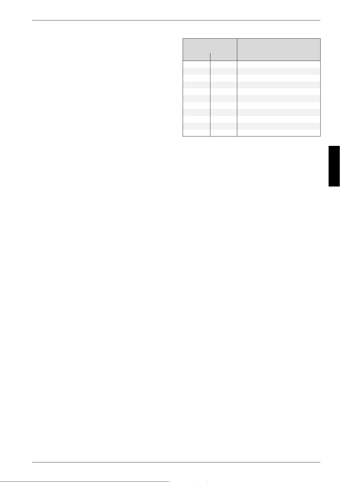
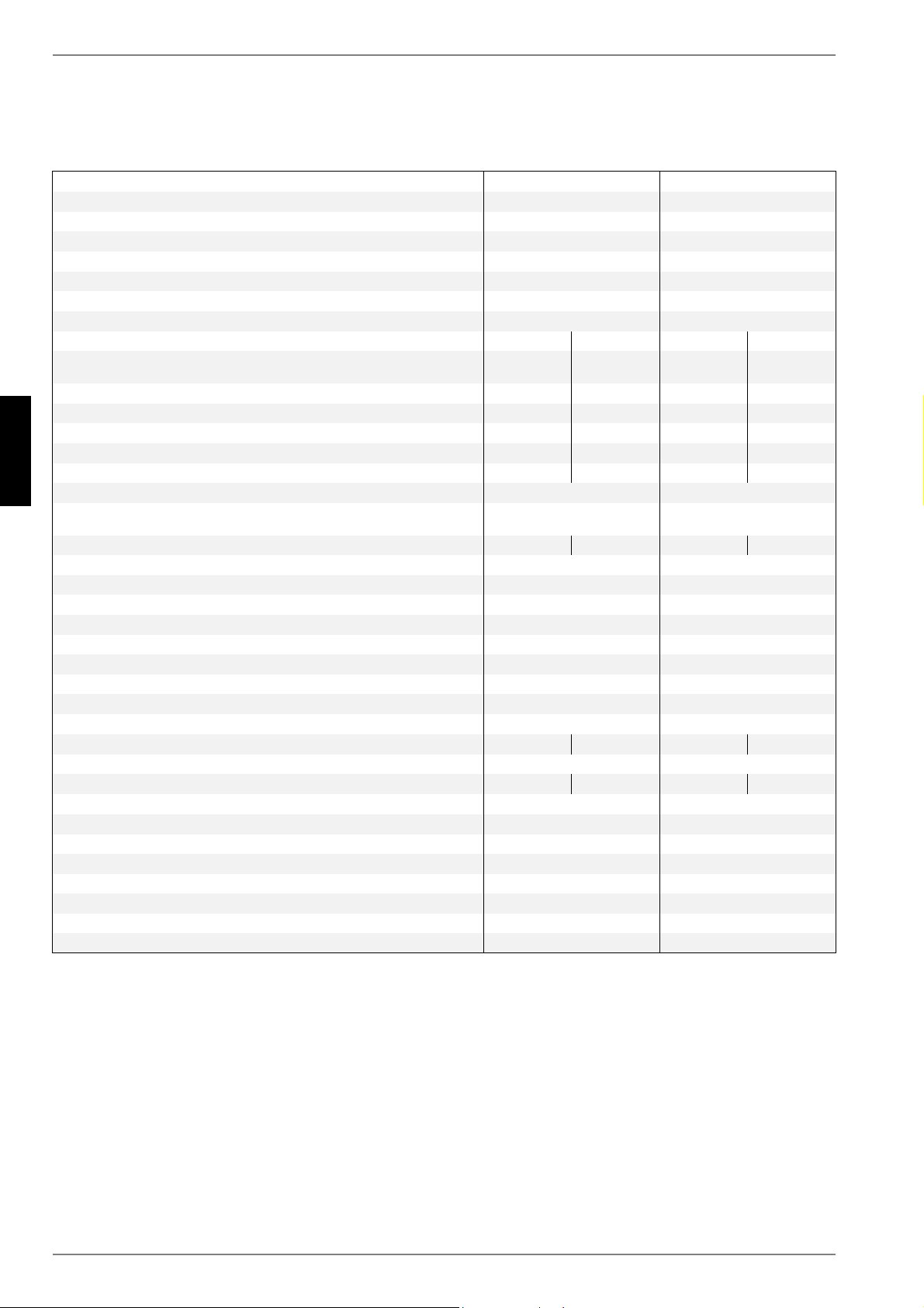
11Device Information
1Type and order code LA11ASLA16AS
2Design
2.1Degree of protection according to EN 60 529 for compact devices
and heating components IP 24 IP 24
2.2Installation locationOutdoorsOutdoors
3Performance data
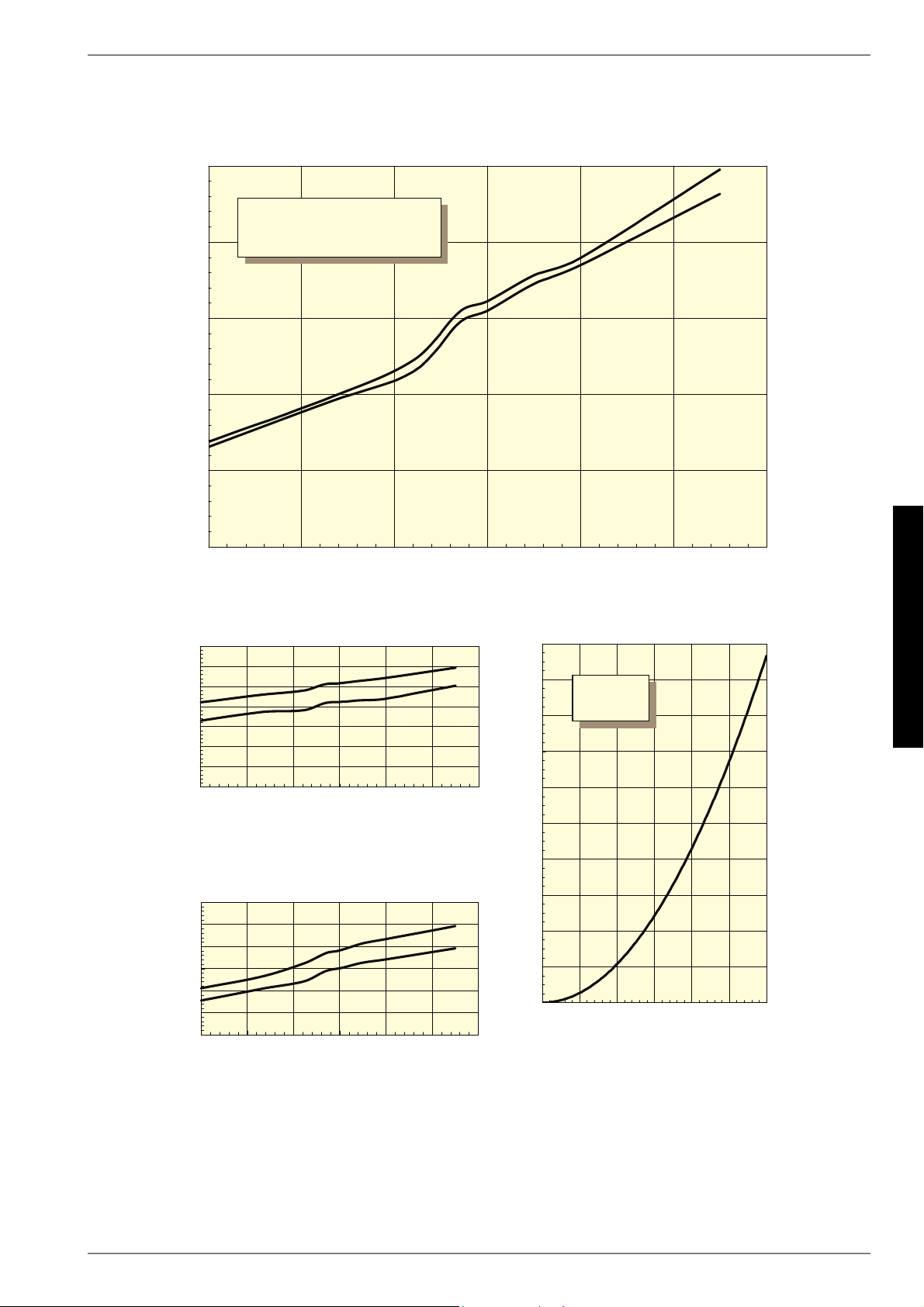
3.1Operating temperature limits:
Heating water flow/return flow 1°C /°C
1.See operating limits diagram
Up to 58 / above 18Up to 58 / above 18
Air°C-25 bis +35-25 bis +35
3.2Temperature spread of heating water (flow/return flow) at A7 / W359.75.09.55.0
3.3Heat output / COP at A-7 / W35 2kW / ---
2.This data indicates the size and capacity of the system according to EN 255 and EN 14511. For an analysis of the economic and energy efficiency of the system, other parameters,
such as, in particular, the defrosting capacity, the bivalence point and regulation, should also be taken into consideration. The specified values, e.g. A2 / W35, have the following
meaning: 2°C external air temperature and 35°C heating water flow temperature.
3.1Appareil de base...................................................................................................................................FR-3
7.3Procédures à suivre..............................................................................................................................FR-7
8.2Nettoyage côté chauffage.....................................................................................................................FR-8
8.3Nettoyage côté air.................................................................................................................................FR-8
9Défaillances/recherche de pannes...........................................................................................FR-9
10Mise hors service / mise au rebut.............................................................................................FR-9
11Informations sur les appareils................................................................................................FR-10
nécessaires. Les travaux de maintenance doivent pouvoir être
effectués sans problème. C’est tout à fait possible si on observe
un écartement de 1,2m entre l’appareil et les murs.
ATTENTION !
Les canaux d’aspiration et d’évacuation d'air ne doivent être ni rétrécis,
ni obturés.
5.2Ecoulement des condensats
Les condensats se formant en cours de fonctionnement doivent
être évacués sans risque de gel. Pour garantir un écoulement ir-
réprochable, la pompe à chaleur doit être placée à l’horizontale.
Le tuyau d'évacuation des condensats doit avoir un diamètre
d'au moins 50mm et déboucher à l'abri du gel dans la canalisa-
tion des eaux usées. Ne pas diriger directement l'eau de conden-
sation vers des bassins de décantation ou des fosses Les va-
peurs corrosives ainsi qu'une conduite d'écoulement des
condensats non protégée contre le gel peuvent causer la des-
truction de l'évaporateur.
6Installation
6.1Remarques d’ordre général
Les raccordements suivants doivent être réalisés sur la pompe à
chaleur :
Circuits départ et retour de l’installation de chauffage
Ecoulement des condensats
Câble de commande vers gestionnaire de pompe à chaleur
Alimentation électrique
6.2Branchement côté installation
de chauffage
Les raccordements côté chauffage à la pompe à chaleur sont
pourvus de filetages extérieurs 1". Les flexibles à raccorder sont
sortis de l'appareil par le bas. Pour raccorder la pompe à chaleur,
il faudra contre-bloquer au niveau des traversées à l’aide d’une
clé.
Avant de procéder au raccordement de la pompe à chaleur côté
eau de chauffage, l’installation de chauffage doit être rincée pour
éliminer d’éventuelles impuretés et les restes éventuels des ma-
tériaux d’étanchéité ou autres. Une accumulation de dépôts di-
vers dans le condenseur est susceptible d'entraîner une dé-
faillance totale de la pompe à chaleur. Pour des installations
avec écoulement d’eau de chauffage muni d’arrêt, conditionné
par les vannes à thermostat ou de radiateur, une vanne de trop-
plein doit être montée derrière la pompe à chaleur dans une dé-
rivation du chauffage. Ceci garantit un débit d'eau de chauffage
minimum via la pompe à chaleur et empêche les dysfonctionne-
ments.
Une fois le montage côté chauffage terminé, l’installation de
chauffage devra être remplie, purgée et éprouvée à la pression.
Respecter les consignes suivantes lors du remplissage de
l'installation:
l'eau de remplissage et l'eau additionnelle non traitées doi-
vent être de même qualité que l'eau potable
(incolore, claire et sans dépôt)
l'eau de remplissage et l'eau additionnelle doivent être pré-
filtrées (écartement max. des pores 5µm).
Il n'est pas possible d'empêcher totalement la formation de cal-
caire dans les installations de chauffage à eau chaude. Sa quan-
tité est cependant négligeable pour les installations ayant des
températures aller inférieures à 60°C.
Les pompes à chaleur moyenne et haute température peuvent
également atteindre des températures supérieures à 60°C.
Les valeurs indicatives suivantes pour l'eau additionnelle et l'eau
de remplissage doivent donc être respectées selon VDI2035
feuillet 1:
PP
P
P
Puissance calorifique
totale en [kW]
Somme des alcalinoter-
reux en mol/m³
ou mmol/l
Dureté
totale en dH
jusqu'à 200≤ 2,0≤ 11,2
de 200 à 600≤ 1,5≤ 8,4
> 600< 0,02< 0,11
FR-6
Français
6.3
Débit d'eau de chauffage minimum
Quel que soit l'état de fonctionnement de l'installation de chauf-
fage, un débit d'eau de chauffage minimum doit être garanti dans
la pompe à chaleur. Cela peut par ex. être obtenu par l'installa-
tion d'un distributeur double sans pression différentielle ou d'une
soupape différentielle. Vous trouverez des explications quant au
réglage d'une vanne de tropplein dans le chapitre " Mise en ser-
vice ". Un dépassement drastique de la limite inférieure du débit
minimum peut entraîner la destruction totale de la pompe à cha-
leur en cas de gel de l'échangeur thermique à plaques du circuit
réfrigérant.
REMARQUE
L'utilisation d'une soupape différentielle est uniquement
recommandée pour les chauffages par surfaces et pour un débit
d'eau de chauffage max. de 1,3 m³/h. Le non-respect de cette remarque
peut entraîner des défauts de fonctionnement de l'installation.
Protection antigel
Dans le cas de pompes à chaleur exposées au gel, une vidange
manuelle du circuit de chauffage devrait être prévue. La fonction
de protection antigel du gestionnaire de pompe à chaleur fonc-
tionne dès que le gestionnaire de pompe à chaleur et les circula-
teurs de chauffage sont opérationnels. L’installation doit être vi-
dangée en cas de mise hors service de la pompe à chaleur ou
coupure de courant. Pour les installations de pompe à chaleur
qui pourraient être victimes de pannes de courant non décela-
bles (maison de vacances), le circuit de chauffage doit fonction-
ner avec une protection anti-gel appropriée.
6.3Branchements électriques
Le raccordement en puissance de la pompe à chaleur s’effectue
via un câble à 4 fils normal, vendu dans le commerce.
Le câble doit être mis à disposition par le client et la section du
conducteur doit être choisie en fonction de la consommation de
puissance de la pompe à chaleur (voir annexe informations sur
les appareils) et selon les prescriptions VDE, EN et CEI afféren-
tes.
Prévoir pour l’alimentation de puissance un débranchement de
tous les pôles avec au moins 3mm d’écartement d’ouverture de
contact (par ex. sur le disjoncteur général ou sur le contacteur de
puissance), ainsi qu’un coupe-circuit automatique tripolaire, avec
déclenchement simultané de tous les conducteurs extérieurs (in-
tensité de déclenchement conforme aux informations sur les ap-
pareils).
Lors du raccordement, garantir la rotation à droite du champ ma-
gnétique de l’alimentation de charge.
Ordre des phases : L1, L2, L3. L1, L2, L3.
ATTENTION !
Respecter la rotation à droite du champ magnétique : Le compresseur
peut être endommagé si le sens de rotation est le mauvais.
La tension de commande est amenée via le gestionnaire de
pompe à chaleur.
L’alimentation en courant du gestionnaire de pompe à chaleur
avec 230 VAC-50Hz s’effectue conformément à ses propres
instructions de service (protection par fusibles 16A).
La ligne de commande (n’est pas intégrée à la fourniture) est re-
liée à l’aide des deux connecteurs rectangulaires au gestionnaire
de pompe à chaleur. Dans la pompe à chaleur, utiliser le
connecteur se trouvant directement sur le socle de l’appareil à
proximité immédiate du trou de passage pour câbles à travers le
sol. Des instructions plus précises se trouvent dans les instruc-
tions d'utilisation du gestionnaire de pompe à chaleur.
Pour des informations plus détaillées, cf. schémas électriques en
annexe.
www.dimplex.deFR-7
Français
7.3
7Mise en service
7.1Remarques d’ordre général
Pour garantir une mise en service en règle, cette dernière doit
être effectuée par un service après-vente agréé par le construc-
teur. Ceci permet de prolonger la garantie sous certaines condi-
tions (cf. Garantie).
7.2Préparation
Avant la mise en service, il est impératif de procéder aux vérifica-
tions suivantes :
tous les raccordements de la pompe à chaleur doivent être
réalisés comme décrit au chapitre 6.
dans les circuits de chauffage et d'eau glycolée, toutes les
vannes susceptibles de perturber l'écoulement doivent être
ouvertes.
les voies d’aspiration et d'évacuation de l’air doivent être dé-
gagées.
le sens de rotation du ventilateur doit correspondre à la di-
rection de la flèche.
les réglages du gestionnaire de pompe à chaleur doivent
être accordés à l'installation de chauffage conformément à
ses instructions de service.
l’écoulement des condensats doit être assuré.
7.3Procédures à suivre
La mise en service de la pompe à chaleur s'effectue via le ges-
tionnaire de pompe à chaleur. Les réglages doivent être effec-
tués selon les instructions de celui-ci.
Si le débit minimal en eau de chauffage est assuré par une
vanne de trop-plein, il faut adapter celle-ci à l'installation de
chauffage. Un mauvais réglage pourrait conduire à divers mes-
sages d'erreur et à une augmentation du besoin en énergie élec-
trique. Pour régler la vanne de trop-plein correctement, nous
vous conseillons de procéder de la manière suivante.
Fermez tous les circuits de chauffage pouvant l'être en phase de
fonctionnement, selon l'utilisation qu'il en est faite; ceci ayant
pour but d'obtenir le débit d'eau le plus défavorable. En règle gé-
néral, ce sont les circuits de chauffage des locaux donnant sur le
côté sud et ouest. Au moins un des circuits de chauffage doit res-
ter ouvert (par ex. salle de bains).
La vanne de trop-plein est à ouvrir au maximum de telle sorte
que, pour la température actuelle des sources d'énergie, l'étale-
ment maximal de température, indiqué dans le tableau, entre cir-
cuit départ et retour du chauffage, soit obtenu. Il faut mesurer
l'étalement de température le plus près possible de la pompe à
chaleur. Dans des installations mono-énergétiques, désactiver
la cartouche chauffante pendant la mise en service.
Il n'est pas possible de procéder à une mise en service pour des
températures d'eau de chauffage inférieures à 7 °C. L'eau du ré-
servoir tampon doit être chauffée par le 2ème générateur de cha-
leur à une température de 18 °C minimum.
Suivre ensuite la procédure indiquée ci-après pour procéder à
une mise en service sans défauts :
1)Fermer tous les circuits consommateurs.
2)Garantir le débit d'eau de la pompe à chaleur.
3)Sélectionner le mode " Automatique " sur le gestionnaire.
4)Lancer le programme " Mise en service " dans le menu
Fonctions spéciales.
5)Attendre jusqu'à atteinte d'une température retour de 25 °C
minimum.
6)Rouvrir ensuite lentement l'un après l'autre les clapets des
circuits de chauffage de telle sorte que le débit d'eau
de chauffage augmente de façon régulière par la légère
ouverture du circuit de chauffage concerné. La tempé-
rature de l'eau de chauffage dans le réservoir tampon ne
doit pas descendre en dessous de 20 °C pour permettre à
tout moment un dégivrage de la pompe à chaleur.
7)La mise en service de la pompe à chaleur est terminée lors-
que tous les circuits de chauffage sont complètement
ouverts et qu'une température de retour de 18 °C minimum
est maintenue.
Température
de départ
Différence de température max.
entre circuits départ et retour du
chauffage
deà
-20°C-15°C4 K
-14°C-10°C5 K
-9°C-5°C6 K
-4°C0°C7 K
1°C5°C8 K
6°C10°C9 K
11°C15°C10 K
16°C20°C11 K
21°C25°C12 K
26°C30°C13 K
31°C35°C14 K
FR-8
Français
8
8Nettoyage / entretien
8.1Entretien
Il faut éviter d’appuyer ou de déposer des objets sur l’appareil
afin de protéger la laque. Les parties extérieures de la pompe à
chaleur peuvent être essuyées avec un linge humide et des pro-
duits à nettoyer usuels vendus dans le commerce.
ATTENTION !
N’utilisez jamais de produits d’entretien contenant du sable, de la soude,
de l’acide ou du chlore, car ils attaquent les surfaces.
Pour éviter des dysfonctionnements dus à des dépôts dans
l’échangeur thermique de la pompe à chaleur, il faut veiller à ce
que l'échangeur de chaleur dans l’installation de chauffage ne
puisse pas s’encrasser. Si des dysfonctionnements dus à des
impuretés devaient se produire malgré cette mesure, l'installa-
tion devra être nettoyée comme indiqué ci-après.
8.2Nettoyage côté chauffage
L’oxygène est susceptible d’entraîner la formation de produits
d’oxydation (rouille) dans l’eau de chauffage, notamment lorsque
des composants en acier sont utilisés. Ces produits d’oxydation
gagnent le système de chauffage par les vannes, les circulateurs
ou les tuyaux en matière plastique. C’est pourquoi il faut veiller à
ce que l’installation reste étanche à la diffusion, notamment en
ce qui concerne les tuyaux du chauffage au sol.
ATTENTION !
Il est recommandé de faire appel à un système approprié de protection
contre la corrosion pour éviter les dépôts (rouille par ex.) dans le
condensateur de la pompe à chaleur.
Il est également possible que l’eau de chauffage soit souillée par
des restes de graisse et d’agents d’étanchéification.
Si en raison d’impuretés la puissance du condenseur de la
pompe à chaleur se trouve réduite, l’installation devra être net-
toyée par l’installateur.
Dans l'état actuel des connaissances, nous conseillons de pro-
céder au nettoyage avec de l’acide phosphorique à 5% ou, si le
nettoyage est plus fréquent, avec de l’acide formique à 5%.
Dans les deux cas, le liquide de nettoyage doit être à la tempéra-
ture ambiante. Il est recommandé de nettoyer l'échangeur de
chaleur dans le sens contraire au sens normal du débit.
Pour éviter l’infiltration de nettoyant contenant de l’acide dans le
circuit de l’installation de chauffage, nous vous recommandons
de raccorder l’appareil de nettoyage directement sur le départ et
le retour du condenseur de la pompe à chaleur.
Il faut ensuite soigneusement rincer à l’aide de produits neutrali-
sants adéquats, afin d’éviter tous dommages provoqués par
d’éventuels restes de produits de nettoyage dans le système.
Les acides doivent être utilisés avec précaution et les prescrip-
tions des caisses de prévoyance des accidents doivent être res-
pectées.
En cas de doute, prendre contact avec les fabricants des pro-
duits chimiques !
8.3Nettoyage côté air
L’évaporateur, l’aérateur et l’écoulement des condensats doivent
être nettoyés de leurs impuretés (feuilles, branches etc.) avant la
période de chauffage. Ouvrir la pompe à chaleur sur le côté gau-
che et en façade, d’abord en bas puis en haut.
ATTENTION !
Avant d’ouvrir l’appareil, assurez-vous que tous les circuits électriques
sont bien hors tension.
Le démontage et l’accrochage des panneaux de façade s’effec-
tue comme décrit au chapitre 4.
L’utilisation d’objets pointus et durs est à éviter lors du nettoyage
afin d´empêcher toute détérioration de l’évaporateur et de la
cuve de condensats.
Lors de conditions atmosphériques extrêmes (amas de neiges
par ex.), de la glace peut se former sur les grilles d’aspiration et
d’évacuation. Il faut libérer dans ce cas le domaine d’aspiration
et d’évacuation de la glace et de la neige afin de pouvoir garantir
le débit d’air minimum.
www.dimplex.deFR-9
Français
10
9Défaillances/recherche
de pannes
Cette pompe à chaleur est un produit de qualité et elle devrait
fonctionner sans défauts. Si un dysfonctionnement devrait quand
même survenir, celui-ci sera affiché sur l’écran du gestionnaire
de pompe à chaleur. Référez-vous pour cela à la page des dys-
fonctionnements et de recherche de panne dans les instructions
du gestionnaire de pompe à chaleur. Si vous n'êtes pas en me-
sure de remédier vous-même au dysfonctionnement, veuillez
vous adresser au service après-vente compétent.
ATTENTION !
Les travaux sur la pompe à chaleur doivent être effectués uniquement par
des techniciens qualifiés et agréés.
10Mise hors service / mise
au rebut
Avant de démonter la pompe à chaleur, il faut mettre la machine
hors tension et fermer toutes les vannes. Il faut se conformer aux
exigences relatives à l'environnement quant à la récupération, la
réutilisation et l’élimination de consommables et de composants
en accord avec les normes en vigueur. Une attention toute parti-
culière doit être prêtée à l’évacuation du réfrigérant et de l’huile
de la machine frigorifique, qui doit s’effectuer selon les règles de
l’art.
FR-10
Français
11
11Informations sur les
appareils
1Désignation technique et commercialeLA11ASLA16AS
2Forme
2.1Type de protection selon EN 60 529 pour app. compact ou élt. de chauffe IP 24 IP 24
2.2Emplacementen extérieuren extérieur
3Indications de puissance
3.1Température - limites d’exploitation :
Départ/retour eau de chauffage 1°C /°C
1.voir diagramme des limites d’utilisation
jusqu’à 58 / à p. de 18jusqu’à 58 / à p. de 18
Air°Centre -25 et +35entre -25 et +35
3.2Plage de température eau de chauffage pour A7 / W359,75,09,55,0
3.3Capacité thermique /
coef. de puissance pour A-7 / W35 2 kW / ---
2.Ces indications caractérisent la taille et le rendement de l’installation selon EN255 et EN14511. D’autres valeurs d’influence, notamment le comportement au dégivrage, le point
de bivalence et la régulation sont à prendre en compte pour des considérations économiques et énergétiques. Ici, A2 / W35 signifie par ex. : température extérieure 2°C et tem-
Gebruikershandleiding.com neemt misbruik van zijn services uitermate serieus. U kunt hieronder aangeven waarom deze vraag ongepast is. Wij controleren de vraag en zonodig wordt deze verwijderd.
Product:
Spelregels forum
Om tot zinvolle vragen te komen hanteren wij de volgende spelregels:
lees eerst de handleiding door;
controleer of uw vraag al eerder door iemand anders is gesteld;
probeer uw vraag zo duidelijk mogelijk te stellen;
heeft u een probleem en al geprobeerd om dit op te lossen, vermeld dit erbij aub;
heeft u een oplossing gekregen van een bezoeker dan horen wij dat graag in dit forum;
wilt u een reactie geven op een vraag of antwoord, gebruik dan niet dit formulier maar klik op de knop 'reageer op deze vraag';
uw vraag wordt direct op de website gezet; vermijd daarom persoonlijke gegevens in te vullen;
Belangrijk! Als er een antwoord wordt gegeven op uw vraag, dan is het voor de gever van het antwoord nuttig om te weten als u er wel (of niet) mee geholpen bent! Wij vragen u dus ook te reageren op een antwoord.
Belangrijk! Antwoorden worden ook per e-mail naar abonnees gestuurd. Laat uw emailadres achter op deze site, zodat u op de hoogte blijft. U krijgt dan ook andere vragen en antwoorden te zien.
Abonneren
Abonneer u voor het ontvangen van emails voor uw Dimplex LA 16AS bij:
nieuwe vragen en antwoorden
nieuwe handleidingen
U ontvangt een email met instructies om u voor één of beide opties in te schrijven.
Ontvang uw handleiding per email
Vul uw emailadres in en ontvang de handleiding van Dimplex LA 16AS in de taal/talen: Duits, Engels, Frans als bijlage per email.
De handleiding is 1.83 mb groot.
U ontvangt de handleiding per email binnen enkele minuten. Als u geen email heeft ontvangen, dan heeft u waarschijnlijk een verkeerd emailadres ingevuld of is uw mailbox te vol. Daarnaast kan het zijn dat uw internetprovider een maximum heeft aan de grootte per email. Omdat hier een handleiding wordt meegestuurd, kan het voorkomen dat de email groter is dan toegestaan bij uw provider.
Uw handleiding is per email verstuurd. Controleer uw email
Als u niet binnen een kwartier uw email met handleiding ontvangen heeft, kan het zijn dat u een verkeerd emailadres heeft ingevuld of dat uw emailprovider een maximum grootte per email heeft ingesteld die kleiner is dan de grootte van de handleiding.
Er is een email naar u verstuurd om uw inschrijving definitief te maken.
Controleer uw email en volg de aanwijzingen op om uw inschrijving definitief te maken
U heeft geen emailadres opgegeven
Als u de handleiding per email wilt ontvangen, vul dan een geldig emailadres in.
Uw vraag is op deze pagina toegevoegd
Wilt u een email ontvangen bij een antwoord en/of nieuwe vragen? Vul dan hier uw emailadres in.