584374
1
Verklein
Vergroot
Pagina terug
1/72
Pagina verder
AV SURROUND RECEIVER
AVR-4802
OPERATING INSTRUCTIONS
·
))
AVR-4802
PRECISION AUDIO COMPONENT / AV SURROUND RECEIVER
MASTER VOLUME
INPUT SELECTOR
ON/STANDBY
THX CINEMA
HOME
PURE
DIRECT
SENSOR
REMOTE
ON/STANDBY
INPUT
SIGNAL
PCM
AUTO
DTS
DIRECT
PURE
DIGITAL
SURROUND SPEAKER
A
B
SURROUND BACK CH
OUTPUT
DETECT
SIGNAL
ES DSCRT DVD
VOLUME LEVEL
DIGITAL
2
We greatly appreciate your purchase of the AVR-4802.
2
To be sure you take maximum advantage of all the features the AVR-4802 has to offer, read these instructions
carefully and use the set properly. Be sure to keep this manual for future reference should any questions or
problems arise.
“SERIAL NO.
PLEASE RECORD UNIT SERIAL NUMBER ATTACHED TO THE REAR OF THE
CABINET FOR FUTURE REFERENCE”
2
2 SAFETY PRECAUTIONS
2 NOTE ON USE / OBSERVATIONS RELATIVES A L’UTILISATION
Avoid high temperatures.
Allow for sufficient heat dispersion when
installed on a rack.
Eviter des températures élevées.
Tenir compte d’une dispersion de chaleur
suffisante lors de l’installation sur une étagère.
Handle the power cord carefully.
Hold the plug when unplugging the cord.
• Manipuler le cordon d’alimentation avec
précaution.
Tenir la prise lors du débranchement du
cordon.
Keep the set free from moisture, water, and
dust.
Protéger l’appareil contre l’humidité, l’eau et la
poussière.
Unplug the power cord when not using the set
for long periods of time.
Débrancher le cordon d’alimentation lorsque
l’appareil n’est pas utilisé pendant de longues
périodes.
* (For sets with ventilation holes)
Do not obstruct the ventilation holes.
Ne pas obstruer les trous d’aération.
Do not let foreign objects in the set.
Ne pas laisser des objets étrangers dans
l’appareil.
Do not let insecticides, benzene, and thinner
come in contact with the set.
Ne pas mettre en contact des insecticides, du
benzène et un diluant avec l’appareil.
Never disassemble or modify the set in any
way.
Ne jamais démonter ou modifier l’appareil
d’une manière ou d’une autre.
CAUTION
RISK OF ELECTRIC SHOCK
DO NOT OPEN
CAUTION: TO REDUCE THE RISK OF ELECTRIC SHOCK,
DO NOT REMOVE COVER (OR BACK). NO
USER-SERVICEABLE PARTS INSIDE. REFER
SERVICING TO QUALIFIED SERVICE
PERSONNEL.
The lightning flash with arrowhead symbol, within an
equilateral triangle, is intended to alert the user to the
presence of uninsulated “dangerous voltage” within the
product’s enclosure that may be of sufficient magnitude to
constitute a risk of electric shock to persons.
The exclamation point within an equilateral triangle is intended
to alert the user to the presence of important operating and
maintenance (servicing) instructions in the literature
accompanying the appliance.
WARNING:
TO REDUCE THE RISK OF FIRE OR ELECTRIC
SHOCK, DO NOT EXPOSE THIS APPLIANCE
TO RAIN OR MOISTURE.
CAUTION
TO PREVENT ELECTRIC SHOCK, MATCH WIDE BLADE OF PLUG
TO WIDE SLOT, FULLY INSERT.
ATTENTION
POUR ÉVITER LES CHOCS ÉLECTRIQUES, INTERODUIRE LA
LAME LA PLUS LARGE DE LA FICHE DANS LA BORNE
CORRESPONDANTE DE LA PRISE ET POUSSER JUSQU’ AU
FOND.
This device complies with Part 15 of the FCC Rules. Operation is subject to
the following two conditions: (1) This device may not cause harmful
interference, and (2) this device must accept any interference received,
including interference that may cause undesired operation.
This Class B digital apparatus meets all requirements of the Canadian
Interference-Causing Equipment Regulations.
Cet appareil numérique de la classe B respecte toutes les exigences du
Règlement sur le matériel brouilleur du Canada.
3
SAFETY INSTRUCTIONS
1. Read Instructions – All the safety and operating
instructions should be read before the appliance is
operated.
2. Retain Instructions – The safety and operating instructions
should be retained for future reference.
3. Heed Warnings – All warnings on the appliance and in the
operating instructions should be adhered to.
4. Follow Instructions – All operating and use instructions
should be followed.
5. Water and Moisture – The appliance should not be used
near water – for example, near a bathtub, washbowl,
kitchen sink, laundry tub, in a wet basement, or near a
swimming pool, and the like.
6. Carts and Stands – The appliance should be used only with
a cart or stand that is recommended by the manufacturer.
6A. An appliance and cart
combination should be
moved with care.
Quick stops, excessive
force, and uneven
surfaces may cause
the appliance and cart
combination to overturn.
7. Wall or Ceiling Mounting – The appliance should be
mounted to a wall or ceiling only as recommended by the
manufacturer.
8. Ventilation – The appliance should be situated so that its
location or position does not interfere with its proper
ventilation. For example, the appliance should not be
situated on a bed, sofa, rug, or similar surface that may
block the ventilation openings; or, placed in a built-in
installation, such as a bookcase or cabinet that may impede
the flow of air through the ventilation openings.
9. Heat – The appliance should be situated away from heat
sources such as radiators, heat registers, stoves, or other
appliances (including amplifiers) that produce heat.
10. Power Sources – The appliance should be connected to a
power supply only of the type described in the operating
instructions or as marked on the appliance.
11. Grounding or Polarization – Precautions should be taken so
that the grounding or polarization means of an appliance is
not defeated.
12. Power-Cord Protection – Power-supply cords should be
routed so that they are not likely to be walked on or
pinched by items placed upon or against them, paying
particular attention to cords at plugs, convenience
receptacles, and the point where they exit from the
appliance.
14. Cleaning – The appliance should be cleaned only as
recommended by the manufacturer.
15. Power Lines – An outdoor antenna should be located away
from power lines.
16. Outdoor Antenna Grounding – If an outside antenna is
connected to the receiver, be sure the antenna system is
grounded so as to provide some protection against voltage
surges and built-up static charges. Article 810 of the
National Electrical Code, ANSI/NFPA 70, provides
information with regard to proper grounding of the mast
and supporting structure, grounding of the lead-in wire to
an antenna-discharge unit, size of grounding conductors,
location of antenna-discharge unit, connection to grounding
electrodes, and requirements for the grounding electrode.
See Figure A.
17. Nonuse Periods – The power cord of the appliance should
be unplugged from the outlet when left unused for a long
period of time.
18. Object and Liquid Entry – Care should be taken so that
objects do not fall and liquids are not spilled into the
enclosure through openings.
19. Damage Requiring Service – The appliance should be
serviced by qualified service personnel when:
A. The power-supply cord or the plug has been damaged;
or
B. Objects have fallen, or liquid has been spilled into the
appliance; or
C. The appliance has been exposed to rain; or
D. The appliance does not appear to operate normally or
exhibits a marked change in performance; or
E. The appliance has been dropped, or the enclosure
damaged.
20. Servicing – The user should not attempt to service the
appliance beyond that described in the operating
instructions. All other servicing should be referred to
qualified service personnel.
FIGURE A
EXAMPLE OF ANTENNA GROUNDING
AS PER NATIONAL
ELECTRICAL CODE
ANTENNA
LEAD IN
WIRE
GROUND
CLAMP
ELECTRIC
SERVICE
EQUIPMENT
ANTENNA
DISCHARGE UNIT
(NEC SECTION 810-20)
GROUNDING CONDUCTORS
(NEC SECTION 810-21)
GROUND CLAMPS
POWER SERVICE GROUNDING
ELECTRODE SYSTEM
(NEC ART 250, PART H)
NEC - NATIONAL ELECTRICAL CODE
4
2 INTRODUCTION
2 ACCESSORIES
Thank you for choosing the DENON AVR-4802 Digital Surround A / V receiver. This remarkable component has been engineered to provide superb
surround sound listening with home theater sources such as DVD, as well as providing outstanding high fidelity reproduction of your favorite music
sources.
As this product is provided with an immense array of features, we recommend that before you begin hookup and operation that you review the
contents of this manual before proceeding.
TABLE OF CONTENTS
Check that the following parts are included in addition to the main unit:
1
BEFORE USING
2
CAUTIONS ON INSTALLATION
Pay attention to the following before using this unit:
Moving the set
To prevent short circuits or damaged wires in the connection
cords, always unplug the power cord and disconnect the
connection cords between all other audio components when
moving the set.
Before turning the power switch on
Check once again that all connections are proper and that there are
not problems with the connection cords. Always set the power
switch to the standby position before connecting and
disconnecting connection cords.
Store this instructions in a safe place.
After reading, store this instructions along with the warranty in a
safe place.
Note that the illustrations in this instructions may differ from
the actual set for explanation purposes.
Noise or disturbance of the picture may be generated if this unit or
any other electronic equipment using microprocessors is used near a
tuner or TV.
If this happens, take the following steps:
Install this unit as far as possible from the tuner or TV.
Set the antenna wires from the tuner or TV away from this unit’s
power cord and input/output connection cords.
Noise or disturbance tends to occur particularly when using indoor
antennas or 300 /ohms feeder wires. We recommend using
outdoor antennas and 75 /ohms coaxial cables.
For heat dispersal, leave at least 10 cm of space between the
top, back and sides of this unit and the wall or other
components.
z
Before Using ..............................................................................................4
x
Cautions on Installation ..............................................................................4
c
Cautions on Handling .................................................................................5
v
Features......................................................................................................5
b
Connections .........................................................................................6~13
n
Part Names and Functions.................................................................14, 15
m
Setting up the system .......................................................................16~31
,
Remote Control Unit ................................................................................31
.
Operation ...........................................................................................32~41
⁄0
Surround.............................................................................................42~51
⁄1
DENON Original Surround Modes .....................................................52~56
⁄2
Listening to the Radio……………………………………………………57~59
⁄3
Last Function Memory .............................................................................59
⁄4
Initialization of the Microprocessor.…………………………………………59
⁄5
Troubleshooting..………………………………………………………………60
⁄6
Additional Information……………………………………………………61~70
⁄7
Specifications .…………………………………………………………………71
q Operating instructions w Warranty ( for North America model only )………...........1 e Service station list ...….........1 r AC cord ................……1
AVR-4802.....................1 t Remote control unit y LR6/AA alkaline batteries…4 u AM loop antenna…...1 i FM indoor antenna…...1
RC-8000.......................1 (RC-8000)…………………..1
rtyui
10 cm or more
wall
10 cm or more
5
3
CAUTIONS ON HANDLING
4
FEATURES
Switching the input function when input jacks are not
connected
A clicking noise may be produced if the input function is switched
when nothing is connected to the input jacks. If this happens,
either turn down the MASTER VOLUME control or connect
components to the input jacks.
Muting of PRE OUT jacks and SPEAKER terminals
The PRE OUT jacks and SPEAKER terminals include a muting
circuit. Because of this, the output signals are greatly reduced for
several seconds after the power switch is turned on or input
function, surround mode or any other-set-up is changed. If the
volume is turned up during this time, the output will be very high
after the muting circuit stops functioning. Always wait until the
muting circuit turns off before adjusting the volume.
Whenever the AVR-4802 is in the STANDBY state, the
apparatus is still connected on AC line voltage.
Please be sure to unplug the cord when you leave home for,
say, a vacation.
1. Digital Surround Sound Decoding
Featuring dual 32 bit high speed DSP processors, operating
entirely in digital domain, surround sound from digital sources
such as DVD, DTV and satellite are faithfully re-created.
2. Dolby Digital
Using advanced digital processing algorithms, Dolby Digital
provides up to 5.1 channels of wide-range, high fidelity surround
sound. Dolby Digital is the default digital audio delivery system for
North American DVD and DTV, and is available on laser discs as
well as some digital satellite direct-to-home services.
3. DTS (Digital Theater Systems)
DTS provides up to 5.1 channels of wide-range, high fidelity
surround sound, from sources such as laser disc, DVD and
specially-encoded music discs.
4. Lucasfilm Home THX Ultra Certified
Home THX is the unique collaboration between Lucasfilm Ltd. and
audio equipment manufacturers. THX Ultra certification is the
highest performance level, and provides a rigorous set of
performance standards, along with proprietary surround sound
post-processing technologies, designed to enhance the surround
soundtrack playback experience in the home theater.
5. THX Surround EX
The AVR-4802 is fully compatible with THX Surround EX, the latest
surround format.
6. DTS-ES Extended Surround and DTS Neo:6
The AVR-4802 is compatible with DTS-ES Extended Surround, a new
multi-channel format developed by Digital Theater Systems Inc.
The AVR-4802 is also compatible with DTS Neo:6, a surround mode
allowing 6.1-channel playback of regular stereo sources.
7. DTS 96/24 compatibility
The AVR-4802 is compatible with sources recorded in DTS 96/24, a
new multi-channel digital signal format developed by Digital Theater
Systems Inc.
DTS 96/24 sources can be played in the multi-channel mode on the
AVR-4802 with high sound quality of 96 kHz/24 bits or 88.2 kHz/24 bits.
8. Dolby Pro Logic II decoder
Dolby Pro Logic II is a new format for playing multichannel audio
signals that offers improvements over conventional Dolby Pro
Logic. It can be used to decode not only sources recorded in
Dolby Surround but also regular stereo sources into five channels
(front left/right, center and surround left/right). In addition, various
parameters can be set according to the type of source and the
contents, so you can adjust the sound field with greater precision.
9. Wide screen mode for a 7.1-channel sound even with
5.1-channel sources
DENON has developed a wide screen mode with a new design
which recreates the effects of the multi surround speakers in
movie theaters. The result is 7.1-channel sound taking full
advantage of surround back speakers, even with Dolby Pro Logic
or Dolby Digital/DTS 5.1-channel signals.
10.24 bit D/A Conversion
All eight channels, including the seven main channels and the low
frequency effects (LFE) channel benefit from reference ANALOG
DEVICES DACs, for optimum high fidelity reproduction of music
and movie soundtracks.
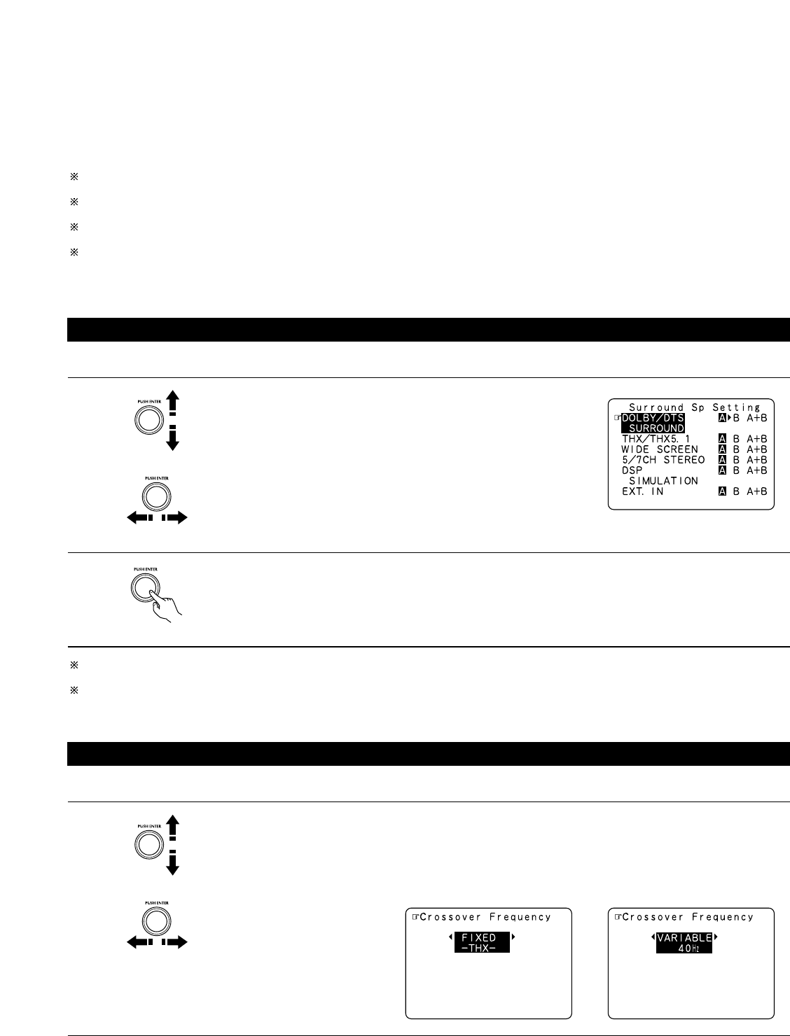
11.Dual Surround Speaker Mode
Provides for the first time the ability to optimize surround sound
reproduction using two different types of surround sound
speakers as well as two different surround speaker positions:
(1) Movie Surround
Motion picture soundtracks use the surround channel(s) to
provide the ambient elements of the acoustic environment
they want the audience to realize. This is best accomplished by
the use of specially-designed surround speakers that offer a
wide diffusion pattern (bipolar dispersion) or by using surround
speakers that provide broad dispersion with a minimum of on-
axis localization (dipolar dispersion). Side wall mounting (closer
to the ceiling) of the surround speakers provides the greatest
envelopment, minimizing localization of direct sound from the
speakers.
(2) Music Surround
With full range discrete surround channels, as well as three
discrete full range front channels, digital formats such as Dolby
and DTS offer thrilling surround sound music listening.
Producers of multi-channel discrete digital music recordings
almost always favor the use of direct radiating (monopolar)
surround speakers, placed in the rear corners of the room,
since that is how they configure their studios during the
mixing/creation process.
The DENON AVR-4802 provides the ability to connect two
different sets of surround speakers, and place them in the
appropriate locations in your home theater room, so that you
can enjoy both movie soundtracks and music listening, with
optimum results and no compromise.
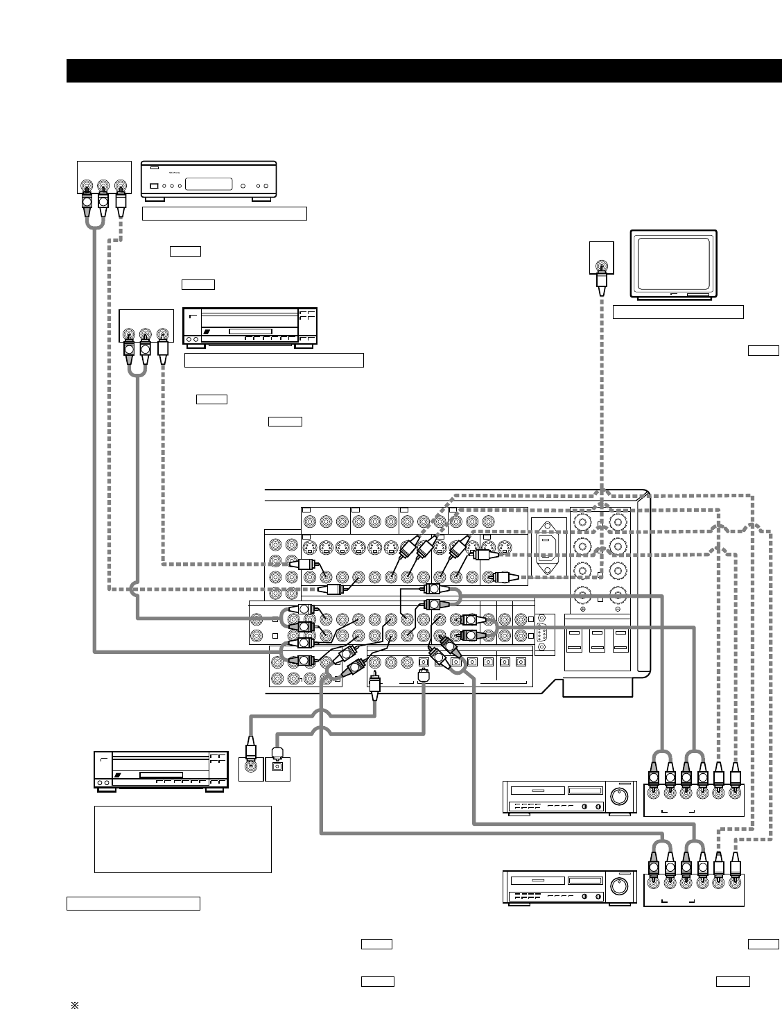
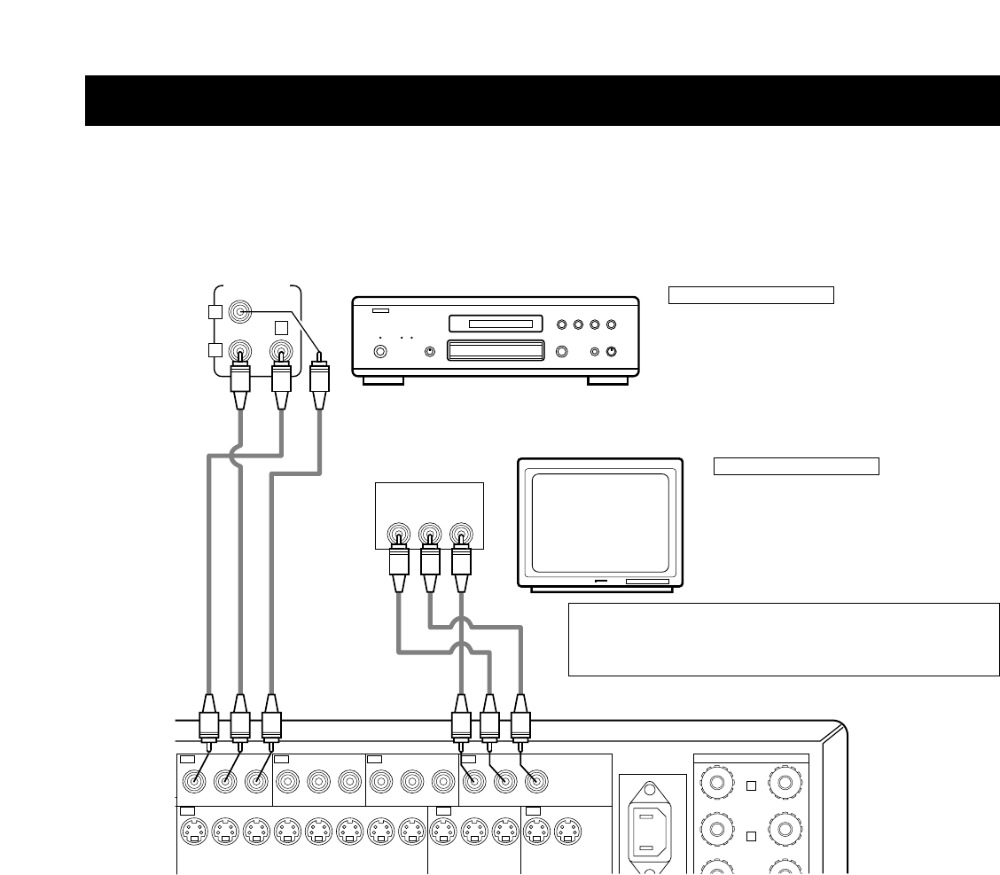
12.Component Video Switching
In addition to composite video and “S” video switching, the AVR-
4802 provides 3 sets of component video (Y, P
R/CR, PB/CB) inputs
for the DVD, TV and DBS/SAT inputs, and one set of component
video outputs to the television, for superior picture quality.
13.Video Select Function
Allow you to watch one source (visual) while listening to another
source (audio).
14.Seven Identical Power Amplifiers
Featuring discrete high current power transistors, the power amp
section is THX Ultra certified for top performance with the widest
range of speaker systems. Rated at 125 watts into 8 /ohms, the
amp channels feature additional low impedance drive capability.
15.Future Sound Format Upgrade Capability via Eight Channel
Inputs & Outputs
For future multi-channel audio format(s), the AVR-4802 is provided
with 7.1 channel (seven main channels, plus one low frequency
effects channel) inputs, along with a full set of 7.1 channel pre-
amp outputs, controlled by the 8 channel master volume control.
This assures future upgrade possibilities for any future multi-
channel sound format.
6
5
CONNECTIONS
Do not plug in the AC cord until all connections have been completed.
Be sure to connect the left and right channels properly (left with left, right with right).
Insert the plugs securely. Incomplete connections will result in the generation of
noise.
Use the AC OUTLETS for audio equipment only. Do not use them for hair
driers, etc.
Note that binding pin plug cords together with AC cords or placing them near a power
transformer will result in generating hum or other noise.
Noise or humming may be generated if a connected audio equipment is used
independently without turning the power of this unit on. If this happens, turn on the
power of the this unit
.
Connecting the audio components
When making connections, also refer to the operating instructions of the other components.
SPEAKER SYSTEMS
PRE OUT
DVD TV MONITOR
YP
B/CB PR/CRYPB/CB PR/CRYPB/CB PR/CRYPB/CB PR/CR
COMPONENT
VIDEO
DBS/
SAT
ANTENNA
AUDIO
DIGITALEXT. IN
FRONT
LOOP ANT.
AM
CENTER
FM COAX. 75
FR FL
SW C
SR SL
SBR SBL
SURROUND
-A
R
R
SURROUND
-B
SIGNAL
GND
PHONO
CD
FRONT CENTER SB
SW
SURROUND
DVD
DVD VDP TV DBS/
SAT
V. AUX VCR-1 VCR-2 VCR-3 VCR-1 VCR-2 VCR-3
S-VIDEO
VIDEO
1-
MONITOR
-2
VDP TV
IN OUT IN
IN OUT RS-232C
OUT
PRE OUT
SPEAKER
IMPEDANCE
FRONT, CENTER,
SB / MULTI
SURROUND
A OR B
6~16
6~16
8~16
A + B
DBS/
SAT
CDR/
TAPE
CDR/
TAPE
MULTI
ZONE
V. AUX VCR-1 VCR-2
COAXIAL
123123 45 54
OPTICAL
VCR-3 VCR-1 VCR-2 VCR-3
R
SB / MULTI
ROOM TO ROOM
POWER
AMP
OUT
OUT IN
R
R
L
R
L
R
L
IN
IN IN IN OUT
OUT OUT
SPEAKER SYSTEMS
AC OUTLETS
AC IN
SWITCHED TOTAL 120W (1A) MAX.
AV 120V 60Hz
FRONT
SURROUND
-A
L
L
SURROUND
-B
L
SB / MULTI
L
REMOTE CONTROL
R
OUTPUT
L
R
L
DIGITAL AUDIODIGITAL AUDIO
RLRL
OUTPUT INPUT
RLRL
OUTPUT INPUT
OPTICALCOAXIAL
OUTPUT
OPTICAL
DIGITAL AUDIODIGITAL AUDIO
B
R
L
RL
R
L
RL
CD player
Connecting a CD player
Connect the CD player’s analog
output jacks (ANALOG OUTPUT) to
this unit’s CD jacks using pin plug
cords.
Connecting a turntable
Connect the turntable’s output cord to the AVR-4802’s PHONO jacks, the
L (left) plug to the L jack, the R (right) plug to the right jack.
NOTE:
This unit cannot be used with MC cartridges directly. Use a separate
head amplifier or step-up transformer.
If humming or other noise is generated when the ground wire is
connected, disconnect the ground wire.
Turntable
(MM cartridge)
Ground wire
Extension jacks for future use
AC cord
(Supplied)
Connecting the pre-out jacks
Use these jacks if you wish to connect external power amplifier(s) to
increase the power of the front, center, surround and surround back sound
channels, or for connection to powered loudspeakers.
When using only one surround back speaker, connect it to left channel.
Connecting the AC OUTLETS
AC OUTLETS
SWITCHED
(total capacity – 120 W (1 A.))
The power to these outlets is turned on and off in conjunction with the POWER
switch on the main unit, and when the power is switched between on and
standby from the remote control unit.
No power is supplied from these outlets when this unit’s power is at standby.
Never connect equipment whose total capacity is above 120 W (1 A.)
NOTE:
Only use the AC OUTLETS for audio equipment. Never use them for hair driers,
TVs or other electrical appliances.
AC outlets (wall)
AC 120V, 60Hz
MD recorder, DAT deck or other component
equipped with digital input/output jacks
CD player or other component equipped
with digital output jacks
Connecting the DIGITAL jacks
Use these for connections to audio equipment with digital output.
Refer to page 29 for instructions on setting this terminal.
NOTES:
Use 75 /ohms cable pin cords for coaxial connections.
Use optical cables for optical connections, removing the cap before connecting.
Connecting a tape deck
Connections for recording:
Connect the tape deck’s recording input jacks (LINE IN or REC) to this
unit’s tape recording (OUT) jacks using pin plug cords.
Connections for playback:
Connect the tape deck’s playback output jacks (LINE OUT or PB) to this
unit’s tape playback (IN) jacks using pin plug cords.
CD recorder or Tape deck
7
Connecting video components
To connect the video signal, connect using a 75 /ohms video signal cable cord. Using an improper cable can result in a drop in picture quality.
When making connections, also refer to the operating instructions of the other components.
PRE OUT
DVD TV MONITOR
YP
B/CB PR/CRYPB/CB PR/CRYPB/CB PR/CRYPB/CB PR/CR
COMPONENT
VIDEO
DBS/
SAT
AUDIO
DIGITALEXT. IN
FR FL
SW C
SR SL
SBR SBL
PHONO
CD
FRONT CENTER SB
SW
SURROUND
DVD
DVD VDP TV DBS/
SAT
V. AUX VCR-1 VCR-2 VCR-3 VCR-1 VCR-2 VCR-3
S-VIDEO
VIDEO
1-
MONITOR
-2
VDP TV
IN OUT IN
IN OUT RS-232C
OUT
PRE OUT
SPEAKER
IMPEDANCE
FRONT, CENTER,
SB / MULTI
SURROUND
A OR B
6~16
6~16
8~16
A + B
DBS/
SAT
CDR/
TAPE
CDR/
TAPE
MULTI
ZONE
V. AUX VCR-1 VCR-2
COAXIAL
123123 45 54
OPTICAL
VCR-3 VCR-1 VCR-2 VCR-3
R
L
R
L
R
L
IN
IN IN IN OUT
OUT OUT
SPEAKER SYSTEMS
AC OUTLETS
AC IN
SWITCHED TOTAL 120W (1A) MAX.
AV 120V 60Hz
FRONT
SURROUND
-A
L
L
SURROUND
-B
L
SB / MULTI
L
L
R
L
R
L
R
R
L
R
L
R OUT IN
AUDIO
VIDEO
OUT IN
LRL
R
L
R
L
R OUT IN
AUDIO
VIDEO
OUT IN
LRL
R
L
R
L
R OUT
VIDEO
OUT
L
AUDIO
L
R
R OUT
VIDEO
OUT
L
AUDIO
L
R
COAXIAL OPTICAL
OUTPUT
L
R
IN
VIDEO
B
TV or DBS/SAT tuner
LD player, CDV player, etc.
Monitor TV
Connecting a TV, DBS/SAT tuner
TV or DBS/SAT
• Connect the TV’s or DBS/SAT tuner’s video output jack (VIDEO OUTPUT) to
the (yellow) TV,DBS/SAT IN jack using a 75 /ohms video coaxial
pin plug cord.
• Connect the TV’s or DBS/SAT tuner’s audio output jacks (AUDIO OUTPUT)
to the TV or DBS/SAT IN jacks using pin plug cords.
AUDIO
VIDEO
Connecting a video disc player VDP
VDP
Connect the video disc player’s video output jack (VIDEO OUTPUT) to the
(yellow) VDP IN jack using a 75 /ohms video coaxial pin plug cord.
Connect the video disc player’s analog audio output jacks (ANALOG AUDIO
OUTPUT) to the VDP IN jacks using pin plug cords.
• A DVD player can be connected to the DVD jacks in the same way.
• It is also possible to connect a video disc player, DVD player, video camcorder,
game machine, etc., to the V.AUX jacks.
AUDIO
VIDEO
MONITOR OUT
• Connect the TV’s video input jack
(VIDEO INPUT) to the
MONITOR OUT jack using a 75
/ohms video coaxial pin plug cord.
• The monitor TV can also be
connected in the same way to the
VIDEO MONITOR OUT-2 jack. Note,
however, that the AVR-4802’s on-
screen display signals are not output
from this jack. (See page 31.)
VIDEO
Note on connecting the digital
input jacks
Only audio signals are input to the
digital input jacks. For details, see
page 6 and page 29.
LD player or other component
equipped with digital output jacks
Video deck 2
Video deck 1
• There are three sets of video deck (VCR) jacks, so three video decks can be connected for simultaneous recording or video copying.
Video input/output connections:
• Connect the video deck’s video output jack (VIDEO OUT) to the (yellow) VCR-1 IN jack, and the video deck’s video input jack (VIDEO IN) to the
(yellow) VCR-1 OUT jack using 75 /ohms video coaxial pin plug cords.
Connecting the audio output jacks
• Connect the video deck’s audio output jacks (AUDIO OUT) to the VCR-1 IN jacks, and the video deck’s audio input jacks (AUDIO IN) to the VCR-1
OUT jacks using pin plug cords.
Connect the another video deck to the VCR-2 or VCR-3 jacks in the same way.
AUDIOAUDIO
VIDEOVIDEO
Connecting a video decks
Connecting a Monitor TV
8
Connecting a video component equipped with S-Video jacks
When making connections, also refer to the operating instructions of the other components.
A note on the S input jacks
The input selectors for the S inputs and pin jack inputs work in conjunction with each other.
Precaution when using S-jacks
This unit’s S-jacks (input and output) and video pin jacks (input and output) have independent circuit structures, so that video signals input from
the S-jacks are only output from the S-jack outputs and video signals input from the pin jacks are only output from the pin jack outputs.
When connecting this unit with equipment that is equipped with S-jacks, keep the above point in mind and make connections according to the
equipment’s instruction manuals.
SPEAKER SYSTEMS
PRE OUT
DVD TV MONITOR
YP
B/CB PR/CRYPB/CB PR/CRYPB/CB PR/CRYPB/CB PR/CR
COMPONENT
VIDEO
DBS/
SAT
ANTENNA
FRONT
LOOP ANT.
AM
CENTER
FM COAX. 75
FR FL
SW C
SR SL
SBR SBL
SURROUND
-A
R
R
SURROUND
-B
DVD VDP TV DBS/
SAT
V. AUX VCR-1 VCR-2 VCR-3 VCR-1 VCR-2 VCR-3
S-VIDEO
VIDEO
1-
MONITOR
-2
R
SB / MULTI
ROOM TO ROOM
POWER
AMP
OUT
OUT IN
R
IN
IN IN IN OUT
OUT OUT
REMOTE CONTROL
OUT
S-VIDEO
IN
S-VIDEO
OUT
S-VIDEO
IN OUT
S-VIDEO
IN OUT
S-VIDEO
B
LD player, CDV player, etc.
Monitor TV
Video deck 2
Video deck 1
TV or satellite broadcast tuner
Connecting a video disc player (VDP)
Connecting a monitor TV
Connecting the video decks
Connecting a TV, DBS/SAT tuner
VDP
Connect the video disc player’s S-Video output jack to the
S-VIDEO VDP IN jack using an S-Video connection cord.
A DVD player can be connected to the DVD jacks in the same
way.
• It is also possible to connect a video disc player, DVD player,
video camcorder, game machine, etc., to the V.AUX jacks.
MONITOR OUT
• Connect the TV’s or DBS tuner’s S video input (S-VIDEO INPUT)
to the MONITOR OUT-1 jack using a S jack connection
cord.
The monitor TV can also be connected in the same way to the S-
VIDEO MONITOR OUT-2 jack. Note, however, that the AVR-
4802’s on-screen display signals are not output from this jack.
S-VIDEO
Connect the TV’s or DBS tuner’s S video output jack
(S-VIDEO OUTPUT) to the TV, DBS/SAT
IN jack using an S jack connection cord.
S-VIDEO
• Connect the video deck’s S output jack (S-OUT) to the VCR-1 IN jack and
the video deck’s S input jack (S-IN) to the VCR-1 OUT jack using S jack
connection cords.
• Connect the video deck’s S output jack (S-OUT) to the VCR-2 IN jack and
the video deck’s S input jack (S-IN) to the VCR-2 OUT jack using S jack
connection cords.
S-VIDEO
S-VIDEO
S-VIDEO
S-VIDEO
Connect the components’ audio inputs and outputs as described on page 7.
NOTES:
The on-screen display signals are not output from the video signal MONITOR OUT-2 (yellow) or S-Video signal MONITOR OUT-2 jack.
The MONITOR OUT-2 output switches together with the input function selected with the REC/MULTI button. To use as the monitor output,
set “SOURCE” as the REC/MULTI input function.
9
Connecting a Video Component Equipped with Color Difference (Component - Y, P
B
/C
B
, P
R
/C
R
)
Video Jacks (DVD Player)
When making connections, also refer to the operating instructions of the other components.
The signals input to the color difference (component) video jacks are not output from the VIDEO output jack (yellow) or the S-Video output jack.
In addition, the video signals input to the VIDEO input (yellow) and S-Video input jacks are not output to the color difference (component) video
jacks.
The AVR-4802’s on-screen display signals are not output from the color difference (component) video output jacks (MONITOR OUT).
Some video sources with component video outputs are labeled Y, Pb, Pr, or Y, Cb, Cr, or Y, R-Y, B-Y. These terms all refer to component video
color difference output.
YPrPb
B
B
VIDEO OUT
Pr
Y
Pb
COMPONENT
VIDEO IN
COMPONENT
DVD player
Monitor TV
Connecting a DVD player
Connecting a monitor TV
DVD IN jacks
Connect the DVD player’s color difference
(component) video output jacks (COMPONENT VIDEO
OUTPUT) to the COMPONENT DVD IN jack using 75 /
ohms coaxial video pin-plug cords.
• In the same way, another video source with component
video outputs such as a TV, DBS/SAT tuner, etc., can be
connected to the TV, DBS/SAT color difference
(component) video jacks.
MONITOR OUT jack
Connect the TV’s color difference (component)
video input jacks (COMPONENT VIDEO INPUT)
to the COMPONENT MONITOR OUT jack using
75 /ohms coaxial video pin-plug cords.
The color difference input jacks may be indicated differently on some TVs,
monitors or video components (“Pr, Pb and Y”, “R-Y, B-Y and Y”, “Cr, Cb and
Y”, etc.). For details, carefully read the operating instructions included with
the TV or other component.
10
1
4
2
3
Connecting the antenna terminals
SPEAKER SYSTEMS
PRE OUT
DVD
YP
B/CB PR/CR
ANTENNA
EXT. IN
FRONT
LOOP ANT.
AM
CENTER
FM COAX. 75
FR FL
SW C
SR SL
SBR SBL
SURROUND
-A
R
R
SURROUND
-B
SIGNAL
GND
PHONO
CD
FRONT CENTER SB
SW
SURROUND
DVD
DVD VDP TV
VDP TV
I
R
SB / MULTI
ROOM TO ROOM
POWER
AMP
OUT
OUT IN
R
R
L
R
L
IN
IN
REMOTE CONTROL
DIRECTION OF
BROADCASTING
STATION
AM LOOP ANTENNA
(Supplied)
FM ANTENNA
GROUND
AM OUTDOOR
ANTENNA
FM INDOOR
ANTENNA
(Supplied)
300 /ohms
FEEDER
CABLE
75 /ohms
COAXIAL
CABLE
F-type converter plug (attached)
When using the FM antenna
attach to this apparatus
AM loop antenna assembly
Connect to the AM
antenna terminals.
Bend in the reverse
direction.
Remove the vinyl tie
and take out the
connection line.
a. With the antenna
on top any stable
surface.
b. With the antenna
attached to a
wall.
Mount
Installation hole
Mount on wall, etc.
Connection of AM antennas
1. Loosen by turning
counterclockwise.
2. Insert the
cord.
3. Tighten by turning
clockwise.
Note to CATV system installer:
This reminder is provided to call the CATV system installers
attention to Article 820-40 of the NEC which provides
guidelines for proper grounding and, in particular, specifies
that the cable ground shall be connected to the grounding
system of the building, as close to the point of cable entry as
practical.
Notes:
Do not connect two FM antennas simultaneously.
Even if an external AM antenna is used, do not disconnect
the AM loop antenna.
Make sure AM loop antenna lead terminals do not touch
metal parts of the panel.
11
Connecting the external input (EXT. IN) jacks
Connecting the MULTI SOURCE jacks
These jacks are for inputting multi-channel audio signals from an outboard decoder, or a component with a different type of multi-channel
decoder, such as a Super Audio DVD player, or a multi-channel SACD player, or other future multi-channel sound format decoder.
When making connections, also refer to the operating instructions of the other components.
If another amplifier is connected, the multi-source jacks can be used to play a different program source in another room at the same time. (See
page 40.)
ANTENNA
AUDIO
DIGITALEXT. IN
SR SL
SBR SBL
SURROUND
-A
R
SURROUND
-B
SIGNAL
GND
PHONO
CD
FRONT CENTER SB
SW
SURROUND
DVD
DVD VDP TV DBS/
SAT
V. AUX VCR-1 VCR-2 VCR-3 VCR-1 VCR-2 VCR-3
VDP TV
IN OUT
IN
DBS/
SAT
V. AUX VCR-1 VCR-2
COAXIAL
1231234
OPTICAL
VCR-3 VCR-1 VCR-2 VCR-3
R
SB / MULTI
ROOM TO ROOM
POWER
AMP
OUT
OUT IN
R
R
L
R
L
REMOTE CONTROL
R
L
R
L
R
L
Decoder with 8- or 6-channel
analog output
Front
Surround back
Surround
Subwoofer
Center
For instructions on playback using the external input (EXT. IN) jacks, see page 38.
ANTENNA
AUDIO
DIGITALEXT. IN
CENTER
FM COAX. 75
SW C
SR SL
SBR SBL
SURROUND
-A
R
SURROUND
-B
SIGNAL
GND
PHONO
CD
FRONT CENTER SB
SW
SURROUND
DVD
DVD VDP TV DBS/
SAT
V. AUX VCR-1 VCR-2 VCR-3 VCR-1 VCR-2 VCR-3
S-VIDEO
VIDEO
1-
MONITOR
-2
VDP TV
IN OUT IN
IN OUT RS-232C
OUT
PRE OUT
SPEAKER
IMPEDANCE
FRONT, CENTER,
SB / MULTI
SURROUND
A OR B
6~16
6~16
8~16
A + B
DBS/
SAT
CDR/
TAPE
CDR/
TAPE
MULTI
ZONE
V. AUX VCR-1 VCR-2
COAXIAL
123123 45 54
OPTICAL
VCR-3 VCR-1 VCR-2 VCR-3
R
SB / MULTI
ROOM TO ROOM
POWER
AMP
OUT
OUT IN
R
R
L
R
L
R
L
AC OUTLETS
AC IN
SWITCHED TOTAL 120W (1A) MAX.
AV 120V 60Hz
-
A
L
SURROUND
-B
L
SB / MULTI
L
REMOTE CONTROL
L
R
++
OUTPUT
INPUT
AUX OUT
B
Another room
RC-616
INFRARED
RETRANSMITTER
Integrated pre-main amplifier
RC-617
INFRARED SENSOR
Extension jacks for future use.
For instructions on operations using the MULTI SOURCE jacks, see page 37.
12
Speaker system connections
Connect the speaker terminals with the speakers making sure that like
polarities are matched ( < with < , > with > ). Mismatching of polarities will
result in weak central sound, unclear orientation of the various instruments,
and the sense of direction of the stereo being impaired.
When making connections, take care that none of the individual conductors
of the speaker cord come in contact with adjacent terminals, with other
speaker cord conductors, or with the rear panel.
Speaker Impedance
Speakers with an impedance of from 6 to 16 /ohms can be connected for
use as front and center speakers.
Speakers with an impedance of 6 to 16 /ohms can be connected for use
as surround speakers.
The protector circuit may be activated if the set is played for long periods of
time at high volumes when speakers with an impedance lower than the
specified impedance are connected.
NOTE:
NEVER touch the speaker terminals when the power is on.
Doing so could result in electric shocks.
Connecting the speaker cords
1. Loosen by turning
counterclockwise.
2. Insert the cord. 3. Tighten by turning
clockwise.
Either tightly twist or terminate the core wires.
Connecting banana plugs
Turn clockwise to tighten, then insert the
banana plug.
Protector circuit
This unit is equipped with a high-speed protection circuit. The purpose of this circuit is to protect the speakers under
circumstances such as when the output of the power amplifier is inadvertently short-circuited and a large current flows,
when the temperature surrounding the unit becomes unusually high, or when the unit is used at high output over a long
period which results in an extreme temperature rise.
When the protection circuit is activated, the speaker output is cut off and the power supply indicator LED flashes. Should
this occur, please follow these steps: be sure to switch off the power of this unit, check whether there are any faults
with the wiring of the speaker cables or input cables, and wait for the unit to cool down if it is very hot. Improve the
ventilation condition around the unit and switch the power back on.
If the protection circuit is activated again even though there are no problems with the wiring or the ventilation around the
unit, switch off the power and contact a DENON service center.
Note on speaker impedance
The protector circuit may be activated if the set is played for long periods of time at high volumes when speakers with
an impedance lower than the specified impedance (for example speakers with an impedance of lower than 4 /ohms)
are connected. If the protector circuit is activated, the speaker output is cut off. Turn off the sets power, wait for the set
to cool down, improve the ventilation around the set, then turn the power back on.
13
Connections
When making connections, also refer to the operating instructions of the other components.
SPEAKER SYSTEMS
PRE OUT
DVD TV MONITOR
YP
B/CB PR/CRYPB/CB PR/CRYPB/CB PR/CRYPB/CB PR/CR
COMPONENT
VIDEO
DBS/
SAT
ANTENNA
AUDIO
DIGITALEXT. IN
FRONT
LOOP ANT.
AM
CENTER
FM COAX. 75
FR FL
SW C
SR SL
SBR SBL
SURROUND
-A
R
R
SURROUND
-B
SIGNAL
GND
PHONO
CD
FRONT CENTER SB
SW
SURROUND
DVD
DVD VDP TV DBS/
SAT
V. AUX VCR-1 VCR-2 VCR-3 VCR-1 VCR-2 VCR-3
S-VIDEO
VIDEO
1-
MONITOR
-2
VDP TV
IN OUT IN
IN OUT RS-232C
OUT
PRE OUT
SPEAKER
IMPEDANCE
FRONT, CENTER,
SB / MULTI
SURROUND
A OR B
6~16
6~16
8~16
A + B
DBS/
SAT
CDR/
TAPE
CDR/
TAPE
MULTI
ZONE
V. AUX VCR-1 VCR-2
COAXIAL
123123 45 54
OPTICAL
VCR-3 VCR-1 VCR-2 VCR-3
R
SB / MULTI
ROOM TO ROOM
POWER
AMP
OUT
OUT IN
R
R
L
R
L
R
L
IN
IN IN IN OUT
OUT OUT
SPEAKER SYSTEMS
AC OUTLETS
AC IN
SWITCHED TOTAL 120W (1A) MAX.
AV 120V 60Hz
FRONT
SURROUND
-A
L
L
SURROUND
-B
L
SB / MULTI
L
REMOTE CONTROL
(
L
) (
L
) (
R
) (
R
)
(
L
) (
R
) (
L
) (
R
)
Connection jack for
subwoofer with built-in
amplifier (super woofer),
etc.
SURROUND SPEAKER
SYSTEMS (A)
CENTER SPEAKER SYSTEMFRONT SPEAKER SYSTEMS
Precautions when
placing speakers
If a speaker is placed near
a TV or video monitor, the
colors on the screen may
be disturbed by the
speakers magnetism. If
this should happen, move
the speaker away to a
position where it does not
have this effect.
IN
SURROUND SPEAKER
SYSTEMS (B)
SURROUND BACK
SPEAKER SYSTEMS
NOTE:
When using only one surround back speaker, connect it to left channel.
14
6
PART NAMES AND FUNCTIONS
Front Panel
For details on the functions of these parts, refer to the pages given in parentheses ( ).
MASTER VOLUME
INPUT SELECTOR
ON/STANDBY
THX CINEMA
HOME
PURE
DIRECT
PHONES
CONTROL
TONE
TUNING
PRESET
SELECT
CH. VOL
REC / MULTI
PARAMETER
SURROUND
STATUS
DEFEAT
TONE
DIMMER
SIMULATION
ON/OFF
DSP
VIDEO
STEREO
5CH / 7CH
VIDEO
SELECT
WIDE
CINEMA
SCREEN
/ MUSIC
EXT. IN
DOLBY / DTS
STEREO
ANALOG
DIRECT
INPUT MODE
INPUT
SURROUND MODE
MULTI FUNCTION
SENSOR
REMOTE
ON/STANDBY
INPUT
SIGNAL
PCM
AUTO
DTS
DIRECT
PURE
DIGITAL
SURROUND SPEAKER
A
B
SURROUND BACK CH
OUTPUT
DETECT
SIGNAL
ES DSCRT DVD
VOLUME LEVEL
DIGITAL
#6 #5
#4
#3#2 #0 @9#1 @8 @7 @6 @5 @4
qw
e
rtyuio!0 !1 !2 !3 !5!4
!6 !7 !8 !9 @0 @1 @2 @3
q
Power ON/STANDBY switch.......................................(18, 32, 59)
w
Headphones jack (PHONES)....................................................(35)
e
DIRECT button ................................................(34, 36, 39, 53, 59)
r
INPUT MODE selector button.........................(33, 36, 38, 45, 47)
t
ANALOG button ................................................................(33, 38)
y
EXT. IN button ...................................................................(33, 38)
u
CINEMA/MUSIC button...........................................................(49)
i
VIDEO SELECT button ............................................................(35)
o
VIDEO ON/OFF button ............................................................(39)
!0
DIMMER button ......................................................................(35)
!1
STATUS button ........................................................................(35)
!2
REC/MULTI button.............................................................(36, 37)
!3
SELECTOR dial (SELECTOR) ........(34, 36, 37, 42, 43, 51, 58, 59)
!4
TUNING PRESET button....................................................(58, 59)
!5
TONE CONTROL button..........................................................(34)
!6
STEREO button ...............................................(34, 36, 39, 53, 59)
!7
DOLBY/DTS button .........................................(34, 47, 49, 51, 53)
!8
WIDE SCREEN button.......................................................(34, 53)
!9
5CH/7CH STEREO button .................................................(34, 53)
@0
DSP SIMULATION button .................................................(34, 53)
@1
TONE DEFEAT button .............................................................(35)
@2
SURROUND PARAMETER button.....................................(50, 51)
@3
Channel Volume button (CH VOL).....................................(42, 43)
@4
MASTER VOLUME control................................................(34, 35)
@5
Master volume indicator (VOLUME LEVEL)............................(34)
@6
Display ...............................................................................(36, 37)
@7
Input mode indicators (INPUT MODE) ....................................(34)
@8
Surround speaker system indicators
(SURROUND SPEAKER A/B)
@9
Surround back ch indicators ..............................................(46, 47)
#0
PURE DIRECT indicator ...........................................................(39)
#1
Digital signal indicators (SIGNAL)................................(34, 46, 47)
#2
Remote control sensor (REMOTE SENSOR) ..........................(31)
#3
Power indicator........................................................................(32)
#4
PURE DIRECT button ..............................................................(39)
#5
Input source selector dial
(INPUT SELECTOR).........................................(33, 45, 47, 49, 57)
#6
HOME THX CINEMA button .............................................(45, 46)
15
Remote control unit
For details, refer to the separate (supplied) RC-8000 operating instructions.
q
w
e
r
t
i
u
y
o
!0
!1
!2
The USB terminal is a terminal that will be used in the future to update the microprocessor program, etc.
q
Transmitter
w
Touch panel
e
CHANNEL up/down buttons
r
MUTE button
t
USB terminal
y
Jog stick (PUSH ENTER)
u
VOL. (volume) up/down buttons
i
LIGHT (back light) button
o
Battery charging contacts
!0
RF frequency selector switch
!1
Reset button
!2
Battery cover
16
7
SETTING UP THE SYSTEM
Once all connections with other AV components have been completed as described in CONNECTIONS (see pages 6 to 13), make the
various settings described below on the monitor screen using the AVR-4802s on-screen display function.
These settings are required to set up the listening rooms AV system centered around the AVR-4802.
Use the following buttons to set up the system:
System setup items and default values (set upon shipment from the factory)
System setup Default settings
q
w
t
y
u
i
o
Speaker
Configuration
(Surround
Speaker
Setting)
Subwoofer mode
SB CH Auto
Flag Detect
Channel
Level
Subwoofer
Peak Limit
Lev
Digital In
Assignment
On Screen
Display
Auto Tuner
Presets
Input the combination of speakers in your system and their
corresponding sizes (SMALL for regular speakers, LARGE for full-
size, full-range) to automatically set the composition of the signals
output from the speakers and the frequency response.
Use this function when using multiple surround speaker
combinations for more ideal surround sound. Once the
combinations of surround speakers to be used for the
different surround modes are preset, the surround
speakers are selected automatically according to the
surround mode.
This selects the subwoofer speaker for playing deep bass signals.
Set the method of playing the surround back channel for digital
signals.
This adjusts the volume of the signals output from the speakers and
subwoofer for the different channels in order to obtain optimum
effects.
This parameter is for detecting the maximum level of the low bass
signals output from the subwoofer channel in order to protect the
subwoofer from damage and prevent unpleasant distorted sounds
from being produced.
This assigns the digital input jacks for the different input
sources.
This sets whether or not to display the on-screen display that
appears on the monitor screen when the controls on the remote
control unit or main unit are operated (from MONITOR 1 outputs
only).
FM stations are received automatically and stored in the memory.
Surround
mode
Surround
speaker
Input
source
Digital
Inputs
Front Sp.
Small
Center Sp. Surround Sp.Subwoofer
Small SmallYes
DOLBY/
DTS
SURROUND
THX /
THX 5.1
WIDE
SCREEN
5CH/7CH
STEREO
DSP
SIMULATION
EXT. IN
——
A A AAAA ——
LFE THX
Front L & R Center Surround L & RSubwoofer
12 ft (3.6 m) 12 ft (3.6 m) 10 ft (3.0 m)12 ft (3.6 m)
Front L
Front R Center
Surround
R
Surround
Back R
Subwoofer
0 dB 0 dB 0 dB 0 dB 0 dB 0 dB
Peak Limitter = OFF
CD DVD VDP TV
DBS/SAT
VCR-1 VCR-2
V. AUX
COAXIAL
1
COAXIAL
2
COAXIAL
3
OPTICAL
1
OPTICAL
2
OPTICAL
3
OPTICAL
4
OFF
On Screen Display = ON
A1 ~ A8
B1 ~B8
C1 ~C8
D1 ~D8
E1 ~E8
87.5/89.1/98.1/107.9/90.1/90.1/90.1/90.1 MHz
520/600/1000/1400/1500/1710 kHz/90.1/90.1 MHz
90.1 MHz
90.1 MHz
90.1 MHz
Surround Sp Back.
Small / 2spkrs
Auto Flag Detect Mode = ON / Non-Flag Source SBch Output = THX Surround EX DTS ES
e
Delay Time
This parameter is for optimizing the timing with which the audio
signals are produced from the speakers and subwoofer according to
the listening position.
SBL & SBR
10 ft (3.0 m)
r
Multi Zone
Control
This sets the output level for the multi-zone 1
output jacks.
Variable
Surround
Back L
0 dB
Surround
L
0 dB
Multi Zone-1
vol. Level
Power AMP
Assignment
Set this to switch the surround back channels
power amplifier for use for multi-zone 2.
Surround Back
TAPE
OPTICAL
5
Screen while icons are displayed
Transmission codes
of independent buttons
CHANNEL : Tuner preset
CHANNELª : Tuner preset
VOL : Main volume of AV amplifier
VOLª : Main volume of AV amplifier
MUTE : Muting of AV amplifier
VCR-3
OFF
Crossover
Frequency
Set the crossover frequency according to the speakers bass
playback ability.
FIXED THX
17
Speaker system layout
Basic system layout (For a THX Surround EX system)
The following is an example of the basic layout for a system consisting of eight speaker systems and a television monitor:
With the AVR-4802 it is also possible to use the surround speaker selector function to choose the best layout for a variety of sources and surround
modes.
Subwoofer Center speaker system
Surround speaker systems
Surround back speaker systems
Front speaker systems
Set these at the sides of the TV or screen with
their front surfaces as flush with the front of the
screen as possible.
Surround speaker selector function
This function makes it possible to achieve the optimum sound fields for different sources by switching between two systems of surround
speakers (A and B). The settings of the different speakers (A only, B only or A+B) are stored in the memory for the different surround modes,
so they are set automatically when the surround mode is selected.
AA
BB
AA
BB
SB SB SB SB
Using A only
(Multi surround speaker system)
Using B only
(Single surround speaker system)
(SB: Surround Back Speakers)
NOTES:
The on-screen display signals are not output from the MONITOR OUT-2 output jack or the color difference (component) video signal (MONITOR OUT) jacks.
The on-screen display signals are output with priority to the S-VIDEO MONITOR OUT jack during playback of a video component. For example, if the TV
monitor is connected to both the AVR-4802s S-Video and video monitor output jacks and signals are input to the AVR-4802 from a video source (VDP, etc.)
connected to both the S-Video and video input jacks, the on-screen display signals are output with priority to the S-Video monitor output. If you wish to output
the signals to the video monitor output jack, do not connect a cord to the S-VIDEO MONITOR OUT jack. (For details, see page 31.)
The AVR-4802s on-screen display function is designed for use with high resolution monitor TVs, so it may be difficult to read small characters on TVs with small
screens or low resolutions.
The setup menu is not displayed when headphones are being used.
18
Before setting up the system
1
Check that all the connections are
correct, then turn on the main units
power.
2
Either lightly press on the remote control units touch panel
or press the LIGHT button to turn on the liquid crystal display.
(The back light does not turn on when the touch panel is
pressed.)
3
By default the liquid crystal display is set to display for 30
seconds, but this can be changed to approximately 120
seconds using the procedure described below so that
operations during system up can be performed securely.
4
Lightly press the remote control units
jog stick (PUSH ENTER) to display the
icon display section.
5
Press the “” button in the icon display section to display
the SETUP icon.
6
Press the SETUP icon for at least 3 seconds to display
the setup screen.
8
Press the “” button in the icon display section to display
the AVAMP icon.
Press the AVAMP icon to display the page section.
ON / STANDBY
(Main unit)
1
7
Push the remote control units jog
stick to the right to display the SETUP
4/4 page.
Press the LCD 30s button on this
page so that this part is displayed in
half-tone dot mesh.
Now press the button to set the
time display to 120s.
Push the remote control units jog stick
to the right to display the SETUP 3/5
page.
Press SYSTEM SETUP at the bottom left to display the
System Setup Menu on the TV screen.
2
2, 5, 6, 7, 8
4, 7, 8
19
Setting the type of speakers
The composition of the signals output from the different channels and the frequency response are adjusted automatically according to the
combination of speakers actually being used.
2
At the System Setup Menu select Speaker Configuration.
3
Switch to the speaker configuration screen.
4
Set whether or not speakers are
connected and, if so, their size
parameters.
To select the speaker
To select the parameter
Center Sp.
Front Sp.
Subwoofer
Surround Sp. A
Surround back Sp.
Surround Sp. B
1
Press CURSOR/PAGE at the center of the bottom line on the AV AMPs SETTING 3/5 page so
that this part is displayed in half-tone dot mesh.
Make the system setups by pushing the jog stick on the remote control unit forward and backward, left
and right.
5
Enter the setting.
a) If no surround speakers are used (if None is set for both A and B):
The System Setup Menu reappears.
b) If both surround speakers A and B are used (if either Large or Small is set for both A and B):
The surround speaker setting screen appears.
c) When Front is set to Large and Subwoofer is set to Yes, the set switches to the subwoofer mode.
d) If None is set for surround speakers A:
None is automatically set for surround speakers B and surround back speaker.
NOTE:
Select Large or Small not according to the actual size of the speaker but according to the speakers capacity for playing low frequency
(bass sound below frequency set for the Crossover Frequency mode and below) signals. If you do not know, try comparing the sound at both
settings (setting the volume to a level low enough so as not to damage the speakers) to determine the proper setting.
20
Parameters
Large ................Select this when using speakers that have sufficient performance for reproducing bass sound below the frequency set for
the Crossover Frequency mode.
Small ................Select this when using speakers that do not have sufficient performance for reproducing bass sound below the frequency
set for the Crossover Frequency mode. When this is set, bass sound with a frequency below the frequency set for the
Crossover Frequency mode is sent to the subwoofer or main speakers selected Large.
None…… .........Select this when no speakers are installed.
Yes/No ..........Select Yes when a subwoofer is installed, No when a subwoofer is not installed.
2spkrs/1spkr.....Select the number of speakers to be used for the surround back channel.
If the subwoofer has sufficient low frequency playback capacity, good sound can be achieved even when Small is set for the front, center
and surround speakers.
To take full advantage of the performance of the Home THX certified speaker systems, set the front, center and surround speaker size
parameters to Small and the subwoofer to Yes.
For the majority of speaker system configurations, using the SMALL setting for all five main speakers and Subwoofer On with a connected
subwoofer will yield the best results.
When Front is set to Small, Subwoofer is automatically set to Yes, and when Subwoofer is set to No, Front is automatically
set to Large.
Selecting the surround speakers for the different surround modes
At this screen preset the surround speakers to be used in the different surround modes.
1
When either Large or Small has been set for both speakers A and B
on the System Setup Menu (when using both A and B surround speakers),
the surround speaker setting screen appears.
Select the surround speakers to be used in the different surround modes.
To select the surround mode
To select the surround speaker
A: When using surround speakers A
B: When using surround speakers B
A+B: When using both surround speakers A and B
2
Enter the setting.
When Subwoofer is set to Yes or other speakers is set to Small, the set switches to the Crossover
Frequency mode.
When Front is set to Large and Subwoofer is set to Yes, the set switches to the subwoofer mode.
(See page 21.)
Speaker type setting when using both surround speakers A and B
If Small is set for either surround speakers A or B, the output is the same as when Small is set for both A and B.
For the WIDE SCREEN and 5/7CH STEREO DSP simulation modes, the surround speakers can be set separately.
Setting the Crossover Frequency
1
Select the Crossover Frequency mode.
Set the crossover frequency mode according to the speaker system being used.
To select the Crossover Frequency.
21
2
Enter the setting.
The System Setup Menu reappears.
Crossover frequency
Set the frequency (Hz) below which the bass sound of each main speakers is to output from the subwoofer or from speakers which are set to
Large (when not using a subwoofer) (crossover frequency).
For speakers set to Small, sound with a frequency below the crossover frequency is cut, and instead the cut bass sound is output from the
subwoofer or speakers which are set to Large.
This crossover frequency mode is valid when Subwoofer is set to Yes at Speaker Configuration Setting or when speakers are set to
Small.
FIXED THX:
Set to the THX rated 80 Hz crossover frequency.
VARIABLE 40, 60, 80, 100, 120 Hz:
Set as desired according to your speakers bass playback ability.
NOTES:
The crossover frequency is set to 80 Hz in the HOME THX CINEMA mode.
We recommend using with the crossover frequency set to FIXED THX–”, but depending on the speaker, setting it to a different frequency
may improve frequency response near the crossover frequency.
Setting the Subwoofer mode
1
Select the subwoofer mode.
2
Enter the setting.
The System Setup Menu reappears.
NOTES:
Assignment of low frequency signal range
The only signals produced from the subwoofer channel are LFE signals (during playback of Dolby Digital or DTS signals) and the low
frequency signal range of channels set to Small in the setup menu. The low frequency signal range of channels set to Large are
produced from those channels.
Subwoofer mode
The subwoofer mode setting is only valid when Large is set for the front speakers and Yes is set for the subwoofer in the Speaker
Configuration settings (see page 19).
When the LFE+Main playback mode is selected, the low frequency signal range of channels set to Large are produced simultaneously
from those channels and the subwoofer channel.
In this playback mode, the low frequency range expand more uniformly through the room, but depending on the size and shape of the room,
interference may result in a decrease of the actual volume of the low frequency range.
Selection of the LFE - THX play mode will play the low frequency signal range of the channel selected with Large from that channel
only. Therefore, the low frequency signal range that are played from the subwoofer channel are only the low frequency signal range of LFE
(only during Dolby Digital or DTS signal playback) and the channel specified as Small in the setup menu. THX is recommended in this play
mode so that bass interference is less likely to occur in the room.
Select the play mode that provides bass reproduction with body.
22
Setting the THX Surround EX / DTS-ES Source Auto
Set the operation for the digital signals when playing in the 6.1 SURROUND, DTS-ES and THX SURROUND EX surround modes.
1
At the System Setup Menu select SB CH Auto Flag
Detect and press the ENTER button.
2
Select the desired setting.
When set to ON, the
operation for software for which
no identification signals are
recorded is set.
3
Enter the setting.
The System Setup Menu reappears.
THX surround EX/DTS ES Auto Flag Detect Mode (AFDM) setting
ON .................This function only works with software on which a special identification signal is recorded.
This is a function for automatically playing in the 6.1-channel mode using the surround back speakers if the software is recorded
in THX Surround EX or DTS-ES or in the normal 5.1-channel mode without using the surround back speakers when the software
is not recorded in THX Surround EX or DTS-ES.
OFF................Set the OFF mode to perform 6.1-channel playback with conventional 5.1-channel sources or sources on which the
identification signal described below is not recorded.
Non-Flag Source SB ch Output setting
THX surround EX/DTS ES..........Playback is conducted using the surround back speaker.
Surround back channel is reproduced using digital matrix processing.
Non MTRX.....Playback is conducted using the surround back speaker. The same signals as those of the surround channels are output from
the surround back channel.
OFF................Playback is conducted without using the surround back speaker.
NOTES:
The SB CH Auto Flag Detect setting screen is displayed when the surround back speaker is set to Large or Small at Speaker
Configuration.
The surround back speakers can also be turned on and off using the SB CH OUT surround parameter. (See pages 55.)
Select the setting according to the program source to be played.
23
Setting the delay time
Input the distance between the listening position and the different speakers to set the delay time for the surround mode.
The delay time can be set separately for surround speakers A and B.
Preparations:
Measure the distances between the listening position and the speakers (L1 to L5 on the diagram at
the right).
L1: Distance between center speaker and listening position
L2: Distance between front speakers and listening position
L3: Distance between surround speakers and listening position
L4: Distance between surround back speakers and listening position
L5: Distance between subwoofer and listening position
L1
L2
L5
L3
L4
1
At the System Setup Menu select Delay Time.
Center FRFL
Subwoofer
SL
Listening position
SR
SBRSBL
2
Switch to the Delay Time screen.
3
Select the desired unit, meters or feet.
Select (darken) the desired units, Meters or Feet.
4
Once Meter or Feet is selected in Step 3, the
Delay Time screen appears automatically.
5
At the System Setup Menu select Delay Time.
Example: When Feet is selected
24
6
Set the distance between the
center speaker and listening
position.
The distance changes in units of 1
foot (0.1 meters) each time the
button is pressed. Select the value
closest to the measured distance.
If Yes is selected for Default, the settings are automatically reset
to the default values.
Please note that the difference of distance for every speaker should be 15
ft (4.5 m) or less. If you set an invalid distance, a CAUTION notice, such
as screen right will appear. In this case, please relocate the blinking
speaker(s) so that its distance is no larger than the value shown in
highlighted line.
Example: When the distance is set to 12 feet
for the center speaker
7
Enter the setting.
The System Setup Menu reappears.
The AVR-4802 automatically sets the optimum surround delay time for the listening room.
Setting the Multi Zone Control
Multi-zone is a pre-output with an output level adjustment function.
Using the power amplifier assignment function described below, it is also possible to connect speakers to the SB/MULTI speaker terminals.
Make this setting to switch the power amplifier for the surround back channel to Multi-zone.
[1] Power amplifier assignment function setting
1
At the System Setup Menu, select Multi Zone Control.
2
Press jog stick ENTER to switch to the Multi Zone Control screen.
3
Select Power Amp Assignment then press the ENTER button on the jog stick.
25
1
At the System Setup Menu, select Multi Zone Control.
2
Press jog stick ENTER to switch to the Multi Zone Control screen.
[2] Setting the multi-zone level
3
Select Multi Zone Vol. Level then press jog stick ENTER.
4
Select Surround Back to use as the surround back
channel, Multi to use as multi-zone, then press jog
stick ENTER.
When Surround Back is selected When Multi is selected
4
Select the desired setting, then press jog stick ENTER.
Variable:
The level can be adjusted freely using the buttons on the remote control unit (M. ZONE 1 4/5,
VOLUME UP and VOLUME DOWN).
-40 dB, 0 dB:
The output level is fixed at the set level and the volume can no longer be adjusted.
NOTE: The multi zone volume level is not displayed when Multi is selected at the Power
Amp Assignment setting.
26
Setting the channel level
Use this setting to adjust so that the playback level between the different channels is equal.
From the listening position, listen to the test tones produced from the speakers to adjust the level.
The level can also be adjusted directly from the remote control unit. (For details, see page 42.)
When using both surround speakers A and B, their playback levels can be adjusted separately.
1
At the System Setup Menu select Channel Level.
2
Switch to the Channel Level screen.
3
Select Test Tone Mode.
4
Select the mode.
Select Auto or Manual.
Auto:
Adjust the level while listening to the test tones produced automatically
from the different speakers.
Manual:
Select the speaker from which you want to produce the test tone to
adjust the level.
Example: When the Auto mode is selected
5
Select Surr. Sp., then select the surround speaker(s) from which you want to produce the test
tone (A, B or A+B).
Surr. Sp.: A
Adjusts the balance of the playback level between the channels when using surround speaker
A.
Surr. Sp.: B
Adjusts the balance of the playback level between the channels when using surround speaker
B.
Surr. Sp.: A+B
Adjusts the balance of the playback level between the channels when using surround
speakers A and B at the same time.
The Surr. Sp. can only be selected when both surround speakers A and B have been
selected at the Speaker Configuration (when both A and B have been set to Large or
Small).
Select Test Tone Start.
6
27
7
Select Ye s.
8
a. If the Auto mode is selected:
Test tones are automatically emitted from the different speakers.
The test tones are emitted from the different speakers in the
following order, at 4-second intervals the first time and second time
around, 2-second intervals the third time around and on:
Use the CURSOR buttons to adjust all the speakers to the same
volume.
The volume can be adjusted between 12 dB and +12 dB in units of
1 dB.
b. When the Manual mode is selected
Move jog stick ENTER left and right to select the speaker for which
you want to output test tones, then move jog stick ENTER back and
forth to adjust so that the volume of the test tones from the various
speakers is the same.
9
After the above settings are completed, press the ENTER button again.
The Channel Level screen reappears.
Example: When the volume is set to 12 dB
while the test tone is being
produced from the subwoofer
Example: When the volume is set to 12 dB
while the subwoofer is selected
To cancel the settings, select Level Clear and Yes on the Channel Level screen, then make the settings again.
The level of each channel should be adjusted to 75 dB (C-weighted, slow meter mode) on a sound level meter at the listening position.
If a sound level meter is not available adjust the channels by ear so the sound levels are the same. Because adjusting the subwoofer level test
tone by ear is difficult, use a well known music selection and adjust for natural balance.
NOTE: When adjusting the level of an active subwoofer system, you may also need to adjust the subwoofers own volume control.
When you adjust the channel levels while in the SYSTEM SETUP CHANNEL LEVEL mode, the channel level adjustments made will affect
ALL surround modes. Consider this mode a Master Channel Level adjustment mode.
After you have completed the SYSTEM SETUP CHANNEL LEVEL adjustments, you can then activate the individual surround modes and
adjust channel levels that will be remembered for each of those modes. Then, whenever you activate a particular surround sound mode,
your preferred channel level adjustments for just that mode will be recalled. Check the instructions for adjusting channel levels within each
surround mode on Page 42.
You can adjust the channel levels for each of the following surround modes: DIRECT, STEREO, 5CH/7CH STEREO, DOLBY/DTS SURROUND,
HOME THX CINEMA, WIDE SCREEN, SUPER STADIUM, ROCK ARENA, JAZZ CLUB, CLASSIC CONCERT, MONO MOVIE, and MATRIX.
When using either surround speakers A or B, or when using surround speakers A and B at the same time, be sure to adjust the balance of
playback levels between each channel for the various selections of A or B and A and B.
Flashing
Flashing
FL C FR SR SBR SBL SL SW
SB
1spkr
2spkrs
When the surround back speaker setting is set to 1spkr for
Speaker Configuration, this is set to SB.
28
Subwoofer peak limit level setting
This unit features a subwoofer peak limit control which prevents distortion and damage in the loudspeaker system by controlling the maximum
bass volume level. With this feature you may set the maximum bass level for the system.
This feature operates with or without a subwoofer in the system.
1
At the System Setup Menu select Subwoofer Peak Limit Lev..
2
Switch to the Subwoofer Peak Limit Level Setting screen.
3
Select ON for Peak Limiter.
4
The screen switches. Select Setting Start, then
select Ye s.
The screen switches and a test noise is produced
from the speaker system.
5
Increase the master volume level until the test noise is distorted.
The test noise (bass sound) is distorted when it sounds as if the input is
excessively high (when the sound crackles).
6
Press the ENTER button at the point where the test noise starts sounding distorted.
The AVR-4802 automatically sets the subwoofer peak limit level.
This prevents future inadvertent subwoofer overload due to excessively strong bass content when the master
volume control is at a high level.
To cancel the setting, use the cursor buttons on the Subwoofer Peak Limit Level Setting screen after step 2 to select OFF for Peak
Limiter.
29
CAUTION!
The master volume is set to “–30 dB when test tones are output.
The test tones are for confirming the low frequency playback limits and are played at an extremely high level. When using a low output
subwoofer, be very careful about irregular operations exceeding clipping by for example turning down the subwoofers attenuator before
starting then slowly turning the attenuator up to the listening level.
Also, when the subwoofer is set to No in the speaker configuration, the test tones are output from the front speakers. When using front
speakers with low input resistance, check that the sound is not clipped at sections where the signal is strong on the CD music source before
starting the peak limit setting. The peak limit setting should not be performed if the music source cannot be played with the master volume
set at “–15. Set the front speakers to Small and the subwoofer to Yes in the speaker configuration. When this is done, the low
frequencies are cut, so the effect is insufficient. We strongly recommend adding a subwoofer.
If the test tone is clipped when it is set to “–18 dB, set the peak limit to “–18 dB. In this case, the input resistance of the subwoofer or
front speakers is insufficient so clipping may occur when playing music. We recommend switching to a subwoofer with a higher input
resistance.
Setting the Digital In Assignment
This setting assigns the digital input jacks of the AVR-4802 for the different input sources.
1
At the System Setup Menu select Digital In Assignment.
2
Switch to the Digital In Assignment screen.
3
Select the digital input jack to be assigned to the input source.
To select the input source
To select the digital input jack
Select OFF for input sources for which no digital input jacks are used.
If Ye s is selected for Default, the settings are automatically reset to the default values.
4
Enter the setting.
The System Setup Menu reappears.
NOTES:
The OPTICAL 4 and 5 jacks on the AVR-4802s rear panel are equipped with an optical digital output jack for recording digital signals on a
DAT deck, MD recorder or other digital recorder. Use this for digital recording between a digital audio source (stereo - 2 channel) and a digital
audio recorder.
Do not connect the output of the component connected to the OPTICAL 4 OUT jack on the AVR-4802s rear panel to any jack other than the
OPTICAL 4 IN jack.
Do not connect the output of the component connected to the OPTICAL 5 OUT jack on the AVR-4802s rear panel to any jack other than the
OPTICAL 5 IN jack.
•“PHONO and TUNER cannot be selected on the Digital In Assignment screen.
30
Setting the on-screen display (OSD)
Use this to turn the on-screen display (messages other than the menu screens) on or off.
1
At the System Setup Menu select On Screen Display.
2
Switch to the On Screen Display screen.
3
Select ON or OFF.
4
Enter the setting.
The System Setup Menu reappears.
Auto tuner presets
Use this to automatically search for FM broadcasts and store up to 40 stations at preset channels A1 to 8, B1 to 8, C1 to 8, D1 to 8 and E1 to 8.
NOTES:
If an FM station cannot be preset automatically due to poor reception, use the Manual tuning operation to tune in the station, then preset it
using the manual Preset memory operation.
1
At the System Setup Menu select Auto Tuner Presets.
2
Switch to the Auto Preset Memory screen.
31
3
Select Ye s for Start.
Search flashes on the screen and searching begins.
Completed appears once searching is completed.
The display automatically switches to screen.
This completes system setup. Once these settings are made, there is no need to change them unless different AV components are
connected or the speakers are repositioned.
After completing system setup
1
While the System Setup Menu screen is displayed on the TV screen, press the CURSOR/PAGE
button on the remote control unit to cancel the highlighted display, then press the system setup button.
The changed settings are entered and the on-screen display turns off.
(This button can be pressed at any time during the system setup process to complete the process.)
On-screen display signals
1
2
3
4
Signals input to the AVR-4802 On-screen display signal output
VIDEO signal input jack (yellow) S-video signal input jack
VIDEO MONITOR OUT-1 video
signal output jack (yellow)
S-video MONITOR OUT-1 video
signal output jack
E
C
C
E
E
E
C
C
C
C
E
E
C
E
C
C
(
C
: Signal
E
: No signal)
NOTES:
The on-screen display signals are not output from the video signal MONITOR OUT-2 (yellow) or S-Video signal MONITOR OUT-2 jacks.
The on-screen display signals are not output from the color difference (component) video signal MONITOR OUT jacks.
For 4 above, the on-screen display signals are output to the VIDEO MONITOR OUT-1 video signal output jack (yellow) if the monitor TV is
not connected to the S-video MONITOR OUT-1 video signal output jack.
Finally set the remote control unit (RC-8000) display time setting to a time that is short but long enough that operation is possible.
8
REMOTE CONTROL UNIT
The included remote control unit (RC-8000) can be used to operate not only the AVR-4802 but other remote control compatible DENON
components as well. Furthermore, it is equipped with a function for learning the control signals of remote control units of other manufacturers,
so it can also be used to operate non-DENON remote control compatible video components.
For details, refer to the separate (supplied) RC-8000 operating instructions.
Using the remote control unit
Point the remote control unit at the remote sensor on the main unit
as shown on the diagram.
The remote control unit can be used from a straight distance of
approximately 22 feet/7 meters from the main unit, but this
distance will be shorter if there are obstacles in the way or if the
remote control unit is not pointed directly at the remote sensor.
The remote control unit can be operated at a horizontal angle of up
to 30 degrees with respect to the remote sensor.
NOTES:
It may be difficult to operate the remote control unit if the remote
sensor is exposed to direct sunlight or strong artificial light.
Do not press buttons on the main unit and remote control unit
simultaneously. Doing so may result in malfunction.
Neon signs or other devices emitting pulse-type noise nearby may
result in malfunction, so keep the set as far away from such
devices as possible.
Approx. 22 feet/7 m
30°
30°
(
C
: On-screen signals output
E
: On-screen signals not output)
32
Operating the remote control unit
1
2
Remote control units jog stick
Lightly press ENTER to display the icons.
Press the “” button on the icon display section to
display the AVAMP icon.
Press the AVAMP icon to display the page section.
Move the remote control units jog stick ENTER left and
right to display the necessary page.
For details, refer to the separate (supplied) RC-8000 operating
instructions.
Either lightly press on the remote control units touch panel
or press the LIGHT button to turn on the liquid crystal display.
9
OPERATION
Before operating
1
Refer to CONNECTIONS (pages 6 to 13) and check that all
connections are correct.
2
To operate with the remote control unit, set the remote
control units screen to the AVAMP 1/5 page.
3
Turn on the power.
Press the POWER operation switch (button).
ON / STANDBY
ON/STANDBY
Lights
(Main unit) (Remote control unit)
When pressed, the power turns on and the display lights. The
sound is muted for several seconds, after which the unit operates
normally.
When pressed again, the power turns off, the standby mode is set
and the display turns off.
Whenever the ON/STANDBY button is in the STANDBY state, the
apparatus is still connected to the AC line voltage. Please be sure
to unplug the cord when you leave home for, say, a vacation.
3 3
2
3
3
When the CURSOR/PAGE button is pressed and the display
is in half-tone dot mesh, the joystick operates as the cursor
up/down and left/right buttons and the ENTER button. (This
is called the cursor mode.)
The display switches between normal and half-tone dot
mesh each time the CURSOR/PAGE button is pressed, thus
switching between the page mode and the cursor mode.
(When the display is normal, the page mode is set.)
Normal display (page mode)
Half-tone dot mesh display (cursor mode)
Cursor up/down, left/right and
ENTER button
Page feeding
33
Playing the input source
2
1
3 5
1
Select the input source to be played.
INPUT SELECTOR
(Main unit) (Remote control unit)
Example: CD
2
Select the input mode.
Selecting the analog mode
Press the ANALOG button to switch to the analog input.
ANALOG
(Main unit) (Remote control unit)
Selecting the external input (EXT. IN) mode
Press the EXT. IN (on the EXT. IN button on the remote
control unit) to switch the external input.
EXT. IN
(Main unit) (Remote control unit)
Selecting the AUTO, PCM and DTS modes
The mode switches as shown below each time the INPUT
MODE button is pressed.
INPUT MODE
(Main unit) (Remote control unit)
AUTO PCM DTS
1 3 2
Input mode selection function
Different input modes can be selected for the different input sources.
The selected input modes for the separate input sources are stored
in the memory.
q AUTO (All auto mode)
In this mode, the types of signals being input to the digital and
analog input jacks for the selected input source are detected and
the program in the AVR-4802s surround decoder is selected
automatically upon playback. This mode can be selected for all
input sources other than PHONO and TUNER.
The presence or absence of digital signals is detected, the signals
input to the digital input jacks are identified and decoding and
playback are performed automatically in DTS, Dolby Digital or
PCM (2 channel stereo) format. If no digital signal is being input,
the analog input jacks are selected.
Use this mode to play Dolby Digital signals.
w PCM (exclusive PCM signal playback mode)
Decoding and playback are only performed when PCM signals are
being input.
Note that noise may be generated when using this mode to play
signals other than PCM signals.
e DTS (exclusive DTS signal playback mode)
Decoding and playback are only performed when DTS signals are
being input.
r ANALOG (exclusive analog audio signal playback mode)
The signals input to the analog input jacks are decoded and
played.
t EXT. IN (external decoder input jack selection mode)
The signals being input to the external decoder input jacks are
played without passing through the surround circuitry.
NOTE:
Note that noise will be output when CDs or LDs recorded in DTS
format are played in the PCM or ANALOG mode. Select the
DTS mode when playing signals recorded in DTS from a laser
disc player or CD player.
Note on playing a source encorded with DTS
Noise may be generated at the beginning of playback and
while searching during DTS playback in the AUTO mode. If
so, play in the DTS mode.
34
3
Select the play mode.
STEREO
(Main unit) (Remote control unit)
Example: Stereo
4
Start playback on the selected component.
For operating instructions, refer to the components
manual.
5
Adjust the volume.
MASTER VOLUME
(Main unit) (Remote control unit)The volume level is
displayed on the
master volume level
display.
The volume can be adjusted within the range of 70 to 0 to 18 dB,
in steps of 1 dB. However, when the channel level is set as
described on page 25 or page 42, if the volume for any channel is
set at +1 dB or greater, the volume cannot be adjusted up to 18
dB. (In this case the maximum volume adjustment range is 18 dB
(Maximum value of channel level).)
Input mode when playing DTS sources
Noise will be output if DTS-compatible CDs or LDs are played in the
ANALOG or PCM mode.
When playing DTS-compatible sources, be sure to connect the
source component to the digital input jacks (OPTICAL/COAXIAL)
and set the input mode to AUTO or DTS.
Input mode display
ANALOG
ANALOG
AUTO
PCM
DTS
INPUT MODE
AUTO
PCM
DTS
INPUT MODE
AUTO
PCM
DTS
INPUT MODE
AUTO
PCM
DTS
INPUT MODE
In the AUTO mode
In the PCM mode
In the DTS mode
In the ANALOG mode
Input signal display
PRO LOGIC
DIGITAL
SIGNAL
PURE
DIRECT
PURE
DIRECT
DIGITAL
SIGNAL
DIGITAL
DIGITAL
DOLBY DIGITAL
DTS
One of these lights, depending on the
input signal.
After starting playback
[1] Adjusting the sound quality (tone)
The tone control function will not work in the DIRECT, PURE DIRECT and Home THX Cinema mode.
1
The tone switches as follows each time the
TONE CONTROL button is pressed.
2
With the name of the volume to be
adjusted selected, turn the SELECT
knob to adjust the level.
TONE
CONTROL
SELECT
2 13
BASS
TREBLE
(Main unit)
(Main unit)
To increase the bass or treble: Turn the control clockwise.
(The bass or treble sound can be increased to up to +12 dB
in steps of 2 dB.)
To decrease the bass or treble: Turn the control clockwise.
(The bass or treble sound can be decreased to up to 12 dB
in steps of 2 dB.)
The indicator lights when digital signals are being input
properly. If the indicator does not light, check whether
the digital input component setup (page 29) and connections are
correct and whether the components power is turned on.
DIGITAL
DIGITAL
NOTE:
The indicator will light when playing CD-ROMs
containing data other than audio signals, but no sound will be
heard.
DIGITAL
35
3
If you do not want the bass and treble to be
adjusted, turn on the tone defeat mode.
The signals do not pass through the bass
and treble adjustment circuits, providing
higher quality sound.
TONE
DEFEAT
[2] Listening over headphones
Plug the headphones plug into the jack.
Connect the headphones to the PHONES jack.
The pre-out output (including the speaker output) is automatically
turned off when headphones are connected.
NOTE:
To prevent hearing loss, do not raise the volume level excessively
when using headphones.
(Main unit)
[3] Turning the sound off temporarily (muting)
1
Use this to turn off the audio output
temporarily.
Press the MUTE button.
Cancelling MUTING mode.
Press the MUTE button again.
1
(Remote control unit)
[4]
Combining the currently playing sound with the desired image
1
Simulcast playback
Use this switch to monitor a video source other than the audio
source.
Press the VIDEO SELECT button until the desired image
appears.
Cancelling simulcast playback.
Select SOURCE using the video select button.
Switch the program source to the component connected to
the video input.
1
[5] Checking the currently playing program source, etc.
1
q On screen display
Each time an operation is performed,
a description of that operation
appears on the display connected to
the units VIDEO MONITOR OUT
jack. Also, the units operating status
can be checked during playback by
pressing the remote control units ON SCREEN button.
Such information as the position of the input selector
and the surround parameter settings is output in
sequence.
w Front panel display
Descriptions of the units operations
are also displayed on the front panel
display. In addition, the display can be
switched to check the units
operating status while playing a source
by pressing the STATUS button.
e Using the dimmer function
Use this to change the brightness of the display.
The display brightness changes in four steps (bright,
medium, dim and off) by pressing the DIMMER button
repeatedly.
The brightness changes in 3 steps each time the button
is pressed, and finally the display turns off.
STATUS
(Main unit)
1-q
1-e
1-e 1-w
[6] Switching the surround speakers
1
The surround speakers switch as
shown below each time the SPEAKER
button is pressed.
SURROUND A SURROUND B
SURROUND A+B
This operation is possible when the setting for using both
surround speakers A and B is made at Speaker
Configuration in the System Setup Menu.
1
(Remote control unit)
VIDEO
SELECT
(Main unit) (Remote control unit)
DIMMER
(Main unit)
36
Multi-source recording/playback
[1] Playing one source while recording another (REC OUT mode)
1
Press the REC/MULTI button until REC
OUT SOURCE appears on the sets
display.
REC / MULTI
2
Select the source you want to record
appears on the sets display.
The indicator for the selected
program source lights.
SELECT
3
Set the recording mode.
For operating instructions, refer to the manual of the
component on which you want to record.
4
To cancel, press the REC/MULTI button
and select SOURCE.
[2] Recording Dolby Digital and DTS multichannel sources
1
Press the REC/MULTI button until REC
OUT SOURCE appears on the display.
REC / MULTI
2
Set the input mode according to the
source to be played.
INPUT MODE
(Main unit)
3
Set the surround mode by pressing the DIRECT or STEREO
button.
The multichannel digital signals are down-mixed and output
to the TAPE and VCR output terminals.
1, 4
1, 2
2
VCR -1 -2 -3 V.AUX MD / TAPE
PHONO CD TUNER DVD / VDP TV / DBS
2
Display
NOTES:
Recording sources other than digital inputs selected in the REC
OUT mode are also output to the multi source audio/video
output jacks.
Digital signals are not output from the MULTI ZONE audio
output jacks.
12 33
3
3
(Main unit)
(Main unit)
REC / MULTI
(Main unit)
(Main unit)
With this set it is possible to record Dolby Digital and DTS
multichannel signals converted into 2-channel analog signals.
The recording signals are output to the MULTI ZONE OUT,
TAPE and VCR output terminals.
STEREO
DIRECT
(Main unit)
or
or
(Remote control unit)
4
Set the recording mode.
With the exception of the case in [2] below, only the signal connected to the analog input jacks are output from the REC OUT and multi-room
output jacks.
37
[3] Outputting a program source to an amplifier, etc., in a different room (MULTI mode)
1
Press the REC/MULTI button until M-
ZONE SOURCE appears on the sets
display.
REC / MULTI
1, 4 2
(Main unit)
VCR -1 -2 -3 V.AUX MD / TAPE
PHONO CD TUNER DVD / VDP TV / DBS
2
Display
2
Select the source you want to record
appears on the sets display.
The MULTI indicator lights.
The indicator for the selected
program source light.
When the AVR-4802 is in the REC
OUT mode, the source cannot be
output using the M-ZONE 1 buttons
on the remote control unit.
SELECT
(Main unit)
3
Start playing the source to be output.
For operating instructions, refer to the manuals of the
respective components.
NOTES:
The signals of the source selected in the Multi mode are also
output from the TAPE and VCR recording output terminals.
Digital signals are not output from the MULTI ZONE audio
output jacks.
When Multi is selected for the system setups multi-zone setting,
the source selected here is output from the SB/MULTI speaker
terminals.
The volume can be adjusted and the input source can be selected
using the VOLUME UP and VOLUME DOWN buttons on the remote
control units M-ZONE 1 page.
4
To cancel, press the REC/MULTI button
and select SOURCE.
REC / MULTI
(Main unit)
38
Playback using the external input (EXT. IN) jacks
1
Set the external input
(EXT. IN) mode.
Press the EXT. IN (on the
EXT. IN button on the remote
control unit) to switch the
external input.
Once this is selected, the input signals connected to the
FRONT-L , FRONT-R, CENTER, SURR.-L (surround left) and
SURR.-R (surround right) channels of the EXT. IN jacks are
output directly to the front (left and right), center and surround
(left and right) speaker systems as well as the pre-out jacks
without passing through the surround circuitry.
In addition, the signal input to the SW (subwoofer) jack is
output to the PRE OUT SW (subwoofer) jack.
When EXT. IN is selected, the input signals connected to
the EL (effect left) and ER (effect right) jacks are output to
the PRE OUT (SBL and SBR) jacks.
EXT. IN
(Main unit)
(Remote control unit)
2
Cancelling the external input mode
To cancel the external input (EXT. IN) setting, press the INPUT
MODE or ANALOG button to switch to the desired input
mode.
(Remote control unit)
INPUT MODE
ANALOG
(Main unit)
When the input mode is set to the external input (EXT. IN), the play mode (DIRECT, STEREO, DOLBY/DTS SURROUND, HOME THX CINEMA,
WIDE SCREEN, 5CH/7CH STEREO or DSP SIMULATION) cannot be set.
NOTES:
In play modes other than the external input mode, the signals connected to these jacks cannot be played. In addition, signals cannot be
output from channels not connected to the input jacks.
The external input mode can be set for any input source. To watch video while listening to sound, select the input source to which the video
signal is connected, then set this mode.
12
2
2
1
39
Playing audio sources (CDs and DVDs)
The AVR-4802 is equipped with three 2-channel playback modes exclusively for music.
Select the mode to suit your tastes.
1
PURE DIRECT mode
In this mode, the music is played with an extremely high level
of sound quality.
When this mode is set, all the video-related circuits are turned
off so that music signals can be reproduced with high quality.
When an analog input (phono, etc.) is selected, the digital
processing circuitry is also turned off to achieve analog sound
with even higher purity.
PURE
DIRECT
(Main unit) (Remote control unit)
2
DIRECT mode
Use this mode to achieve good quality 2-channel sound while
watching images. In this mode, the audio signals bypass
such circuits as the tone circuit and are transmitted directly,
resulting in good quality sound.
DIRECT
(Main unit) (Remote control unit)
3
STEREO mode
Use this mode to adjust the tone and achieve the desired
sound while watching images.
STEREO
(Main unit) (Remote control unit)
4
VIDEO ON/OFF button
When no video signals of a DVD, etc., are connected to the
AVR-4802 and the DVD, etc., are connected directly to a TV,
etc., the unneeded video circuitry can be turned off by
selecting the VIDEO OFF setting.
VIDEO
ON / OFF
(Main unit)
NOTES:
The system setup function cannot be used when the PURE DIRECT
mode is set or the VIDEO OFF setting is selected. To use the
system setup function, cancel the PURE DIRECT mode or select
the VIDEO ON setting.
The channel level and surround parameters in the PURE DIRECT
mode are the same as in the DIRECT mode.
When the PURE DIRECT button is pressed while in the PURE
DIRECT mode, the PURE DIRECT mode is canceled and the
DIRECT mode is set.
The crossover frequency setting must be set to FIXED-THX- in
the system setup in order to turn off the digital circuit when in the
analog input mode in the PURE DIRECT mode. (See page 20.)
4
1
32
2
1
3
The display is off in the PURE DIRECT mode.
PURE
DIRECT
DIGITAL
SIGNAL
PURE DIRECT display lights.
40
Multi-source and multi-zone playback
MULTI ROOM MUSIC ENTERTAINMENT SYSTEM
When the outputs of the MULTI SOURCE AUDIO OUT terminals are wired and connected to integrated amplifiers installed in other rooms,
different sources can be played in rooms other than the main room in which this unit and the playback devices are installed. (Refer to ANOTHER
ROOM on the diagram below.)
When a sold separately room-to-room remote control unit (DENON RC-616, 617 or 618) is wired and connected between the main room and
another room, the remote-controllable devices in the main room can be controlled from another room using the remote control unit.
To control playback devices other than the ones above, either use that devices remote control unit or preset a separately sold programmable
remote control unit.
MULTI ROOM MUSIC ENTERTAINMENT SYSTEM
B
RC-8001ST
AVR-4802
RC-8000
POA-T10
ANOTHER ROOM MAIN ROOM
[1] When using a separately sold RC-8001ST charger base station
q When the MULTI ZONE terminal output is set to Variable.
The AVR-4802 is equipped with audio pre-out terminals for which the volume is adjustable (M-ZONE 1).
A separately sold stereo power amplifier (POA-T10) can be connected to enjoy multi-zone playback.
Also refer to the operating instructions of the RC-8001ST.
When connected as shown on the diagram below using connection cords included with Denon power amplifiers, the power amplifiers
power can be turned on and off using the M-ZONE 1 ON/OFF button on the remote control unit.
SPEAKER SYSTEMS
PRE OUT
DVD TV MONITOR
YP
B/CB PR/CRYPB/CB PR/CRYPB/CB PR/CRYPB/CB PR/CR
COMP
DBS/
SAT
ANTENNA
AUDIO
DIGITALEXT. IN
FRONT
LOOP ANT.
AM
CENTER
FM COAX. 75
FR FL
SW C
SR SL
SBR SBL
SURROUND
-A
R
R
SURROUND
-B
SIGNAL
GND
PHONO
CD
FRONT CENTER SB
SW
SURROUND
DVD
DVD VDP TV DBS/
SAT
V. AUX VCR-1 VCR-2 VCR-3 VCR-1 VCR-2 VCR-3 1-
MONITOR
-2
VDP TV
IN OUT IN
IN O
U
OUT
DBS/
SAT
CDR/
TAPE
CDR/
TAPE
V. AUX VCR-1 VCR-2
COAXIAL
123123 454
OPTICAL
VCR-3 VCR-1 VCR-2 VCR-3
R
SB / MULTI
ROOM TO ROOM
POWER
AMP
OUT
OUT IN
R
R
L
R
L
IN
IN IN IN OUT
OUT OUT
REMOTE CONTROL
Power amplifier (Option)
REMOTE
(ON-OFF)
NOTES:
For the AUDIO output, use high quality pin-plug cords and wire in such a way that there is no humming or noise.
For instructions on installation and operation of separately sold devices, refer to the devices operating instructions.
41
RC-8001ST
AVR-4802INTEGRATED
AMPLIFIER
RC-8000
ANOTHER ROOM MAIN ROOM
B
w When the MULTI ZONE terminal output is set to Fixed (-40dB, 0dB).
The AVR-4802 is equipped with audio pre output terminals with a fixed output level (M-ZONE 1) as the MULTI ZONE output terminals.
Settings can be made at the system setup menu so that the same source as the M-ZONE 1 pre-out terminals can be played from the
speakers connected to the M-ZONE 1 speaker terminals.
2 When using the PRE OUT (MULTI ZONE) terminals
2 When using the SB/MULTI speaker terminals
RC-8001ST
AVR-4802
RC-8000
ANOTHER ROOM MAIN ROOM
NOTE:
When the main unit is set to the recording output mode, the M-ZONE 1 remote control unit key cannot be operated. (See page 36.)
[2] When using a separately sold room-to-room remote control unit (RC-616, 617 or 618)
When the main room and another room are far apart and operation is not possible with RF transmission, operation is possible using a
separately sold room-to-room remote control unit (RC-616, 617 or 618).
For details, refer to the operating instructions of the RC-616, 617 or 618.
RC-617
RC-616
MAIN ROOMANOTHER ROOM
AVR-4802
INTEGRATED
AMPLIFIER
B
REMOTE
CONTROL UNIT
REMOTE
CONTROL UNIT
ROOM-TO-ROOM REMOTE CONTROL SYSTEM
(separately sold) control line
MULTI SOURCE AUDIO signal cable
SPEAKER cable
* Refer to CONNECTIONS on pages 6 to 13.
Room to Room Remote Control jacks
The OUT jack is an extension jack for future use.
When the OUT jack is connected, the signals input to the IN jack are output from the OUT jack directly. (Example: RC616 signals are output.)
Do not connect only the OUT jack.
(The signals from the AVR-4802s remote sensor are not output to this jack.)
42
10
SURROUND
Before playing with the surround function
Before playing with the surround function, be sure to use the test tones to adjust the playback level from the different speakers. This adjustment
can be performed with the system setup (see page 26) or from the remote control unit, as described below.
Adjusting with the remote control unit using the test tones is only possible in the Auto mode and only effective in the DOLBY SURROUND
and HOME THX CINEMA modes. The adjusted levels for the different modes are automatically stored in the memory.
After adjusting using the test tones, make the desired settings for each surround mode to be played, then use the procedure described below
to adjust the levels of the various channels.
2
3
After completing the adjustment, press the CURSOR/PAGE
button again so that the display is no longer highlighted, then
press the TEST TONE button to complete the operation.
1
MAIN UNIT:
Press the CH VOL button and select
CH VOL.
The setting mode switches in the following order each time
the button is pressed:
2
MAIN UNIT:
Turn the SELECT knob to adjust the
level of the selected speaker.
21
FL C FR SR SBR SBL
SLSW
FADER
1, 3
2, 3
1
Press the TEST TONE button.
2
Test tones are output from the different speakers. Press the
CURSOR/PAGE button to highlight the display, then use the
jog stick to adjust the channel level.
CH VOL
(Main unit)
REMOTE CONTROL UNIT:
Press the CH. SELECT button on the
SURROUND 2/5 page. CH VOL is
selected.
(Remote control unit)
SELECT
(Main unit)
REMOTE CONTROL UNIT:
Press the CURSOR/PAGE button on the
SURROUND 2/5 page to highlight the
display. The channel (speaker) switches as
shown on the diagram below each time it
is pressed.
(Remote control unit)
2
1, 3
2
REMOTE CONTROL UNIT:
Move jog stick ENTER back and forth
to adjust the level of the selected speaker.
(Remote control unit)
When the surround back speaker setting is set to 1spkr for
Speaker Configuration, this is set to SB.
43
Fader function
This function makes it possible to lower the volume of the front channels (FL, C and FR) or the rear channels (SL, SR, SBL and SBR) together.
Use it for example to adjust the balance of the sound from the different positions when playing multi-channel music sources.
1
MAIN UNIT:
Press the CH VOL button, and select
FADER.
REMOTE CONTROL UNIT:
Select FADER.
The channel switches in the order shown below each time
this button is pressed.
2
The fader function does not affect the SW channel.
The channel whose channel level is adjusted lowest can be faded
to 12 dB using the fader function.
If the channel levels are adjusted separately after adjusting the
fader, the fader adjustment values are cleared, so adjust the fader
again.
This is only displayed when setting the fader control.
FL C FR SR SBR SBL
SLSW
FADER
MAIN UNIT:
Turn the SELECT knob clockwise to
adjust the volume of the surround side
collectively. Turn the CONTROL knob
counterclockwise to adjust the volume
of the front side collectively.
REMOTE CONTROL UNIT:
Press the CURSOR/PAGE button on the
SURROUND 2/5 page to highlight the
display. The channel (speaker) switches
as shown on the diagram below each
time it is pressed.
REMOTE CONTROL UNIT:
Move jog stick ENTER to the top side
to adjust the volume of the surround side
collectively.
Move jog stick ENTER to the bottom
side to adjust the volume of the front side
collectively.
SELECT
(Main unit)
21
2
1
CH VOL
(Main unit)
(Remote control unit)
44
Playing modes for different sources
The AVR-4802 is equipped with many surround modes. We recommend using the surround modes as described below in order to achieve the
maximum effect for the specific signal source.
2 ch sources recorded in Dolby Surround
Sources recorded in stereo
Sources recorded in monaural
Sources recorded in
Dolby Digital Surround EX
Maximum performance for playing movies on the AVR-4802.
We recommend these for sources consisting mostly of music.
Dolby Digital
or
DTS Surround
THX SURROUND EX
6.1 SURROUND
DTS-ES DSCRT 6.1, MTRX 6.1
Effective for 2-channel sources recorded in Dolby Surround or
for 7.1-channel playback with 5.1-channel sources.
WIDE SCREEN
This mode is optimized for playing 5.1-channel movies.
For sources recorded in Dolby Surround as well, this mode
provides the same power as with 5.1-channel sources.
HOME THX CINEMA
This mode is optimized for playing 5.1-channel music.
For Dolby surround recording sources, Dolby Pro-Logic II
playback is conducted.
DOLBY DIGITAL / DTS SURROUND / DTS 96/24
By suspending all the video circuits, analog input music
playback can be played with optimum quality. (The video
outputs do not operate.)
PURE DIRECT
Effective for achieving pure playback
If there is no need for tone control or distribution of the low
frequencies in function of the speaker configuration, select the
DIRECT mode to achieve the best sound quality.
DIRECT / STEREO
Select these for 7.1-channel playback with sources recorded
in stereo or monaural.
The effects are different for each of the surround modes.
Select the one most suited for the source being used.
DENON Original Surround Modes (see page 52)
5.1 ch sources
Sources recorded in DTS-ES
This is the optimum mode for playing sources recorded in DTS-ES.
When playing movies, setting this mode sometimes results in
a more natural sound. Select the mode as desired.
THX DSCRT 6.1, MTRX 6.1
is a 6.1-channel/7.1-channel surround mode.
This is a surround mode for playing 6.1- or 7.1-channel stereo
sources developed by Digital Theater Systems.
One of two playing modes, MUSIC (for music sources) or
CINEMA (for movie sources), can be selected according to
your preferences.
DTS NEO:6
Though we recommend selecting the surround mode as described above, other surround modes can also be selected.
45
[1] Playing sources recorded in Dolby Surround in the Home THX Cinema surround mode
1
q Select the program source.
INPUT SELECTOR
(Main unit) (Remote control unit)
3
Play a program source with the mark.
For operating instructions, refer to the manuals of the
respective components.
THX Surround EX / Home THX Cinema mode
When the HOME THX CINEMA button is pressed, the surround mode is set as follows according to the signal that is played:
q THX Surround EX
w Home THX CINEMA
e THX 5.1
r THX DSCRT 6.1, THX MTRX 6.1
When the HOME THX CINEMA mode is set when a DVD is played, check the DVD players digital output setting and change the setting to one
for which Dolby Digital and DTS bit stream signals can be output (bit stream, for example).
2 1-w
1-q
4
1-q
1-w
2
4
w Set the input mode to AUTO.
INPUT MODE
(Main unit) (Remote control unit)
2
Select the Home THX mode.
HOME
THX CINEMA
(Main unit) (Remote control unit)
4
Adjust the volume.
MASTER VOLUME
(Main unit) (Remote control unit)
Surround parameters q
DECODER:
Select the decoder to be used when playing 2-channel sources in the Home THX Cinema mode.
PL II C .........The signals are decoded in the Dolby Pro Logic II Cinema mode before undergoing THX processing.
PL II E .........The signals are decoded in the Dolby Pro Logic emulation mode before undergoing THX processing.
NEO:6 C......The signals are decoded in the NEO:6 Cinema mode before undergoing THX processing.
AFDM (Auto Flag Detect Mode):
Select the Auto Flag Detect Mode. (See page 22.)
SB CH OUT:
When Auto Flag Detect Mode is set to OFF, the reproduction method of a surround back channel can be chosen.
The parameter which can be chosen is equivalent to the contents of a setting of Non Flag Source SBch Output (see page 22).
When Auto Flag Detect Mode is set to ON, the parameter selected by Non Flag Source SBch Output of Setup Menu is displayed (see page
22).
When you change a parameter, please set Auto Flag Detect Mode to OFF.
46
[2] To play in the THX Surround EX/Home THX Cinema Surround mode for sources recorded in Dolby Digital or DTS
1
Select the program source.
Selecting a digital input source
Perform step 1 under Dolby Digital mode and DTS
Surround (page 47).
2
Select the Home THX Cinema mode.
HOME
THX CINEMA
(Main unit) (Remote control unit)
3
Play a program source with the , mark.
For operating instructions, refer to the manuals of the
respective components.
The channel status information during playback of Dolby
Digital and DTS sources can be checked using the STATUS
button on the main unit.
The Dolby Digital indicator lights when playing
Dolby Digital sources.
DIGITAL
2 3
3
3
2
When playing DTS sources, the DTS indicator
lights.
The surround back LED lights green when playing
in the THX SURROUND EX mode.
OUTPUT
Checking the input signal
The input signal can be checked by pressing the remote control units ON
SCREEN button. (See page 35.)
SIGNAL: Displays the type of signal (DTS, DOLBY DIGITAL, PCM, etc.).
fs: Displays the input signals sampling frequency.
FORMAT: Displays the input signals number of channels.
Number of front channels/Number of surround channels/LFE on/off
SURROUND is displayed for 2-channel signal sources recorded in Dolby Surround.
OFFSET: Displays the dialog normalization offset value. (See page 48.)
FLAG: Displays the special identification signal recorded in the input signal. (See page 22.)
MATRIX is displayed when matrix processing is conducted on the surround back
channel, DISCRETE is displayed when discrete processing is conducted.
Not displayed when no identification signal is recorded.
In addition, screen information is displayed in the following order when the ON SCREEN button is
pressed repeatedly:
OSD-1 Input signal
OSD-2 Input/output
OSD-3 Surround parameter
OSD-4 Tone control
OSD-5 Surround mode
OSD-6 Surround mode
OSD-7 Digital in assignment
OSD-8 Tuner preset station A
OSD-9 Tuner preset station B
OSD-10 Tuner preset station C
OSD-11 Tuner preset station D
OSD-12 Tuner preset station E
(Remote control unit)
47
Dolby Digital mode (only with digital input) and DTS Surround (only with digital input)
1
Select the input source.
INPUT SELECTOR
(Main unit) (Remote control unit)
q Select an input source set to digital (COAXIAL/OPTICAL)
(see page 29).
INPUT MODE
(Main unit) (Remote control unit)
w Set the input mode to AUTO.
2
Select the Surround mode.
DOLBY / DTS
(Main unit) (Remote control unit)
3
Play a program source with the , mark.
1-w 2
1-q
33
1-q
1-w
2
2
4, 5
5, 6
5
Playback with digital input
4
Display the surround parameter
menu.
5
Press the CURSOR/PAGE button to highlight the
display, then use the jog stick to set the parameters.
6
Press the CURSOR/PAGE button so that the display is no longer highlighted,
then press the SURR. PARA button to complete the setting.
NOTE:
When Default is selected and the jog stick is moved to the left, CINEMA EQ. and D.COMP. are automatically turned off, SB CH
OUT is reset, CHANNEL LEVEL and the tone is set to the default value.
(Remote control unit)
DIGITAL
The DTS indicator lights when playing
DTS sources.
Light
Light
SIGNAL
DETECT
The SIGNAL DETECT indicator lights
when playing sources on which a
special identification signal is
recorded.
Light
The Dolby Digital indicator lights
when playing Dolby Digital sources.
48
Surround parameters w
CINEMA EQ. (Cinema Equalizer):
The Cinema EQ function gently decreases the level of the extreme high frequencies, compensating for overly-bright sounding motion picture
soundtracks. Select this function if the sound from the front speakers is too bright.
This function only works in the Dolby Pro Logic, Dolby Digital, DTS Surround and Wide Screen modes.
D.COMP. (Dynamic Range Compression):
Motion picture soundtracks have tremendous dynamic range (the contrast between very soft and very loud sounds). For listening late at night,
or whenever the maximum sound level is lower than usual, the Dynamic Range Compression allows you to hear all of the sounds in the
soundtrack (but with reduced dynamic range). (This only works when playing program sources recorded in Dolby Digital or DTS.) Select one of
the four parameters (OFF, LOW, MID (middle) or HI (high)). Set to OFF for normal listening.
This parameter is displayed only when playing compatible sources in DTS mode.
LFE (Low frequency Effect):
This sets the level of the LFE (Low Frequency Effect) sounds included in the source when playing program sources recorded in Dolby Digital
or DTS.
If the sound produced from the subwoofer sounds distorted due to the LFE signals when playing Dolby Digital or DTS sources when the peak
limiter is turned off with the subwoofer peak limit level setting (system setup menu), adjust the level as necessary.
Program source and adjustment range
1. Dolby Digital:-10 dB to 0 dB
2. DTS Surround:-10 db to 0 dB
When DTS encoded movie software is played, it is recommended that the LFE LEVEL be set to 0 dB for correct DTS playback.
When DTS encoded music software is played, it is recommended that the LFE LEVEL be set to -10 dB for correct DTS playback.
TONE:
This adjusts the tone control. (See Surround parameters r on page 55.)
2 Dialogue Normalization
The dialogue normalization function is activated automatically when playing Dolby Digital program sources.
Dialogue normalization is a basic function of Dolby Digital which automatically normalizes the dialog level (standard level) of the signals which are
recorded at different levels for different program sources, such as DVD, DTV and other future formats that will use Dolby Digital.
When this function is activated, the following message appears on the main units display:
The number indicates the normalization level when the currently playing program is normalized to the
standard level.
DIAL.NORM
OFFSET + 4dB
49
Dolby Surround Pro Logic
II
mode
2
Select the Dolby Surround Pro Logic II mode.
Light
(Main unit)
(Remote control unit)
3
Play a program source with the mark.
For operating instructions, refer to the manuals of the respective components.
2 64, 51
12
5
5
4, 6
DOLBY / DTS
4
Select the surround parameter mode.
1
Select the function to which the component you want to play
is connected.
Select the DOLBY PRO
LOGIC II mode using the
SELECT buttons.
The surround mode
switches when the
SURROUND MODE button
is pressed. Select the
DOLBY PRO LOGIC II
mode.
EX:
INPUT SELECTOR
(Main unit) (Remote control unit)
5
Select the optimum mode for the source.
CINEMA
/ MUSIC
(Main unit) (Remote control unit)
The Dolby Pro Logic indicator lights.
CINEMA
/ MUSIC
(Main unit) (Remote control unit)
DOLBY PL II CINEMA DOLBY PL II MUSIC DOLBY PL II EMULATION
50
NOTE:
When making parameter settings, the display will return to the
regular condition several seconds after the last button was
pressed and the setting will be completed.
Surround parameters e
Pro Logic II Mode:
The Cinema mode is for use with stereo television shows and all
programs encoded Dolby Surround.
The Music mode is recommended as the standard mode for
autosound music systems (no video), and is optional for A/V
systems.
The Pro Logic Emulation mode offers the same robust surround
processing as original Pro Logic in case the source contents is not
of optimum quality.
Select one of the modes (Cinema, Music or EML).
Panorama Control:
This mode extends the front stereo image to include the surround
speakers for an exciting wraparound effect with side wall
imaging.
Select OFF or ON.
Dimension Control:
This control gradually adjust the soundfield either towards the front
or towards the rear.
The control can be set in 7 steps from 0 to 6.
Center Width Control:
This control adjust the center image so it may be heard only from
the center speaker; only from the left/right speakers as a phontom
image; or from all three front speakers to varying degrees.
The control can be set in 8 steps from 0 to 7.
7
Set the various surround parameters.
CINEMA EQ setting
PANORAMA/DIMENSION/CENTER WIDTH setting
Stop pressing buttons once you have completed setting the
surround parameters. After several seconds the normal display
reappears and the settings you have made are automatically set.
6
Set the surround parameters according to the mode.
SURROUND
PARAMETER
(Main unit) (Remote control unit)
The mode switches as shown below each time the button is pressed.
DEFAULT setting
DOLBY PL II CINEMA DOLBY PL II MUSIC DOLBY PL II EMULATION
51
DTS Neo:6 mode
1
Select the DTS NEO:6 mode.
DOLBY / DTS
SELECT
(Main unit) (Main unit)
Surround playback can be conducted for the analog input and PCM
digital input 2-channel signals.
1, 41 3, 4
(Remote control unit)
2
Play a program source.
3
Disolay the Surround Parameter Menu.
SURROUND
PARAMETER
(Main unit) (Remote control unit)
SURROUND
PARAMETER
SELECT
4
Set the various surround parameters.
(Main unit) (Remote control unit)
1
4
4, 5
3
5
Enter the setting.
(Remote control unit)
NOTES:
When Default is selected and the jog stick is moved to the left, MODE and TONE are automatically set to the default value.
In addition, CINEMA EQ. is set to OFF.
Select CINEMA or MUSIC. (CINEMA is
optimum for movies, MUSIC is optimum
for music software.)
52
11
DENON ORIGINAL SURROUND MODES
The AVR-4802 is equipped with a built-in high performance DSP (digital signal processor) that uses digital processing to recreate sound fields
artificially. Select one of the eight provided surround modes according to the program source you want to play and adjust the parameters to
achieve a more real, powerful sound field.
Surround modes and their features
1
2
3
4
5
6
7
8
SUPER STADIUM
ROCK ARENA
JAZZ CLUB
CLASSIC CONCERT
MONO MOVIE
(NOTE 1)
MATRIX
WIDE SCREEN
5CH/7CH STEREO
Select this when watching baseball or soccer programs to achieve a sound as if you were actually at the stadium. This mode
provides the longest reverberation signals.
Use this mode to achieve the feeling of a live concert in an arena with reflected sounds coming from all directions.
This mode creates the sound field of a live house with a low ceiling and hard walls. This mode gives jazz a very vivid realism.
Select this for the sound of a concert hall rich in reverberations.
Select this when watching monaural movies for a greater sense of expansion.
Select this to emphasize the sense of expansion for music sources recorded in stereo. Signals consisting of the difference
component of the input signals (the component that provides the sense of expansion) processed for delay are output from the
surround channel.
Select this to achieve an atmosphere like that of a movie theater with a large screen. In this mode, all signal sources are played
in the 7.1-channel mode, including Dolby Pro Logic and Dolby Digital 5.1-channel sources. Effects simulating the multi surround
speakers of movie theaters are added to the surround channels.
The front left channel signals are output to the surround and surround back signal left channels, the front right channel signals are
output to the surround and surround back signal right channels, and the in-phase component of the left and right channels is output
to the center channel. Use this mode to enjoy stereo sound.
Depending on the program source being played, the effect may not be very noticeable.
In this case, try other surround modes, without worrying about their names, to create a sound field suited to your tastes.
NOTE 1: When playing sources recorded in monaural, the sound will be one-sided if signals are only input to one channel (left or right), so input
signals to both channels. If you have a source component with only one audio output (monophonic camcorder, etc.) obtain a Y adaptor
cable to split the mono output to two outputs, and connect to the L and R inputs.
Personal Memory Plus
This set is equipped with a personal memorize function that automatically memorizes the surround modes and input modes selected for the
input different sources. When the input source is switched, the modes set for that source last time it was used are automatically recalled.
The surround parameters, tone control settings and playback level balance for the different output channels are memorized for each
surround mode.
53
DSP surround simulation
1
Select the surround mode for the input channel.
DIRECT STEREO DOLBY / DTS
WIDE
SCREEN
5CH / 7CH
STEREO
DSP
SIMULATION
SURROUND MODE
(Main unit)
The surround mode switches in the following order each time
the DSP SIMULATION button is pressed:
1
2
Display the surround parameter screen on the monitor.
The screen for the selected surround mode appears.
NOTES:
When Default is selected and the jog stick is moved to the left, CINEMA EQ. and D. COMP. are automatically set to OFF. In
addition, ROOM SIZE is set to medium, EFFECT LEVEL to 10 and DELAY TIME to 30ms.
The ROOM SIZE expresses the expansion effect for the different surround modes in terms of the size of the sound field, not the actual
size of the listening room.
WIDE SCREEN SUPER STADIUM ROCK ARENA
JAZZ CLUB CLASSIC CONCERT
MONO MOVIE
MATRIX
3
Press the CURSOR/PAGE button to highlight the
display, then use the jog stick to set the parameters.
4
Press the CURSOR/PAGE button so that the display is no longer highlighted,
then press the SURR. PARA button to complete the setting.
(Remote control unit)
3
2, 4
1
3
WIDE SCREEN is not displayed when the operation is
performed with the buttons on the main unit.
54
Tone control setting
Use the tone control setting to adjust the bass and treble as desired.
1
Display the surround parameter
screen on the monitor.
The screen for the selected
surround mode appears.
TONE cannot be selected in
the Direct or Home THX Cinema
mode.
2
Press the CURSOR/PAGE button to
highlight the display, then use the
jog stick to set the parameters.
Select TONE.
3
Switch to the Tone Control screen.
4
If you do not want the tone to be adjusted, set Tone Defeat to ON.
(See page 35.)
B To select Bass or Treble. B To set the level.
5
Enter the setting.
The surround menu screen re-appears.
6
Press the CURSOR/PAGE button so that
the display is no longer highlighted, then
press the SURR. PARA button to
complete the setting.
2, 3, 4, 5
1, 6
6
(Remote control unit)
To operate the tone control from the main unit.
1
The tone switches as follows each time the TONE CONTROL button is pressed.
TONE
CONTROL
2
With the name of the volume to be adjusted selected, turn the SELECT knob to adjust the level.
To increase the bass or treble:
Turn the control clockwise. (The bass or treble sound can be increased to up to +12 dB in steps of 2 dB.)
To decrease the bass or treble:
Turn the control clockwise. (The bass or treble sound can be decreased up to 12 dB in steps of 2 dB.)
SELECT
(Main unit)
(Main unit)
1
TREBLE
0
BASS
55
Surround parameters r
EFFECT:
This parameter turns the effect signals with multi surround mode speaker effects on and off in the WIDE SCREEN mode. When this parameter
is turned off, the SBL and SBR channel signals are equivalent to the SL and SR channels, respectively.
LEVEL:
This parameter sets the strength of the effect signals in the WIDE SCREEN mode. It can be set in 15 steps, from 1 to 15. Set this to a
low level if the positioning or phase of the surround signals sounds unnatural.
SB CH OUT:
(1) Dolby Digital/DTS source
MTRX ON ........Playback is conducted using the surround back speaker.
Surround back chnnel is reproduced using digital matrix processing.
NON MTRX......Playback is conducted using the surround back speaker.
The same signals those of the surround channels are output from the surround back channels.
OFF ..................Playback is conducted without using the surround back speaker.
(2) Other source
ON...................Playback is conducted using the surround back speaker.
OFF ..................Playback is conducted without using the surround back speaker.
ROOM SIZE:
This sets the size of the sound field.
There are five settings: small, med.s (medium-small), medium, med.l (medium-large) and large. small recreates a small sound
field, large a large sound field.
EFFECT LEVEL:
This sets the strength of the surround effect.
The level can be set in 15 steps from 1 to 15. Lower the level if the sound seems distorted.
DELAY TIME:
In the matrix mode only, the delay time can be set within the range of 0 to 300 ms.
TONE CONTROL:
This can be set individually for the separate surround modes other than Direct and Home THX Cinema.
C (OFF)
C (OFF)
E
C (OFF)
C (OFF)
C (OFF)
C (OFF)
C (OFF)
C (OFF)
C (OFF)
C (OFF)
C (OFF)
C (OFF)
C (OFF)
C (OFF)
C (OFF)
56
C (0dB)
C (0dB)
E
C (0dB)
C (0dB)
C (0dB)
C (0dB)
C (0dB)
C (0dB)
C (0dB)
C (0dB)
C (0dB)
C (0dB)
C (0dB)
C (0dB)
C (0dB)
2 Surround modes and parameters
C : Signal / Adjustable
E : No signal / Not adjustable
B : Turned on or off by speaker configuration setting
(Note 1) BASS: +6 dB, TREBLE: 0 dB
(Note 2) BASS: +8 dB, TREBLE: 4 dB
C : Able
E : Unable
Channel output
FRONT L/R
CENTER
SURROUND
L/R
SUB-
WOOFER
SURROUND
BACK L/R
PURE DIRECT, DIRECT
STEREO
EXTERNAL INPUT
WIDE SCREEN
HOME THX CINEMA
DOLBY PRO LOGIC II
DOLBY DIGITAL
DTS SURROUND
DTS NEO:6
5/7CH STEREO
SUPER STADIUM
ROCK ARENA
JAZZ CLUB
CLASSIC CONCERT
MONO MOVIE
MATRIX
C
C
C
C
C
C
C
C
C
C
C
C
C
C
C
C
E
E
B
B
B
B
B
B
B
B
B
B
B
B
B
B
E
E
B
B
B
B
B
B
B
B
B
B
B
B
B
B
B
B
B
B
B
B
B
B
B
B
B
B
B
B
B
B
E
E
B
B
B
B
B
B
B
B
B
B
B
B
B
B
Mode
Signals and adjustability in the different modes
TONE
CONTROL
CINEMA
EQ.
ROOM
SIZE
EFFECT
LEVEL
DELAY
TIME
PURE DIRECT, DIRECT
STEREO
EXTERNAL INPUT
WIDE SCREEN
HOME THX CINEMA
DOLBY PRO LOGIC II
DOLBY DIGITAL
DTS SURROUND
DTS NEO:6
5/7CH STEREO
SUPER STADIUM
ROCK ARENA
JAZZ CLUB
CLASSIC CONCERT
MONO MOVIE
MATRIX
E
C (0dB)
C (0dB)
C (0dB)
E
C (0dB)
C (0dB)
C (0dB)
C (0dB)
C (0dB)
C (Note 1)
C (Note 2)
C (0dB)
C (0dB)
C (0dB)
C (0dB)
E
E
E
C (OFF)
E
C (OFF)
C (OFF)
C (OFF)
C (OFF)
E
E
E
E
E
E
E
E
E
E
E
E
E
E
E
E
E
C
(Medium)
C
(Medium)
C
(Medium)
C
(Medium)
C
(Medium)
E
E
E
E
C (ON, 10)
E
E
E
E
E
E
C (10)
C (10)
C (10)
C (10)
C (10)
E
E
E
E
E
E
E
E
E
E
E
E
E
E
E
E
C
(30msec)
Mode
MODE
E
E
E
E
E
C
(CINEMA)
E
E
C
(CINEMA)
E
E
E
E
E
E
E
D. COMP LFE AFDM SB CH OUT
E
E
E
E
C
C
C
C
C
E
E
E
E
E
E
E
E
E
E
C
C
C
C
C
C
C
C
C
C
C
C
C
PANORAMA DIMENSION
CENTER
WIDTH
PRO LOGIC
II MUSIC MODE ONLY
SURROUND PARAMETER
E
E
E
E
E
C (OFF)
E
E
E
E
E
E
E
E
E
E
E
E
E
E
E
C (3)
E
E
E
E
E
E
E
E
E
E
E
E
E
E
E
C (0)
E
E
E
E
E
E
E
E
E
E
Parameter (default values are shown in parentheses)
When playing Dolby Digital and DTS signals
Signals and adjustability in the different modes
Parameter (default values are shown in parentheses)
C : Selectable
: The surround mode name differs depending on the SB CH OUT surround parameter setting.
B : The surround mode name differs depending on the input signal.
E : Not selectable
ANALOG DTS (5.1 ch) DTS 96/24 (5.1 ch) DTS (6.1 ch) D. D. (2 ch)
PURE DIRECT, DIRECT
STEREO
HOME THX CINEMA
DTS SURROUND
DTS NEO:6
DOLBY DIGITAL
DOLBY PRO LOGIC
II
DSP SIMULATION
C
C
THX
E
DTS NEO:6
E
DOLBY
PRO LOGIC
II
C
C
C
THX MTRX6.1
THX5.1
DTS ES MTRX
DTS SURROUND
E
E
E
C
C
C
THX5.1
DTS ES MTRX
DTS 96/24
E
E
E
C
C
C
B THX DSCRT6.1
THX MTRX6.1
B DTS ES DSCRT6.1
DTS MTRX6.1
E
E
E
C
C
C
THX
E
DTS NEO:6
E
DOLBY
PRO LOGIC
II
C
Surround Mode
LINEAR PCM
C
C
THX
E
DTS NEO:6
E
DOLBY
PRO LOGIC
II
C
D. D. (5.1 ch)
DOLBY DIGITALDTS
C
C
THX SURROUND EX
THX5.1
E
E
6.1 SURROUND
DOLBY DIGITAL
E
C
Input signals
2 Differences in surround mode names depending on the input signals
C : Adjustable
E : Not adjustable
57
12
LISTENING TO THE RADIO
Auto tuning
1
Set the input function to TUNER.
INPUT SELECTOR
(Main unit) (Remote control unit)
2
Watching the display, press the BAND button to select the
desired band (AM or FM).
3
Press the MODE button to set the auto tuning mode.
Auto appears on the display.
4
Press the TUNING UP or DOWN button.
Automatic searching begins,
then stops when a station is
tuned in.
If tuning does not stop at the desired station, use to the Manual
tuning operation.
1
1 4
3
2
4
Manual tuning
1
Set the input function to TUNER.
INPUT SELECTOR
(Main unit) (Remote control unit)
2
Switch the remote control device to TUNER.
Watching the display, press the BAND button to select the
desired band (AM or FM).
3
Press the MODE button to set the manual tuning mode.
Check that the displays AUTO indicator turns.
4
Press the TUNING UP or DOWN button to tune in the desired
station.
The frequency changes continuously when the button is held
in.
NOTES:
When in the auto tuning mode on the FM band, the STEREO indicator lights on the display when a stereo broadcast is tuned in. At open
frequencies, the noise is muted and the TUNED and STEREO indicators turn off.
When the manual tuning mode is set, FM stereo broadcasts are received in monaural and the STEREO indicator turns off.
To operate the tuner by remote control, switch the remote control device to TUNER.
(Remote control unit)
58
Preset memory
1
Use the Auto tuning or Manual tuning operation to tune
in the station to be preset in the memory.
2
Press the MEMORY button.
3
Main unit:
Press the MODE SELECT button until TUNER PRESET
appears on the sets display.
Remote control unit:
Press the SHIFT button and select the desired memory block
(A to E).
TUNING
PRESET
(Main unit) (Remote control unit)
4
Main unit:
Select the desired preset channel (1 to 8).
Remote control unit:
Press the PRESET UP or DOWN button to select the desired
preset channel (1 to 8).
SELECT
(Main unit) (Remote control unit)
5
Press the MEMORY button again to store the station in the
preset memory.
To preset other channels, repeat steps 2 to 5.
A total of 40 broadcast stations can be preset 8 stations
(channels 1 to 8) in each of blocks A to E.
4 3
3
2, 5
Checking the preset stations
The preset broadcast stations can be checked on the on screen display.
1
Press the ON SCREEN button repeatedly until the Tuner Preset Stations screen appears on the
on screen display.
1
(Remote control unit)
4
(Remote control unit)
59
Recalling preset stations
2 1
1
Main unit:
Watching the display, press the MODE SELECT button until
TUNER PRESET appears on the sets display.
Remote control unit:
Watching the display, press the SHIFT button to select the
preset memory block.
TUNING
PRESET
(Main unit) (Remote control unit)
2
Main unit:
Watching the display, select the desired preset channel.
Remote control unit:
Watching the display, press the PRESET UP or DOWN button
to select the desired preset channel.
SELECT
(Main unit) (Remote control unit)
13
LAST FUNCTION MEMORY
This unit is equipped with a last function memory which stores the input and output setting conditions as they were immediately before the
power is switched off.
This function eliminates the need to perform complicated resettings when the power is switched on.
The unit is also equipped with a back-up memory. This function provides approximately one week of memory storage when the main units
power switch is off and with the power cord disconnected.
14
INITIALIZATION OF THE MICROPROCESSOR
When the indication of the display is not normal or when the operation of the unit does not shows the reasonable result, the initialization of the
microprocessor is required by the following procedure.
1
Switch off the unit and remove the AC cord from the wall
outlet.
2
Press and hold the DIRECT buttons and STEREO buttons, and
at the same time, plug in the AC cord.
3
Check that the entire display is flashing with an interval of
about 1 second, and release your fingers from the 2 buttons
and the microprocessor will be initialized.
NOTES:
If step 3 does not work, start over from step 1.
If the microprocessor has been reset, all the button settings are
reset to the default values (the values set upon shipment from
the factory).
21
2
1
60
15
TROUBLESHOOTING
If a problem should arise,first check the following.
1. Are the connections correct ?
2. Have you operated the receiver according to the Operating Instructions ?
3. Are the speakers, turntable and other components operating property ?
If this unit is not operating properly, check the items listed in the table below. Should the problem persist, there may be a malfunction.
Disconnect the power immediately and contact your store of purchase.
Symptom Cause Measures Page
DISPLAY not lit and sound not produced
when power switch set to on.
Power cord not plugged in securely. Check the insertion of the power cord plug.
6
DISPLAY lit but sound not produced.
Speaker cords not securely connected.
Input source selector button position is not
appropriate.
Volume control set to minimum.
MUTING is on.
No digital signal is being input.
Speaker A or B button is set to OFF.
Connect securely.
Switch to the proper position.
Turn volume up to suitable level.
Switch off MUTING.
Properly select a digital signal input source.
Set the button for the connected speaker
terminals to ON.
12, 13
33
34
35
29
19
Nothing is displayed on monitor.
AVR-4802s video output jacks and monitors
input jacks are not properly connected.
Monitor TVs input setting is wrong.
Connections of the various components video
signals are not unified.
VIDEO OFF mode is set.
PURE DIRECT mode is set.
Check that the connections are correct.
Set the TVs input selector to the jacks to which
video signals are connected.
Unify to composite or S jack.
VIDEO ON mode is set.
Mode other than PURE DIRECT mode is set.
7 ~ 9
7 ~ 9
7 ~ 9
39
39
No dts sound is produced.
DVD players audio output setting is not set to bit
stream.
DVD player is not dts-compatible.
AVR-4802s input setting is set to analog.
Make the DVD players initial settings.
Use a dts-compatible player.
Set to AUTO or dts.
33
Copying from DVD to VCR is not
possible.
Mode video software contains copy prohibit
signals.
Copying is not possible.
No sound is produced from subwoofer.
Subwoofers power is not on.
Subwoofers initial setting is set to NO.
Subwoofers output is not connected.
Turn on the power.
Set the setting to YES.
Connect properly.
19
13
No test tones are produced.
Surround mode is set to a mode other than
Dolby Surround.
Set to Dolby Surround.
No sound is produced from surround
speakers.
Surround mode is set to STEREO. Set to a mode other than STEREO.
This unit does not operate properly when
remote control unit is used.
Batteries dead.
Remote control unit too far from this unit.
Obstacle between this unit and remote control
unit.
Different button is being pressed.
< and > ends of battery inserted in reverse.
Replace with new batteries.
Move closer.
Remove obstacle.
Press the proper button.
Insert batteries properly.
31
31
31
31
61
16
ADDITIONAL INFORMATION
Optimum surround sound for different sources
There are currently various types of multi-channel signals (signals or formats with more than two channels).
2 Types of multi-channel signals
Dolby Digital (EX), Dolby Pro Logic, DTS (ES), high definition 3-1 signals (Japan MUSE Hi-Vision audio), DVD-Audio, SACD (Super Audio CD),
MPEG multi-channel audio, etc.
Source here does not refer to the type of signal (format) but the recorded content. Sources can be divided into two major categories.
2 Types of sources
Movie audio Signals created to be played in movie theaters. In general sound is recorded to be played in movie theaters equipped
with multiple surround speakers, regardless of the format (Dolby Digital, DTS, etc.).
FL C
SW
FR
FL C
SW
FR
SL SR
SB
SL SR
SB
Multiple surround speakers
Movie theater sound field
Listening room sound field
In this case it is important to achieve the same sense of
expansion as in a movie theater with the surround channels.
To do so, in some cases the number of surround speakers is
increased (to four or eight) or speakers with bipolar or dipolar
properties are used.
Other types of audio These signals are designed to recreate a 360° sound field using three to five speakers.
In this case the speakers should surround the listener from all sides to create a uniform sound
field from 360°. Ideally the surround speakers should function as point sound sources in the
same way as the front speakers.
FL C
SW
FR
SL SR
These two types of sources thus have different properties, and different speaker settings, particularly for the surround speakers, are required
in order to achieve the ideal sound.
The AVR-4802s surround speaker selection function makes it possible to change the settings according to the combination of surround
speakers being used and the surrounding environment in order to achieve the ideal surround sound for all sources. This means that you can
connect a pair of bipolar or dipolar surround speakers (mounted on either side of the prime listening position), as well as a separate pair of direct
radiating (monopolar) speakers placed at the rear corners of the listening room.
SL: Surround L channel
SR: Surround R channel
SB: Surround B (back) channel
62
Surround back speakers
The THX Surround EX format adds new Surround Back (SB) channels to the conventional 5.1-channel system. This makes it easy to achieve
sound positioned directly behind the listener, something that was previously difficult with sources designed for conventional multi surround
speakers. In addition, the acoustic image extending between the sides and the rear is narrowed, thus greatly improving the expression of the
surround signals for sounds moving from the sides to the back and from the front to the point directly behind the listening position.
FL C
SW
FR FL C
SW
FR
SR chSL ch
SL ch SR ch
SB ch
Change of positioning and acoustic image
with 5.1-channel systems
Speaker(s) for one or two channels are required in order to achieve a THX Surround EX system with the AVR-4802. Adding these, however, allows
you to achieve stronger surround effects not only with sources recorded in THX Surround EX, but also with conventional 2- to 5.1-channel sources.
The WIDE SCREEN mode is a mode for achieving surround sound with up to 7.1 channels using surround back speakers, for sources recorded
in conventional Dolby Surround as well as Dolby Digital 5.1-channel and DTS Surround 5.1-channel sources. Furthermore, all the Denon original
surround modes (see page 52) are compatible with 7.1-channel playback, so you can enjoy 7.1-channel sound with any signal source.
Movement of acoustic image from SR to SL
Change of positioning and acoustic image
with THX Surround EX system
Movement of acoustic image from SR to SB to SL
2
Number of surround back speakers
With THX Surround EX, the surround back channel consists of one channel of playback signals, but we recommend using two speakers. When
using dipolar speakers in particular, it is essential to use two speakers.
Using two speakers results in a smoother blend with the sound of the surround channels and better sound positioning of the surround back
channel when listening from a position other than the center.
2 Placement of the surround left and right channels when using surround back speakers
Using surround back speakers greatly improves the positioning of the sound at the rear. Because of this, the surround left and right channels
play an important role in achieving a smooth transition of the acoustic image from the front to the back. As shown on the diagram above, in a
movie theater the surround signals are also produced from diagonally in front of the listeners, creating an acoustic image as if the sound were
floating in space.
To achieve these effects, we recommend placing the speakers for the surround left and right channels slightly more towards the front than
with conventional surround systems. Doing so sometimes increases the surround effect when playing conventional 5.1-channel sources in the
THX Surround EX mode. Check the surround effects of the various modes before selecting the surround mode.
63
Set the front speakers, center speaker and subwoofer in the same
positions as in example (1).
It is best to place the surround speakers directly at the side or slightly
to the front of the viewing position, and 60 to 90 cm above the ears.
Same as surround back speaker installation method (1).
Using dipolar speakers for the surround back speakers as well is
more effective.
Connect the surround speakers to the surround speaker A jacks on
the AVR-4802 and set all settings on the setup menu to A. (This is
the factory default setting. For details, see page 16.)
The signals from the surround channels reflect off the walls as
shown on the diagram at the left, creating an enveloping and realistic surround sound presentation.
For multi-channel music sources however, the use of bipolar or dipolar
speakers mounted at the sides of the listening position may not be satisfactory in order to create a coherent 360 degree
surround sound field. Connect another pair of direct radiating speakers as described in example (3) and place them at
the rear corners of the room facing towards the prime listening position.
Set the front speakers with their front surfaces as flush with the TV
or monitor screen as possible. Set the center speaker between the
front left and right speakers and no further from the listening position
than the front speakers.
Consult the owners manual for your subwoofer for advice on placing
the subwoofer within the listening room.
If the surround speakers are direct-radiating (monopolar) then place
them slightly behind and at an angle to the listening position and
parallel to the walls at a position 60 to 90 centimeters (2 to 3 feet)
above ear level at the prime listening position.
When using two surround back speakers, place them at the back
facing the front at a narrower distance than the front left and right speakers. When using one surround back speaker,
place it at the rear center facing the front at a slightly higher position (0 to 20 cm) than the surround speakers.
We recommend installing the surround back speaker(s) at a slightly downward facing angle. This effectively prevents
the surround back channel signals from reflecting off the monitor or screen at the front center, resulting in interference
and making the sense of movement from the front to the back less sharp.
Connect the surround speakers to the surround speaker A jacks on the AVR-4802 and set all settings on the setup menu
to A. (This is the factory default setting. For details, see page 16.)
Speaker setting examples
Here we describe a number of speaker settings for different purposes. Use these examples as guides to set up your system according to the type
of speakers used and the main usage purpose.
1. For THX Surround EX systems (using surround back speakers)
(1) Basic setting for primarily watching movies
This is recommended when mainly playing movies and using regular single way or 2-way speakers for the surround speakers.
(2) Setting for primarily watching movies using diffusion type speakers for the surround speakers
For the greatest sense of surround sound envelopment, diffuse radiation speakers such as bipolar types, or dipolar (THX) types, provide
a wider dispersion than is possible to obtain from a direct radiating speaker (monopolar). Place these speakers at either side of the prime
listening position, mounted above ear level.
Subwoofer
Surround speaker
Front speaker
60 to 90 cm
Surround speaker
Front speaker
60 to 90 cm
Surround back speakers
60°
Front speakers
45°
Monitor
Center speaker
As seen from above
As seen from above
As seen from the side
Path of the surround sound from the
speakers to the listening position
Surround
speakers
Surround back speakers
60°
Surround
speakers
Surround back
speaker
Surround back
speaker
Point slightly
downwards
Point slightly
downwards
64
Set the front speakers slightly wider apart than the setup for watching movies only and point them toward the listening
position in order assure clear positioning of the sound.
Set the center speaker in the same positions as in example (1).
Set surround speakers A for watching movies in the positions described in example (1) or (2), depending on the types
of speakers used.
Set surround speakers B for playing multi-channel music at the same height as the front speakers and slightly at an angle
to the rear of the listening position, and point them toward the listening position.
Connect the surround speakers for watching movies to the surround speaker A jacks on the AVR-4802, the surround
speakers for playing multi-channel music to the surround speaker B jacks. Set the surround speaker selection on the
setup menu. (For instructions, see page 19.)
To activate the appropriate speakers for movies and music, we suggest that during setup, choose Dolby Digital/DTS with
THX and Surround Speakers A (the bipolar or dipolar speakers mounted at the sides of the listening position).
Choose Dolby Digital/DTS without THX and Surround Speakers B
(the direct radiating speakers mounted at the rear corners of the
listening room). Then, by simply activating the THX function (used
during movie playback, the Surround A speakers are automatically
activated. For multi-channel music listening (Dolby Digital or DTS
music programs), turn off the THX enhancements by touching the
THX button on the remote control, and the Surround B speakers will
be automatically activated.
Example: Movie sources (Dolby, DTS surround, etc.)
THX or THX 5.1 mode: Speakers A
Music sources (DVD video, DTS CD, etc.)
Dolby/DTS surround: Speakers B
(3) When using different surround speakers for movies and music
To achieve more effective surround sound for both movies and music, use different sets of surround speakers and different surround
modes for the two types of sources.
60 to 90 cm
Front speaker
Surround speakers A
Surround
speakers B
Surround speakers B
140°
45° ~ 60°
Subwoofer
Monitor
Center speaker
Front speakers
As seen from above
As seen from the side
The speakers can be switched at the touch of a button by turning HOME THX CINEMA on when playing movies and off when playing multi-channel music.
Surround back
speaker
Surround
speakers A
Surround back
speakers (A)
The surround speakers can be switched freely during playback with the surround parameter adjustment. (For instructions, see page 35.)
2. When not using surround back speakers
Set the front speakers with their front surfaces as flush with the TV or
monitor screen as possible. Set the center speaker between the front left
and right speakers and no further from the listening position than the front
speakers.
Consult the owners manual for your subwoofer for advice on placing the
subwoofer within the listening room.
If the surround speakers are direct-radiating (monopolar) then place them
slightly behind and at an angle to the listening position and parallel to the
walls at a position 60 to 90 centimeters (2 to 3 feet) above ear level at the
prime listening position.
Connect the surround speakers to the surround speaker A jacks on the
AVR-4802 and set all settings on the setup menu to A. (This is the factory
default setting. For details, see page 16.)
Subwoofer
Surround speaker
Front speaker
60 to 90 cm
Surround speakers
120°
Front speakers
45°
Monitor
Center speaker
As seen from above
As seen from the side
Point slightly
downwards
65
Surround
The AVR-4802 is equipped with a digital signal processing circuit that lets you play program sources in the surround mode to achieve the same
sense of presence as in a movie theater.
(1) Dolby Surround
q Dolby Digital (Dolby Surround AC-3)
Dolby Digital is the multi-channel digital signal format developed by Dolby Laboratories.
Dolby Digital consists of up to 5.1 channels - front left, front right, center, surround left, surround right, and an additional channel
exclusively reserved for additional deep bass sound effects (the Low Frequency Effects LFE channel, also called the .1 channel,
containing bass frequencies of up to 120 Hz).
Unlike the analog Dolby Pro Logic format, Dolby Digitals main channels can all contain full range sound information, from the lowest bass,
up to the highest frequencies 22 kHz. The signals within each channel are distinct from the others, allowing pinpoint sound imaging, and
Dolby Digital offers tremendous dynamic range from the most powerful sound effects to the quietest, softest sounds, free from noise and
distortion.
2 Dolby Digital and Dolby Pro Logic
Comparison of home surround systems
No. recorded channels (elements)
No. playback channels
Playback channels (max.)
Audio processing
High frequency playback limit of surround
channel
Dolby Digital
5.1 ch
5.1 ch
L, R, C, SL, SR, SW
Digital discrete processing Dolby Digital (AC-3) encoding/decoding
20 kHz
Dolby Pro Logic
2 ch
4 ch
L, R, C, S (SW - recommended)
Analog matrix processing Dolby Surround
7 kHz
2 Dolby Digital compatible media and playback methods
Marks indicating Dolby Digital compatibility: and .
The following are general examples. Also refer to the players operating instructions.
Media
LD (VDP)
DVD
Others
(satellite broadcasts, CATV, etc.)
Dolby Digital output jacks
Coaxial Dolby Digital RF output jack
1
Optical or coaxial digital output
(same as for PCM)
2
Optical or coaxial digital output
(same as for PCM)
Playback method (reference page)
Set the input mode to AUTO.
(Page 33)
Set the input mode to AUTO.
(Page 33)
Set the input mode to AUTO.
(Page 33)
1 Please use a commercially available adapter when connecting the Dolby Digital RF (AC-3RF) output jack of the LD player to the digital
input jack.
Please refer to the instruction manual of the adapter when making connection.
2 Some DVD digital outputs have the function of switching the Dolby Digital signal output method between bit stream and (convert
to) PCM. When playing in Dolby Digital surround on this unit, switch the DVD players output mode to bit stream. In some cases
players are equipped with both bit stream + PCM and PCM only digital outputs. In this case connect the bit stream + PCM
jacks to this unit.
66
Manufactured under license from Dolby Laboratories.
Dolby, Pro Logic and the double-D symbol are trademarks of Dolby Laboratories.
Confidential Unpublished Works. ©1992-1999 Dolby Laboratories. All rights reserved.
(2) DTS Digital Surround
DTS Digital Surround (also called simply DTS) is a multi-channel digital signal format developed by Digital Theater Systems.
DTS offers the same 5.1 playback channels as Dolby Digital (front left, front right and center, surround left and surround right) as well as
the stereo 2-channel mode. The signals for the different channels are fully independent, eliminating the risk of deterioration of sound quality
due to interference between signals, crosstalk, etc.
DTS features a relatively higher bit rate as compared to Dolby Digital (1234 kbps for CDs and LDs, 1536 kbps for DVDs) so it operates with a
relatively low compression rate. Because of this the amount of data is great, and when DTS playback is used in movie theaters, a separate
CD-ROM synchronized with the film is played.
With LDs and DVDs, there is of course no need for an extra disc; the pictures and sound can be recorded simultaneously on the same disc,
so the discs can be handled in the same way as discs with other formats.
There are also music CDs recorded in DTS. These CDs include 5.1-channel surround signals (compared to two channels on current CDs). They
do not include picture data, but they offer surround playback on CD players that are equipped with digital outputs (PCM type digital output
required).
DTS surround track playback offers the same intricate, grand sound as in a movie theater, right in your own listening room.
2 DTS compatible media and playback methods
Marks indicating DTS compatibility: and .
The following are general examples. Also refer to the players operating instructions.
Media
CD
LD (VDP)
DVD
DTS Digital output jacks
Optical or coaxial digital output
(same as for PCM) 2
Optical or coaxial digital output
(same as for PCM) 2
Optical or coaxial digital output
(same as for PCM) 3
Playback method (reference page)
Set the input mode to AUTO or DTS (page 33).
Never set the mode to ANALOG or PCM. 1
Set the input mode to AUTO or DTS (page 33).
Never set the mode to ANALOG or PCM. 1
Set the input mode to AUTO or DTS (page 33).
w Dolby Pro Logic II
Dolby Pro Logic II is a new multi-channel playback format developed by Dolby Laboratories using feedback logic steering technology and
offering improvements over conventional Dolby Pro Logic circuits.
Dolby Pro Logic II can be used to decode not only sources recorded in Dolby Surround ( ) but also regular stereo sources into five
channels (front left, front right, center, surround left and surround right) to achieve surround sound.
Whereas with conventional Dolby Pro Logic the surround channel playback frequency band was limited, Dolby Pro Logic II offers a wider
band range (20 Hz to 20 kHz or greater). In addition, the surround channels were monaural (the surround left and right channels were
the same) with previous Dolby Pro Logic, but Dolby Pro Logic II they are played as stereo signals.
Various parameters can be set according to the type of source and the contents, so it is possible to achieve optimum decoding (see page
49).
Sources recorded in Dolby Surround
These are sources in which three or more channels of surround have been recorded as two channels of signals using Dolby Surround
encoding technology.
Dolby Surround is used for the sound tracks of movies recorded on DVDs, LDs and video cassettes to be played on stereo VCRs, as
well as for the stereo broadcast signals of FM radio, TV, satellite broadcasts and cable TV.
Decoding these signals with Dolby Pro Logic makes it possible to achieve multi-channel surround playback. The signals can also be
played on ordinary stereo equipment, in which case they provide normal stereo sound.
There are two types of DVD Dolby surround recording signals.
q 2-channel PCM stereo signals
w 2-channel Dolby Digital signals
When either of these signals is input to the AVR-1602, the surround mode is automatically set to Dolby Pro Logic II when the
DOLBY/DTS SURROUND mode is selected.
2 Sources recorded in Dolby Surround are indicated with the logo mark shown below.
Dolby Surround support mark:
67
(3) DTS-ES Extended Surround
TM
DTS-ES Extended Surround is a new multi-channel digital signal format developed by Digital Theater Systems Inc. While offering high
compatibility with the conventional DTS Digital Surround format, DTS-ES Extended Surround greatly improves the 360-degree surround
impression and space expression thanks to further expanded surround signals. This format has been used professionally in movie theaters
since 1999.
In addition to the 5.1 surround channels (FL, FR, C, SL, SR and LFE), DTS-ES Extended Surround also offers the SB (Surround Back, sometimes
also referred to as surround center) channel for surround playback with a total of 6.1 channels. DTS-ES Extended Surround includes two
signal formats with different surround signal recording methods, as described below.
2 DTS-ES
TM
Discrete 6.1
DTS-ES Discrete 6.1 is the newest recording format. With it, all 6.1 channels (including the SB channel) are recorded independently using
a digital discrete system. The main feature of this format is that because the SL, SR and SB channels are fully independent, the sound
can be designed with total freedom and it is possible to achieve a sense that the acoustic images are moving about freely among the
background sounds surrounding the listener from 360 degrees.
Though maximum performance is achieved when sound tracks recorded with this system are played using a DTS-ES decoder, when
played with a conventional DTS decoder the SB channel signals are automatically down-mixed to the SL and SR channels, so none of the
signal components are lost.
2 DTS-ES
TM
Matrix 6.1
With this format, the additional SB channel signals undergo matrix encoding and are input to the SL and SR channels beforehand. Upon
playback they are decoded to the SL, SR and SB channels. The performance of the encoder used at the time of recording can be fully
matched using a high precision digital matrix decoder developed by DTS, thereby achieving surround sound more faithful to the producers
sound design aims than with conventional 5.1- or 6.1-channel systems.
In addition, the bit stream format is 100% compatible with conventional DTS signals, so the effect of the Matrix 6.1 format can be achieved
even with 5.1-channel signal sources. Of course it is also possible to play DTS-ES Matrix 6.1 encoded sources with a DTS 5.1-channel
decoder.
When DTS-ES Discrete 6.1 or Matrix 6.1 encoded sources are decoded with a DTS-ES decoder, the format is automatically detected upon
decoding and the optimum playing mode is selected. However, some Matrix 6.1 sources may be detected as having a 5.1-channel format,
so the DTS-ES Matrix 6.1 mode must be set manually to play these sources.
(For instructions on selecting the surround mode, see page 47.)
The DTS-ES decoder includes another function, the DTS Neo:6 surround mode for 6.1-channel playback of digital PCM and analog signal
sources.
2 DTS Neo:6
TM
surround
This mode applies conventional 2-channel signals to the high precision digital matrix decoder used for DTS-ES Matrix 6.1 to achieve 6.1-
channel surround playback. High precision input signal detection and matrix processing enable full band reproduction (frequency response
of 20 Hz to 20 kHz or greater) for all 6.1 channels, and separation between the different channels is improved to the same level as that
of a digital discrete system.
DTS Neo:6 surround includes two modes for selecting the optimum decoding for the signal source.
DTS Neo:6 Cinema
This mode is optimum for playing movies. Decoding is performed with emphasis on separation performance to achieve the same
atmosphere with 2-channel sources as with 6.1-channel sources.
This mode is effective for playing sources recorded in conventional surround formats as well, because the in-phase component is
assigned mainly to the center channel (C) and the reversed phase component to the surround (SL, SR and SB channels).
DTS Neo:6 Music
This mode is suited mainly for playing music. The front channel (FL and FR) signals bypass the decoder and are played directly so there
is no loss of sound quality, and the effect of the surround signals output from the center (C) and surround (SL, SR and SB) channels add
a natural sense of expansion to the sound field.
1 DTS signals are recorded in the same way on CDs and LDs as PCM signals. Because of this, the un-decoded DTS signals are output
as random hissy noise from the CD or LD players analog outputs. If this noise is played with the amplifier set at a very high volume,
it may possibly cause damage to the speakers. To avoid this, be sure to switch the input mode to AUTO or DTS before playing
CDs or LDs recorded in DTS. Also, never switch the input mode to ANALOG or PCM during playback. The same holds true when
playing CDs or LDs on a DVD player or LD/DVD compatible player. For DVDs, the DTS signals are recorded in a special way so this
problem does not occur.
2 The signals provided at the digital outputs of a CD or LD player may undergo some sort of internal signal processing (output level
adjustment, sampling frequency conversion, etc.). In this case the DTS-encoded signals may be processed erroneously, in which case
they cannot be decoded by the AVR-4802, or may only produce noise. Before playing DTS signals for the first time, turn down the
master volume to a low level, start playing the DTS disc, then check whether the DTS indicator on the AVR-4802 (see page 46) lights
before turning up the master volume.
3 A DVD player with DTS-compatible digital output is required to play DTS DVDs. A DTS Digital Output logo is featured on the front
panel of compatible DVD players. Recent DENON DVD player models feature DTS-compatible digital output consult the players
owners manual for information on configuring the digital output for DTS playback of DTS-encoded DVDs.
Manufactured under license from Digital Theater Systems, Inc. US Pat. No. 5,451,942, 5,956,674, 5,974,380, 5,978,762 and other world-wide
patents issued and pending.
DTS,DTS-ES Extended Surround and Neo:6 are trademarks of Digital Theater Systems, Inc. Copyright
1996, 2000 Digital Theater Systems, Inc. All Rights Reserved.
68
(5) Home THX Cinema Surround
THX is an exclusive set of standards and technologies established by the world-renowned film production company, Lucasfilm Ltd. THX grew
from George Lucas personal desire to make your experience of the film soundtrack, in both movie theaters and in your home theater, as
faithful as possible to what the director intended.
Movie soundtracks are mixed in special movie theaters called dubbing stages and are designed to be played back in movie theaters with
similar equipment and conditions. The soundtrack created for movie theaters is then transferred directly onto Laserdisc, VHS tape, DVD, etc.,
and is not changed for playback in a small home theater environment.
THX engineers developed patented technologies to accurately translate the sound from the movie theater environment into the home,
correcting the tonal and spatial errors that occur. On the AVR-4802, when the Home THX Cinema mode is on, THX processing is automatically
added after the Dolby Pro Logic, Dolby Digital or DTS decoder:
Re-Equalization
TM
The tonal balance of a film soundtrack will be excessively bright and harsh when played back over audio equipment in the home because film
soundtracks are designed to be played back in large movie theaters using very different professional equipment. Re-Equalization restores the
correct tonal balance for watching a movie soundtrack in a small home environment.
Timbre Matching
TM
The human ear changes our perception of a sound depending on the direction from which the sound is coming. In a movie theater, there is
an array of surround speakers so that the surround information is all around you. In a home theater, only two speakers located to the side of
your head are used. The Timbre Matching feature filters the information going to the surround speakers so that they more closely match the
tonal characteristics of the sound coming from the front speakers. This ensures seamless panning between the front and surround speakers.
Adaptive Decorrelation
TM
In a movie theater, a large number of surround speakers help create an enveloping surround sound experience, while in a home theater there
are usually only two speakers. This can make the surround speakers sound like headphones that lack spaciousness and envelopment. The
surround sounds will also collapse into the closest speaker as you move away from the middle seating position. Adaptive Decorrelation slightly
changes one surround channels time and phase relationship with respect to the other surround channel. This expands the listening position
and createswith only two speakersthe same spacious surround experience as in a movie theater.
THX Ultra
TM
Before any home theater component can be THX Ultra certified, it must incorporate all the features above and also pass a rigorous series of
quality and performance tests. Only then can a product feature the THX Ultra logo, which is your guarantee that the Home Theater products
you purchase will give you superb performance for many years to come. THX Ultra requirements cover every aspect of the product including
power amplifier performance, pre-amplifier performance and operation, as well as hundreds of other parameters in both the digital and analog
domain.
Lucasfilm, THX, Home THX, Re-Equalization, Timbre Matching, Adaptive Decorrelation and THX Ultra are trademarks of Lucasfilm Ltd.
(4) DTS 96/24
The sampling frequency, number of bits and number of channels used for recording of music, etc., in studios has been increasing in recent
years, and there are a growing number of high quality signal sources, including 96 kHz/24 bit 5.1-channel sources.
For example, there are high picture/sound quality DVD video sources with 96 kHz/24 bit stereo PCM audio tracks.
However, because the data rate for these audio tracks is extremely high, there are limits to recording them on two channels only, and since
the quality of the pictures must be restricted it is common to only include still pictures.
In addition, 96 kHz/24 bit 5.1-channel surround is possible with DVD audio sources, but DVD audio players are required to play them with this
high quality.
DTS 96/24 is a multi-channel digital signal format developed by Digital Theater Systems Inc. in order to deal with this situation.
Conventional surround formats used sampling frequencies of 48 or 44.1 kHz, so 20 kHz was about the maximum playback signal frequency.
With DTS 96/24, the sampling frequency is increased to 96 or 88.2 kHz to achieve a wide frequency range of over 40 kHz.
In addition, DTS 96/24 has a resolution of 24 bits, resulting in the same frequency band and dynamic range as 96 kHz/24 bit PCM.
As with conventional DTS Surround, DTS 96/24 is compatible with a maximum of 5.1 channels, so sources recorded using DTS 96/24 can be
played in high sampling frequency, multiple channel audio with such normal media as DVD videos and CDs.
Thus, with DTS 96/24, the same 96 kHz/24 bit multi-channel surround sound as with DVD-Audio can be achieved while viewing DVD-Video
images on a conventional DVD-Video player ( 1). Furthermore, with DTS 96/24 compatible CDs, 88.2 kHz/24 bit multi-channel surround can
be achieved using normal CD/LD players ( 1).
Even with the high quality multi-channel signals, the recording time is the same as with conventional DTS surround sources.
Whats more, DTS 96/24 is fully compatible with the conventional DTS surround format, so DTS 96/24 signal sources can be played with a
sampling frequency of 48 kHz or 44.1 kHz on conventional DTS or DTS-ES surround decoders ( 2).
1: A DVD player with DTS digital output capabilities (for CD/LD players, a player with digital outputs for conventional DTS CDs/LDs) and
a disc recorded in DTS 96/24 are required.
2: The resolution is 24 or 20 bits, depending on the decoder.
69
System setup items and default values (set upon shipment from the factory)
System setup Default settings
q
w
t
y
u
i
o
Speaker
Configuration
(Surround
Speaker
Setting)
Subwoofer mode
SB CH Auto
Flag Detect
Channel
Level
Subwoofer
Peak Limit
Lev
Digital In
Assignment
On Screen
Display
Auto Tuner
Presets
Input the combination of speakers in your system and their
corresponding sizes (SMALL for regular speakers, LARGE for full-
size, full-range) to automatically set the composition of the signals
output from the speakers and the frequency response.
Use this function when using multiple surround speaker
combinations for more ideal surround sound. Once the
combinations of surround speakers to be used for the
different surround modes are preset, the surround
speakers are selected automatically according to the
surround mode.
This selects the subwoofer speaker for playing deep bass signals.
Set the method of playing the surround back channel for digital
signals.
This adjusts the volume of the signals output from the speakers and
subwoofer for the different channels in order to obtain optimum
effects.
This parameter is for detecting the maximum level of the low bass
signals output from the subwoofer channel in order to protect the
subwoofer from damage and prevent unpleasant distorted sounds
from being produced.
This assigns the digital input jacks for the different input
sources.
This sets whether or not to display the on-screen display that
appears on the monitor screen when the controls on the remote
control unit or main unit are operated (from MONITOR 1 outputs
only).
FM stations are received automatically and stored in the memory.
Surround
mode
Surround
speaker
Input
source
Digital
Inputs
Front Sp.
Small
Center Sp. Surround Sp.Subwoofer
Small SmallYes
DOLBY/
DTS
SURROUND
THX /
THX 5.1
WIDE
SCREEN
5CH/7CH
STEREO
DSP
SIMULATION
EXT. IN
——
A A AAAA ——
LFE THX
Front L & R Center Surround L & RSubwoofer
12 ft (3.6 m) 12 ft (3.6 m) 10 ft (3.0 m)12 ft (3.6 m)
Front L
Front R Center
Surround
R
Surround
Back R
Subwoofer
0 dB 0 dB 0 dB 0 dB 0 dB 0 dB
Peak Limitter = OFF
CD DVD VDP TV
DBS/SAT
VCR-1 VCR-2
V. AUX
COAXIAL
1
COAXIAL
2
COAXIAL
3
OPTICAL
1
OPTICAL
2
OPTICAL
3
OPTICAL
4
OFF
On Screen Display = ON
A1 ~ A8
B1 ~B8
C1 ~C8
D1 ~D8
E1 ~E8
87.5/89.1/98.1/107.9/90.1/90.1/90.1/90.1 MHz
520/600/1000/1400/1500/1710 kHz/90.1/90.1 MHz
90.1 MHz
90.1 MHz
90.1 MHz
Surround Sp Back.
Small / 2spkrs
Auto Flag Detect Mode = ON / Non-Flag Source SBch Output = THX Surround EX DTS ES
e
Delay Time
This parameter is for optimizing the timing with which the audio
signals are produced from the speakers and subwoofer according to
the listening position.
SBL & SBR
10 ft (3.0 m)
r
Multi Zone
Control
This sets the output level for the multi-zone 1
output jacks.
Variable
Surround
Back L
0 dB
Surround
L
0 dB
Multi Zone-1
vol. Level
Power AMP
Assignment
Set this to switch the surround back channels
power amplifier for use for multi-zone 2.
Surround Back
TAPE
OPTICAL
5
VCR-3
OFF
Crossover
Frequency
Set the crossover frequency according to the speakers bass
playback ability.
FIXED THX
(6) THX Surround EX
In 1999, a new surround system was launched simultaneously with the release of the movie Star Wars Episode I. Dolby Digital Surround
EX is a new movie sound track that greatly enhances the sense of spatial expression and the positioning of the surround channel sound. The
result is 360 degrees of movement and moving sound effects that seem to pass right over the listener's head.
This system was developed jointly by Lucasfilm THX and Dolby Laboratories, fusing Lucasfilm's idea of improving spatial expression and
achieving a uniform 360 degree sound positioning with Dolby Laboratories' matrix encoding technology. Emphasis was placed on compatibility
with the existing system Dolby Digital 5.1-channel, and the new "surround back (SB) channel" was added to achieve improvements over the
conventional 5.1-channel system in terms of the positioning of the sound at the rear, the acoustic image of sound moving from the two sides
to the back as well as sound moving from the front to the center rear with the multi surround speaker systems used in movie theaters, thereby
enabling various types of surround sound.
The surround back channel signal is a matrix-encoded signal inserted into both the Dolby Digital SL (surround left) and SR (surround right)
channels. Upon playback, the signals are decoded by a high precision digital matrix decoder within the Dolby Digital decoder into the SL, SR
and SB channels and output as 6.1 channels of signals. With the AVR-4802, the signals further undergo Home THX Cinema processing to
achieve a THX Surround EX system.
Even without the proper environment for playing the SB channel, Dolby Digital Surround EX signals are 100% compatible with existing 5.1-
channel playback systems, so they can be played as such. In this case, the SB channel signal is produced as a monaural signal from both the
SL and SR channels, so none of the signal components are missing. The effects specific to THX Surround EX (the sense of spatial expression
and the positioning of the sound), however, are the same as with conventional 5.1-channel surround systems.
©Lucasfilm Ltd. & TM. All Rights Reserved. Surround EX is a jointly developed technology of THX and Dolby Laboratories, and is a trademark
of Dolby Laboratories. Used under authorization.
70
Surround modes and parameters
C (OFF)
C (OFF)
E
C (OFF)
C (OFF)
C (OFF)
C (OFF)
C (OFF)
C (OFF)
C (OFF)
C (OFF)
C (OFF)
C (OFF)
C (OFF)
C (OFF)
C (OFF)
C (0dB)
C (0dB)
E
C (0dB)
C (0dB)
C (0dB)
C (0dB)
C (0dB)
C (0dB)
C (0dB)
C (0dB)
C (0dB)
C (0dB)
C (0dB)
C (0dB)
C (0dB)
C : Signal / Adjustable
E : No signal / Not adjustable
B : Turned on or off by speaker configuration setting
(Note 1) BASS: +6 dB, TREBLE: 0 dB
(Note 2) BASS: +8 dB, TREBLE: 4 dB
C : Able
E : Unable
Channel output
FRONT L/R
CENTER
SURROUND
L/R
SUB-
WOOFER
SURROUND
BACK L/R
PURE DIRECT, DIRECT
STEREO
EXTERNAL INPUT
WIDE SCREEN
HOME THX CINEMA
DOLBY PRO LOGIC II
DOLBY DIGITAL
DTS SURROUND
DTS NEO:6
5/7CH STEREO
SUPER STADIUM
ROCK ARENA
JAZZ CLUB
CLASSIC CONCERT
MONO MOVIE
MATRIX
C
C
C
C
C
C
C
C
C
C
C
C
C
C
C
C
E
E
B
B
B
B
B
B
B
B
B
B
B
B
B
B
E
E
B
B
B
B
B
B
B
B
B
B
B
B
B
B
B
B
B
B
B
B
B
B
B
B
B
B
B
B
B
B
E
E
B
B
B
B
B
B
B
B
B
B
B
B
B
B
Mode
Signals and adjustability in the different modes
TONE
CONTROL
CINEMA
EQ.
ROOM
SIZE
EFFECT
LEVEL
DELAY
TIME
PURE DIRECT, DIRECT
STEREO
EXTERNAL INPUT
WIDE SCREEN
HOME THX CINEMA
DOLBY PRO LOGIC II
DOLBY DIGITAL
DTS SURROUND
DTS NEO:6
5/7CH STEREO
SUPER STADIUM
ROCK ARENA
JAZZ CLUB
CLASSIC CONCERT
MONO MOVIE
MATRIX
E
C (0dB)
C (0dB)
C (0dB)
E
C (0dB)
C (0dB)
C (0dB)
C (0dB)
C (0dB)
C (Note 1)
C (Note 2)
C (0dB)
C (0dB)
C (0dB)
C (0dB)
E
E
E
C (OFF)
E
C (OFF)
C (OFF)
C (OFF)
C (OFF)
E
E
E
E
E
E
E
E
E
E
E
E
E
E
E
E
E
C
(Medium)
C
(Medium)
C
(Medium)
C
(Medium)
C
(Medium)
E
E
E
E
C (ON, 10)
E
E
E
E
E
E
C (10)
C (10)
C (10)
C (10)
C (10)
E
E
E
E
E
E
E
E
E
E
E
E
E
E
E
E
C
(30msec)
Mode
MODE
E
E
E
E
E
C
(CINEMA)
E
E
C
(CINEMA)
E
E
E
E
E
E
E
D. COMP LFE AFDM SB CH OUT
E
E
E
E
C
C
C
C
C
E
E
E
E
E
E
E
E
E
E
C
C
C
C
C
C
C
C
C
C
C
C
C
PANORAMA DIMENSION
CENTER
WIDTH
PRO LOGIC
II MUSIC MODE ONLY
SURROUND PARAMETER
E
E
E
E
E
C (OFF)
E
E
E
E
E
E
E
E
E
E
E
E
E
E
E
C (3)
E
E
E
E
E
E
E
E
E
E
E
E
E
E
E
C (0)
E
E
E
E
E
E
E
E
E
E
Parameter (default values are shown in parentheses)
When playing Dolby Digital and DTS signals
Signals and adjustability in the different modes
Parameter (default values are shown in parentheses)
C : Selectable
: The surround mode name differs depending on the SB CH OUT surround parameter setting.
B : The surround mode name differs depending on the input signal.
E : Not selectable
ANALOG DTS (5.1 ch) DTS 96/24 (5.1 ch) DTS (6.1 ch) D. D. (2 ch)
PURE DIRECT, DIRECT
STEREO
HOME THX CINEMA
DTS SURROUND
DTS NEO:6
DOLBY DIGITAL
DOLBY PRO LOGIC
II
DSP SIMULATION
C
C
THX
E
DTS NEO:6
E
DOLBY
PRO LOGIC
II
C
C
C
THX MTRX6.1
THX5.1
DTS ES MTRX
DTS SURROUND
E
E
E
C
C
C
THX5.1
DTS ES MTRX
DTS 96/24
E
E
E
C
C
C
B THX DSCRT6.1
THX MTRX6.1
B DTS ES DSCRT6.1
DTS MTRX6.1
E
E
E
C
C
C
THX
E
DTS NEO:6
E
DOLBY
PRO LOGIC
II
C
Surround Mode
LINEAR PCM
C
C
THX
E
DTS NEO:6
E
DOLBY
PRO LOGIC
II
C
D. D. (5.1 ch)
DOLBY DIGITALDTS
C
C
THX SURROUND EX
THX5.1
E
E
6.1 SURROUND
DOLBY DIGITAL
E
C
Input signals
2 Differences in surround mode names depending on the input signals
C : Adjustable
E : Not adjustable
71
17
SPECIFICATIONS
2 Audio section
Power amplifier
Rated output: Front: 125 W + 125 W (8 /ohms, 20 Hz ~ 20 kHz with 0.05% T.H.D.)
150 W + 150 W (6 /ohms, 20 Hz ~ 20 kHz with 0.05% T.H.D.)
Center: 125 W + 125 W (8 /ohms, 20 Hz ~ 20 kHz with 0.05% T.H.D.)
150 W + 150 W (6 /ohms, 20 Hz ~ 20 kHz with 0.05% T.H.D.)
Surround: 125 W + 125 W (8 /ohms, 20 Hz ~ 20 kHz with 0.05% T.H.D.)
150 W + 150 W (6 /ohms, 20 Hz ~ 20 kHz with 0.05% T.H.D.)
Surround Back 125 W + 125 W (8 /ohms, 20 Hz ~ 20 kHz with 0.05% T.H.D.)
/Multi: 150 W + 150 W (6 /ohms, 20 Hz ~ 20 kHz with 0.05% T.H.D.)
Dynamic power: 170 W x 2 ch (8 /ohms)
270 W x 2 ch (4 /ohms)
350 W x 2 ch (2 /ohms)
Output terminals: Front/Center/Surround Back: 6 ~ 16 /ohms
Surround: A or B 6 ~ 16 /ohms
A + B 8 ~ 16 /ohms
Analog
Input sensitivity / input impedance: 200 mV / 47 k/kohms
Frequency response: 10 Hz ~ 100 kHz: +0, 3 dB (DIRECT mode)
S/N: 105 dB (DIRECT mode)
Distortion: 0.005% (20 Hz ~ 20 kHz) (DIRECT mode)
Rated output: 1.2 V
Digital
D/A output: Rated output 2 V (at 0 dB playback)
Total harmonic distortion 0.005% (1 kHz, at 0 dB)
S/N ratio 110 dB
Dynamic range 108 dB
Digital input: Format Digital audio interface
Phono equalizer (PHONO input REC OUT)
Input sensitivity: 2.5 mV
RIAA deviation: ±1 dB (20 Hz to 20 kHz)
Signal-to-noise ratio: 74 dB (A weighting, with 5 mV input)
Rated output / Maximum output: 150 mV / 8 V
Distortion factor: 0.03% (1 kHz, 3 V)
2 Video section
Standard video jacks
Input / output level and impedance: 1 Vp-p, 75 /ohms
Frequency response: 5 Hz ~ 10 MHz +0, 3 dB
S-video jacks
Input / output level and impedance: Y (brightness) signal 1 Vp-p, 75 /ohms
C (color) signal 0.286 Vp-p, 75 /ohms
Frequency response: 5 Hz ~ 10 MHz +0, 3 dB
Color component video terminal
Input / output level and impedance: Y (brightness) signal 1 Vp-p, 75 /ohms
PB/CB (blue) signal 0.7 Vp-p, 75 /ohms
PR/CR (red) signal 0.7Vp-p, 75 /ohms
Frequency response: DC ~ 50 MHz +0, 3 dB
2 Tuner section
[FM] (note: µV at 75 /ohms, 0 dBf = 1 x 10
15
W) [AM]
Receiving Range: 87.5 MHz ~ 107.9 MHz 520 kHz ~ 1710 kHz
Usable Sensitivity: 1.0 µV (11.2 dBf) 18 µV
50 dB Quieting Sensitivity: MONO 1.6 µV (15.3 dBf)
STEREO 23 µV (38.5 dBf)
Signal to Noise Ratio (IHF-A): MONO 79 dB 50 dB
STEREO 74 dB
Total Harmonic Distortion (at 1 kHz): MONO 0.15%
STEREO 0.3%
2 General
Power supply: AC 120 V, 60 Hz
Power consumption: 10.5 A
Maximum external dimensions: 434 (W) x 179 (H) x 485 (D) mm (17-3/32 x 7-3/64 x 19-3/32)
Mass: 20.5 kg (45 lbs 3.1 oz)
2 Remote control unit (RC-8000)
Batteries: LR6/AA Type (four batteries)
External dimensions: 96 (W) x 38 (H) x 168.5 (D) mm (3-25/32 x 1-1/2 x 6-41/64)
Mass: 242 g (Approx. 8.5 oz) (not including batteries)
* For purposes of improvement, specifications and design are subject to change without notice.
14-14, AKASAKA 4-CHOME, MINATO-KU, TOKYO 107-8011, JAPAN
Telephone: (03) 3584-8111
Printed in Japan 511 3770 002
1

Hulp nodig? Stel uw vraag in het forum

Spelregels

Misbruik melden

Gebruikershandleiding.com neemt misbruik van zijn services uitermate serieus. U kunt hieronder aangeven waarom deze vraag ongepast is. Wij controleren de vraag en zonodig wordt deze verwijderd.

Product:

Bijvoorbeeld antisemitische inhoud, racistische inhoud, of materiaal dat gewelddadige fysieke handelingen tot gevolg kan hebben.

Bijvoorbeeld een creditcardnummer, een persoonlijk identificatienummer, of een geheim adres. E-mailadressen en volledige namen worden niet als privégegevens beschouwd.

Spelregels forum

Om tot zinvolle vragen te komen hanteren wij de volgende spelregels:

Belangrijk! Als er een antwoord wordt gegeven op uw vraag, dan is het voor de gever van het antwoord nuttig om te weten als u er wel (of niet) mee geholpen bent! Wij vragen u dus ook te reageren op een antwoord.

Belangrijk! Antwoorden worden ook per e-mail naar abonnees gestuurd. Laat uw emailadres achter op deze site, zodat u op de hoogte blijft. U krijgt dan ook andere vragen en antwoorden te zien.

Abonneren

Abonneer u voor het ontvangen van emails voor uw Denon AVR-4802 bij:


U ontvangt een email met instructies om u voor één of beide opties in te schrijven.


Ontvang uw handleiding per email

Vul uw emailadres in en ontvang de handleiding van Denon AVR-4802 in de taal/talen: Engels als bijlage per email.

De handleiding is 4 mb groot.


U ontvangt de handleiding per email binnen enkele minuten. Als u geen email heeft ontvangen, dan heeft u waarschijnlijk een verkeerd emailadres ingevuld of is uw mailbox te vol. Daarnaast kan het zijn dat uw internetprovider een maximum heeft aan de grootte per email. Omdat hier een handleiding wordt meegestuurd, kan het voorkomen dat de email groter is dan toegestaan bij uw provider.

Stel vragen via chat aan uw handleiding

Stel uw vraag over deze PDF

Uw handleiding is per email verstuurd. Controleer uw email

Als u niet binnen een kwartier uw email met handleiding ontvangen heeft, kan het zijn dat u een verkeerd emailadres heeft ingevuld of dat uw emailprovider een maximum grootte per email heeft ingesteld die kleiner is dan de grootte van de handleiding.

Er is een email naar u verstuurd om uw inschrijving definitief te maken.

Controleer uw email en volg de aanwijzingen op om uw inschrijving definitief te maken

U heeft geen emailadres opgegeven

Als u de handleiding per email wilt ontvangen, vul dan een geldig emailadres in.

Uw vraag is op deze pagina toegevoegd

Wilt u een email ontvangen bij een antwoord en/of nieuwe vragen? Vul dan hier uw emailadres in.


Info