Features ························································································2
Cautions on handling ····································································3
Contents
Basic version
Advanced version
Informations
DVD
2
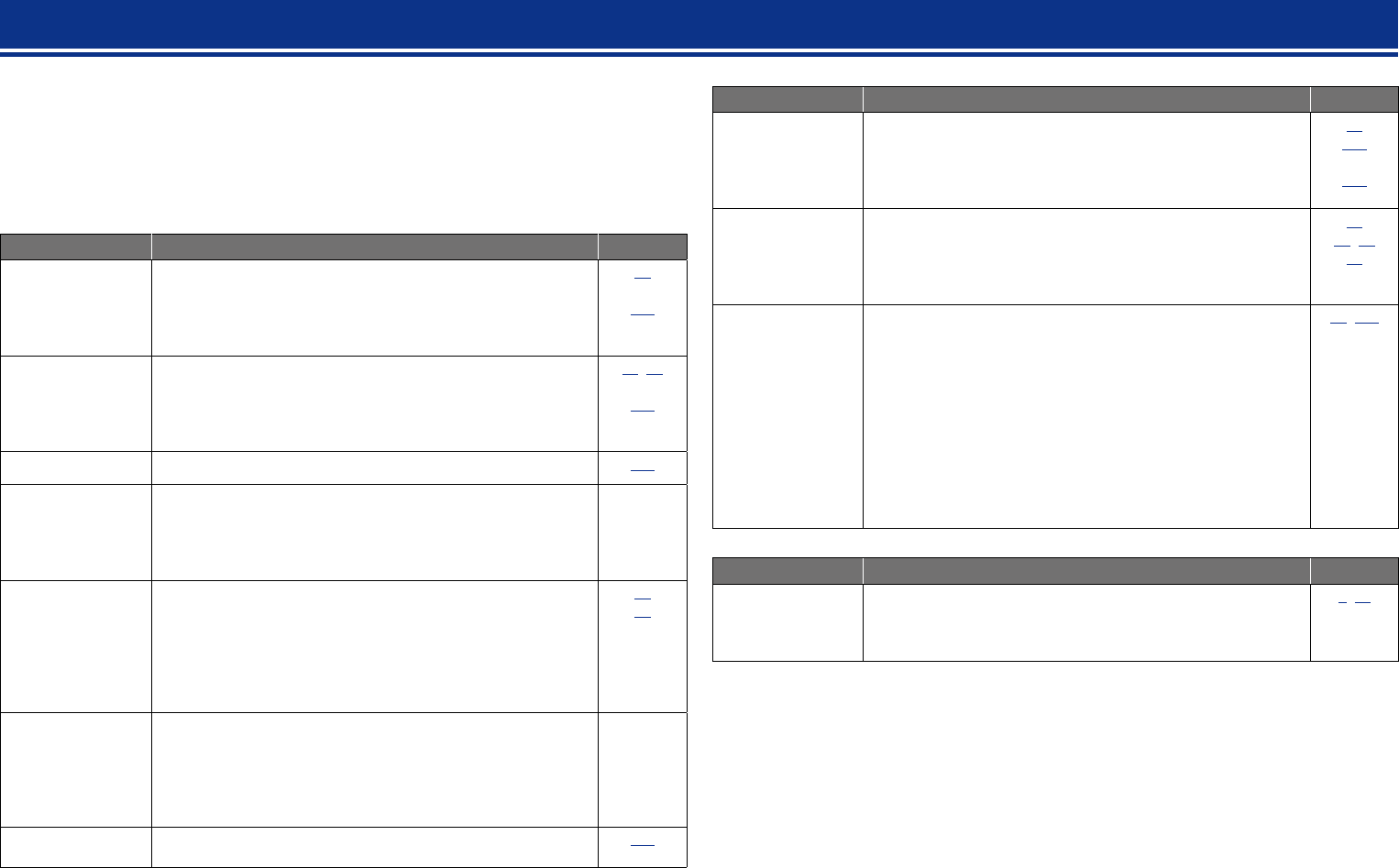
Features
With a discrete-circuit configuration, the power
amplifier provides identical quality for all 7
channels (135 W x 7ch)
The unit is equipped with a power amplifier that reproduces
highfidelity sound in sound mode with equal quality and power for
all channels, true to the original sound.
The power amplifier circuit adopts a discrete-circuit configuration
that achieves high-quality surround sound reproduction.
Supports internet radio, music, and photograph
streaming
Supports AirPlay
®
(vpage69)
You can enjoy a wide variety of content, including listening
to Internet radio, playing the audio files stored on your PC, and
displaying on a TV the photographs stored on your PC.
This unit also supports AirPlay that lets you stream your music
library from an iPhone, iPad, iPod touch or iTunes.
Compatible with “Denon Remote App” for
performing basic operations of the unit with an
iPad, iPhone
z1
or Android smartphone
“Denon Remote App” is application software that allows you to
perform basic operations with an iPad, iPhone, Android smartphone
or Android tablet such as turning the unit ON/OFF, controlling the
volume, and switching the source.
z1 Download “Denon Remote App” from iTunes
®
App Store.
The unit needs to be connected to a LAN and the iPhone/iPod
touch needs to be connected to the same network by Wi-Fi
(wireless LAN).
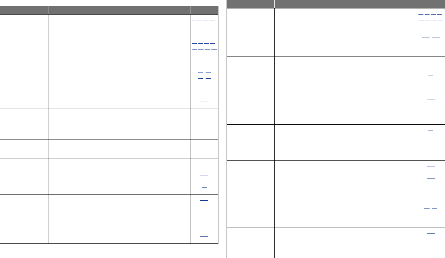
“Setup Assistant”, providing easy-to-follow setup
instructions
First select the language when prompted. Then simply follow the
instructions displayed on the TV screen to set up the speakers,
network, etc.
Easy to use, Graphical User Interface
This unit is equipped with an easy to see “Graphical User Interface”
that uses menu displays and levels. The use of level displays
increases operability of the this unit.
HDMI connectors enable connection to various
digital AV devices (input: 6, output: 2)
The unit is equipped with 6 HDMI input connectors for connecting
devices with HDMI connectors, such as a Blu-ray Disc player,
game machine, HD digital camcorder, etc.
Supports HDMI (3D, ARC, Deep Color, “x.v.Color”,
Auto Lip Sync, 4K) and HDMI control function
(vpage7)
In addition to HDMI 3D and ARC (Audio Return Channel) functions,
this unit supports the video pass-through function, which outputs
video to TV without changing the video quality when video signals
of 4K (3840 × 2160 pixels) are input, and the GUI overlay function,
which overlays the menu screen (GUI) on the 4K video screen.
Simultaneous playback on two HDMI channels
This unit is equipped with two HDMI MONITOR outputs. You can
connect one output to a projector and the other output to a TV for
simultaneous signal outputs.
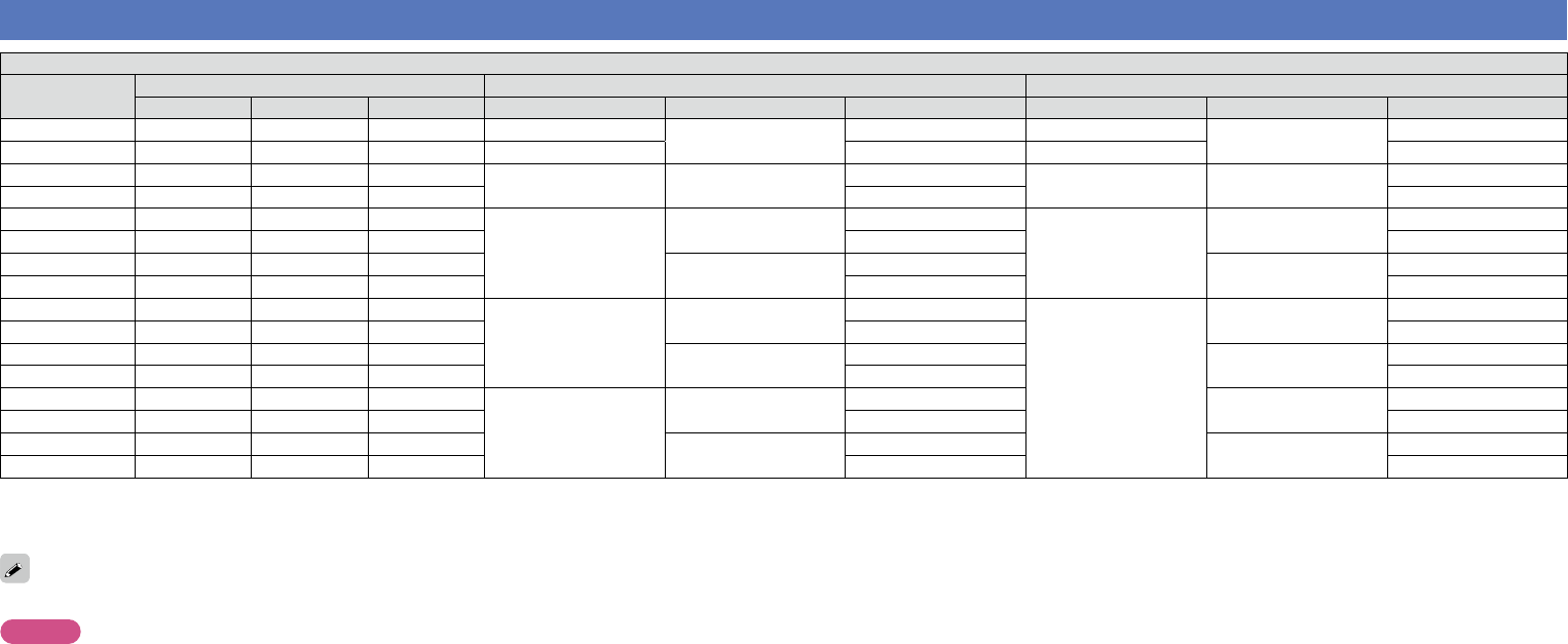
Accessories
Check that the following parts are supplied with the product.
q Getting Started ........................................................................ 1
w CD-ROM (Owner’s manual) ....................................................2
e Safety Instructions ..................................................................1
r Service network list .................................................................1
t Power cord .............................................................................. 1
y Remote control unit (RC-1167) ................................................1
u R03/AAA batteries ...................................................................2
i Setup microphone (ACM1HB) .................................................1
o FM indoor antenna ..................................................................1
yoi
t
Basic version
Advanced version
Informations
v See overleaf
DVD
3
Cautions on handling
•Before turning the power on
Check once again that all connections are correct and that there are
no problems with the connection cables.
•Power is supplied to some of the circuitry even when the unit is
set to the standby mode. When going on vacation or leaving home
for long periods of time, be sure to unplug the power cord from the
power outlet.
•About condensation
If there is a major difference in temperature between the inside of
the unit and the surroundings, condensation (dew) may form on
the operating parts inside the unit, causing the unit not to operate
properly.
If this happens, let the unit sit for an hour or two with the power
turned off and wait until there is little difference in temperature
before using the unit.
•Cautions on using mobile phones
Using a mobile phone near this unit may result in noise. If that
occurs, move the mobile phone away from this unit when it is in use.
•Moving the unit
Turn off the power and unplug the power cord from the power
outlet. Next, disconnect the connection cables to other system units
before moving the unit.
•About care
•Wipe the cabinet and control panel clean with a soft cloth.
•Follow the instructions when using a chemical cleaner.
•Benzene, paint thinner or other organic solvents as well as
insecticide may cause material changes and discoloration if brought
into contact with the unit, and should therefore not be used.
Features
Digital video processor up-scales analog video
signals (SD resolution) to 4K
This unit is equipped with the 4K video upscaling function, which
allows for outputting analog or SD (standard video quality) video
to HDMI at 4K (3840 × 2160 pixels). This enables the unit and a TV
connected with a single HDMI cable and any video source to be
reproduced precisely with HD level of quality.
Direct play for iPod
®
and iPhone
®
via USB
(vpage19)
Music data from an iPod can be played back if you connect the USB
cable supplied with the iPod via the USB port of this unit, and also
an iPod can be controlled with the remote control unit for this unit.
Audyssey DSX
®
This unit is equipped with Audyssey DSX
®
processor. By
connecting front height speakers to this unit and playing back
through Audyssey DSX
®
, you can experience a more powerful
playback expression in the height audio range. By connecting front
wide speakers, you can experience a more powerful playback
expression in the wide audio range.
Basic version
Advanced version
Informations
DVD
Basic version
4
F Connections vpage5
F Setup vpage26
F Playback (Basic operation) vpage33
F Selecting a listening mode (Sound Mode) vpage71
Basic version
Here, we explain the connections and basic operation methods for this unit.
Basic version
Advanced version
Informations
Basic version
DVD
5
Important information
Make connections before using this unit.
To create a home theater that can play back higher quality video and audio by fully utilizing the
capabilities of this unit and your video devices, connect this unit to each of your video devices with
HDMI cables.
nHDMI-compatible device
If your video device does not support HDMI connections, use the following connection.
nHDMI-incompatible device
This unit can change the source that is assigned to the DIGITAL AUDIO IN and COMPONENT VIDEO
IN connectors.
You can change the source for connectors listed in Input connector setting within pages that
describe connections for devices.
For details on assigning a source to connectors, see “Changing the source assigned to connectors”
(vpage12). For the setting method, see “Input Assign” (vpage117).
NOTE
•The menu screen is only displayed on TV connected to this unit via HDMI. If your TV is connected
to this unit via other video output connectors, perform menu operations while seeing the display
on this unit.
•Do not plug in the power cord until all connections have been completed. However, when the “Setup
Assistant” is running, follow the instructions in the “Setup Assistant” (C page 7) screen for making
connections. (During “Setup Assistant” operation, the input/output connectors do not conduct current.)
•When running the “Setup Assistant” (C page 7), turn off the power supply of connected devices.
•When making connections, also refer to the operating instructions of the other devices being connected.
•Be sure to connect the left and right channels properly (left with left, right with right).
•Do not bundle power cords together with connection cables. Doing so can result in noise.
Connections
nHDMI-compatible device
vpage8vpage10vpage10
vpage10vpage10vpage10
vpage10
nHDMI-incompatible device
vpage13vpage14vpage15
vpage16vpage17vpage18
vpage19vpage20vpage21
vpage24
nOthers
vpage80vpage25
Basic version
Advanced version
Informations
Basic version
DVD
6
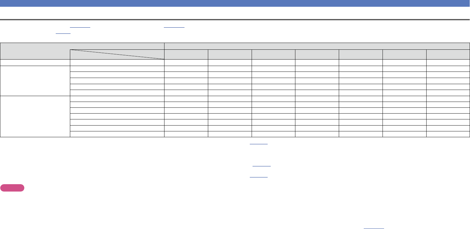
Important information
Converting input video signals for output (Video conversion function)
This unit is equipped with three types of video input connectors (HDMI, Component video and video) and three types of video output connectors
(HDMI, Component video and video).
This function automatically converts various formats of video signals input to this unit into the formats used to output the video signals from
this unit to a monitor.
GFlow of video signals for MAIN ZONEH
HDMI connector
HDMI signalHDMI signal
Component video
signal
Video signalVideo signal
Video connector
HDMI-compatible TV
HDMI-incompatible
TV
HDMI connector
Component video
connectors
Component video
connectors
Component video
connectors
Video connectorVideo connector
HDMI connectorHDMI connector
Video connector
Video device
This unit
Output
Input
(IN)
Output
(MONITOR OUT)
Input
Component video
signal
Component video
connectors
For example, if you connect this unit to an HDMI-compatible TV with a single HDMI cable, this unit automatically converts input signals other
than HDMI video signals to HDMI signals to output from the HDMI connector to the TV. This unit outputs only one type of video signals, so
video signals output from this unit to the TV remain unchanged even if you switch to a device that outputs another type of video signals for
playback. Therefore, you do not need to switch the video input on the TV. Furthermore, this unit converts the input analog video signals such as
video and component video signals to high resolution digital HDMI video signals for output, improving the quality of the video.
If your TV does not support HDMI connections, connect this unit to TV with analog video connectors. This unit can not convert HDMI input
signals to analog video signals, so when inputting from an HDMI device, use component video or video input connectors.
•If you do not want this unit to convert video signals automatically,
use the following setting item to disable this function.
“Video Conversion” (vpage113)
•If you want to change the resolution of video signals output to
the TV, use the following setting item to do so.
“Resolution” (vpage114)
Make Settings as Necessary
•The video conversion function supports the NTSC, PAL, SECAM,
NTSC 4.43, PAL-N, PAL-M and PAL-60 formats.
•Resolutions of HDMI-compatible TVs can be checked at “Video” –
“Monitor” (vpage133).
NOTE
•The menu screen is only displayed on TV connected to this unit
via HDMI. If your TV is connected to this unit via other video
output connectors, perform menu operations while seeing the
display on this unit.
•HDMI signals are digital. HDMI signals cannot be converted into
analog signals.
•When a non-standard video signal from a game machine or some
other source is input, the video conversion function might not
operate.
Basic version
Advanced version
Informations
Basic version
DVD
7
Connecting an HDMI-compatible device
You can connect up to eight HDMI-compatible devices (6-inputs/2-outputs) to the unit.
If the device connected to this unit is equipped with an HDMI connector, it is recommended to use HDMI
connections. Connections with an HDMI cable offer the following benefits that can not be achieved with
other connection methods.
•High quality playback by transmitting audio and video via digital signals
HDMI connections can transmit high definition video and high quality audio formats adopted by Blu-
ray disc players (Dolby Digital Plus, Dolby TrueHD, dts-HD, dts-HD Master Audio).
HDMI connections also convey information required for playback between devices. The information
is used for copyright protection and TV resolution recognition, the ARC function, the HDMI control
function, etc.
•Transmission of audio and video signals with a single HDMI cable
Previous connections require multiple audio and video cables, but HDMI connections require only a
single HDMI cable to transmit audio and video signals. This allows wires in a home theater system,
which tend to be complicated, to be more organized.
•Mutual control through the HDMI control function (vpage91)
This unit and the HDMI device connected via HDMI can be linked to perform operations such as
power control, volume control, and input source switching.
•Other video and audio functions, such as 3D video playback, Content Type, the ARC function,
are supported (vpage11).
•There is more than one version of HDMI standard. The supported functions and the performance vary
according to the version. This unit complies with the HDMI standard, supporting the ARC and 3D playback
functions. To enjoy these functions, the HDMI device connected to this unit also needs to use the same
version of the standard. For the version of the HDMI standard on the device connected to this unit, see
the device’s manual.
•Some TVs do not support audio input via HDMI connections. For details, see your TV’s manual.
nBefore connecting this unit to TV via HDMI connections (vpage8)
nConnecting this unit to a TV via HDMI connections (vpage9)
nConnecting this unit to video devices via HDMI connections (vpage10)
nHDMI function (vpage11)
nSettings related to HDMI connections (vpage11)
Basic version
Advanced version
Informations
Basic version
DVD
8
Connecting an HDMI-compatible device
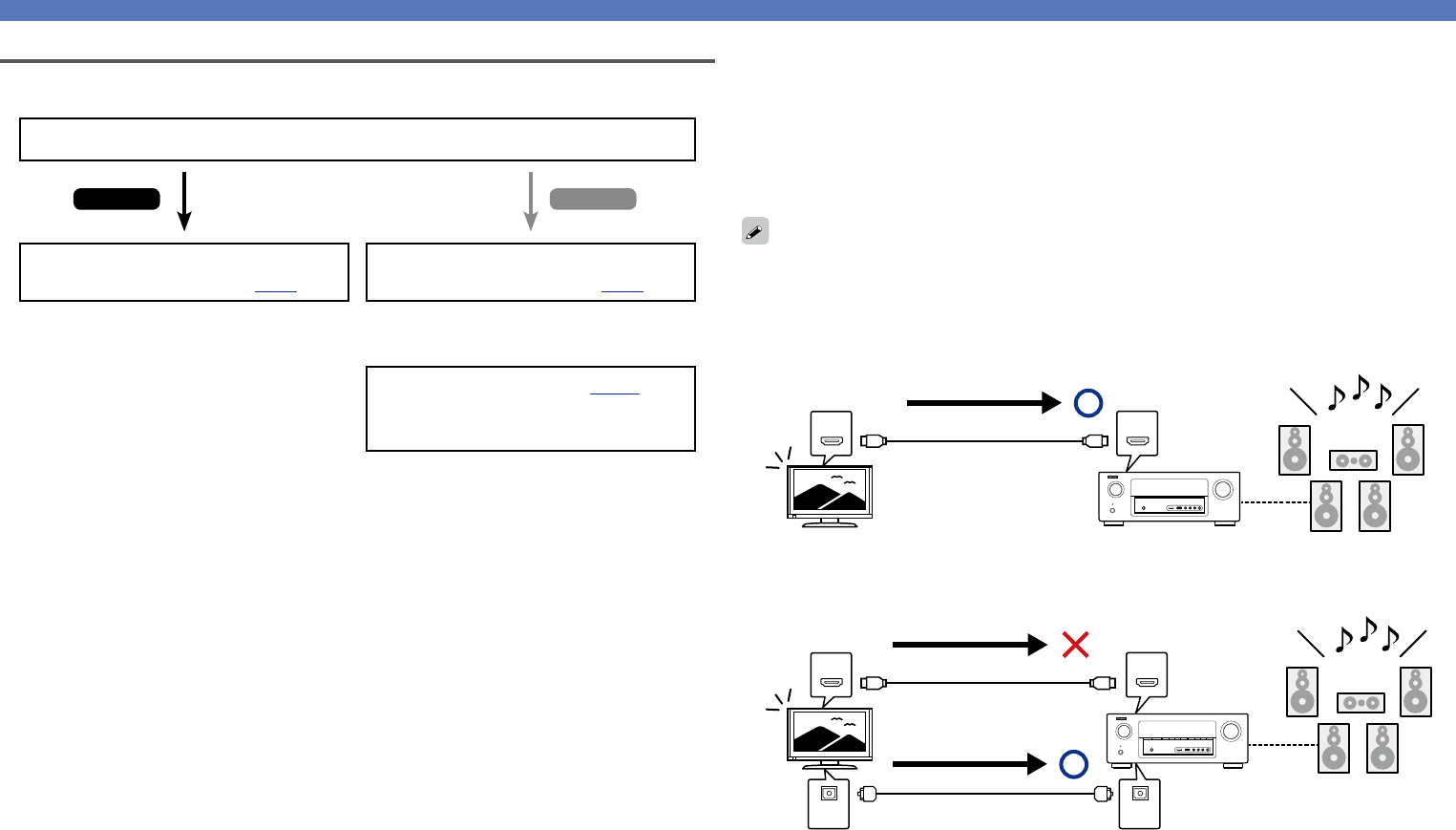
nAbout ARC (Audio Return Channel) function
This function plays TV audio on this unit by sending the TV audio signal to this unit via HDMI cable.
If a TV without the ARC function is connected via HDMI connections, video signals of the playback
device connected to this unit are transmitted to the TV, but this unit can not play back the audio from
the TV. If you want to enjoy surround audio for TV program, a separate audio cable connection is
required.
In contrast, if a TV with the ARC function is connected via HDMI connections, no audio cable connection
is required. Audio signals from the TV can be input to this unit through the HDMI cable between this
unit and the TV. This function allows you to enjoy surround playback on this unit for the TV.
When the ARC function is used, connect a device with a “Standard HDMI cable with Ethernet” or “High
Speed HDMI cable with Ethernet” for HDMI.
Refer to the owner’s manual for your TV for details about TV connection and settings.
GConnection to a TV with the ARC functionH
INOUT
Audio signals from the TV
Audio from the TV
This unitSpeakersTV
GConnection to a TV without the ARC functionH
INOUT
INOUT
Audio signals from the TV
Audio signals from the TV
Optical cable
Audio from the TV
Before connecting this unit to TV via HDMI connections
There are 2 methods to connect HDMI-compatible TV to this unit.
Use the connection method that suits your TV.
Does the TV to be connected to this unit support the ARC function?
Connecting this unit to a TV via
HDMI connections (vpage9)
Connecting this unit to a TV via
HDMI connections (vpage9)
Connecting a TV (vpage13)
For audio connections, use a method other
than HDMI connections.
YesNo
+
Basic version
Advanced version
Informations
Basic version
DVD
9
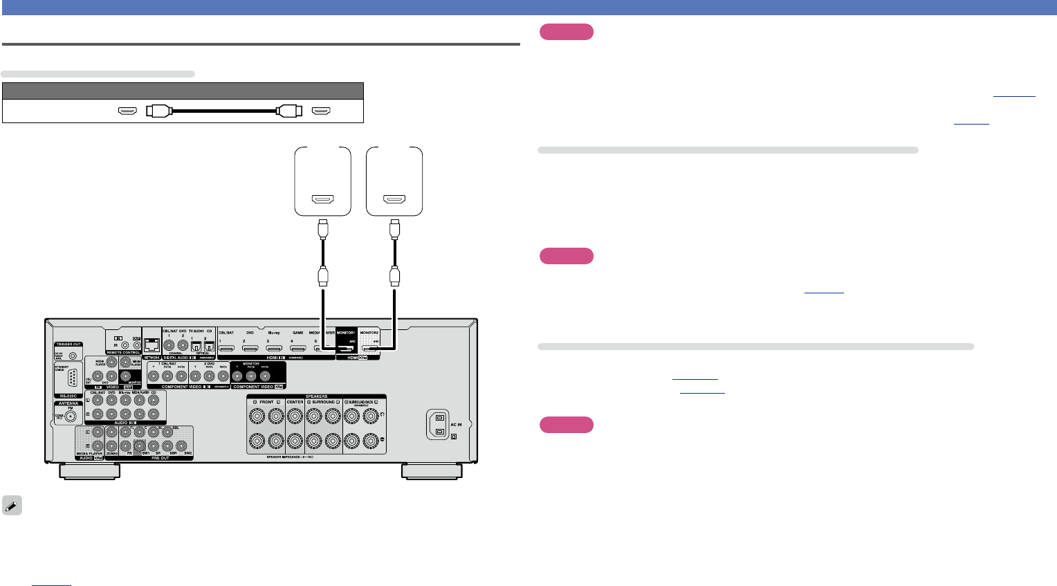
Connecting an HDMI-compatible device
Connecting this unit to a TV via HDMI connections
Cables used for connections
Audio and video cable (sold separately)
HDMI cable
(ARC)
IN
HDMI
(ARC)
IN
HDMI
TV 1TV 2
•Video signals are not output if the input video signals do not match the monitor’s resolution. In this case,
switch the Blu-ray Disc/DVD player’s resolution to a resolution with which the monitor is compatible.
•When this unit and monitor are connected with an HDMI cable, if the monitor is not compatible with
HDMI audio signal playback, only the video signals are output to the monitor. Make audio connections
(vpage13 “Connecting a TV”).
NOTE
•The audio signal from the HDMI output connector (sampling frequency, number of channels, etc.) may be
limited by the HDMI audio specifications of the connected device regarding permissible inputs.
•When connecting a TV that does not support the ARC function, an audio cable connection is
required in addition to the HDMI cable. In this case, refer to “Connecting a TV” (vpage13) for
the connection method.
For the ARC function, see “About ARC (Audio Return Channel) function” (vpage8).
Connecting to a device equipped with a DVI-D connector
The DVI-D (Digital Visual Interface) method is also used for video transmission via digital signals. This is
developed mainly for computers, and some AV devices such as projectors are equipped with this interface.
To output HDMI video signals to a DVI-D video input compatible device, use an HDMI/DVI conversion
cable, which converts HDMI video signals to DVI signals.
The DVI-D connector can transmit high quality digital signals, but the copy guard and other issues may
hinder normal operations for some device combinations.
NOTE
•No sound is output when connected to a device equipped with a DVI-D connector. Make audio
connections as described in “Connecting a TV” (vpage13).
•Signals cannot be output to DVI-D devices that do not support HDCP.
•Depending on the combination of devices, the video signals may not be output.
Settings required when using a TV that supports the ARC function
When using a TV that supports the ARC function, make the following settings.
•Set “HDMI Control” (vpage113) to “On”.
•Set “Control Monitor” (vpage113) to match the number of the HDMI MONITOR connector connected
to the TV that supports the ARC function.
NOTE
If the TV that supports the ARC function is connected to both HDMI MONITOR 1 and HDMI MONITOR 2
connectors, you cannot use ARC function at the same time.
Basic version
Advanced version
Informations
Basic version
DVD
10
Connecting an HDMI-compatible device
OUT
HDMI
GFront panelH
Digital
camcorder
•When this unit is connected to other devices with HDMI cables, connect this unit and TV also with an
HDMI cable.
•When connecting a device that supports Deep Color or 4K, please use a “High Speed HDMI cable” or
“High Speed HDMI cable with Ethernet”.
•Video signals are not output if the input video signals do not match the monitor’s resolution. In this case,
switch the Blu-ray Disc/DVD player’s resolution to a resolution with which the monitor is compatible.
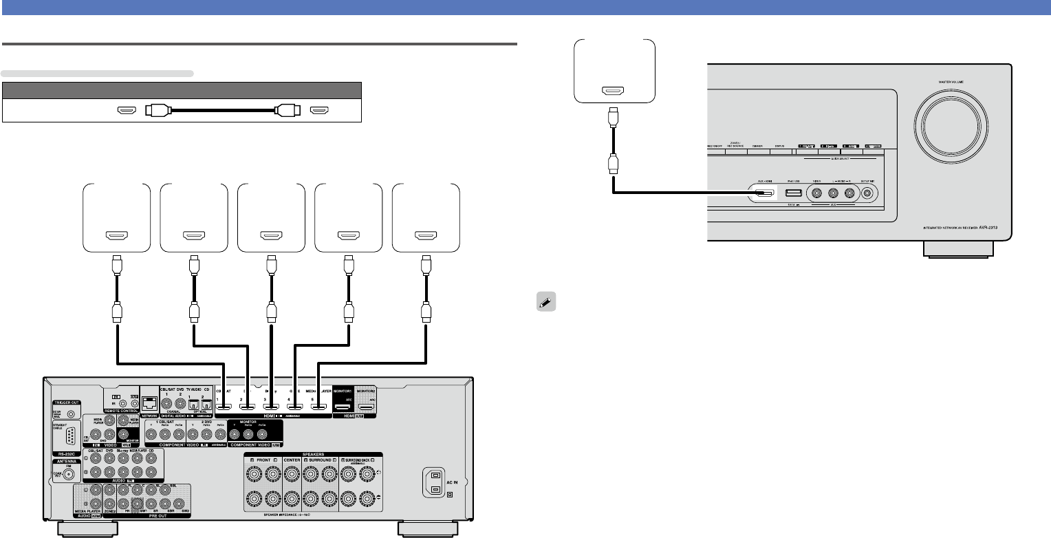
Connecting this unit to video devices via HDMI connections
Cables used for connections
Audio and video cable (sold separately)
HDMI cable
•This interface allows transfer of digital video signals and digital audio signals over a single HDMI cable.
OUT
HDMI
OUT
HDMI
OUT
HDMI
OUT
HDMI
OUT
HDMI
Blu-ray
Disc
player
DVD
player
Media
player
Set-top
box
Game
console
GRear panelH
Basic version
Advanced version
Informations
Basic version
DVD
11
Connecting an HDMI-compatible device
nDeep Color (vpage151)
When a device supporting Deep Color is connected, use a cable compatible with “High Speed HDMI
cable” or “High Speed HDMI cable with Ethernet”.
nAuto Lip Sync (vpage112, 151)
n“x.v.Color”, sYCC601 color, Adobe RGB color, Adobe YCC601 color
(vpage151, 153)
nHigh definition digital audio format
nARC (Audio Return Channel) (vpage8)
Copyright protection system
In order to play back digital video and audio such as BD-Video or DVD-Video via HDMI connection, both
this unit and TV or the player need to support the copyright protection system known as HDCP (High-
bandwidth Digital Content Protection System). HDCP is copyright protection technology comprised of
data encryption and authentication of the connected AV devices. This unit supports HDCP.
•If a device that does not support HDCP is connected, video and audio are not output correctly. Read
the owner’s manual of your television or player for more information.
Settings related to HDMI connections
Set as necessary. For details, see the respective reference pages.
nHDMI Setup (vpage112)
Make settings for HDMI video/audio output.
•Auto Lip Sync•HDMI Control•Power Off Control
•HDMI Audio Out•Standby Source
•Video Output•Control Monitor
NOTE
The audio signal input from the HDMI input connector can be output as an output signal from the HDMI
output connector by setting the HDMI audio output destination to TV.
Audio signals input via the Analog/Coaxial/Optical input connectors cannot be output from the HDMI
MONITOR output connector.
HDMI function
This unit supports the following HDMI functions:
nAbout 3D function
This unit supports input and output of 3D (3 dimensional) video signals of HDMI.
To play back 3D video, you need a TV and player that provide support for the HDMI 3D function and a
pair of 3D glasses.
NOTE
•When playing back 3D video, refer to the instructions provided in the manual of your playback device
together with this manual.
•When playing back 3D video content, the menu screen or status display screen can be superimposed
over the image. However, the menu screen or status display screen cannot be superimposed over
certain 3D video content.
•If 3D video with no 3D information is input, the menu screen and status display on this unit are displayed
over the playback video.
•If 2D video is converted to 3D video on the television, the menu screen and status display on this unit
are not displayed correctly. To view the menu screen and status display on this unit correctly, turn the
television setting that converts 2D video to 3D video off.
nAbout 4K function
This unit supports input and output of 4K (3840 × 2160 pixels) video signals of HDMI.
When a device supporting 4K is connected, use a cable compatible with “High Speed HDMI cable” or
“High Speed HDMI cable with Ethernet”.
nHDMI control function (vpage91)
This function allows you to operate external devices from the unit and operate the unit from external
devices.
NOTE
•The HDMI control function may not work depending on the device it is connected to and its settings.
•You cannot operate a TV or Blu-ray Disc player/DVD player that is not compatible with the HDMI control
function.
nAbout Content Type
This function was added with the HDMI standard. It automatically makes settings suitable for the video-
output type (content information).
NOTE
To enable the Content Type, set “Video Mode” to “Auto” (vpage113).
Basic version
Advanced version
Informations
Basic version
DVD
12
Connecting an HDMI-incompatible device
For high quality video and surround playback, it is recommended to
use an HDMI cable to connect this unit to TV and other video devices
(vpage7 “Connecting an HDMI-compatible device”).
This section describes connections when your device does not
support HDMI connections.
Connection methods for various devices
vpage13vpage14
vpage15vpage16
vpage17
vpage18
vpage19vpage20
vpage21vpage24
Cables used for connections
Video cable (sold separately)
Component video
cable
Video cable
Audio cable (sold separately)
Coaxial digital cable
Optical cable
Audio cable
R
L
R
L
Cable (sold separately)
Ethernet cable
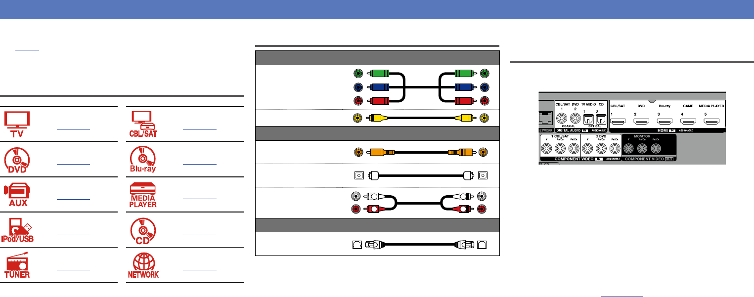
Changing the source assigned to
connectors
This unit can change the source that is assigned to the HDMI IN,
DIGITAL AUDIO IN and COMPONENT VIDEO IN connectors.
Let us take a digital audio connection for Blu-ray Disc players for an
example. The rear panel digital audio input connectors do not have the
input connector indication for Blu-ray disc players (Blu-ray). However,
DIGITAL AUDIO IN connectors have the “ASSIGNABLE” indication,
which means that you can change the source assigned to these
connectors. You can assign Blu-ray disc players to these connectors
to use them for Blu-ray disc players. Select “Blu-ray” when switching
functions on this unit to play back the source connected to these
connectors.
nHow to change the source assigned to
connectors (vpage117)
Basic version
Advanced version
Informations
Basic version
DVD
13
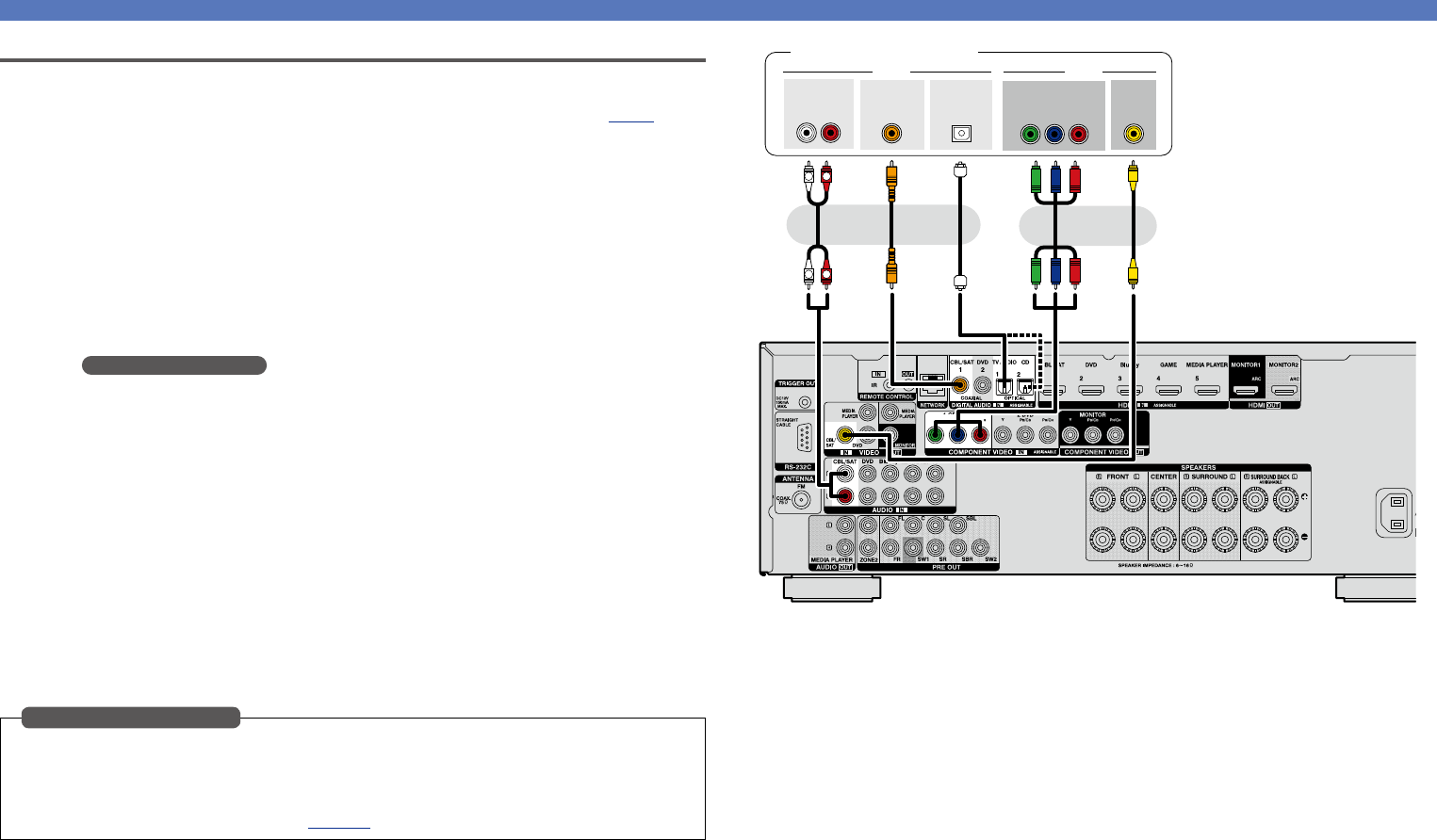
Connecting a TV
•This section describes how to connect when your TV does not support HDMI connections.
For instructions on HDMI connections, see “Connecting an HDMI-compatible device” (vpage7).
•If the TV connected to this unit is equipped with an HDMI connector that supports ARC, digital audio
signals from TV can be transmitted to this unit (vpage 8 “About ARC (Audio Return Channel)
function”). The ARC function allows you to enjoy on this unit the audio from TV programs and HDMI
devices directly connected to TV, without having to make a separate audio connection. For the ARC
function, also see your TV’s manual.
•To listen to TV audio through this device, use the optical digital connection.
For video connections, see “Converting input video signals for output (Video conversion function)”
(vpage6).
nAudio connection
The following methods are available for connecting to this unit. Use either of the methods to make
a connection.
aDIGITAL AUDIO OPTICAL connector
DIGITAL AUDIO COAXIAL connector
z
When a multichannel audio (digital bit stream audio) is input, this unit decodes the audio to play
back surround sound.
z When making this type of connection, you must change the settings on this unit.
(v Input connector setting )
nVideo connection
The following methods are available for connecting to this unit. Use either of the methods to make
a connection.
The numbers prefixed with connectors indicate the recommendation order. The smaller the number is,
the higher playback quality is achieved.
aCOMPONENT VIDEO OUT (MONITOR) connector
This makes an analog video connection. This connection method separates video signals into 3
signals for transmission based on color components, achieving the best quality video playback
among analog video connections, with less signal degradation.
sVIDEO OUT (MONITOR) connector
This makes an analog video connection.
When making the following connection, you must change the input connector settings.
aDIGITAL AUDIO COAXIAL connector
When connecting to connectors marked as 1, change “CBL/SAT” to “TV AUDIO”.
For how to change, see “Input Assign” (vpage117).
Input connector setting
aas
a
VIDEOAUDIO
IN
VIDEO
OUT
COAXIAL
OPTICAL
OUT
COMPONENT VIDEO
YP
BPR
IN
TV
oror
NOTE
•The menu screen is only displayed on TV connected to this unit via HDMI. If your TV is connected
to this unit via other video output connectors, perform menu operations while seeing the display
on this unit.
•If you do not connect this unit to your TV via HDMI, do not make HDMI connections for video inputs from
other video devices, either. For details see “Converting input video signals for output (Video conversion
function)” (vpage6).
Connecting an HDMI-incompatible device
Basic version
Advanced version
Informations
Basic version
DVD
14
aaass
R
L
R
L
VIDEOAUDIO
AUDIO
RL
OUT
OUT
VIDEO
COMPONENT VIDEO
YP
BPR
OUT
OUT
COAXIAL
OPTICAL
OUT
Satellite tuner/Cable TV
ororor
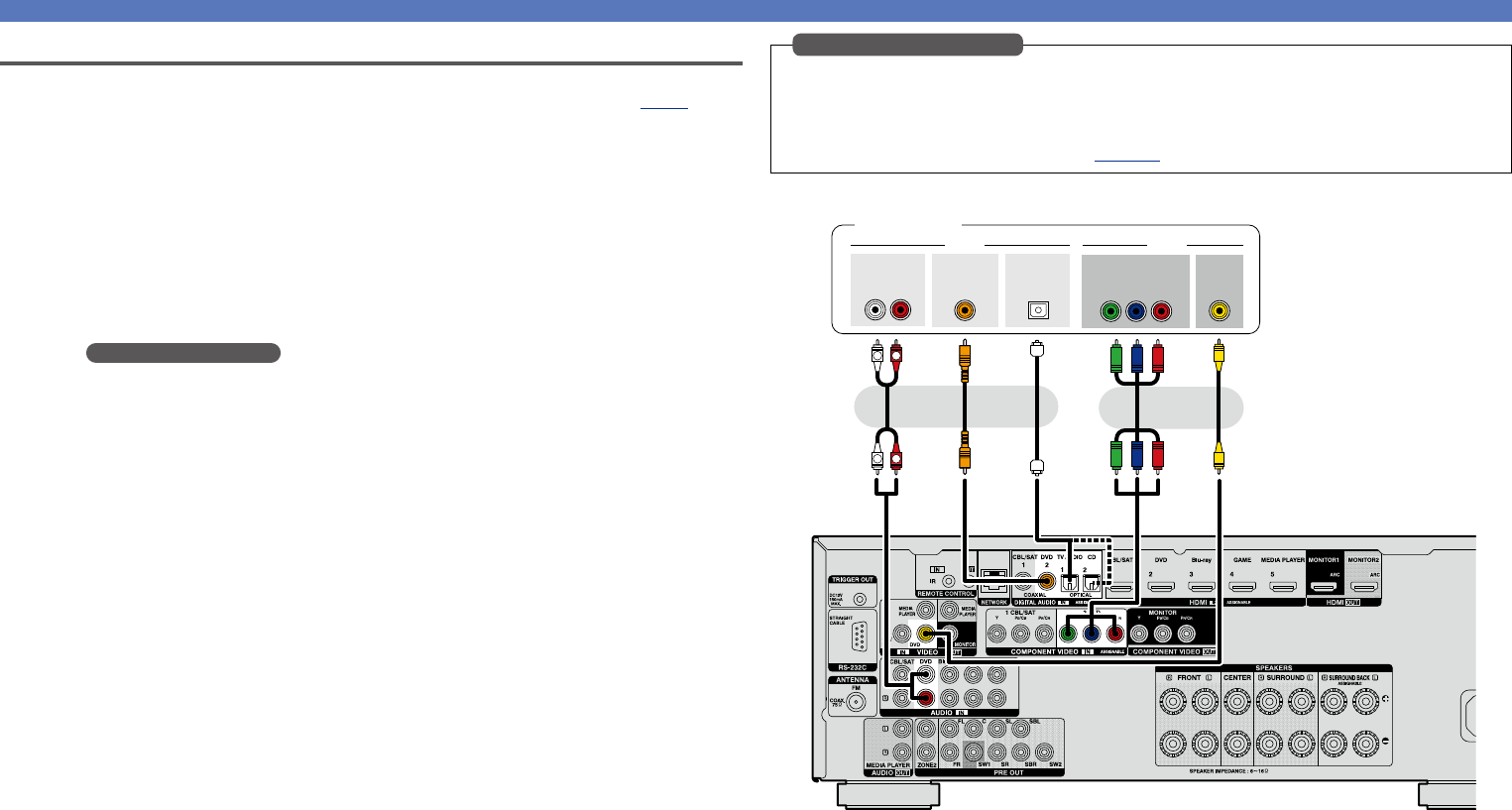
Connecting a set-top box (Satellite tuner/cable TV)
This section describes how to connect when your satellite tuner or cable TV does not support HDMI
connections.
For instructions on HDMI connections, see “Connecting an HDMI-compatible device” (vpage7).
nAudio connection
The following methods are available for connecting to this unit. Use either of the methods to make
a connection.
The numbers prefixed with connectors indicate the recommendation order. The smaller the number is,
the higher playback quality is achieved.
aDIGITAL AUDIO COAXIAL connector
DIGITAL AUDIO OPTICAL connector
z
When a multichannel audio (digital bit stream audio) is input, this unit decodes the audio to play
back surround sound.
zWhen making this type of connection, you must change the settings on this unit.
(v Input connector setting )
sAUDIO IN (CBL/SAT) connector
This makes an analog audio connection. This type of connection converts digital audio to analog
audio, so the output audio may be degraded compared to connections a.
nVideo connection
The following methods are available for connecting to this unit. Use either of the methods to make
a connection.
The numbers prefixed with connectors indicate the recommendation order. The smaller the number is,
the higher playback quality is achieved.
aCOMPONENT VIDEO IN (CBL/SAT) connector
This makes an analog video connection. This connection method separates video signals into 3
signals for transmission based on color components, achieving the best quality video playback
among analog video connections, with less signal degradation.
sVIDEO IN (CBL/SAT) connector
This makes an analog video connection.
When making the following connection, you must change the input connector settings.
aDIGITAL AUDIO OPTICAL connector
When connecting to connectors marked as 1, change “TV AUDIO” to “CBL/SAT”.
For how to change, see “Input Assign” (vpage117).
Input connector setting
Connecting an HDMI-incompatible device
Basic version
Advanced version
Informations
Basic version
DVD
15
Connecting an HDMI-incompatible device
Connecting a DVD player
This section describes how to connect when your DVD player does not support HDMI connections.
For instructions on HDMI connections, see “Connecting an HDMI-compatible device” (vpage7).
nAudio connection
The following methods are available for connecting to this unit. Use either of the methods to make
a connection.
The numbers prefixed with connectors indicate the recommendation order. The smaller the number is,
the higher playback quality is achieved.
aDIGITAL AUDIO COAXIAL connector
DIGITAL AUDIO OPTICAL connector
z
When a multichannel audio (digital bit stream audio) is input, this unit decodes the audio to play
back surround sound.
zWhen making this type of connection, you must change the settings on this unit.
(v Input connector setting )
sAUDIO IN (DVD) connector
This makes an analog audio connection. This type of connection converts digital audio to analog
audio, so the output audio may be degraded compared to connections a.
nVideo connection
The following methods are available for connecting to this unit. Use either of the methods to make
a connection.
The numbers prefixed with connectors indicate the recommendation order. The smaller the number is,
the higher playback quality is achieved.
aCOMPONENT VIDEO IN (DVD) connector
This makes an analog video connection. This connection method separates video signals into 3
signals for transmission based on color components, achieving the best quality video playback
among analog video connections, with less signal degradation.
sVIDEO IN (DVD) connector
This makes an analog video connection.
When making the following connection, you must change the input connector settings.
aDIGITAL AUDIO OPTICAL connector
When connecting to connectors marked as 1, change “TV AUDIO” to “DVD”.
For how to change, see “Input Assign” (vpage117).
Input connector setting
aaass
R
L
R
L
VIDEOAUDIO
AUDIO
RL
OUT
OUT
VIDEO
COMPONENT VIDEO
YP
BPR
OUT
OUT
COAXIAL
OPTICAL
OUT
DVD player
ororor
Basic version
Advanced version
Informations
Basic version
DVD
16
Connecting an HDMI-incompatible device
Connecting a Blu-ray Disc player
This section describes how to connect when your Blu-ray disc player does not support HDMI connections.
For instructions on HDMI connections, see “Connecting an HDMI-compatible device” (vpage7).
nAudio connection
The following methods are available for connecting to this unit. Use either of the methods to make
a connection.
The numbers prefixed with connectors indicate the recommendation order. The smaller the number is,
the higher playback quality is achieved.
aDIGITAL AUDIO COAXIAL connector
DIGITAL AUDIO OPTICAL connector
When a multichannel audio (digital bit stream audio) is input, this unit decodes the audio to play
back surround sound. However, digital bit stream audio signals for HD audios from Blu-ray disc
players (such as Dolby Digital Plus and dts-HD) can not be transmitted.
When making this type of connection, you must change the settings on this unit.
(v Input connector setting )
sAUDIO IN (Blu-ray) connector
This makes an analog audio connection. This type of connection converts digital audio to analog
audio, so the output audio may be degraded compared to connections a.
nVideo connection
The following methods are available for connecting to this unit.
aCOMPONENT VIDEO IN connector
This makes an analog video connection. This connection method separates video signals into 3
signals for transmission based on color components, achieving the best quality video playback
among analog video connections, with less signal degradation.
When making this type of connection, you must change the settings on this unit.
(v Input connector setting )
When making the following connection, you must change the input connector settings.
aDIGITAL AUDIO COAXIAL connector
When connecting to connectors marked as 1, change “CBL/SAT” to “Blu-ray”.
DIGITAL AUDIO OPTICAL connector
When connecting to connectors marked as 1, change “TV AUDIO” to “Blu-ray”.
aCOMPONENT VIDEO IN connector
When connecting to connectors marked as 1, change “CBL/SAT” to “Blu-ray”.
For how to change, see “Input Assign” (vpage117).
Input connector setting
aaas
R
L
R
L
VIDEOAUDIO
AUDIO
RL
OUT
COMPONENT VIDEO
YP
BPR
OUT
OUT
COAXIAL
OPTICAL
OUT
Blu-ray Disc player
oror
When you want to play back HD Audio (Dolby TrueHD, DTS-HD, Dolby Digital Plus, DTS Express) and Multi-
channel PCM with this unit, use an HDMI connection (vpage7 “Connecting an HDMI-compatible
device”).
Basic version
Advanced version
Informations
Basic version
DVD
17
Connecting an HDMI-incompatible device
Connecting a digital camcorder
This section describes how to connect when your digital camcorder does not support HDMI connections.
For instructions on HDMI connections, see “Connecting an HDMI-compatible device” (vpage7).
nAudio connection
The following methods are available for connecting to this unit. Use either of the methods to make
a connection.
The numbers prefixed with connectors indicate the recommendation order. The smaller the number is,
the higher playback quality is achieved.
aDIGITAL AUDIO COAXIAL connector
DIGITAL AUDIO OPTICAL connector
When a multichannel audio (digital bit stream audio) is input, this unit decodes the audio to play
back surround sound.
When making this type of connection, you must change the settings on this unit.
(v Input connector setting )
sAUDIO IN (AUX) connector
This makes an analog audio connection. This type of connection converts digital audio to analog
audio, so the output audio may be degraded compared to connections a.
nVideo connection
The following methods are available for connecting to this unit. Use either of the methods to make
a connection.
The numbers prefixed with connectors indicate the recommendation order. The smaller the number is,
the higher playback quality is achieved.
aCOMPONENT VIDEO IN connector
This makes an analog video connection. This connection method separates video signals into 3
signals for transmission based on color components, achieving the best quality video playback
among analog video connections, with less signal degradation.
When making this type of connection, you must change the settings on this unit.
(v Input connector setting )
sVIDEO IN (AUX) connector
This makes an analog video connection.
When making the following connection, you must change the input connector settings.
aDIGITAL AUDIO COAXIAL connector
When connecting to connectors marked as 1, change “CBL/SAT” to “AUX”.
DIGITAL AUDIO OPTICAL connector
When connecting to connectors marked as 1, change “TV AUDIO” to “AUX”.
aCOMPONENT VIDEO IN connector
When connecting to connectors marked as 1, change “CBL/SAT” to “AUX”.
For how to change, see “Input Assign” (vpage117).
Input connector setting
R
L
R
L
OUT
AUDIOVIDEO
VIDEO
AUDIO
RL
OUT
ss
Digital camcorder
GFront panelH
aaa
VIDEOAUDIO
COMPONENT VIDEO
YP
BPR
OUT
OUT
COAXIAL
OPTICAL
OUT
Digital camcorder
GRear panelH
or
You can enjoy games by connecting a game machine via the AUX input connector. In this case, select the
input source to “AUX”.
NOTE
When a non-standard video signal from a game machine or some other source is input, the video conversion
function (vpage6) might not operate. In this case, use the monitor output of the same connector
as the input.
Basic version
Advanced version
Informations
Basic version
DVD
18
Connecting an HDMI-incompatible device
Connecting a media player
•This section describes how to connect when your media player does not support HDMI connections.
For instructions on HDMI connections, see “Connecting an HDMI-compatible device” (vpage7).
•When recording analog audio, use the analog connection. See “REC OUT mode” (vpage94) for
operating instructions.
nAudio connection
The following methods are available for connecting to this unit. Use either of the methods to make
a connection.
The numbers prefixed with connectors indicate the recommendation order. The smaller the number is,
the higher playback quality is achieved.
aDIGITAL AUDIO COAXIAL connector
DIGITAL AUDIO OPTICAL connector
When a multichannel audio (digital bit stream audio) is input, this unit decodes the audio to play
back surround sound.
When making this type of connection, you must change the settings on this unit.
(v Input connector setting )
sAUDIO IN/OUT (MEDIA PLAYER) connector
This makes an analog audio connection. This type of connection converts digital audio to analog
audio, so the output audio may be degraded compared to connections a.
nVideo connection
The following methods are available for connecting to this unit. Use either of the methods to make
a connection.
The numbers prefixed with connectors indicate the recommendation order. The smaller the number is,
the higher playback quality is achieved.
aCOMPONENT VIDEO IN connector
This makes an analog video connection. This connection method separates video signals into 3
signals for transmission based on color components, achieving the best quality video playback
among analog video connections, with less signal degradation.
When making this type of connection, you must change the settings on this unit.
(v Input connector setting )
sVIDEO IN/OUT (MEDIA PLAYER) connector
This makes an analog video connection.
When making the following connection, you must change the input connector settings.
aDIGITAL AUDIO COAXIAL connector
When connecting to connectors marked as 1, change “CBL/SAT” to “MEDIA PLAYER”.
DIGITAL AUDIO OPTICAL connector
When connecting to connectors marked as 1, change “TV AUDIO” to “MEDIA PLAYER”.
aCOMPONENT VIDEO IN connector
When connecting to connectors marked as 1, change “CBL/SAT” to “MEDIA PLAYER”.
For how to change, see “Input Assign” (vpage117).
Input connector setting
aaassss
R
L
R
L
R
L
R
L
VIDEOVIDEOAUDIOAUDIO
AUDIO
RL
OUT
COMPONENT VIDEO
YP
BPR
OUT
OUT
COAXIAL
AUDIO
RL
IN
OPTICAL
OUT
OUT
VIDEO
IN
VIDEO
Media player
ororor
NOTE
To record video signals through this unit, use the video cable for connection between this unit and the
player.
Basic version
Advanced version
Informations
Basic version
DVD
19
Connecting an iPod or USB memory device to the iPod/USB port
•You can enjoy music stored on an iPod or USB memory device.
•For operating instructions see “Playing an iPod” (vpage35) or “Playing a USB memory device”
(vpage38).
Cables used for connections
To connect an iPod to this unit, use the USB cable supplied with the iPod.
USB memory
device
iPod
or
DENON does not guarantee that all USB memory devices will operate or receive power. When using a
portable USB connection type HDD of the kind to which an AC adapter can be connected to supply power,
use the AC adapter.
NOTE
•USB memory devices will not work via a USB hub.
•It is not possible to use this unit by connecting the unit’s iPod/USB port to a PC via a USB cable.
•Do not use an extension cable when connecting a USB memory device. This may cause radio interference
with other devices.
•When connecting an iPhone to this unit, keep the iPhone at least 20 cm away from this unit. If the iPhone
is kept closer to this unit and a telephone call is received by the iPhone, noise may be output from this
device.
•If the iPod is connected using an iPod cable (commercially available) that is longer than 2 m, sound may
not be played correctly. In this case, use a genuine iPod cable, or a cable that is shorter than 1 m.
Connecting an HDMI-incompatible device
Supported iPod models
•iPod classic
•iPod nano
•iPod touch
•iPhone
(as of May 2012)
Basic version
Advanced version
Informations
Basic version
DVD
20
Connecting an HDMI-incompatible device
Connecting a CD player
You can enjoy CD sound.
nAudio connection
The following methods are available for connecting to this unit. Use either of the methods to make
a connection.
The numbers prefixed with connectors indicate the recommendation order. The smaller the number is,
the higher playback quality is achieved.
aDIGITAL AUDIO COAXIAL connector
z
DIGITAL AUDIO OPTICAL connector
When a multichannel audio (digital bit stream audio) is input, this unit decodes the audio to play
back surround sound.
zWhen making this type of connection, you must change the settings on this unit.
(v Input connector setting )
sAUDIO IN (CD) connector
This makes an analog audio connection. This type of connection converts digital audio to analog
audio, so the output audio may be degraded compared to connections a.
When making the following connection, you must change the input connector settings.
aDIGITAL AUDIO COAXIAL connector
When connecting to connectors marked as 1, change “CBL/SAT” to “CD”.
For how to change, see “Input Assign” (vpage117).
Input connector setting
aas
R
L
R
L
AUDIO
AUDIO
RL
OUT
OUT
COAXIAL
OPTICAL
OUT
CD player
oror
Basic version
Advanced version
Informations
Basic version
DVD
21
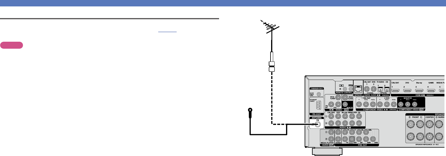
Connecting an FM antenna
•Connect the FM antenna supplied with the unit to enjoy listening to radio broadcasts.
•After connecting the antenna and receiving a broadcast signal (vpage41 “Listening to FM
broadcasts”), fix the antenna with tape in a position where the noise level becomes minimal.
NOTE
•Do not connect two FM antennas simultaneously.
•If you are unable to receive a good broadcast signal, we recommend installing an outdoor antenna. For
details, inquire at the retail store where you purchased the unit.
Connecting an HDMI-incompatible device
FM outdoor
antenna
Direction of broadcasting station
75 Ω coaxial
cable
FM indoor antenna
(supplied)
Basic version
Advanced version
Informations
Basic version
DVD
22
Connecting an external power amplifier
•You can use this unit as a pre-amp by connecting a commercially available power amp to the PRE OUT
connector. Adding a power amp to each of the channels provides an even greater sound presence.
•Select the terminal to use and connect the device.
•When using just one surround back speaker, connect it to the left channel (L) terminal.
•Use the volume control on the subwoofer to control subwoofer volume.
•If the subwoofer volume sounds low, use the volume control provided on the subwoofer to adjust the
volume.
L
L
L
L
L
L
RRR
RRR
CENTERSURROUND
BACK
RL
SURROUND
RL
FRONT
RL
AUDIO
SUB-
WOOFER
2
AUDIO
SUB-
WOOFER
1
AUDIO
Power amplifier
Subwoofer
(Primary)
Subwoofer
(Secondary)
Basic version
Advanced version
Informations
Basic version
DVD
23
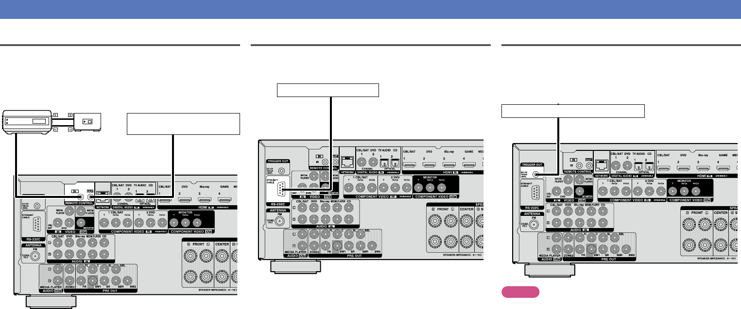
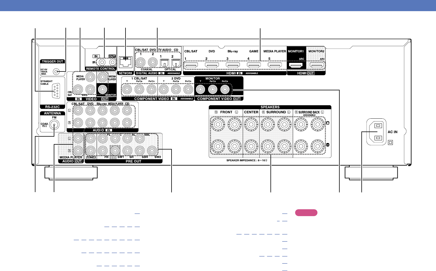
Connecting an external control device
REMOTE CONTROL jacks
If this unit is installed in a location that is out of range of the signal
from the remote control unit, you can still operate the unit and the
devices connected to it by using a commercially available IR receiver.
You can also use it to remotely control ZONE2 (another room).
AUX
OUT
Device equipped with a
REMOTE CONTROL IN jack
Infrared
retransmitter
Infrared
sensor
Output
Input
RS-232C connector
When you connect an external control device, you can control this
unit with the external control device (such as power supply operation,
volume adjustment, and input source switching).
External serial controller
Perform the operation below beforehand.
q Turn on the power of this unit.
w Turn off the power of this unit from the external controller.
e Check that the unit is in the standby mode.
TRIGGER OUT jack
When a device with TRIGGER IN jack is connected, the connected
device’s power on/standby can be controlled through linked operation
to this unit.
The TRIGGER OUT jack outputs a maximum 12 V/150 mA electrical
signal.
12 V/150 mA trigger-compatible device
NOTE
•Use the monaural mini-plug cable for connecting TRIGGER OUT
jacks. Do not use the stereo mini-plug cable.
•If the permissible trigger input level for the connected device is larger
than 12 V/150 mA, or has shorted, the TRIGGER OUT jack cannot be
used. In this case, turn off the power to the unit, and disconnect it.
Basic version
Advanced version
Informations
Basic version
DVD
24
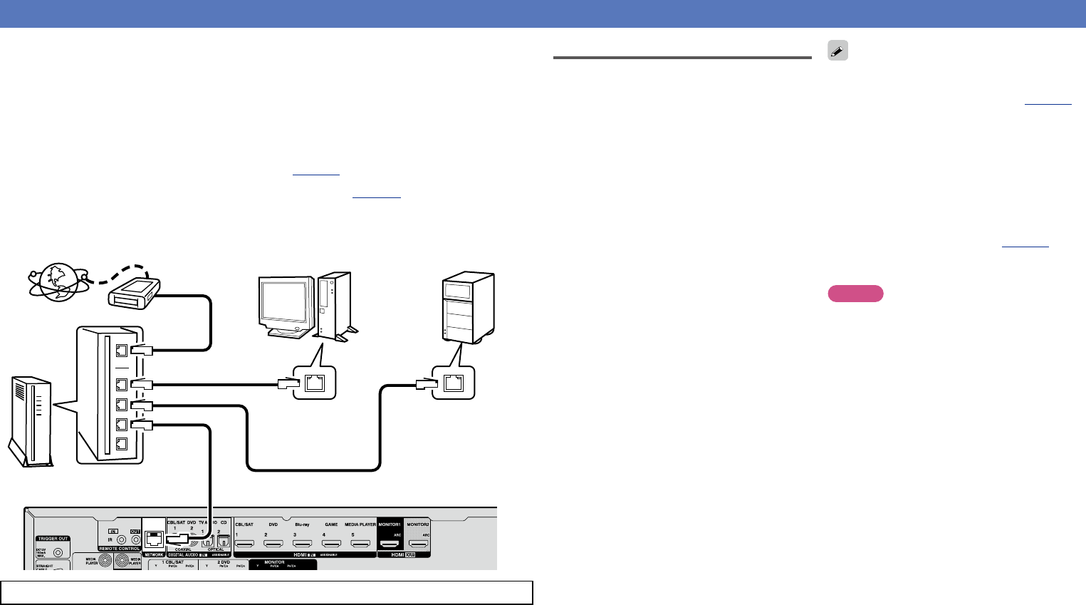
Connecting to a home network (LAN)
You can connect this unit to your home network (LAN) to perform various types of playbacks and operations
as follows. Make network connections for this unit by carefully reading information on this page.
•Playback of network audio such as the Internet radio and music servers
•Playback of music from online services
•AirPlay
•Operations on this unit via the network
In addition, when an updated firmware becomes available for improving this unit, the update information is
delivered from us to this unit over the network. You can then download the latest firmware.
For more information, on the menu, select “Update” (vpage134).
Network settings are necessary. See “Network” on the menu (vpage126) for more information on
network setting.
Internet
To WAN side
Router
To LAN port
To LAN port
LAN port/
Ethernet
connector
LAN port/
Ethernet
connector
PC
NAS
(Network Attached
Storage)
Modem
For connections to the Internet, contact an ISP (Internet Service Provider) or a computer shop.
Required system
nBroadband internet connection
nModem
Device that connects to the broadband circuit
and conducts communications on the Internet.
A type that is integrated with a router is also
available.
nRouter
When using this unit, we recommend you use
a router equipped with the following functions:
•Built-in DHCP server
This function automatically assigns IP
addresses on the LAN.
•Built-in 100BASE-TX switch
When connecting multiple devices, we
recommend a switching hub with a speed of
100 Mbps or greater.
nEthernet cable
(CAT-5 or greater recommended)
•Use only a shielded STP or ScTP LAN cable
which is available at retailer.
•The normal shielded-type Ethernet cable
is recommended. If a flat-type cable or
unshielded-type cable is used, other devices
could be affected by noise.
•If you have an Internet provider contract for a line
on which network settings are made manually,
make the settings at “Network” (vpage126).
•With this unit, it is possible to use the DHCP and
Auto IP functions to make the network settings
automatically.
•When using this unit with the broadband router’s
DHCP function enabled, this unit automatically
performs the IP address setting and other
settings.
When using this unit connected to a network with
no DHCP function, make the settings for the IP
address, etc., at “Network” (vpage126).
•When setting manually, check the setting
contents with the network administrator.
NOTE
•A contract with an ISP is required to connect to
the Internet.
No additional contract is needed if you already
have a broadband connection to the Internet.
•The types of routers that can be used depend on
the ISP. Contact an ISP or a computer shop for
details.
•DENON assumes no responsibility whatsoever
for any communication errors or troubles
resulting from customer’s network environment
or connected devices.
•This unit is not compatible with PPPoE. A PPPoE-
compatible router is required if you have a contract
for a type of line set by PPPoE.
•Do not connect an NETWORK connector directly
to the LAN port/ Ethernet connector on your
computer.
•To listen to audio streaming, use a router that
supports audio streaming.
Basic version
Advanced version
Informations
Basic version
DVD
25
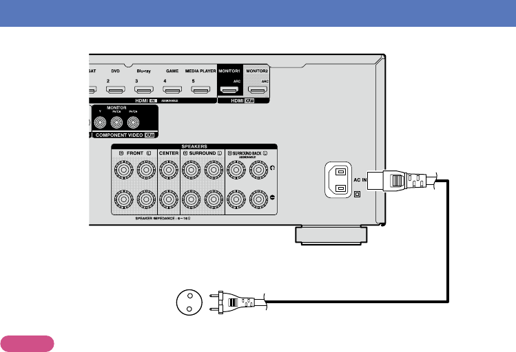
Connecting the power cord
After completing all the connections, insert the power plug into the power outlet.
To household power outlet
(AC 230 V, 50/60 Hz)
Power cord (supplied)
NOTE
•Do not plug in the power cord until all connections have been completed.
•Do not bundle power cords together with connection cables. Doing so can result in humming or noise.
Basic version
Advanced version
Informations
Basic version
DVD
26
The acoustic characteristics of the connected speakers and
listening room are measured and the optimum settings are made
automatically. This is called “Audyssey
®
Setup”.
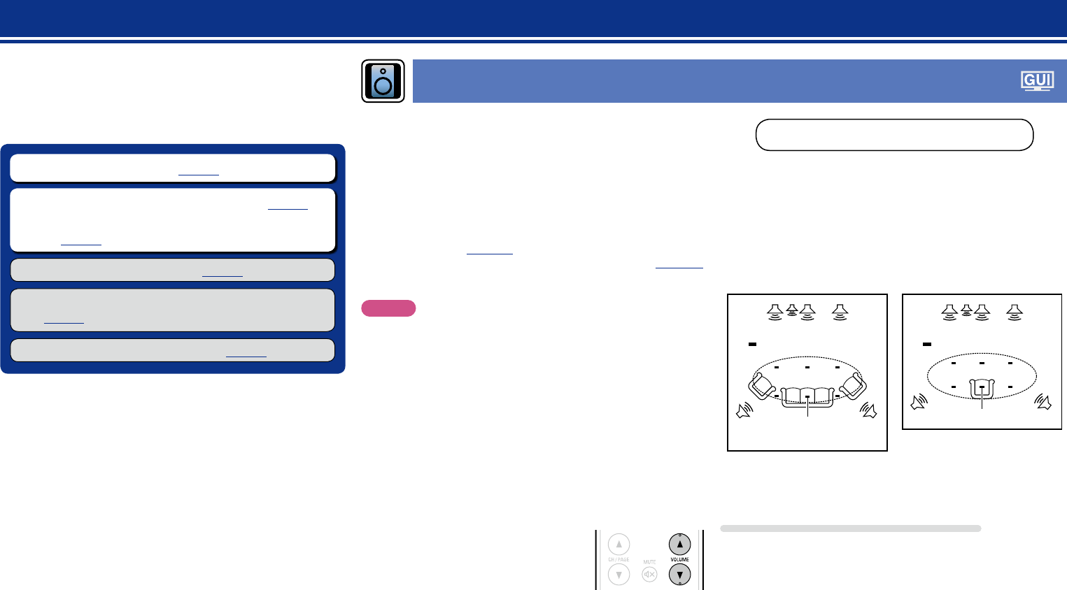
To perform measurement, place the setup microphone in
multiple locations all around the listening area. For best results,
we recommend you measure in six or more positions, as shown
in the illustration (up to eight positions).
•When performing Audyssey
®
Setup, Audyssey MultEQ
®
XT/
Audyssey Dynamic EQ
®
/Audyssey Dynamic Volume
®
functions
become active (vpage108).
•To set up the speakers manually, use “Speakers” (vpage121)
on the menu.
NOTE
•Make the room as quiet as possible. Background noise can disrupt
the room measurements. Close windows and turn off the power on
electronic devices (TVs, radios, air conditioners, fluorescent lights,
etc.). The measurements could be affected by the sounds emitted
by such devices.
•During the measurement process, place cell phones outside the
listening room. Cell phone signals could disrupt the measurements.
•Do not unplug the setup microphone from the main unit until
Audyssey
®
Setup is completed.
•Do not stand between the speakers and setup microphone or allow
obstacles in the path while the measurements are being made. This
will cause inaccurate readings.
•During the measurement process, loud test sounds may be played,
but this is part of normal operation. If there is background noise in
room, these test signals will increase in volume.
•Operating
VOLUME df on the remote
control unit or MASTER VOLUME on the
main unit during the measurements will
cancel the measurements.
•Measurement cannot be performed when headphones are
connected. Unplug the headphones before performing Audyssey
®
Setup.
Setup
Here, we explain “Audyssey
®
Setup”, which allows you to
automatically make the optimal settings for your speakers, and
“Network”, which allows you to connect this unit to a home network
(LAN).
This unit lets you play via your home network (LAN) music files stored
on a computer and music content such as that from Internet radio.
nSpeaker connection (vpage80)
nSet up speakers (Audyssey
®
Setup) (vpage26)
nMaking the network settings (Network)
(vpage32)
Playback (Basic operation) (vpage33)
Selecting a listening mode (Sound Mode)
(vpage71)
Playback (Advanced operation) (vpage91)
Set up speakers (Audyssey
®
Setup)
About setup microphone placement
•Measurements are performed by placing the setup microphone
successively at multiple positions throughout the entire listening
area, as shown in GExampleqH. For best results, we recommend
you measure in six or more positions, as shown in the illustration (up
to eight positions).
•Even if the listening environment is small as shown in GExamplewH,
measuring at multiple points throughout the listening environment
results in more effective correction.
FLSWCFR
SRSL
*
M
FLSWCFR
SRSL
*
M
(
: Measuring positions)
GExampleqHGExamplewH
(
: Measuring positions)
FLFront speaker (L)SWSubwoofer
FRFront speaker (R)SLSurround speaker (L)
CCenter speakerSRSurround speaker (R)
About the main listening position (*M)
The main listening position is the position where listeners would
normally sit or where one would normally sit alone within the listening
environment. Before starting Audyssey
®
Setup, place the setup
microphone in the main listening position. Audyssey MultEQ
®
XT uses
the measurements from this position to calculate speaker distance,
level, polarity, and the optimum crossover value for the subwoofer.
Basic version
Advanced version
Informations
Basic version
v See overleaf
DVD
27
2
Set up the subwoofer
If using a subwoofer capable of the following
adjustments, set up the subwoofer as shown below.
For details, see your subwoofer’s manual.
nWhen using a subwoofer with a direct mode
Set the direct mode to “On” and disable the volume adjustment
and crossover frequency setting.
nWhen using a subwoofer without a direct mode
Make the following settings:
•Volume : “12 o’clock position”
•Crossover frequency : “Maximum/Highest Frequency”
•Low pass filter : “Off”
•Standby mode : “Off”
NOTE
When using 2 subwoofers at the same time, before starting
Audyssey
®
Setup. adjust the volume of the subwoofers by using
“Subwoofer Level” (vpage107) from the menu. You cannot set
the volume for individual subwoofers.
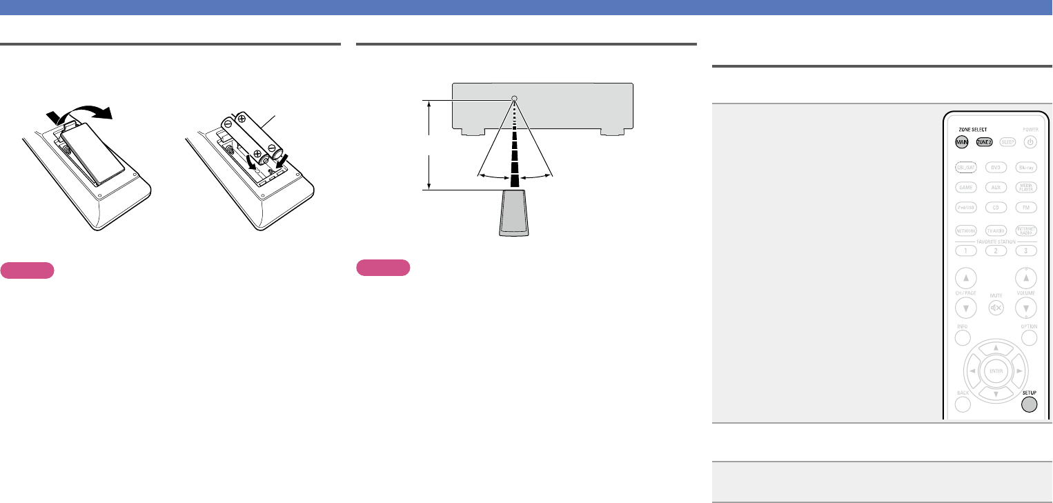
3
Set up the remote control unit
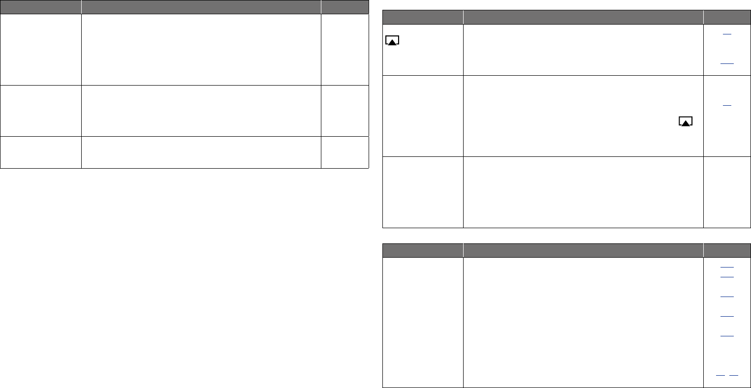
nSet up the zone mode
Press MAIN to switch the zone mode to the MAIN
ZONE.
MAIN lights.
Press MAIN
1
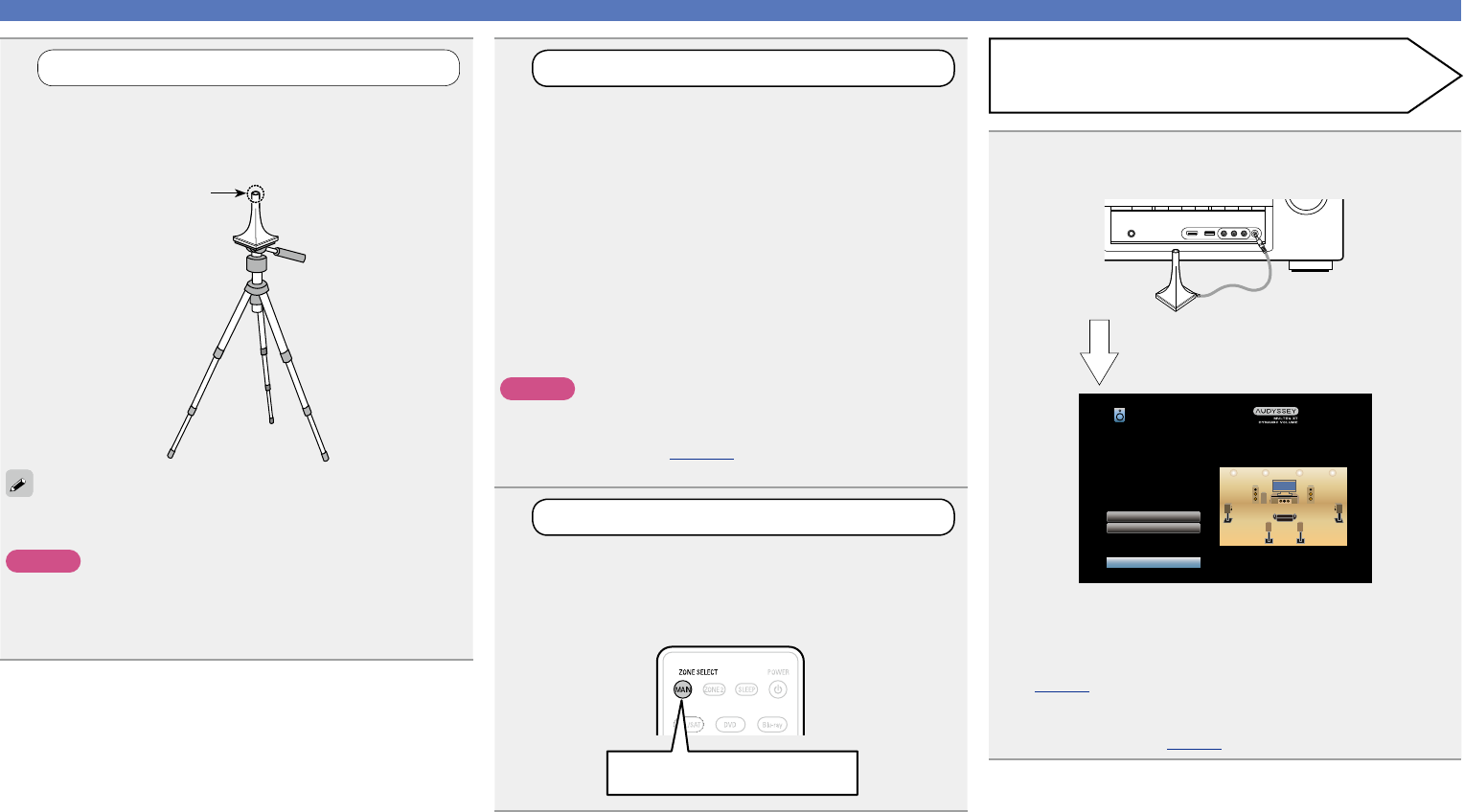
Prepare the included setup microphone
Mount the setup microphone on a tripod or stand
and place it in the main listening position.
When placing the setup microphone, adjust the height of the
sound receptor to the level of the listener’s ear.
Sound receptor
Setup
microphone
If you do not have a tripod or stand, set up the microphone on, for
example, a seat without a back.
NOTE
•Do not hold the setup microphone in your hand during
measurements.
•Avoid placing the setup microphone close to a seat back or wall as
sound reflections may give inaccurate results.
Set up speakers (Audyssey
®
Setup)
4
Connect the setup microphone to the SETUP MIC
jack of this unit.
Audyssey Setup
Amp Assign
Channel Select
Start
Your AV receiver can automatically measure the acoustics of
your room then optimize your speakers using the included
microphone.
Set the following items
if necessary.
When the setup microphone is
connected, the following screen is
displayed.
•Here, we explain setup using the example of 7.1-channel speaker
playback using surround back speakers.
For setup of surround back speaker systems other than
7.1-channels, follows steps 3 to 6 in “Set up “Amp Assign””
(vpage89).
If unused channels are set with “Channel Select”, measuring time
can be shortened. For setting, perform steps 7 to 12 of “Set up
“Channel Select”” (vpage90).
Preparation
Basic version
Advanced version
Informations
Basic version
v See overleaf
DVD
28
Preparation (Continued)
Detection & Measurement (Main)
Set up speakers (Audyssey
®
Setup)
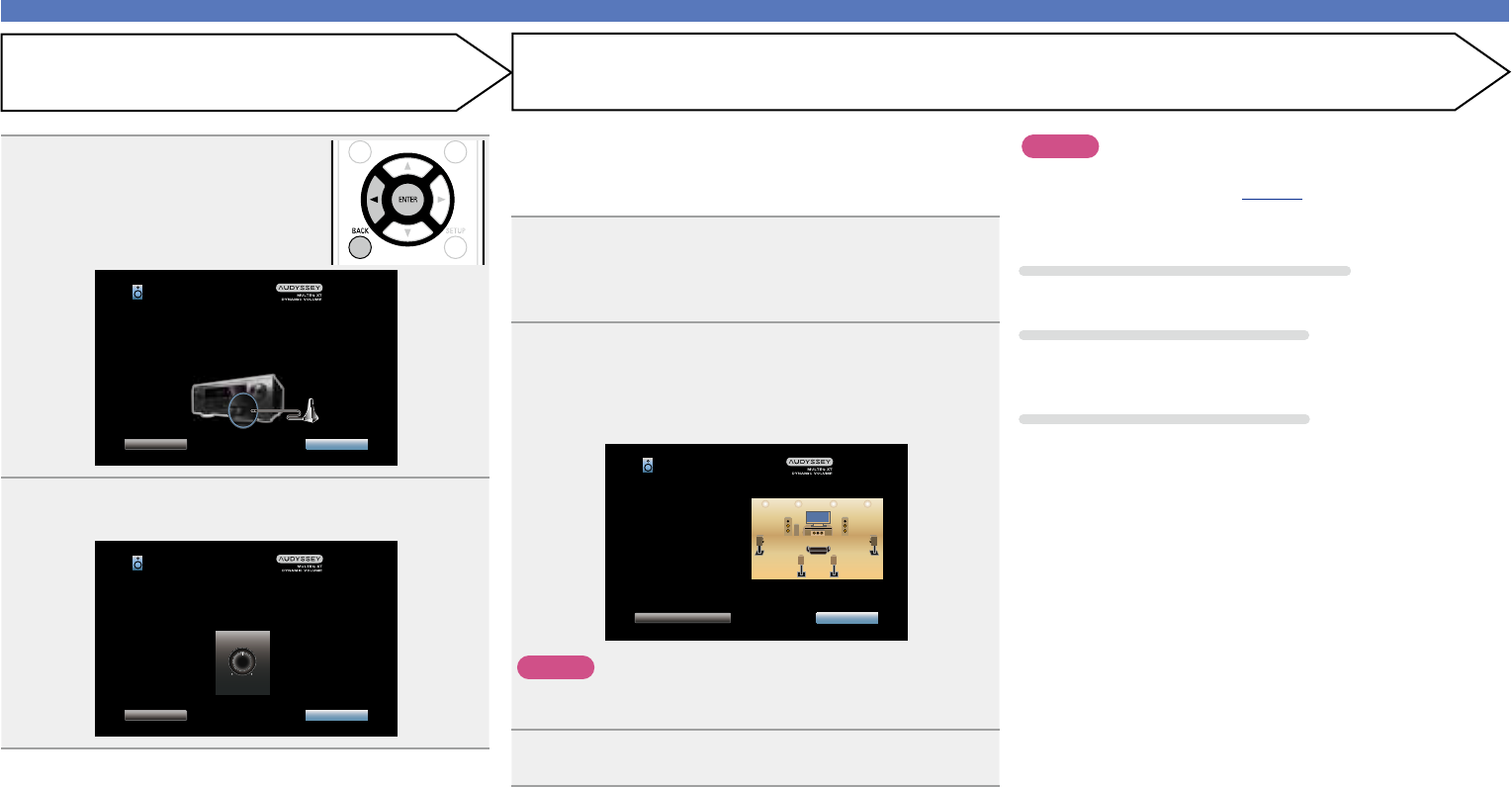
5
Select “Start” and then press
ENTER.
Audyssey Setup
BackNext
Connect the calibration microphone to the SETUP MIC input
on the front the AV receiver.
6
Select “Next” and then press ENTER.
The subwoofer volume setting screen is displayed.
Audyssey Setup
BackNext
VOLUME
MIN
MAX
If your subwoofer has a volume control on it, please set it
at 50%...
NOTE
If “Caution!” is displayed on TV screen:
Go to “Error messages” (vpage31). Check any related items,
and perform the necessary procedures.
If the problem is resolved, return and restart “Audyssey
®
Setup”.
Going back to the previous screen
Select “Back” and then press ENTER.
When measuring has stopped
qSelect “Back” and then press ENTER.
w Press o to select “Yes”, and then press ENTER.
Setting up the speakers again
Repeat the operation from step 4.
•This step automatically checks the speaker configuration and speaker
size, and calculates the channel level, distance, and crossover
frequency.
It also corrects distortion in the listening area.
7
Select “Begin Test” and then press ENTER.
When measuring begins, a test tone is output from each
speaker.
•Measurement requires several minutes.
8
The detected speakers are displayed.
•The illustration below shows an example of when the front
speakers, center speaker, subwoofer and surround speakers have
been detected.
Speaker Detection
Front
Center
Subwoofer
Surround
Surround Back
:Yes
:Yes
:Yes
:Yes
:2spkrs
Audyssey Setup
Repeat Last TestNext
NOTE
If a connected speaker is not displayed, the speaker may not be
connected correctly. Check the speaker connection.
9
Select “Next” and then press ENTER.
Basic version
Advanced version
Informations
Basic version
v See overleaf
DVD
29
Calculation
Set up speakers (Audyssey
®
Setup)
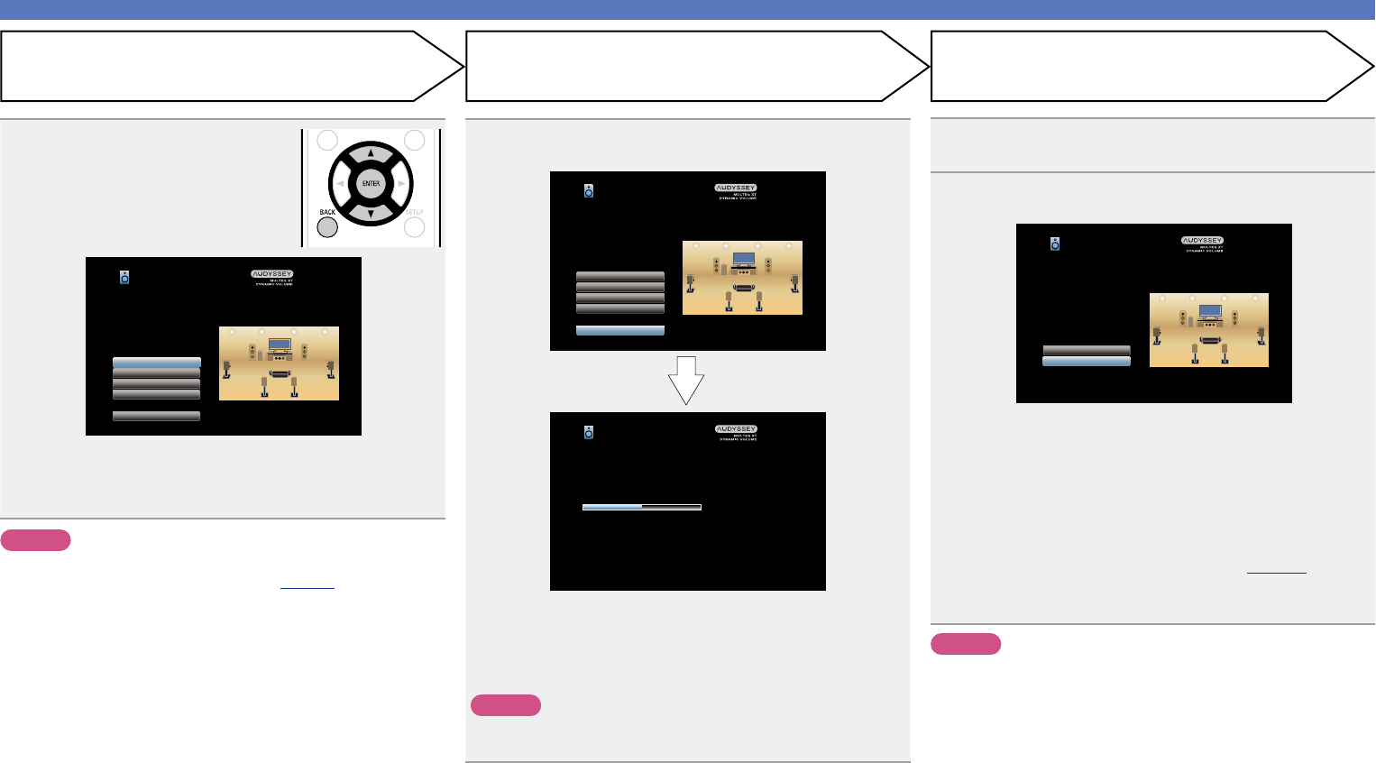
11
Repeat step 10, measuring positions 3 to 8.
When measurement of position 8 is completed, a
“Measurements finished.” message is displayed.
Repeat Last Test
Audyssey Setup
Calculation
Measurements finished.
12
Select “Calculation” and then press ENTER.
Measuring results are analyzed, and the frequency response of
each speaker in the listening room is determined.
Audyssey Setup
Calibration completed! Now calculating...Please wait.
50%
•Analysis takes several minutes to complete. The more speakers
and measurement positions that there are, the more time it takes
to perform the analysis.
Measurement (2nd – 8th)
•In this step, you will perform measurements at multiple positions
(two to eight positions) other than the main listening position.
•Just one position can be measured but measuring multiple positions
increases the accuracy of the correction of acoustic distortion within
the listening area.
10
Move the setup microphone to position 2, select
“Continue”, and then press ENTER.
The measurement of the second position starts. Measurements
can be made in up to eight positions.
Audyssey Setup
Calculation
Repeat Last Test
Continue
Place the microphone at ear level at the 3rd listening position,
then select "Continue"...
Audyssey Setup
Calculation
Continue
Place the microphone at ear level at the 2nd listening position,
then select "Continue"...
•To skip measuring the third and subsequent listening position, use
ui to select “Calculation” and press ENTER to proceed to step
13.
•To measure the second position again, use ui to select “Repeat
Last Test” and press ENTER.
Basic version
Advanced version
Informations
Basic version
v See overleaf
DVD
30
Set up speakers (Audyssey
®
Setup)
14
Select “Store” and then press ENTER.
Save the measurement results.
Audyssey Setup
Now storing...Please wait.
50%
Audyssey Setup
Distances
Speaker Config.
Levels
Crossovers
Store
Check processing results. To proceed, press “Store”.
•Saving the results requires about 10 seconds.
•During saving of measurements results, “Now storing...Please
wait.” is displayed. When saving is completed, “Storing complete.
Audyssey
®
Setup is now finished. Please unplug microphone.” is
displayed.
NOTE
During saving of measurement results, be sure not to turn off the
power.
15
Unplug the setup microphone from the unit’s SETUP
MIC jack.
16
Set Audyssey Dynamic Volume
®
.
Audyssey Setup
Yes
No
You can set Dynamic Volume function, which automatically
adjusts volume level for all content.
Do you want to enable?
•This feature adjusts the output volume to the optimal level while
constantly monitoring the level of the audio input to the unit.
Optimal volume control is performed automatically without any
loss in the dynamism and clarity of the sound when, for example,
the volume suddenly increases for commercials shown during
television programs.
nWhen turning Dynamic Volume on
•Press u to select “Yes”, and then press ENTER.
The unit automatically enters “Medium” (vpage109) mode.
nWhen turning Dynamic Volume off
•Press i to select “No”, and then press ENTER.
NOTE
After performing Audyssey
®
Setup, do not change the speaker
connections or subwoofer volume. In event of a change, perform
Audyssey
®
Setup again.
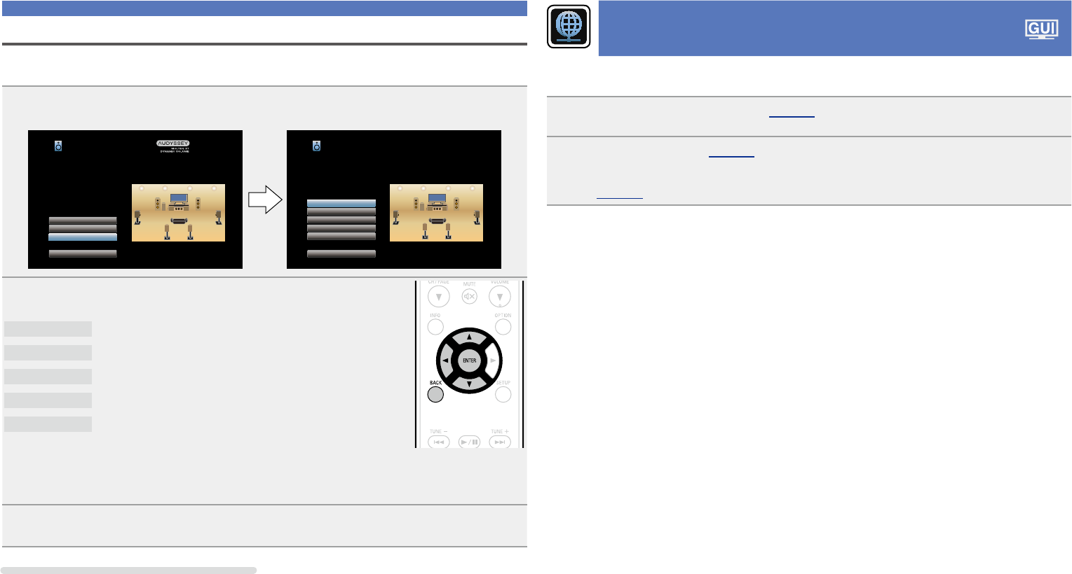
StoreFinishCheck
13
Use ui to select the item you
want to check, and then press
ENTER.
Audyssey Setup
Distances
Speaker Config.
Levels
Crossovers
Store
Check processing results. To proceed, press “Store”.
•Subwoofers may measure a greater reported distance than
the actual distance due to added electrical delay common in
subwoofers.
•If you want to check another item, press BACK.
NOTE
•If the result differs from the actual connection status, or if “Caution!”
is displayed, see “Error messages” (vpage31). Then carry out
Audyssey
®
Setup again.
• If you change speaker positions or orientation, perform Audyssey
®
Setup again to find the optimal equalizer settings.
Basic version
Advanced version
Informations
Basic version
DVD
31
Error messages
NOTE
•An error message is displayed if Audyssey
®
Setup could not be completed due to speaker placement, the measurement environment, etc. If an error message is displayed, check the relevant items and perform the
necessary measures. Then perform Audyssey
®
Setup again.
•If the result still differs from the actual connection status after remeasurement or the error message still appears, it is possible that the speakers are not connected properly. Turn this unit off, check the speaker
connections and repeat the measurement process from the beginning.
•Be sure to turn off the power before checking speaker connections.
ExamplesError detailsMeasures
Audyssey Setup
Retry
Caution! : Please check the cable connection and retry.
Microphone or Speaker is none
•The connected setup microphone is broken, or a device other than the
supplied setup microphone is connected.
•Not all speakers could be detected.
•Connect the included setup microphone to the SETUP MIC jack of this unit.
•Check the speaker connections.
Audyssey Setup
Retry
Caution!
Ambient noise is too high or level is too low
•There is too much noise in the room for accurate measurements to be
made.
•Speaker or subwoofer sound is too low for accurate measurements to be
made.
•Either turn off any device generating noise or move it away.
•Perform again when the surroundings are quieter.
•Check the speaker installation and the direction in which the speakers are
facing.
•Adjust the subwoofer’s volume.
Audyssey Setup
Retry
Caution! : Please check the cable connection and retry.
Front R:None
•The displayed speaker could not be detected.
(The screen on the left indicates that the front right speaker cannot be
detected.)
•Check the connections of the displayed speaker.
Skip Error
Audyssey Setup
RetryPhase Info.
Caution! : Please check the cable connection and retry.
Front R:Phase
•The displayed speaker is connected with the polarity reversed.
(The screen on the left indicates that the polarity phases of the front right
speakers are reversed.)
•Check the polarity of the displayed speaker.
•For some speakers, this error message may be
displayed even if the speaker is properly connected.
If you are sure the connection is correct, use op
to select “Skip Error”, then press ENTER.
Set up speakers (Audyssey
®
Setup)
Basic version
Advanced version
Informations
Basic version
DVD
32
Parameter Check
This function enables you to check the measurement results and equalizer characteristics after Audyssey
®
Setup.
1
Use ui to select “Parameter Check” and then press ENTER.
Audyssey Setup
Amp Assign
Channel Select
Parameter Check
Start
Your AV receiver can automatically measure the acoustics of
your room then optimize your speakers using the included
microphone.
Set the following items
if necessary.
Audyssey Setup/Parameter Check
Distances
Levels
Crossovers
Speaker Config.
Equalizers
Restore...
Check Audyssey Setup Measurement results.
2
Use ui to select the item you want to check, then press ENTER.
Measurement results for each speaker are displayed.
Speaker Config.
Check the speaker configuration.
Distances
Check the speaker distance.
Levels
Check the speaker channel level.
Crossovers
Check the speaker crossover frequency.
Equalizers
Check the equalizer.
•If “Equalizers” is selected, press
ui to select equalizing curve (“Audyssey” or “Audyssey Flat”) to
be checked.
Use ui to switch the display between the different speakers.
3
Press o or BACK.
The confirmation screen reappears. Repeat step 2.
Retrieving Audyssey
®
Setup settings
If you set “Restore...” to “Yes”, you can return to Audyssey
®
Setup measurement result (value calculated
at the start by MultEQ
®
XT) even when you have changed each setting manually.
Set up speakers (Audyssey
®
Setup)
Making the network settings
(Network)
This unit can be connected to a home network (LAN) to listen to Internet radio or play back music files and
still image (JPEG) files stored on a computer.
1
Connect the Ethernet cable (vpage 24 “Connecting to a home network (LAN)”).
2
Turn on this unit (vpage 33).
This unit performs automatic network setup due to the DHCP function.
When connecting to a network that has no DHCP function, perform the setting in “Settings”
(vpage128).
Basic version
Advanced version
Informations
Basic version
DVD
33
Playback (Basic operation)
Setup (vpage26)
nTurning the power on (vpage33)
nSelecting the input source (vpage33)
nAdjusting the master volume (vpage34)
nTurning off the sound temporarily (vpage34)
nPlaying a Blu-ray Disc player/DVD player
(vpage34)
nPlaying Super Audio CD (vpage34)
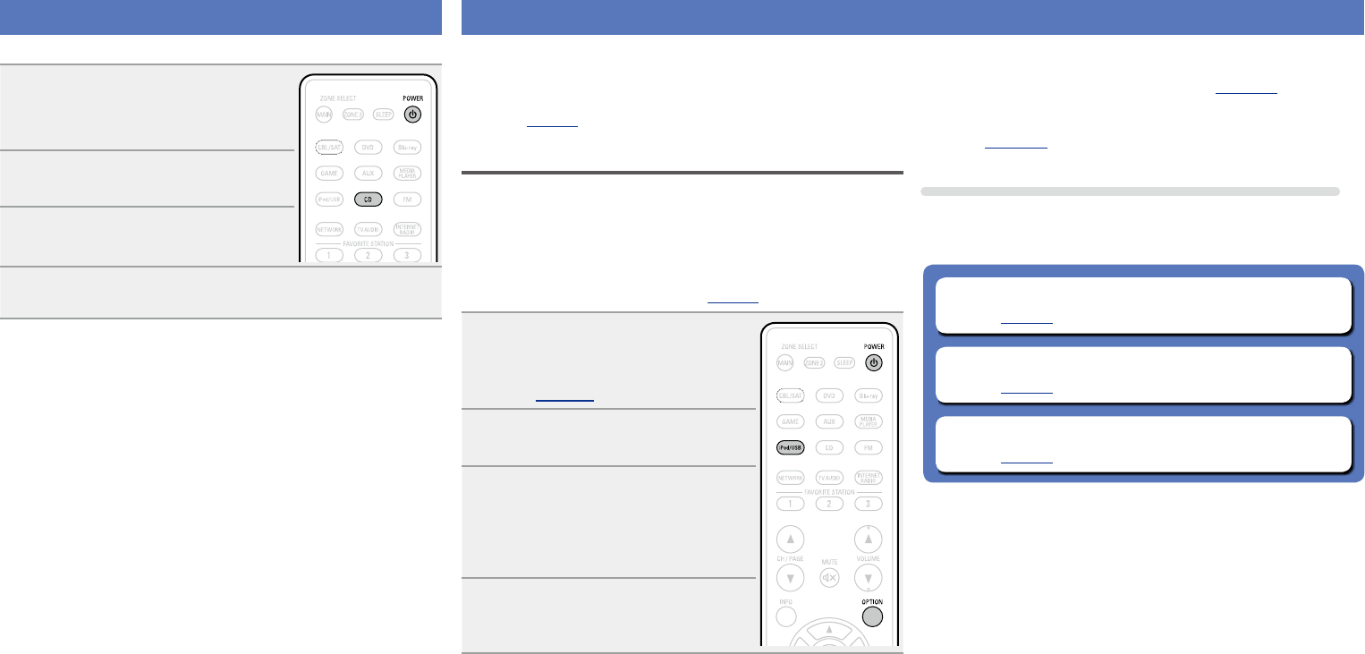
nPlaying a CD player (vpage35)
nPlaying an iPod (vpage35)
nPlaying a USB memory device (vpage38)
nListening to FM broadcasts (vpage41)
nListening to internet radio (vpage52)
nPlaying back files stored on a PC and NAS
(vpage55)
nUsing online services (vpage59)
nConvenient functions (vpage65)
nAirPlay function (vpage69)
Selecting a listening mode (Sound Mode)
(vpage71)
Playback (Advanced operation) (vpage91)
Important information
Before starting playback, make the connections between the different
devices and the settings on the unit.
NOTE
Also refer to the operating instructions of the connected devices
when playing them.
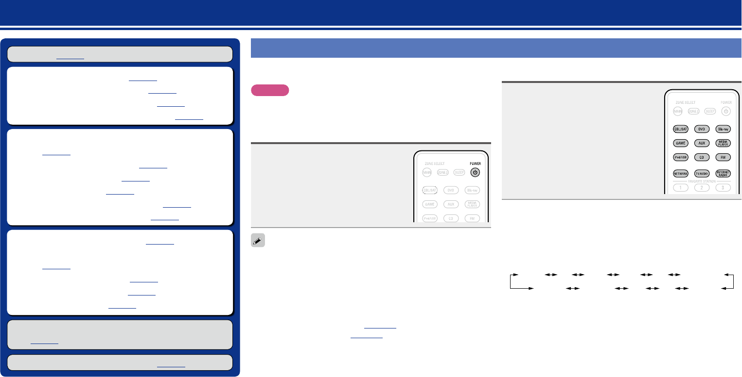
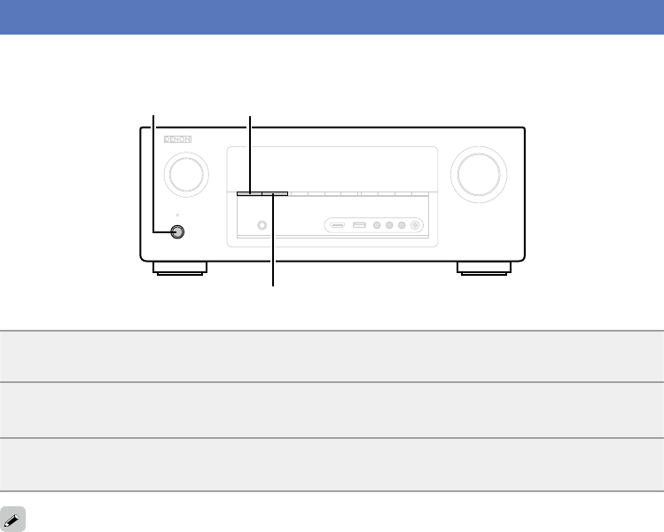
Turning the power on
Press POWER X to turn on power to
the unit.
The power indicator flashes green and the
power turns on.
You can also switch the power to standby by pressing X on the main
unit.
nWhen power is switched to standby
Press POWER X.
GPower indicator status in standby modeH
•Normal standby : Off
•When “HDMI Control” (vpage113) is set to “On” : Red
•When “IP Control” (vpage127) is set to “Always On” : Red
Selecting the input source
Press the input source select button
(CBL/SAT, DVD, Blu-ray, GAME,
AUX, MEDIA PLAYER, iPod/USB,
CD, FM, NETWORK, TV AUDIO or
INTERNET RADIO) to be played back.
The desired input source can be selected
directly.
You can also use the following operation to select an input
source.
nSelect the input source using the main unit
Turn SOURCE SELECT.
•Turning SOURCE SELECT switches the input source, as shown
below.
GAMEAUXMEDIA PLAYER
iPod/USBFMNETWORKCDTV AUDIO
Blu-rayDVDCBL/SAT
Basic version
Advanced version
Informations
Basic version
DVD
34
Adjusting the master volume
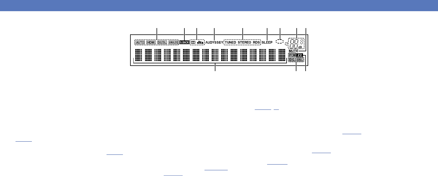
Use VOLUME df to adjust the
volume.
•The volume display method varies
depending on the “Scale” setting
(vpage108).
nWhen the “Scale” setting
(vpage108) is “0 – 98”
GAdjustable rangeH
0.0
0.5 – 98.0
nWhen the “Scale” setting (vpage108) is “–79.5dB –
18.0dB”
GAdjustable rangeH
– – –.–
–79.5dB – 18.0dB
•The variable range differs according to the input signal and channel
level setting.
You can also adjust the master volume by turning MASTER VOLUME
on the main unit.
Turning off the sound temporarily
Press MUTE :.
•“MUTE” indicator on the display flashes.
•: appears on a TV screen.
•The sound is reduced to the level set at “Mute Level” (vpage108).
•To cancel, press MUTE : again. Muting can also be canceled by
adjusting the master volume.
Important information
Playing a Blu-ray Disc player/DVD
player
The following describes the procedure for playing Blu-ray Disc player/
DVD player.
1
Prepare for playback.
q Turn on the power of the TV,
subwoofer and player.
w Change the TV input to the input of
this unit.
e Load the disc in the player.
2
Press POWER X to turn on power
to the unit.
3
Press Blu-ray or DVD to switch an input source for a
player used for playback.
4
Play the Blu-ray Disc player or DVD player.
•Make the necessary settings on the player (language setting,
subtitles setting, etc.) beforehand.
Playing Super Audio CD
The following describes the procedure for playing Super Audio CD.
1
Prepare for playback.
q Turn on the power of the subwoofer
and player.
w Load the disc in the player.
2
Press POWER X to turn on power
to the unit.
3
Perform the settings of the “Input Assign” menu
(vpage 117).
Assign HDMI connectors for the input source(example: DVD).
4
Press the input source select button (example: DVD)
to switch an input source assigned in step 3.
5
Set the audio input mode to “Auto” using the “Input
Mode” menu (vpage 119).
•The default setting of “Input Mode” is “Auto”.
6
Play the component connected to this unit.
When playing back Super Audio CD, DSD signals are converted into
PCM signals which are then converted into analog signals.
Basic version
Advanced version
Informations
Basic version
DVD
35
Playing a CD player
The following describes the procedure for playing CD player.
1
Prepare for playback.
q Turn on the power of the subwoofer
and player.
w Load the disc in the player.
2
Press POWER X to turn on power
to the unit.
3
Press CD to switch the input
source to “CD”.
4
Play the CD player.
Playing an iPod
You can use the USB cable provided with the iPod to connect the iPod
with the unit’s iPod/USB port and enjoy music stored on the iPod.
For information on the iPod models that can be played back with this
unit, see “Connecting an iPod or USB memory device to the iPod/USB
port” (vpage19).
Listening to music on an iPod
The iPod display modes include “Remote Mode” and “Browse
Mode”.
By default, “Remote Mode”, where you directly operate iPod itself
while seeing the iPod screen, is set.
To change to “Browse Mode”, where you perform operations while
having the iPod information displayed on the TV screen, see “Setting
Browse mode (Operation Mode)” (vpage36).
1
Using the USB cable provided
with the iPod, connect the
iPod to the iPod/USB port
(vpage 19).
2
Press POWER X to turn on
power to the unit.
3
Press iPod/USB to switch the
input source to “iPod/USB”.
“Remote iPod” is displayed on the
display of this unit.
•Nothing is displayed on the TV screen.
4
Operate iPod itself directly while
seeing the iPod screen to play
back music.
nStreaming music stored in iPhone, iPod touch,
or iPad directly to the unit (vpage69)
nPlaying iTunes music with this unit
(vpage69)
Operations available through the OPTION button
Press the OPTION button to display a menu of functions that can be
used on the TV screen. Select the function you want to use from this
menu. You can easily find and use the desired function.
nSetting Browse mode (Operation Mode)
(vpage36)
nPerforming repeat playback (Repeat)
(vpage37)
nPerforming random playback (Random)
(vpage37)
Basic version
Advanced version
Informations
Basic version
DVD
36
Playing an iPod
nSetting Browse mode (Operation Mode)
In this mode, various lists and screens during playback on iPod are
displayed on the TV screen.
This section describes the steps up to playing back tracks on iPod
in “Browse Mode”.
1
Press iPod/USB to switch the input source to “iPod/
USB”.
2
Press OPTION.
The option menu screen is displayed.
3
Select “Operation Mode”, then press ENTER.
The “Operation Mode” screen is displayed.
Operation Mode
Option
4
Use op to select “Browse
Mode”, then press ENTER.
The iPod screen is displayed.
Operation Mode
Browse Mode
•English letters, numbers and certain symbols are displayed.
Incompatible characters are displayed as “.” (period).
•Operations available for “Browse Mode” and “Remote Mode” are
listed below.
Display mode
Remote ModeBrowse Mode
Playable
files
Music file
PP
Video file
z
Active
buttons
Remote
control unit
(This unit)
PP
iPod
P
zOnly the sound is played.
5
Use ui to select the item, then press ENTER or p to
select the le to be played.
6
Press ENTER, p or 1/3.
Playback starts.
nAdjusting the sound quality (Restorer)
Make this setting at “Restorer” (vpage107) in the menu.
You can use the “Restorer” function to restore to a state close
to the audio before compression while correcting the bass feel to
enjoy a richer playback experience. The default setting is “Mode
3 (Low)”.
nChanging the screen display duration
Make this setting at “Audio Display” (vpage115) in the menu.
The default setting is “30s”.
Press uiop while the display is off to return to the original
screen.
nSwitching the screen display
In Browse mode, press STATUS on the main unit during playback.
The display switches between track title, artist name, and album
title etc. each time the button is pressed.
NOTE
•Depending on the type of iPod and the software version, some
functions may not operate.
•Note that DENON will accept no responsibility whatsoever for any
problems arising with the data on an iPod when using this unit in
conjunction with the iPod.
Basic version
Advanced version
Informations
Basic version
DVD
37
Playing an iPod
nPerforming repeat playback (Repeat)
1
Press OPTION while in Browse mode.
The option menu screen is displayed.
2
Use ui to select “Repeat”, then press ENTER.
OPTION
iPod
Title
Now Playing
Artist
Album
00:06100%
PreviousOptionPause
NextBack
Repeat
Option
Random
Operation Mode
3
Use op to select repeat playback mode.
OPTION
iPod
Title
Now Playing
Artist
Album
00:06100%
PreviousOptionPause
NextBack
Repeat
All
•Each time op is pressed, the setting is changed as shown below.
OffOne
All
Off
Repeat playback mode is canceled.
One
A file being played is played repeatedly.
All
All files in the folder currently being played are played
repeatedly.
4
Press ENTER.
The display returns to the playback screen.
nPerforming random playback (Random)
1
Press OPTION while in Browse mode.
The option menu screen is displayed.
2
Use ui to select “Random”, then press ENTER.
OPTION
iPod
Title
Now Playing
Artist
Album
00:06100%
PreviousOptionPause
NextBack
Repeat
Option
Random
Operation Mode
3
Use op to select random playback mode.
OPTION
iPod
Title
Now Playing
Artist
Album
00:06100%
PreviousOptionPause
NextBack
Random
Off
•Each time op is pressed, the setting is changed as shown below.
OffOn
Off
Disable random playback.
On
Enable random playback.
4
Press ENTER.
The display returns to the playback screen.
The random playback randomly selects a track to play back from all
tracks every time a track ends. Therefore, the same track may be
played back consecutively.
niPod operation buttons
Operation buttonsFunction
CH/PAGE df
Page search
INFO
Display of information such as the
source name, volume, and sound mode
name
OPTION
Browse / Remote mode switching /
Repeat playback /
Random playback
uiop
Cursor operation /
Auto search (cue, ui) /
Manual search (Press and hold, ui)
ENTER
(Press and release)
Enter
ENTER
(Press and hold)
Stop
BACKReturn
SETUPSetup menu
8 9
Auto search (cue)
1/3
Playback / Pause
Basic version
Advanced version
Informations
Basic version
DVD
38
Playing a USB memory device
Playing back music or still picture (JPEG) files recorded on a USB memory device.
Important information
•Only USB memory devices conforming to mass storage class and MTP (Media Transfer Protocol)
standards can be played on this unit.
•This unit is compatible with USB memory devices in “FAT16” or “FAT32” format.
•This unit is compatible with MP3 files conforming to “MPEG-1 Audio Layer-3” standards.
•File types that this unit can play back and specifications are shown below.
GSupported file typesH
Supported file typesUSB memory devices
z1
WMA (Windows Media Audio)
P
z2
MP3 (MPEG-1 Audio Layer-3)
P
WAV
P
MPEG-4 AAC
P
z3
FLAC (Free Lossless Audio Codec)
P
JPEG
P
z1 USB memory device
•This unit is compatible with MP3 ID3-Tag (Ver. 2) standard.
•This unit can show the artwork that was embedded by using MP3 ID3-Tag Ver. 2.3 or 2.4.
•This unit is compatible with WMA META tags.
•If the image size (pixels) of an album artwork exceeds 500 × 500 (WMA/MP3/WAV/FLAC) or 349 ×
349 (MPEG-4 AAC), then music may not be played back properly.
•WAV format Quantization bit length: 16 bits.
•FLAC format Quantization bit length: 16 or 24 bits.
z2 Copyright-protected files can be played on certain portable players compatible with MTP.
z3 Only files that are not protected by copyright can be played on this unit.
Content downloaded from pay sites on the Internet are copyright protected. Also, files encoded in
WMA format when ripped from a CD, etc. on a computer may be copyright protected, depending on
the computer’s settings.
NOTE
File types that this unit does not support are not displayed.
GCompatible formatsH
Sampling frequencyBit rateExtension
WMA (Windows Media Audio)32/44.1/48 kHz48 – 192 kbps.wma
•Video signals are only output when HDMI signals are played in the
PURE DIRECT mode.
•When in the PURE DIRECT mode, the menu screen is not displayed.
•When in the PURE DIRECT mode, the display turns off and appears
as if there is no electricity.
Basic version
Advanced version
Informations
Basic version
DVD
72
Selecting a listening mode
nListening mode
•The following listening modes can be selected using the MOVIE, MUSIC, GAME, and PURE buttons.
•Adjust the sound field effect with the menu “Surround Parameter” (vpage105) to enjoy your favorite sound mode.
Operation
button
Input signalListening mode
2-channel
z1
STEREO
DOLBY PLgx Cinema
z2
DOLBY PLg Cinema
z2
/
DOLBY PLg Cinema A-DSX
z4
DOLBY Pro Logic
z2
/
DOLBY Pro Logic A-DSX
z4
DTS NEO:6 Cinema
z2
/
DTS NEO:6 Cinema A-DSX
z4
DOLBY PLgz Height
z2
MULTI CH STEREO
MONO MOVIE
VIRTUAL
Multi-channel
z3
STEREO
Dolby Digital
DOLBY DIGITAL /
DOLBY DIGITAL A-DSX
z4
DOLBY DIGITAL EX
DOLBY DIGITAL + PLgx Cinema
DOLBY DIGITAL + PLgz
Dolby TrueHD
DOLBY TrueHD /
DOLBY TrueHD A-DSX
z4
DOLBY TrueHD + EX
DOLBY TrueHD + PLgx Cinema
DOLBY TrueHD + PLgz
Dolby Digital
Plus
DOLBY DIGITAL Plus /
DOLBY DIGITAL Plus A-DSX
z4
DOLBY DIGITAL Plus + EX
DOLBY DIGITAL Plus + PLgx Cinema
DOLBY DIGITAL Plus + PLgz
DTS
DTS SURROUND /
DTS SURROUND A-DSX
z4
DTS ES DSCRT 6.1
DTS ES MTRX 6.1
DTS 96/24
DTS + NEO:6
DTS + PLgx Cinema
DTS + PLgz
Operation
button
Input signalListening mode
DTS-HD /
DTS Express
DTS-HD HI RES /
DTS-HD HI RES A-DSX
z4
DTS-HD MSTR /
DTS-HD MSTR A-DSX
z4
DTS Express /
DTS Express A-DSX
z4
DTS-HD + NEO:6
DTS-HD + PLgx Cinema
DTS-HD + PLgz
PCM/DSD
multi-channel
MULTI CH IN /
MULTI CH IN A-DSX
z4
MULTI CH IN 7.1
MULTI IN + Dolby EX
MULTI IN + PLgx Cinema
MULTI IN + PLgz
Multi-channel
z3
MULTI CH STEREO
MONO MOVIE
VIRTUAL
z1 2-channel also includes analog input.
z2 This mode plays back 2-channel source in 5.1 or 7.1-channel
playback. It cannot be selected when headphones are used, or
when only front speakers are used.
z3 Some listening modes cannot be selected, depending on the
audio format or number of channels of the input signal. For
details, see “Types of input signals, and corresponding sound
modes” (vpage146).
z4 These modes add a front height or front wide channel to
the 5.1 channel surround using Audyssey DSX
®
processing
(vpage109).
Basic version
Advanced version
Informations
Basic version
v See overleaf
DVD
73
Selecting a listening mode
Operation
button
Input signalListening mode
DTS-HD /
DTS Express
DTS-HD HI RES /
DTS-HD HI RES A-DSX
z4
DTS-HD MSTR /
DTS-HD MSTR A-DSX
z4
DTS Express /
DTS Express A-DSX
z4
DTS-HD + NEO:6
DTS-HD + PLgx Music
DTS-HD + PLgz
PCM/DSD
multi-channel
MULTI CH IN /
MULTI CH IN A-DSX
z4
MULTI CH IN 7.1
MULTI IN + Dolby EX
MULTI IN + PLgx Music
MULTI IN + PLgz
Multi-channel
z3
MULTI CH STEREO
ROCK ARENA
JAZZ CLUB
MATRIX
VIRTUAL
Operation
button
Input signalListening mode
2-channel
z1
STEREO
DOLBY PLgx Music
z2
DOLBY PLg Music
z2
/
DOLBY PLg Music A-DSX
z4
DTS NEO:6 Music
z2
/
DTS NEO:6 Music A-DSX
z4
DOLBY PLgz Height
z2
MULTI CH STEREO
ROCK ARENA
JAZZ CLUB
MATRIX
VIRTUAL
Multi-channel
z3
STEREO
Dolby Digital
DOLBY DIGITAL /
DOLBY DIGITAL A-DSX
z4
DOLBY DIGITAL EX
DOLBY DIGITAL + PLgx Music
DOLBY DIGITAL + PLgz
Dolby TrueHD
DOLBY TrueHD /
DOLBY TrueHD A-DSX
z4
DOLBY TrueHD + EX
DOLBY TrueHD + PLgx Music
DOLBY TrueHD + PLgz
Dolby Digital
Plus
DOLBY DIGITAL Plus /
DOLBY DIGITAL Plus A-DSX
z4
DOLBY DIGITAL Plus + EX
DOLBY DIGITAL Plus + PLgx Music
DOLBY DIGITAL Plus + PLgz
DTS
DTS SURROUND /
DTS SURROUND A-DSX
z4
DTS ES DSCRT 6.1
DTS ES MTRX 6.1
DTS 96/24
DTS + NEO:6
DTS + PLgx Music
DTS + PLgz
z1 2-channel also includes analog input.
z2 This mode plays back 2-channel source in 5.1 or 7.1-channel
playback. It cannot be selected when headphones are used, or
when only front speakers are used.
z3 Some listening modes cannot be selected, depending on the
audio format or number of channels of the input signal. For
details, see “Types of input signals, and corresponding sound
modes” (vpage146).
z4 These modes add a front height or front wide channel to
the 5.1 channel surround using Audyssey DSX
®
processing
(vpage109).
Basic version
Advanced version
Informations
Basic version
v See overleaf
DVD
74
Selecting a listening mode
Operation
button
Input signalListening mode
All
DIRECT
PURE DIRECT
z1 2-channel also includes analog input.
z2 This mode plays back 2-channel source in 5.1 or 7.1-channel
playback. It cannot be selected when headphones are used, or
when only front speakers are used.
z3 Some listening modes cannot be selected, depending on the
audio format or number of channels of the input signal. For
details, see “Types of input signals, and corresponding sound
modes” (vpage146).
z4 These modes add a front height or front wide channel to
the 5.1 channel surround using Audyssey DSX
®
processing
(vpage109).
Operation
button
Input signalListening mode
2-channel
z1
STEREO
DOLBY PLgx Game
z2
DOLBY PLg Game
z2
/
DOLBY PLg Game A-DSX
z4
DOLBY PLgz Height
z2
MULTI CH STEREO
VIDEO GAME
VIRTUAL
Multi-channel
z3
STEREO
Dolby Digital
DOLBY DIGITAL /
DOLBY DIGITAL A-DSX
z4
DOLBY DIGITAL EX
DOLBY DIGITAL + PLgz
Dolby TrueHD
DOLBY TrueHD /
DOLBY TrueHD A-DSX
z4
DOLBY TrueHD + EX
DOLBY TrueHD + PLgz
Dolby Digital
Plus
DOLBY DIGITAL Plus /
DOLBY DIGITAL Plus A-DSX
z4
DOLBY DIGITAL Plus + EX
DOLBY DIGITAL Plus + PLgz
DTS
DTS SURROUND /
DTS SURROUND A-DSX
z4
DTS ES DSCRT 6.1
DTS ES MTRX 6.1
DTS 96/24
DTS + NEO:6
DTS + PLgz
DTS-HD /
DTS Express
DTS-HD HI RES /
DTS-HD HI RES A-DSX
z4
DTS-HD MSTR /
DTS-HD MSTR A-DSX
z4
DTS Express /
DTS Express A-DSX
z4
DTS-HD + NEO:6
DTS-HD + PLgz
PCM/DSD
multi-channel
MULTI CH IN /
MULTI CH IN A-DSX
z4
MULTI CH IN 7.1
MULTI IN + Dolby EX
MULTI IN + PLgz
Multi-channel
z3
MULTI CH STEREO
VIDEO GAME
VIRTUAL
Views on the TV screen or display
+ PL z DVD
qew
q Shows a decoder to be used.
•A DOLBY DIGITAL Plus decoder is displayed as “”.
w Shows a decoder that creates sound output from the surround
back speakers.
•“+ PLgz” indicates the front height sound from front height
speakers.
e Shows the name of the input source being played back.
Basic version
Advanced version
Informations
Basic version
v See overleaf
DVD
75
Selecting a listening mode
nDescription of listening mode types
Dolby listening mode
Listening mode typeDescription
DOLBY PLgx
z1
This mode can be selected when a Dolby Pro Logic gx decoder is used to
play back 2-channel source in 6.1/7.1-channel surround sound including the
surround back channel.
By adding the surround back channel, a stronger surround feeling is obtained
compared to Dolby Pro Logic g.
There are three playback modes: “Cinema” mode that is optimized for movie
playback, “Music” mode that is optimized for music playback, and “Game”
mode that is optimized for game play.
DOLBY PLgThis mode can be selected when a Dolby Pro Logic g decoder is used to play
back 2-channel source in 5.1-channel surround sound with a natural, realistic
feel.
DOLBY Pro LogicThis mode can be selected when a Dolby Pro Logic decoder is used to play
2-channel source in 4.1-channel surround sound (Left/Center/Right/Surround
Mono).
DOLBY PLgz
z2
This mode can be selected when a Dolby Pro Logic gz decoder is used to play
back 2-channel source in 7.1-channel surround sound with added front height
channel.
By adding a front height channel, the vertical expression is emphasized,
improving the three-dimensionality of the sound.
DOLBY DIGITALThis mode can be selected when playing sources recorded with Dolby Digital.
DOLBY DIGITAL EX
z1
Using a Dolby Digital EX decoder, this mode plays Dolby Digital source in
6.1/7.1 channel surround sound with added surround back channel.
By adding a surround back channel, spacial expressiveness and sound
localization are enhanced.
DOLBY TrueHDThis mode can be selected when playing sources recorded in Dolby TrueHD.
DOLBY DIGITAL PlusThis mode can be selected when playing sources recorded with Dolby Digital
Plus.
z1 This can be selected when “Speaker Config.” – “Surr. Back” is not set to “None”.
z2 This can be selected when “Speaker Config.” – “Front Height” is not set to “None”.
DTS listening mode
Listening mode typeDescription
DTS NEO:6This mode can be selected when a DTS NEO:6 decoder is used to play back
2-channel source in 6.1/7.1-channel surround sound including the surround
back channel.
There is a “Cinema” mode optimized for movie playback, and a “Music” mode
optimized for music playback.
DTS SURROUNDThis mode can be selected when playing sources recorded in DTS.
DTS ES DSCRT6.1
z
This mode is suitable for playing discs recorded in DTS-ES. The surround back
channel added using the discrete method is played as an independent channel.
Since all channels are independent, the 360-degree spacial expressiveness and
sound localization are enhanced.
DTS ES MTRX6.1
z
This mode is suitable for playing discs recorded in DTS-ES.
The surround back channel added to the surround-left and surround-right
channels by a matrix encoder at software recording time is decoded by this
unit’s matrix decoder and played from each channel (surround left, surround
right, surround back).
DTS 96/24This mode can be selected when playing sources recorded in DTS 96/24.
DTS-HDThis mode can be selected when playing sources recorded in DTS-HD.
DTS ExpressThis mode can be selected when playing sources recorded in DTS Express.
z This can be selected when “Speaker Config.” – “Surr. Back” is not set to “None”.
PCM multi-channel listening mode
Listening mode typeDescription
MULTI CH INThis mode can be selected when playing multi-channel PCM sources .
Basic version
Advanced version
Informations
Basic version
v See overleaf
DVD
76
Selecting a listening mode
Audyssey DSX listening mode
Listening mode typeDescription
Audyssey DSX
(A-DSX)
z
This mode creates playback for the new channels (front wide or front height) in
5.1-channel systems. By adding front wide or front high channels, the surround
sound effects sound more three dimensional and realistic.
z This can be selected when a setting other than “None” is selected for “Front Height” or “Front Wide”,
and a setting other than “None” is selected for “Center” in “Speaker Config.” (vpage122).
Original listening mode
Listening mode typeDescription
MULTI CH STEREOThis mode is for enjoying stereo sound from all speakers.
The same sound as that from the front speakers (L/R) is played back at the
same level from the surround speakers (L/R) and surround back speakers (L/R).
ROCK ARENAThis mode is for enjoying the atmosphere of a live concert in an arena.
JAZZ CLUBThis mode is for enjoying the atmosphere of a live concert in a jazz club.
MONO MOVIEThis mode is for playing monaural movie sources with surround sound.
When playing sources recorded in monaural in the “MONO MOVIE” mode,
the sound will be off balance with a single channel (left or right), so input to
both channels.
VIDEO GAMEThis mode is suited for achieving surround sound with video games.
MATRIXThis mode lets you add a spacious feel to stereo music sources.
VIRTUALThis mode is for enjoying surround effects using only the front speakers or
headphones.
STEREO listening mode
Listening mode typeDescription
STEREOThis is the mode for playing in stereo. The tone can be adjusted.
•Sound is output from the front left and right speakers and subwoofer.
•If multichannel signals are input, they are mixed down to 2-channel audio and
are played.
Direct listening mode
Listening mode typeDescription
DIRECTSound recorded in source is played as is.
PURE DIRECTThis mode is for playback in higher sound quality than in DIRECT mode.
Turn the display of the amplifier off to stop the analog video circuit. This
suppresses the source of noise that affects sound quality.
Basic version
Advanced version
Informations
Basic version
DVD
Advanced
version
77
F Installation/connection/setup of speakers (Advanced) vpage78
F Playback (Advanced operation) vpage91
F Playback in ZONE2 (Separate room) vpage97
F How to make detailed settings vpage99
Advanced version
Here, we explain functions and operations that let you make better use of this unit.
Basic version
Advanced version
Informations
Advanced version
DVD
78
Procedure for speaker settings
Speaker installation
Speaker connection (vpage80)
Set up speakers (vpage89)
Speaker installation
•Determine the speaker system depending on the number of speakers
you are using and install each speaker and subwoofer in the room.
Here, we explain how to install the speakers using a typical example.
•The speaker impedance should be from 6 to 16 Ω.
Use the illustration below as a guide for how high each speaker should
be installed. The height does not need to be exactly the same.
z1
z2
45˚
Surround
speaker
60 – 90 cm
GViewed from the sideH
Front height
speaker
•Point slightly
downwards
At least
1 m
Surround back
speaker
•Point slightly
downwards
Front
speaker
Front wide
speaker
z1 Recommended for Dolby Pro Logic gz
z2 Recommended for Audussey DSX
®
NOTE
You cannot have audio output from the surround back speakers, front
height speakers and front wide speakers simultaneously.
When 7.1ch speakers are installed using surround
back speakers
FLFR
C
SBLSBR
SL
SR
SW
z1
z2
z3
Listening
position
z1 22˚ – 30˚z2 90˚ – 110˚z3 135˚ – 150˚
GSpeaker abbreviationsH
FLFront speaker (L)SLSurround speaker (L)
FRFront speaker (R)SRSurround speaker (R)
CCenter speakerSBLSurround back speaker (L)
SWSubwooferSBRSurround back speaker (R)
Installation/connection/setup of speakers (Advanced)
Basic version
Advanced version
Informations
Advanced version
v See overleaf
DVD
79
Speaker installation
When 7.1ch speakers are installed using front
height speakers
When using Dolby Pro Logic gz or Audyssey DSX
®
, install front height
speakers.
FL
FR
FHRFHL
C
SL
SR
SW
z1
z2
z3
Listening
position
z1 22˚ – 30˚z2 22˚ – 45˚z3 90˚ – 110˚
GSpeaker abbreviationsH
FLFront speaker (L)SBSurround back speaker
FRFront speaker (R)FHLFront height speaker (L)
CCenter speakerFHRFront height speaker (R)
SWSubwooferFWLFront wide speaker (L)
SLSurround speaker (L)FWRFront wide speaker (R)
SRSurround speaker (R)
When 7.1ch speakers are installed using front wide
speakers
When using Audyssey DSX
®
, install front wide speakers.
FL
FR
SL
SR
FWL
FWR
SW
C
z1
z2
z3
Listening
position
z1 22˚ – 30˚z3 55˚ – 60˚ z3 90˚ – 110˚
When 6.1ch speakers are installed
FLFR
C
SB
SL
SR
SW
z1
z2
Listening position
z1 22˚ – 30˚z2 90˚ – 110˚
When 5.1ch speakers are installed
FLFR
SW
C
SL
SR
z1
z2
Listening position
z1 22˚ – 30˚z2 120˚
When Front A/B speakers are installed
FR(A)FR(B)
SW
FL(B)FL(A)
Listening position
Basic version
Advanced version
Informations
Advanced version
DVD
80
Speaker connection
Here, we connect the speakers in the room to this unit.
This section explains how to connect them using a typical example.
nConnecting 7.1-channel speakers using surround back speakers (vpage81)
nConnecting 7.1-channel speakers using front height speakers (vpage82)
nConnecting 7.1-channel speakers using front wide speakers (vpage83)
nConnecting 6.1-channel speakers using one surround back speaker (vpage84)
nConnecting 5.1-channel speakers (vpage85)
nConnecting front A/B speakers (vpage86)
nConnecting 2.1-channel speakers (vpage87)
nConnecting front speakers with a bi-amp connection (vpage88)
NOTE
•Disconnect this unit’s power plug from the power outlet before connecting the speakers. Also,
turn off the subwoofer.
•Connect so that the speaker cable core wires do not protrude from the speaker terminal. The
protection circuit may be activated if the core wires touch the rear panel or if the + and – sides
touch each other (vpage153 “Protection Circuit”).
•Never touch the speaker terminals while the power supply is connected. Doing so could result
in electric shock. When the “Setup Assistant” is running, follow the instructions in the “Setup
Assistant” screen for making connections. (Power is not supplied to the speaker terminals while
the “Setup Assistant” is running.)
•Use speakers with the speaker impedances shown below.
Speaker terminalsSpeaker impedance
FRONT
6 – 16 Ω
CENTER
SURROUND
SURROUND BACK
Connecting the speaker cables
Carefully check the left (L) and right (R) channels and + (red) and – (black) polarities on the speakers being
connected to this unit, and be sure to interconnect the channels and polarities correctly.
1
Peel off about 10 mm of sheathing from the tip of the speaker
cable, then either twist the core wire tightly or terminate it.
2
Turn the speaker terminal counterclockwise to loosen it.
3
Insert the speaker cable’s core wire to the hilt into the speaker
terminal.
4
Turn the speaker terminal clockwise to tighten it.
Connecting the subwoofer
Use a subwoofer cable to connect the subwoofer.
nFor connecting two subwoofers
Two subwoofers can be connected to this unit.
The same signal is output from each subwoofer
terminal.
Basic version
Advanced version
Informations
Advanced version
DVD
81
Speaker connection
Connecting 7.1-channel speakers using surround back speakers
The illustration on the right shows a connection example for performing 7.1-channel playback using the
surround back speakers.
To perform 7.1-channel playback using the surround back speakers, set “Assign Mode” to “Surround
Back” in steps 3 to 5 for “Set up “Amp Assign”” (vpage89).
Cables used for connections
Audio cable (sold separately)
Speaker
cable
Subwoofer
cable
NOTE
•For speaker cable connections, see page80.
•For speaker impedance , see page80.
FLFR
C
SL
SR
SW
SBLSBR
Basic version
Advanced version
Informations
Advanced version
DVD
82
FLFR
C
SL
SR
SW
FHRFHL
Connecting 7.1-channel speakers using front height speakers
The illustration on the right shows a connection example for performing 7.1-channel playback using the
front height speakers.
To perform 7.1-channel playback using the front height speaker, set “Assign Mode” to “Front Height” in
steps 3 to 5 for “Set up “Amp Assign”” (vpage89).
Cables used for connections
Audio cable (sold separately)
Speaker
cable
Subwoofer
cable
When using Dolby Pro Logic gz or Audyssey DSX
®
, install front height speakers.
NOTE
•For speaker cable connections, see page80.
•For speaker impedance , see page80.
Speaker connection
Basic version
Advanced version
Informations
Advanced version
DVD
83
FLFR
C
SL
SR
SW
FWR
FWL
Connecting 7.1-channel speakers using front wide speakers
The illustration on the right shows a connection example for performing 7.1-channel playback using the
front wide speakers.
To perform 7.1-channel playback using the front wide speaker, set “Assign Mode” to “Front Wide” in
steps 3 to 5 for “Set up “Amp Assign”” (vpage89).
Cables used for connections
Audio cable (sold separately)
Speaker
cable
Subwoofer
cable
When using Audyssey DSX
®
, install front wide speakers.
NOTE
•For speaker cable connections, see page80.
•For speaker impedance , see page80.
Speaker connection
Basic version
Advanced version
Informations
Advanced version
DVD
84
Speaker connection
Connecting 6.1-channel speakers using one surround back
speaker
If using only one surround back speaker, connect to the “L” side of the SURROUND BACK terminal.
For speaker settings in this case, see “When 6.1ch speakers are installed” (vpage79).
To perform 6.1-channel playback using the surround back speaker, set “Assign Mode” to “Surround Back”
in steps 3 to 5 for “Set up “Amp Assign”” (vpage89).
Also use the “Speaker Config.” setting (vpage123) to set “Surr. Back” to “1spkr”.
Cables used for connections
Audio cable (sold separately)
Speaker
cable
Subwoofer
cable
NOTE
•For speaker cable connections, see page80.
•For speaker impedance , see page80.
FLFR
C
SL
SR
SW
SB
Basic version
Advanced version
Informations
Advanced version
DVD
85
Speaker connection
SL
SR
FLFR
C
SW
Connecting 5.1-channel speakers
To perform 5.1-channel playback, set “Assign Mode” to “Surround Back” in steps 3 to 5 for “Set up “Amp
Assign”” (vpage89).
Cables used for connections
Audio cable (sold separately)
Speaker
cable
Subwoofer
cable
NOTE
•For speaker cable connections, see page80.
•For speaker impedance , see page80.
Basic version
Advanced version
Informations
Advanced version
DVD
86
Speaker connection
FL(A)FL(B)FR(B)FR(A)
SW
Connecting front A/B speakers
You can connect a second set of speakers to this unit and use them for playback.
In this case, set “Assign Mode” to “Front B” in steps 3 to 5 for “Set up “Amp Assign”” (vpage89).
Cables used for connections
Audio cable (sold separately)
Speaker
cable
Subwoofer
cable
For multichannel playback, connect center, surround, surround back, and front speakers and a subwoofer.
Front speakers can be used separately, depending on the speaker’s specifications or playback source such
as front speakers (A) for multichannel playback and front speakers (B) for 2-channel playback (vpage125
“Front Speaker Setup”).
NOTE
•For speaker cable connections, see page80.
•For speaker impedance , see page80.
Basic version
Advanced version
Informations
Advanced version
DVD
87
Speaker connection
FLFR
SW
Connecting 2.1-channel speakers
Cables used for connections
Audio cable (sold separately)
Speaker
cable
Subwoofer
cable
NOTE
•For speaker cable connections, see page80.
•For speaker impedance , see page80.
nFor connecting two subwoofers
Two subwoofers can be connected to this unit.
The same signal is output from each subwoofer terminal.
Basic version
Advanced version
Informations
Advanced version
DVD
88
Speaker connection
FLFR
SW
wqwq
(R) (L)
Connecting front speakers with a bi-amp connection
•You cannot use surround back speakers in a bi-amp connection. Use front speakers that support a bi-amp
connection and connect the speakers to the FRONT speaker terminals and the SURROUND BACK
speaker terminals.
In this case, set “Assign Mode” to “Bi-AMP” in steps 3 to 5 for “Set up “Amp Assign”” (vpage89).
•A bi-amp connection is to connect separate amplifiers to the tweeter terminals and woofer terminals of
speakers compatible with the bi-amp function. This prevents the back electromotive force (returned force
without output) of the woofer sent to the tweeter, which affects the sound quality of the tweeter, and
you can enjoy playback with higher-quality sound.
Cables used for connections
Audio cable (sold separately)
Speaker
cable
Subwoofer
cable
For multichannel playback, connect front, center, surround, and surround back speakers and a subwoofer.
NOTE
•For speaker cable connections, see page80.
•For speaker impedance , see page80.
•When making bi-amp connections, be sure to remove the short-circuiting plate or wire between the
speaker’s woofer and tweeter terminals.
Basic version
Advanced version
Informations
Advanced version
DVD
89
1
Set up the
remote control unit
nSet up the zone mode
Press MAIN to switch the zone mode to the MAIN
ZONE.
MAIN lights.
Press MAIN
2
Connect the setup microphone.
Audyssey Setup
Amp Assign
Channel Select
Start
Your AV receiver can automatically measure the acoustics of
your room then optimize your speakers using the included
microphone.
Set the following items
if necessary.
When the setup microphone is
connected, the following screen is
displayed.
Set up speakers
around items indicate the settings.
First install and connect the speakers to this unit.
Before Audyssey
®
Setup measurement, the settings shown below can be made.
•Changing the amplifier assignment (Amp Assign)
The signal output from the SURROUND BACK speaker terminal of this unit can be switched to match your speaker environment (vpage89 “Set up “Amp Assign””).
•Setting the channels to be used (Channel Select)
If channels that are not to be used are set in advance, measurement for the set channels is skipped, and measuring time can be reduced. You can also change the number of surround back speakers (vpage90
“Set up “Channel Select””).
3
Set up “Amp Assign”
Use ui to select “Amp Assign”, and then press
ENTER.
Amp Assign
Assign ModeSurround Back
ZONE2:
Selects how to use the internal amplifiers
Audyssey Setup
Amp Assign
Channel Select
Start
Your AV receiver can automatically measure the acoustics of
your room then optimize your speakers using the included
microphone.
Set the following items
if necessary.
4
Select “Assign Mode”, and then press ENTER.
Basic version
Advanced version
Informations
Advanced version
v See overleaf
DVD
90
Set up speakers
7
Set up “Channel Select”
Use ui to select “Channel Select”, and then press
ENTER.
Channel Select
SubwooferMeasure
Audyssey Setup
Amp Assign
Channel Select
Start
Your AV receiver can automatically measure the acoustics of
your room then optimize your speakers using the included
microphone.
Set the following items
if necessary.
8
Use ui to select a channel, and then press ENTER.
Front
Select for setting the front speakers to be used. In this
case, go to step 9.
•“Front” can be set when “Assign Mode” is set to
“Front B”.
Subwoofer
Select for no subwoofers to be used. In this case, go
to step 10.
Surround
Back
Select the number of surround back speakers to be
used. In this case, go to step 11.
•“Surround Back” can be set when “Assign Mode” is
set to “Surround Back”.
9
Use op to select a front speaker, and then press
ENTER.
ASelect this to use front speaker A.
B
Select this to use front speaker B.
A+B
Select this to use front speakers A and B simultaneously.
10
Use op to set whether or not a subwoofer channel is
measured, and then press ENTER.
MeasureSet for measuring a subwoofer.
Skip
Set for no measuring of a subwoofer.
11
Use op to set whether or not a surround back
channel is measured, and then press ENTER.
Measure
(2spkrs)
Set for measuring two surround back speakers.
Measure
(1spkr)
Set for measuring a surround back speaker.
Skip
Set for no measuring of a surround back speaker.
12
Press o or BACK.
Proceed to page28
Preparation
step 5.
NOTE
After performing Audyssey
®
Setup, do not change the speaker
connections or subwoofer volume. In event of a change, perform
Audyssey
®
Setup again.
5
Use op to select the
conguration of the connected
speakers, and then press
ENTER.
Surround Back
Setting for 7.1-channel playback using surround
back speakers.
ZONE2
Setting to assign the unit’s built-in power amplifier
for ZONE2 and output the audio in stereo.
Bi-AMP
Setting to use the front speakers via the bi-amp
connection.
Front B
Setting to use the second set of front speakers for
playback.
Front Height
Setting for 7.1-channel playback using front height
speakers.
Front Wide
Setting for 7.1-channel playback using front wide
speakers.
6
Press o or BACK to exit the “Amp Assign” setting.
Basic version
Advanced version
Informations
Advanced version
DVD
91
Setup (vpage26)
Playback (Basic operation) (vpage33)
Selecting a listening mode (Sound Mode)
(vpage71)
nHDMI control function (vpage91)
nSleep timer function (vpage92)
nQuick select function (vpage93)
nREC OUT mode (vpage94)
nWeb control function (vpage95)
nVarious memory functions (vpage96)
Playback (Advanced operation)
HDMI control function
If you connect the unit and an HDMI control function compatible TV or
player with an HDMI cable and then enable the HDMI control function
setting on each device, the devices will be able to control each other.
nOperations possible by HDMI control
•This unit power off can be linked to the TV power off step.
•You can switch audio output devices with a TV operation.
When you set “Output audio from amp” in the TV audio output
setup operation, you can switch the amp power on.
•You can adjust this unit volume in the TV volume adjustment
operation.
•You can switch this unit input sources through linkage to TV
input switching.
•When playing the player, this unit input source switches to the
source for that player.
•If you switch the input source of the unit to “TV AUDIO”, you
can play TV audio with this unit (vpage 8 “About ARC
(Audio Return Channel) function”).
•When “HDMI Control” (vpage113) in the menu is set to
“On”, signals input to the HDMI input connector are output to
the television or other device connected to the HDMI output
connector, even if the power of this unit is in standby (pass-
through function).
•To use this unit to play the audio of a TV that does not support
the ARC function, connect the TV with an optical-digital or analog
connection (vpage8).
•To use the pass-through function, connect an HDMI connection
device that is compatible with HDMI control.
nSetting procedure
1
Set the HDMI output connector corresponding with
the HDMI control function.
Set “HDMI Control” (vpage113) to “On”.
2
Turn the power on for all the devices connected by
HDMI cable.
3
Set the HDMI control function for all devices
connected by HDMI cable.
•Please consult the operating instructions for the connected devices
to check the settings.
•Carry out steps 2 and 3 should any of the devices be unplugged.
4
Switch the television input to the HDMI input
connected to this unit.
5
Switch this unit input to the HDMI input source and
check if the picture from the player is ok.
6
When you turn the TV’s power to standby, check
that the power of this unit also goes to standby.
Basic version
Advanced version
Informations
Advanced version
v See overleaf
DVD
92
HDMI control function
If the HDMI control function does not operate properly, check the
following points.
•Is the TV or player compatible with the HDMI control function?
•Is “HDMI Control” (vpage113) set to “On”?
•Is “Power Off Control” (vpage113) set to “All” or “Video”?
•Is “Control Monitor” (vpage113 set for the monitor output
connected to television?
•Is the “Control Monitor” setting (vpage113) of the menu set
to the TV that uses the HDMI control function when this unit is
connected to two TVs that support HDMI connectors?
•Are the HDMI control function settings of all devices correct?
NOTE
•When “HDMI Control” is set to “On”, it consumes more standby
power.
•The HDMI control function controls operations of a TV that is
compatible with the HDMI control function. Make sure that the TV
and HDMI are connected when you perform HDMI control.
•Some functions may not operate depending on the connected TV
or player. Check the owner’s manual of each device for details
beforehand.
•When “Power Off Control” on the menu is set to “Off”
(vpage113), this unit is not set to standby even if the connected
device is in the standby mode.
•When connection changes are implemented, such as adding
connections to HDMI devices, linked operations may be initialized.
In this case, you will need to reconfigure the settings.
•When “HDMI Control” is set to “On”, it is not possible to assign an
HDMI connector to “TV AUDIO” at “Input Assign” (vpage117).
•Should any of the operations below be performed, the interlocking
function may be reset, in which case, repeat steps 2 and 3.
•“Input Assign” – “HDMI” (vpage117) setting has changed.
•“Video Output” (vpage112) setting is changed.
•There is a change to the connection between the devices and the
HDMI, or an increase in devices.
Sleep timer function
•You can have the power automatically switched to standby once a
set time has elapsed. This is convenient for viewing and listening
while going to sleep.
•The sleep timer function can be set for each zone (vpage98
“Sleep timer function”). (The MAIN ZONE setting method is
explained here.)
1
Press MAIN to switch the zone mode to the MAIN
ZONE.
MAIN lights.
2
Press SLEEP and display the time
you want to set.
The indicator on the display
lights.
•The time switches as shown below
each time SLEEP is pressed.
Off10 min20304050
60807090100
110
120
To confirm the countdown time before putting the
unit to sleep
Press SLEEP.
“Sleep : zmin” appears on the display.
z Countdown time
To cancel the sleep timer
Press SLEEP to set “Off”.
The indicator on the display turns off.
•The sleep timer setting is canceled if this unit’s power is set to
standby.
•The sleep timer function can be set separately for the different zones
(vpage98 “Sleep timer function”).
NOTE
The sleep timer function cannot turn off the power of devices
connected to this unit. To turn off the power of those connected
devices, set up sleep timers on the connected devices themselves.
Basic version
Advanced version
Informations
Advanced version
DVD
93
Quick select function
You can save settings such as the input source selection, volume
level, and sound mode at the QUICK SELECT 1 – 4 buttons.
You can simply press one of the set QUICK SELECT buttons for
subsequent playback to switch to various saved settings all at once.
•By saving frequently used settings at the QUICK SELECT 1 – 4
buttons, you will always be able to easily call up the same playback
environment.
Press QUICK SELECT.
The Quick Select settings for the button you pressed are called up.
•The default settings of each QUICK SELECT are as shown below.
ButtonInput sourceVolume
Sound
Mode
QUICK SELECT 1CBL/SAT40STEREO
QUICK SELECT 2Blu-ray40STEREO
QUICK SELECT 3GAME40STEREO
QUICK SELECT 4NETWORK40STEREO
Changing the Quick Select Name
On this unit, you can change the Quick Select name displayed on the
menu to the name that you prefer.
For the name change method, see “Quick Select Names”
(vpage132).
nChanging the settings
1
Set the items below to the settings you want to save.
qInput source
z
(vpage33)
wVolume (vpage34)
eSound Mode (vpage71)
r Audyssey
(Audyssey MultEQ
®
XT, Audyssey Dynamic EQ
®
, Audyssey
Dynamic Volume
®
) (vpage108)
2
Press and hold the desired QUICK SELECT until
“Quickz Memory” appears on the display.
The current settings will be memorized.
z The number for the
QUICK SELECT button you pressed is
displayed.
Basic version
Advanced version
Informations
Advanced version
DVD
94
REC OUT mode
•When using the audio/video recording connectors (MEDIA PLAYER
outputs), you can record the audio or video from a different program
source while listening to the currently played track.
•For the connection method, see “Connecting a media player”
(vpage18).
1
Press ZONE2 / REC SOURCE until “RECOUT
SOURCE” is displayed.
2
Press ZONE2 / REC SOURCE to choose the input
source to be recorded.
ZONE2 SOURCEZONE2 CBL/SATZONE2 DVD
····
····
RECOUT DVDRECOUT CBL/SATRECOUT SOURCE
3
Start recording.
•For operating instructions, refer to the respective device’s
operating instructions.
•To cancel, press ZONE2 / REC SOURCE until “ZONE2 SOURCE” is
displayed.
•Make a test recording before starting the actual recording.
•The digital signal input into the HDMI, COAXIAL and OPTICAL
connectors is not output from the analog REC OUT connector.
•Sources selected with the REC OUT mode are output from ZONE2
as well.
•The operable buttons on the remote control unit in REC OUT mode
while it is in the operating mode for ZONE2 are as follows:
•ZONE SELECT buttons
•MUTE button (:)
•VOLUME button (df)
NOTE
•Recordings you make are for your personal enjoyment and should
not be used for other purposes without permission of the copyright
holder.
•Input sources for which “Hide” is selected at “Hide Sources”
(vpage119) cannot be selected.
•To record video signals through this unit, use the video cable for
connection between this unit and the player.
Basic version
Advanced version
Informations
Advanced version
DVD
95
Web control function
You can control this unit from a web control screen on a web browser.
•This unit and the PC need to be connected to the network properly
(vpage24 “Connecting to a home network (LAN)”) in order to
use the web control function.
•Depending on the settings of your security-related software, you
may not be able to access this unit from your PC. If this is the case,
then change the settings of the security-related software.
1
Switch the “IP Control” setting to “Always On”
(vpage 127).
2
Check the IP address of this unit with “Information”
(vpage 127).
Displays the current network settings of the AVR
Network/Information
Friendly name
DHCP
IP Address
MAC Address
DENON AVR-2313
On
192.168.100.19
0005cd000000
Checking the IP address.
3
Start up the web browser.
4
Enter the IP address of this unit in browser’s address
box.
For example, if the IP address of this unit is “192.168.100.19”,
enter “http://192.168.100.19/”.
http://192.168.100.19/index.asp
INDEX
File
EditViewToolsHelpFavorites
DENON AVR-2313
Web Controller
Web Controller Config.
MAIN ZONE
ZONE2
40.0
CBL/SAT
Blu-ray
Setup Menu
q
qEntering the IP address.
•By adding this unit’s IP address to the browser’s bookmark,
you can display the web control screen using the bookmark
function the next time you use the browser. If you are using a
DHCP server and “IP Control” (vpage127) is set to “Off In
Standby”, turning the power on/off changes the IP address.
5
When the top menu is displayed, click on the menu
item you want to operate.
http://192.168.100.19/index.asp
INDEX
File
EditViewToolsHelpFavorites
DENON AVR-2313
Web Controller
Web Controller Config.
MAIN ZONE
ZONE2
40.0
CBL/SAT
Blu-ray
Setup Menu
w
e
r
wClick when you select the zone to operate. (vGExample 1H)
eClick when you operate the setup menu.
rClick to change the Web control screen setting.
(vGExample 3H)
6
Operate.
GExample 1H MAIN ZONE control screen
ZONE CONTROL
NETWORK
iPod/USB
FM
QUICK SELECT
RELOAD
Add To Your Favorite
Top Menu
MAIN ZONE
SLEEP
40.0
DENON AVR-2313
CBL/SAT
FAVORITE STATION
STEREO
CBL/SAT
DVD
Blu-ray
GAME
AUXMEDIA PLAYER
iPod/USB
CD
FM
NETWORK
TV AUDIO
Internet Radio
123
MOVIE
DIRECTSTEREO
STANDARDSIMULATION
MUSICGAMEPURE
u
t
i
y
Q0
Q1
Q2
Q5
Q3
Q4
Q6
o
tClick the menu item from which you want to make settings.
The display on the right becomes the individual setting screens.
(vGExample 4H)
yClick when you perform a power operation of the unit.
uClick when you update to the latest information.
Normally, there is a change to the latest information each time
you operate. When operating from the main unit, click this or else
the screen will not be updated.
iClick to add a setting to “Favorites” in your browser.
We recommend registering the setting screens for the different
zones in the browser’s favorites so as not to accidentally perform
menu operations for zones you do not intend to operate.
oClick to return to the top menu.
Displayed when setting “Top Menu Link Setup” to “ON” in
GExample 3H
Q0To adjust the main volume, click “<”, “>”, or the volume display.
Q1Click “v” to set the sleep timer function.
Q2Displays the name of the selected input source.
Q3Click a button to change the input source.
Q4Callback your favorite content.
Q5Displays the sound mode.
Q6The sound mode switches each time you click the button.
Basic version
Advanced version
Informations
Advanced version
v See overleaf
DVD
96
Web control function
GExample 2H Setup menu screen
VIDEO
AUDIO
PICTURE ADJUST
HDMI SETUP
OUTPUT SETTINGS
VOLUME DISPLAY
VIDEO
INPUTS
SPEAKERS
NETWORK
USER ACCOUNT
GENERAL
INFORMATION
FIRMWARE
SAVE
LOAD
Contrast
Brightness
Saturation
Hue
Enhancer
0
Set
0
Set
0
Set
0
Set
0
Set
Auto Lip Sync
ON
*****
*****
OFF
HDMI Audio Out
AVRTV
i/p Scaler
AnalogOFF
Resolution
Auto480p/576p1080i
BottomTopOFF
720p1080p4K
Aspect Ratio
16:94:3
HDMI Control
Video Output
ONOFF
Auto(Dual)Monitor1Monitor2
Standby Source
Control Monitor
*****
Power Off Control
Q7
W0
Q9
Q8
Q7Click the menu item from which you want to make settings.
The display on the right becomes the individual setting screens.
Q8Click “SAVE” when you want to save settings, and click “LOAD”
when you want to call settings.
Q9 Enter figures or click “<” or “>” to make the setting, and then
click “Set”.
W0Click an item to make a setting.
GExample 3H Web configuration screen
Top Menu Link Setup
ONOFF
Web Controller Config.
Back Top Menu
W1
W2
W1Click “ON” when performing Top Menu Link Setup.
When set up, return to the top menu from each operation screen.
(Default setting : “OFF”)
W2Click this item to return to the top menu.
GExample 4H Network audio operating screen
ZONE CONTROL
NETWORK
iPod/USB
FM
QUICK SELECT
RELOAD
40.0
NETWORK (MAIN ZONE)
Network
8921/3
FavoritesInternet Radio
Media Server
W3
W4
W5
W3Click to return to the previous screen.
W4Click the content you want to operate.
W5Use to operate content.
Various memory functions
Personal memory plus function
This function sets the settings (input mode, sound mode, HDMI output
mode, MultEQ
®
XT, Dynamic EQ, audio delay etc.) last selected for
the individual input sources.
The surround parameters, tone settings and the volumes of the
different speakers are stored for the individual sound modes.
Last function memory
This function stores the settings which were made before going into
the standby mode.
When the power is turned back on, the settings are restored.
Basic version
Advanced version
Informations
Advanced version
DVD
97
Playback in ZONE2 (Separate room)
•You can operate this unit so as to enjoy audio in a room (ZONE2) other than the MAIN ZONE (room where
the unit is located).
•You can simultaneously play back the same source in both the MAIN ZONE and ZONE2. You can also
play back separate sources in the MAIN ZONE and ZONE2.
The source selected for ZONE2 is also output from the recording output connectors (MEDIA PLAYER).
Audio output
It is possible to play 2-channel audio in rooms other than the MAIN ZONE where multi-channel playback is
done. Choose one of the methods.
qZone playback by speaker output
wZone playback by audio output (PRE OUT)
Use an external amplifier.
q Zone playback by speaker output
•Set the “Assign Mode” (vpage122) setting to “ZONE2”, and outputs ZONE2 audio from SURROUND
BACK speaker terminals (The default setting is “Surround Back”).
•If you set the“Assign Mode” (vpage122) setting to “ZONE2”, the main zone home theater system
can play back up to 5.1 channels. Even if you play back audio recorded in 6.1 or 7.1 channels, this unit
automatically downmixes the audio to 5.1 channels.
nConnecting and setting the speakers
“Assign Mode” setting (vpage122)
and audio signals output
Connecting the speakers
ZONE2
Output signal :
Stereo (L / R)
ZONE2
wqwq
(L)(R)
w Zone playback by audio output (PRE OUT)
nAudio connections (ZONE2)
The audio signals of this unit’s ZONE2 audio output terminals are output to the ZONE2 amplifiers and
played on these amplifiers.
AUX IN
R
L
MAIN ZONE
ZONE2
This unit
Power
amplifiers
We recommend using high quality pin-plug cables for audio connections in order to prevent noise.
NOTE
It is not possible to play the digital audio signals input from the HDMI terminals in ZONE2.
Use analog connections for ZONE2 playback.
Basic version
Advanced version
Informations
Advanced version
DVD
98
Playback
1
Press ZONE2 to switch the zone
mode to the ZONE2.
ZONE2 lights.
Input source
select buttons
2
Press POWER Xto turn on the
ZONE2 power.
The indicator on the display lights.
•Also press input source select button when
in standby mode, the power turns on.
•When
POWER X is pressed, ZONE2 turns
off.
•Power in ZONE2 can be turned on or off by
pressing ZONE2 ON/OFF on the main unit.
3
Press the input source select
button to select the input source
to be played.
The audio signal of the selected source
is output to ZONE2.
•To perform an operation with the main unit,
press
ZONE2/REC SOURCE many times.
Each time you press ZONE2/REC SOURCE,
the input source changes.
When power for both MAIN ZONE and ZONE2 is set to ON, power
of the MAIN ZONE only can be turned off. In Step 1, press MAIN and
POWER X in this order.
Adjusting the volume
Use VOLUME df to adjust the volume.
GAdjustable rangeH
0 – 40 – 98
(When the “Scale” (vpage108) setting is “0 – 98”)
GAdjustable rangeH
– – –
–79dB – –40dB – 18dB
(When the “Scale” (vpage108) setting is “–79.5dB – 18.0dB”)
•At time of purchase, “Volume Limit” (vpage131) is set to “70
(–10dB)”.
Turn MASTER VOLUME after pressing ZONE2 ON/OFF on the main
unit to adjust the sound volume.
Turning off the sound temporarily
Press MUTE :.
The sound is reduced to the level set at “Mute Level” (vpage131)
in the menu.
•To cancel, either adjust the volume or press MUTE : again.
•The setting can also be cancelled by adjusting the volume or turning
off the ZONE2 power.
You can adjust the tone and volume for ZONE2 in “ZONE2 Setup”
(vpage131) in the menu.
Sleep timer function
•This is convenient for viewing and listening while going to sleep in
ZONE2.
•The sleep timer function can be set by zone.
1
Press ZONE2 to switch the zone
mode to the ZONE2.
ZONE2 lights.
2
Press SLEEP and display the time you want to set.
•The time switches as shown below each time SLEEP is pressed.
Off10 min20304050
60807090100
110
120
To confirm the countdown time before putting the
unit to sleep
Press SLEEP.
“Z2 Sleep : zmin” appears on the display.
zCountdown time
To cancel the sleep timer
Press SLEEP to set “Off”.
The sleep timer is also cancelled when this unit is set to the standby
mode or the ZONE2 power is turned off.
NOTE
The sleep timer function cannot turn off the power of devices
connected to this unit. To turn off the power of those connected
devices, set up sleep timers on the connected devices themselves.
Basic version
Advanced version
Informations
Advanced version
DVD
99
Menu map
For menu operation, connect a TV to this unit and display the menu on the TV screen. For menu operations, see the following page.
By default, this unit has recommended settings defined. You can customize this unit based on your existing system and your preferences.
iPod shuffle and iPod touch are trademarks of Apple Inc., registered
in the U.S. and other countries.
•Individual users are permitted to use iPhone, iPod, iPod classic, iPod
nano, iPod shuffle, and iPod touch for private copy and playback of
non-copyrighted contents and contents whose copy and playback
is permitted by law. Copyright infringement is prohibited by law.
Windows Media and the Windows logo are trademarks or registered
trademarks of Microsoft Corporation in the United States and/or
other countries.
Basic version
Advanced version
InformationsInformations
DVD
143
Surround
This unit is equipped with a digital signal processing circuit that lets you play program sources in the sound mode to achieve the same sense of presence as in a movie theater.
Sound modes and surround parameters
This table shows the speakers that can be used in each sound mode and the surround parameters adjustable in each sound mode.
Symbols in the table
SThis indicates the audio output channels or surround parameters that can be set.
DThis indicates the audio output channels. The output channels depend on the settings of “Speaker Config.” (vpage122).
Sound Mode (vpage71)
Channel output
Surround Parameter (vpage105)
z1 During playback in PURE DIRECT mode, the surround parameters are
the same as in DIRECT mode.
z2 This item cannot be selected during DSD (SA-CD) signal playback.
z3 This item can be selected when a Dolby TrueHD signal is played.
z4 Only when “Subwoofer Mode” is set to “LFE+Main” (vpage123),
sound is output from the subwoofer.
z5 A signal for each channel contained in an input signal is output as
audio.
z6 Audio is output from the front height speaker when the set sound
mode name contains “+PLgz”. For information on how to check the
sound mode, see page71.
z7 This setting is unavailable when the set sound mode name contains
“+PLgx Music”. For information on how to check the sound mode,
see page71.
z8 This setting is possible when the sound mode is “PLgx Cinema” or
“DTS NEO:6 Cinema”.
z9 This setting is possible when the sound mode is “PLg Cinema” or
“Pro Logic”.
z10 Audio is output from the front height speaker when “Assign Mode”
(vpage122) in the menu is set to ”Front Height” and “Audyssey
DSX
®
” (vpage109) is set to “On”.
z11 Audio is output from the front wide speaker when “Assign Mode”
(vpage122) in the menu is set to ”Front Wide” and “Audyssey
DSX
®
” (vpage109) is set to “On”.
z12 Audio is output from the surround back speaker when “Assign Mode”
(vpage122) in the menu is set to ”Surround Back”.
z13 Audio is output from the front height speaker when “Assign Mode”
(vpage122) in the menu is set to ”Front Height”.
z14 Audio is output from the front wide speaker when “Assign Mode”
(vpage122) in the menu is set to ”Front Wide”.
Front
L/R
Center
Surround
L/R
Surround back
L/R
Front height
L/R
Front wide
L/R
Subwoofer
Cinema EQ
z2
(vpage105)
Loudness
Management
z3
(vpage105)
DIRECT/PURE DIRECT (2 channel)
z1
SD
z4
S
DIRECT/PURE DIRECT (Multi-channel)
z1
SDDD
z5
D
z5
D
z5
DS
DSD DIRECT (2 channel)
z1
SD
z4
S
DSD DIRECT (Multi-channel)
z1
SDDD
z5
D
z5
D
z5
DS
STEREO
SDS
MULTI CH IN
SDDDD
z6
DS
z7
DOLBY PRO LOGIC gzSDDDDSS
DOLBY PRO LOGIC gxSDDDDS
z8
S
DOLBY PRO LOGIC gSDDDS
z9
S
DOLBY PRO LOGIC
SDDDS
z9
S
DOLBY PRO LOGIC g A-DSXSDDD
z10
D
z11
DS
z9
S
DOLBY PRO LOGIC A-DSX
SDDD
z10
D
z11
DS
z9
S
DTS NEO:6
SDDDDS
z8
S
DTS NEO:6 A-DSX
SDDD
z10
D
z11
DS
z8
S
Audyssey DSX
®
SDDD
z10
D
z11
DSS
DOLBY DIGITAL
SDDDD
z6
DS
z7
DOLBY DIGITAL Plus
SDDDD
z6
DS
z7
DOLBY TrueHD
SDDDD
z6
DS
z7
S
DTS SURROUND
SDDDD
z6
DS
z7
DTS 96/24
SDDDD
z6
DS
z7
DTS-HD
SDDDD
z6
DS
z7
DTS Express
SDDDD
z6
DS
z7
MULTI CH STEREO
SDDD
z12
D
z13
D
z14
DS
ROCK ARENA
SDDD
z12
D
z13
D
z14
DS
JAZZ CLUB
SDDD
z12
D
z13
D
z14
DS
MONO MOVIE
SDDD
z12
D
z13
D
z14
DS
VIDEO GAME
SDDD
z12
D
z13
D
z14
DS
MATRIX
SDDD
z12
D
z13
D
z14
DS
VIRTUAL
SDS
Basic version
Advanced version
InformationsInformations
v See overleaf
DVD
144
Surround
Sound Mode (vpage71)
Surround Parameter (vpage105)
z1 During playback in PURE DIRECT mode, the surround
parameters are the same as in DIRECT mode.
z15 This item can be selected when a Dolby Digital or DTS
signal is played.
z16 This item can be selected when a Dolby Digital or DTS
signal or DVD-Audio is played.
z17 This setting is available when the set sound mode
name contains “+PLgz”. For information on how to
check the sound mode, see page71.
Dynamic
Compression
z15
(vpage105)
Low Frequency
Effects
z16
(vpage105)
Delay Time
(vpage106)
Effect Level
(vpage106)
Room Size
(vpage106)
Height Gain
z17
(vpage106)
PRO LOGIC g/gx Music mode only
NEO:6 Music
mode only
Panorama
(vpage105)
Dimension
(vpage105)
Center Width
(vpage105)
Center Image
(vpage105)
DIRECT/PURE DIRECT (2 channel)
z1
S
DIRECT/PURE DIRECT (Multi-channel)
z1
SS
DSD DIRECT (2 channel)
z1
S
DSD DIRECT (Multi-channel)
z1
SS
STEREO
SS
MULTI CH IN
SS
DOLBY PRO LOGIC gzSS
DOLBY PRO LOGIC gxSSSS
DOLBY PRO LOGIC gSSSS
DOLBY PRO LOGIC
S
DOLBY PRO LOGIC g A-DSXSSS
DOLBY PRO LOGIC A-DSX
SSS
DTS NEO:6
SS
DTS NEO:6 A-DSX
S
Audyssey DSX
®
SS
DOLBY DIGITAL
SSS
DOLBY DIGITAL Plus
SSS
DOLBY TrueHD
SSS
DTS SURROUND
SSS
DTS 96/24
SS
DTS-HD
SS
DTS Express
SS
MULTI CH STEREO
SS
ROCK ARENA
SSSS
JAZZ CLUB
SSSS
MONO MOVIE
SSSS
VIDEO GAME
SSSS
MATRIX
SSS
VIRTUAL
SS
Basic version
Advanced version
InformationsInformations
v See overleaf
DVD
145
Surround
Sound Mode (vpage71)
Subwoofer
(vpage107)
Tone
z18
(vpage107)
Audyssey (vpage108)
Restorer
z21
(vpage107)
z1 During playback in PURE DIRECT mode, the surround parameters are the
same as in DIRECT mode.
z5 Only when “Subwoofer Mode” is set to “LFE+Main” (vpage123),
sound is output from the subwoofer.
z18 This item cannot be set when “Dynamic EQ” (vpage109) is set to
“On”.
z19 This item cannot be set for HD audio exceeding a frequency of 96kHz or
during DSD(SA-CD) signal playback.
z20 This item cannot be set when “MultEQ
®
XT” (vpage108) is set to
“Off” or “Graphic EQ”.
z21 This item can be set when the input signal is analog, PCM 48 kHz or 44.1
kHz.
z22 In this sound mode, bass is +6 dB, and treble is +4 dB (Default).
MultEQ
®
XT
z19
(vpage108)
Dynamic EQ
z20
(vpage109)
Dynamic Volume
z20
(vpage109)
Audyssey DSX
®
z19
(vpage109)
DIRECT/PURE DIRECT (2 channel)
z1
S
z5
DIRECT/PURE DIRECT (Multi-channel)
z1
DSD DIRECT (2 channel)
z1
S
z5
DSD DIRECT (Multi-channel)
z1
STEREO
SSSSS
MULTI CH IN
SSSSSS
DOLBY PRO LOGIC gzSSSSSS
DOLBY PRO LOGIC gxSSSSSSS
DOLBY PRO LOGIC gSSSSSSS
DOLBY PRO LOGIC
SSSSSSS
DOLBY PRO LOGIC g A-DSXSSSSSSS
DOLBY PRO LOGIC A-DSX
SSSSSSS
DTS NEO:6
SSSSSSS
DTS NEO:6 A-DSX
SSSSSSS
Audyssey DSX
®
SSSSSS
DOLBY DIGITAL
SSSSSS
DOLBY DIGITAL Plus
SSSSSS
DOLBY TrueHD
SSSSSS
DTS SURROUND
SSSSSS
DTS 96/24
SSSSSS
DTS-HD
SSSSSS
DTS Express
SSSSSS
MULTI CH STEREO
SSSSSS
ROCK ARENA
SS
z22
SSSS
JAZZ CLUB
SSSSSS
MONO MOVIE
SSSSSS
VIDEO GAME
SSSSSS
MATRIX
SSSSSS
VIRTUAL
SSSSSS
Basic version
Advanced version
InformationsInformations
DVD
146
Surround
nTypes of input signals, and corresponding sound modes
This table shows the input signal that can be played in each sound mode. Check the audio signal of the input source then select the sound mode.
Symbols in the table
FThis indicates the default sound mode.
SThis indicates the selectable sound mode.
Sound Mode (vpage71)
NOTE
Input signal types and formats
ANALOG
PCMDTS-HDDTSDOLBYDOLBY DIGITALSuper Audio CD
PCM
(multi ch)
PCM
(2ch)
DTS-HD
Master
Audio
DTS-HD
High
Resolution
Audio
DTS
EXPRESS
DTS ES
DSCRT
(With Flag)
DTS ES
MTRX
(With Flag)
DTS
(5.1ch)
DTS
96/24
DOLBY
TrueHD
DOLBY
DIGITAL
Plus
DOLBY
DIGITAL EX
(With Flag)
DOLBY
DIGITAL EX
(With no
Flag)
DOLBY
DIGITAL
(5.1ch)
DOLBY
DIGITAL
(2ch)
DSD
(multi ch)
DSD
(2ch)
DTS SURROUND
DTS-HD MSTR
z1F
DTS-HD HI RES
z1F
DTS ES DSCRT6.1
z2z3F
DTS ES MTRX6.1
z2z3F
DTS SURROUND
z1SSF
DTS 96/24
z1F
DTS (–HD) + PLgx CINEMAz2z4SSSSS
DTS (–HD) + PLgx MUSICz2z3SSSSS
DTS (–HD) + PLgzz5z6SSSSSSS
DTS EXPRESS
z1F
DTS (–HD) + NEO:6
z2z3SSSSS
DTS NEO:6 CINEMA
z1SSSS
DTS NEO:6 MUSIC
z1SSSS
DTS NEO:6 CINEMA A-DSX
SSS
DTS NEO:6 MUSIC A-DSX
SSS
Audyssey DSX
®
SSSSSSS
z1 If “Audyssey DSX
®
” (vpage109) is set to “On”, the Audyssey DSX
®
effect is added to the sound mode marked with z1.
z2 This sound mode can be selected when “Assign Mode” (vpage122) is set to “Surround Back”.
z3 If “Speaker Config.” – “Surr. Back” (vpage123) is set to “None”, this sound mode cannot be selected.
z4 If “Speaker Config.” – “Surr. Back” (vpage123) is set to “1spkr” or “None”, this sound mode cannot be selected.
z5 If “Speaker Config.” – “Front Height” (vpage123) is set to “None”, this sound mode cannot be selected.
z6 This sound mode can be selected when “Assign Mode” (vpage122) is set to “Front Height”.
Basic version
Advanced version
InformationsInformations
v See overleaf
DVD
147
Surround
Sound Mode (vpage71)
NOTE
Input signal types and formats
ANALOG
PCMDTS-HDDTSDOLBYDOLBY DIGITALSuper Audio CD
PCM
(multi ch)
PCM
(2ch)
DTS-HD
Master
Audio
DTS-HD
High
Resolution
Audio
DTS
EXPRESS
DTS ES
DSCRT
(With Flag)
DTS ES
MTRX
(With Flag)
DTS
(5.1ch)
DTS
96/24
DOLBY
TrueHD
DOLBY
DIGITAL
Plus
DOLBY
DIGITAL EX
(With Flag)
DOLBY
DIGITAL EX
(With no
Flag)
DOLBY
DIGITAL
(5.1ch)
DOLBY
DIGITAL
(2ch)
DSD
(multi ch)
DSD
(2ch)
DOLBY SURROUND
DOLBY TrueHD
z1F
DOLBY DIGITAL+
z1F
DOLBY DIGITAL EX
z2z3SSS
DOLBY (D+) (HD) +EX
z2z3SS
DOLBY DIGITAL
z1FFF
DOLBY (D) (D+) (HD) +PLgx CINEMAz2z4SSSSS
DOLBY (D) (D+) (HD) +PLgx MUSICz2z3SSSSS
DOLBY (D) (D+) (HD) +PLgzz5SSSSS
DOLBY PRO LOGIC gx CINEMAz2z3SSSS
DOLBY PRO LOGIC gx MUSICz2z3SSSS
DOLBY PRO LOGIC gx GAMEz2z3SSSS
DOLBY PRO LOGIC gzz5z6SSSS
DOLBY PRO LOGIC g CINEMAz1SSSS
DOLBY PRO LOGIC g MUSICz1SSSS
DOLBY PRO LOGIC g GAMEz1SSSS
DOLBY PRO LOGIC
z1SSSS
DOLBY PRO LOGIC g CINEMA A-DSXSSS
DOLBY PRO LOGIC g MUSIC A-DSXSSS
DOLBY PRO LOGIC g GAME A-DSXSSS
DOLBY PRO LOGIC A-DSX
SSS
Audyssey DSX
®
SSSSS
z1 If “Audyssey DSX
®
” (vpage109) is set to “On”, the Audyssey DSX
®
effect is added to the sound mode marked with z1.
z2 This sound mode can be selected when “Assign Mode” (vpage122) is set to “Surround Back”.
z3 If “Speaker Config.” – “Surr. Back” (vpage123) is set to “None”, this sound mode cannot be selected.
z4 If “Speaker Config.” – “Surr. Back” (vpage123) is set to “1spkr” or “None”, this sound mode cannot be selected.
z5 If “Speaker Config.” – “Front Height” (vpage123) is set to “None”, this sound mode cannot be selected.
z6 This sound mode can be selected when “Assign Mode” (vpage122) is set to “Front Height”.
Basic version
Advanced version
InformationsInformations
v See overleaf
DVD
148
Surround
Sound Mode (vpage71)
NOTE
Input signal types and formats
ANALOG
PCMDTS-HDDTSDOLBYDOLBY DIGITALSuper Audio CD
PCM
(multi ch)
PCM
(2ch)
DTS-HD
Master
Audio
DTS-HD
High
Resolution
Audio
DTS
EXPRESS
DTS ES
DSCRT
(With Flag)
DTS ES
MTRX
(With Flag)
DTS
(5.1ch)
DTS 96/24
DOLBY
TrueHD
DOLBY
DIGITAL
Plus
DOLBY
DIGITAL EX
(With Flag)
DOLBY DIGITAL
EX
(With no Flag)
DOLBY
DIGITAL
(5.1ch)
DOLBY
DIGITAL
(2ch)
DSD
(multi ch)
DSD
(2ch)
MULTI CH IN
MULTI CH IN
z1FS
MULTI CH IN + PLgx CINEMAz2z4SS
MULTI CH IN + PLgx MUSICz2z3SS
MULTI CH IN + PLgzz5z6SS
MULTI CH IN + Dolby EX
z2z3SS
MULTI CH IN 7.1
z2z3F (7.1)
Audyssey DSX
®
S
DIRECT
DIRECT
SSSSSSSSSSSSSSSSSS
DSD DIRECT
SS
PURE DIRECT
PURE DIRECT
SSSSSSSSSSSSSSSSSS
DSP SIMULATION
MULTI CH STEREO
SSSSSSSSSSSSSSSS
ROCK ARENA
SSSSSSSSSSSSSSSS
JAZZ CLUB
SSSSSSSSSSSSSSSS
MONO MOVIE
SSSSSSSSSSSSSSSS
VIDEO GAME
SSSSSSSSSSSSSSSS
MATRIX
SSSSSSSSSSSSSSSS
VIRTUAL
SSSSSSSSSSSSSSSS
STEREO
STEREO
FSFSSSSSSSSSSSSSSS
z1 If “Audyssey DSX
®
” (vpage109) is set to “On”, the Audyssey DSX
®
effect is added to the sound mode marked with z1.
z2 This sound mode can be selected when “Assign Mode” (vpage122) is set to “Surround Back”.
z3 If “Speaker Config.” – “Surr. Back” (vpage123) is set to “None”, this sound mode cannot be selected.
z4 If “Speaker Config.” – “Surr. Back” (vpage123) is set to “1spkr” or “None”, this sound mode cannot be selected.
z5 If “Speaker Config.” – “Front Height” (vpage123) is set to “None”, this sound mode cannot be selected.
z6 This sound mode can be selected when “Assign Mode” (vpage122) is set to “Front Height”.
Basic version
Advanced version
InformationsInformations
DVD
149
Relationship between video signals and monitor output
S< >: The input signal between the < > marks is output.
A: No video signal output
S ( ) : Superimposed on the picture indicated in ( ).
A ( ) : Only the picture in ( ) is output.
A: Neither the picture nor the menu is output.
The main zone video conversion function is compatible with the following formats: NTSC, PAL, SECAM, NTSC4.43, PAL-N, PAL-M and PAL-60.
NOTE
•The status display screen cannot be displayed at a computer’s resolution (e.g. VGA) or while certain 3D video contents is being played.
•When the menu is operated on a computer’s resolution (e.g. VGA) or during playback of certain 3D video content, the playback image switches to the menu screen image.
Basic version
Advanced version
InformationsInformations
DVD
150
Video signal resolution conversion table
When “Video Conversion” (vpage113) is set to “On”, “i/p Scaler” (vpage114) is set to “Analog”, “Analog & HDMI” or “HDMI” are set, the resolution of the input video signal can be converted to a different
resolution for output (vpage6 “Converting input video signals for output (Video conversion function)”).
The relationship between the resolution of the convertible video signal and HDMI output resolution is shown in the table below.
HDMI Output
Output resolution
Input resolution
480i/576iz1
480p/576p1080i720p1080p1080p 24Hz
4Kz2
Video input480i/576i
SSSSSSS
Component video input
480i/576i
SSSSSSS
480p/576p–
SSSSSS
1080i––
SSSSS
720p––
SSSSS
1080p––––
SSS
HDMI input
480i/576i
SSSSSSS
480p/576p–
SSSSSS
1080i––
SSSSS
720p––
SSSSS
1080p 24Hz––––
Sz3Sz4S
1080p––––
SSS
4K––––
––
Sz5
SThe resolution set in “Resolution” (vpage114) in the menu is output.
–Output at the same resolution as the input video signal resolution.
z1 Only output when “i/p Scaler” in the menu is set to “Off”.
z2 Output at a resolution of 3840 x 2160 (24/25/30Hz).
z3 The resolution set in “Resolution” (vpage114) in the menu is set to “Auto”, and a television that does not support 1080p 24Hz video signals is
connected.
z4 The resolution set in “Resolution” (vpage114) in the menu is set to “Auto”, and a television that supports 1080p 24Hz video signals is connected.
z5 Output at the same resolution as the input video signal resolution.
NOTE
•Component video and Video output are output at the same resolution as the input video signal resolution.
•The 4K, 3D, Computer resolution, “x.v.Color”, sYCC601 color, Adobe RGB color or Adobe YCC601 color input to HDMI is output at the same resolution as the input video signal.
•When “Video Mode” in the menu is set to “Game” or “Auto” and game contents are played, the same resolution as the input video signal is output.
•When “Resolution” in the menu is set to “Auto”, the number of pixels in the television panel connected to the HDMI output connector is automatically detected, and the optimum resolution is output according to
the table above.
•If 1080p 24Hz signals input from the HDMI terminal are converted into 1080p 60Hz/1080p 50Hz for output, they are output according to the specified “Format” (vpage115) setting in the menu:
“NTSC” – Output as 1080p 60Hz.
“PAL” – Output as 1080p 50Hz.
•You can not convert 60Hz into 50Hz or vice versa.
•You can not convert 50Hz into 24Hz.
Relationship between video signals and monitor output
Basic version
Advanced version
InformationsInformations
DVD
151
Explanation of terms
A
Adobe RGB color, Adobe YCC601 color
The color space defined by Adobe Systems Inc.
Because it is a wider color space than RGB, it can
produce more vivid and natural images.
AirPlay
AirPlay sends (plays) contents recorded in iTunes
or on an iPhone/iPod touch/iPad to a compatible
device via the network.
App Store
App Store is a site that sells application software
for such devices as the iPhone or iPod Touch, and
is operated by Apple Inc.
Audyssey Dynamic EQ
®
Dynamic EQ solves the problem of deteriorating
sound quality as volume is decreased by taking into
account human perception and room acoustics.
Audyssey Dynamic EQ
®
works in tandem with
Audyssey MultEQ
®
XT to provide well-balanced
sound for every listener at any volume level.
Audyssey Dynamic Surround Expansion
(A-DSX)
Audyssey DSX
®
is a scalable system that adds
new speakers to improve surround impression.
Starting with a 5.1 system Audyssey DSX
®
first
adds Wide channels for the biggest impact on
envelopment. Research in human hearing has
proven that information from the Wide channels is
much more critical in the presentation of a realistic
soundstage than the Back Surround channels found
in traditional 7.1 systems. Audyssey DSX
®
then
creates a pair of Height channels to reproduce the
next most important acoustical and perceptual cues.
In addition to these new Wide and Height channels,
Audyssey DSX
®
applies Surround Envelopment
Processing to enhance the blend between the front
and surround channels.
Audyssey Dynamic Volume
®
Dynamic Volume solves the problem of large
variations in volume level between television
programs, commercials, and between the soft
and loud passages of movies. Audyssey Dynamic
EQ
®
is integrated into Dynamic Volume so that as
the playback volume is adjusted automatically, the
perceived bass response, tonal balance, surround
impression, and dialog clarity remain the same.
Audyssey MultEQ
®
XT
MultEQ
®
XT is a room equalization solution
that calibrates any audio system so that it can
achieve optimum performance for every listener
in a large listening area. Based on several room
measurements, MultEQ
®
XT calculates an
equalization solution that corrects for both time
and frequency response problems in the listening
area and also performs a fully automated surround
system setup.
Auto Lip Sync
If you connect the unit to a TV that supports the
Auto Lip Sync function, it can automatically correct
delay between the audio and video.
D
Deep Color
An imaging technology supported by HDMI. Unlike
RGB, which uses 8 bits (256 shades) per color, it can
use 10 bits (1024 shades), 12 bits (4096 shades), or
16 bits (65536 shades) to produce colors in higher
definition.
Both devices linked via HDMI must support Deep
Color.
DLNA
DLNA and DLNA CERTIFIED are trademarks and/
or service marks of Digital Living Network Alliance.
Some contents may not be compatible with other
DLNA CERTIFIED
®
products.
Dolby Digital
Dolby Digital is a multi-channel digital signal format
developed by Dolby Laboratories.
A total of 5.1 channels are played: 3 front channels
(“FL”, “FR” and “C”), 2 surround channels
(“SL” and “SR”) and the “LFE” channel for low
frequencies.
Because of this, there is no crosstalk between
channels and a realistic sound field with a “three-
dimensional” feeling (sense of distance, movement
and positioning) is achieved.
A realistic, powerful sense of presence is achieved
when playing movie sources in AV rooms as well.
Dolby Digital EX
Dolby Digital EX is a 6.1-channel surround format
proposed by Dolby Laboratories that allows users
to enjoy in their homes the “DOLBY DIGITAL
SURROUND EX” audio format jointly developed by
Dolby Laboratories and Lucas Films.
The 6.1 channels of sound, including surround back
channels, provide improved sound positioning and
expression of space.
Dolby Digital Plus
Dolby Digital Plus is an improved Dolby Digital signal
format that is compatible with up to 7.1 channels
of discrete digital sound and also improves sound
quality thanks to extra data bit rate performance.
It is upwardly compatible with conventional Dolby
Digital, so it offers greater flexibility in response to
the source signal and the conditions of the playback
device.
Dolby Pro Logic g
Dolby Pro Logic g is a matrix decoding technology
developed by Dolby Laboratories.
Regular music such as that on CDs is encoded into
5 channels to achieve an excellent surround effect.
The surround channel signals are converted into
stereo and full band signals (with a frequency
response of 20 Hz to 20 kHz or greater) to create
a “three-dimensional” sound image offering a rich
sense of presence for all stereo sources.
Dolby Pro Logic gx
Dolby Pro Logic gx is a further improved version of
the Dolby Pro Logic g matrix decoding technology.
Audio signals recorded in 2 channels are decoded
to achieve a natural sound with up to 7.1 channels.
There are three modes: “Music” suited for playing
music, “Cinema” suited for playing movies, and
“Game” which is optimized for playing games.
Dolby Pro Logic gz
Dolby Pro Logic gz introduces a new dimension to
Home Entertainment through the addition of a pair
of front height channels. Compatible with stereo,
5.1-channel and 7.1-channel content, Dolby Pro
Logic gz provides enhanced spaciousness, depth
and dimension to movies, concert video and video
game playback while maintaining the full integrity
of the source mix.
Dolby Pro Logic gz identifies and decodes spatial
cues that occur naturally in all content, directing
this information to the front height channels,
complementing the performance of left and right
surround sound speakers. Content that is encoded
with Dolby Pro Logic gz height channel information
can be even more revealing, with perceptually
discrete height channel information bringing an
exciting new dimension to home entertainment.
Dolby Pro Logic gz, with front height channels is
also an ideal alternative for households that cannot
support the placement of back surround speakers
of a typical 7.1-channel system but may have
bookshelf space available to support the addition of
height speakers.
Dolby TrueHD
Dolby TrueHD is a high definition audio technology
developed by Dolby Laboratories, using lossless
coding technology to faithfully reproduce the sound
of the studio master.
This format provides the facility to support up to
8 audio channels with a sampling frequency of
96 kHz/24 bit resolution and up to 6 audio channels
with a sampling frequency of 192 kHz/24 bit
resolution. Dolby TrueHD is adopted for applications
that put very high importance on sound quality.
Basic version
Advanced version
InformationsInformations
DVD
152
Downmix
This function converts the number of channels of
surround audio to less number of channels and
plays back.
DTS
This is an abbreviation of Digital Theater System,
which is a digital audio system developed by DTS.
When playing back audio by connecting this system
with a device such as DTS amplifier, accurate sound
field position and realistic sound effect as if you are
in a movie theater can be obtained.
DTS 96/24
DTS 96/24 is a digital audio format enabling high
sound quality playback in 5.1 channels with a
sampling frequency of 96 kHz and 24 bit quantization
on DVD-Video.
DTS Digital Surround
DTS Digital Surround is the standard digital surround
format of DTS, Inc., compatible with a sampling
frequency of 44.1 or 48 kHz and up to 5.1 channels
of digital discrete surround sound.
DTS-ES™ Discrete 6.1
DTS-ES™ Discrete 6.1 is a 6.1-channel discrete
digital audio format adding a surround back (SB)
channel to the DTS digital surround sound.
Decoding of conventional 5.1-channel audio signals
is also possible according to the decoder.
DTS-ES™ Matrix 6.1
DTS-ES™ Matrix 6.1 is a 6.1-channel discrete digital
audio format inserting a surround back (SB) channel
to the DTS digital surround sound through matrix
encoding. Decoding of conventional 5.1-channel
audio signals is also possible according to the
decoder.
DTS Express
DTS Express is an audio format supporting low bit
rates (max. 5.1 channels, 24 to 256 kbps).
Explanation of terms
DTS-HD
This audio technology provides higher sound quality
and enhanced functionality than the conventional
DTS and is adopted as an optional audio for Blu-ray
Disc. This technology supports multi-channel, high
data transfer speed, high sampling frequency, and
lossless audio playback. Maximum 7.1-channels are
supported in Blu-ray Disc.
DTS-HD High Resolution Audio
DTS-HD High Resolution Audio is an improved
version of the conventional DTS, DTS-ES and
DTS 96/24 signals formats, compatible with
sampling frequencies of 96 or 48 kHz and up to
7.1 channels of discrete digital sound. High data
bit rate performance provides high quality sound.
This format is fully compatible with conventional
products, including conventional DTS digital
surround 5.1-channel data.
DTS-HD Master Audio
DTS-HD Master Audio is a lossless audio format
created by Digital Theater System (DTS). This
format provides the facility to support up to 8 audio
channels with a sampling frequency of 96 kHz/
24 bit resolution and up to 6 audio channels with
a sampling frequency of 192 kHz/24 bit resolution.
It is fully compatible with conventional products,
including conventional DTS digital surround
5.1-channel data.
DTS NEO:6™ Surround
DTS NEO:6™ is a matrix decoding technology
for achieving 6.1-channel surround playback
with 2-channel sources. It includes “DTS NEO:6
Cinema” suited for playing movies and “DTS
NEO:6 Music” suited for playing music.
Dynamic range
The difference between the maximum undistorted
sound level and the minimum discernible level
above the noise emitted by the device.
F
FLAC
FLAC stands for Free lossless Audio Codec, and is a
lossless free audio file format. Lossless means that
the audio is compressed without any loss in quality.
The FLAC license is as shown below.
Copyright (C) 2000,2001,2002,2003,2004,2005,200
6,2007,2008,2009 Josh Coalson
Redistribution and use in source and binary forms,
with or without modification, are permitted provided
that the following conditions are met:
•Redistributions of source code must retain the
above copyright notice, this list of conditions and
the following disclaimer.
•Redistributions in binary form must reproduce the
above copyright notice, this list of conditions and
the following disclaimer in the documentation and/
or other materials provided with the distribution.
•Neither the name of the Xiph.org Foundation nor
the names of its contributors may be used to
endorse or promote products derived from this
software without specific prior written permission.
THIS SOFTWARE IS PROVIDED BY THE
COPYRIGHT HOLDERS AND CONTRIBUTORS “AS
IS” AND ANY EXPRESS OR IMPLIED WARRANTIES,
INCLUDING, BUT NOT LIMITED TO, THE
IMPLIED WARRANTIES OF MERCHANTABILITY
AND FITNESS FOR A PARTICULAR PURPOSE
ARE DISCLAIMED. IN NO EVENT SHALL THE
FOUNDATION OR CONTRIBUTORS BE LIABLE
FOR ANY DIRECT, INDIRECT, INCIDENTAL,
SPECIAL, EXEMPLARY, OR CONSEQUENTIAL
DAMAGES (INCLUDING, BUT NOT LIMITED TO,
PROCUREMENT OF SUBSTITUTE GOODS OR
SERVICES; LOSS OF USE, DATA, OR PROFITS; OR
BUSINESS INTERRUPTION) HOWEVER CAUSED
AND ON ANY THEORY OF LIABILITY, WHETHER
IN CONTRACT, STRICT LIABILITY, OR TORT
(INCLUDING NEGLIGENCE OR OTHERWISE)
ARISING IN ANY WAY OUT OF THE USE OF
THIS SOFTWARE, EVEN IF ADVISED OF THE
POSSIBILITY OF SUCH DAMAGE.
H
HDCP
When transmitting digital signals between devices,
this copyright protection technology encrypts
the signals to prevent content from being copied
without authorization.
HDMI
This is an abbreviation of High-Definition Multimedia
Interface, which is an AV digital interface that can
be connected to a TV or amplifier. Video signal and
audio signal can be connected using 1 cable.
I
iTunes
iTunes is the name of the multimedia player
provided by Apple Inc. It enables management
and playback of multimedia contents including
music and movies. iTunes supports many main file
formats including AAC, WAV, and MP3.
L
LFE
This is an abbreviation of Low Frequency Effect,
which is an output channel that emphasizes
low frequency effect sound. Surround audio is
intensified by outputting 20 Hz to 120 Hz deep
bass.
M
MAIN ZONE
The room where this unit is placed is called the
MAIN ZONE .
MP3 (MPEG Audio Layer-3)
This is an internationally standardized audio data
compression scheme, using the “MPEG-1” video
compression standard. It compresses the data
volume to about one eleventh its original size while
maintaining sound quality equivalent to a music CD.
MPEG (Moving Picture Experts Group),
MPEG-2, MPEG-4
These are the names for digital compression format
standards used for the encoding of video and audio.
Video standards include “MPEG-1 Video”, “MPEG-
2 Video”, “MPEG-4 Visual”, “MPEG-4 AVC”. Audio
standards include “MPEG-1 Audio”, “MPEG-2
Audio”, “MPEG-4 AAC”.
Basic version
Advanced version
InformationsInformations
DVD
153
P
Progressive (sequential scanning)
This is a scanning system of video signal that
displays 1 frame of video as one image. Compared
to the interlace system, this system provides
images with less flickering and bleeding.
Protection Circuit
This is a function to prevent damage to devices
within the power supply when an abnormality
such as an overload, excess voltage occurs or
temperature for any reason.
In this unit, the power indicator blinks and the unit
enters standby mode when an abnormality occurs.
S
Sampling frequency
Sampling involves taking a reading of a sound wave
(analog signal) at regular intervals and expressing
the height of the wave at each reading in digitized
format (producing a digital signal).
The number of readings taken in one second is
called the “sampling frequency”. The larger the
value, the closer the reproduced sound is to the
original.
Speaker impedance
This is an AC resistance value, indicated in Ω
(ohms). Greater power can be obtained with this
value smaller.
sYCC601 color
Like “x.v.Color”, each of these color spaces defines
a palette of available colors that is larger than the
traditional RGB color model.
V
vTuner
This is a free online content server for Internet
radio. Note that usage fees are included in upgrade
costs.
For inquiries about this service, visit the vTuner site
below.
vTuner website: http://www.radiodenon.com
This product is protected by certain intellectual
property rights of Nothing Else Matters Software
and BridgeCo. Use or distribution of such technology
outside of this product is prohibited without a
license from Nothing Else Matters Software and
BridgeCo or an authorized subsidiary.
Explanation of terms
W
Windows Media DRM
This is a copyright protection technology developed
by Microsoft.
Content providers are using the digital rights
management technology for Windows Media
contained in this device (WM-DRM) to protect
the integrity of their content (Secure Content) so
that their intellectual property, including copyright,
in such content is not misappropriated. This
device uses WM-DRM software to play Secure
Content (WM-DRM Software). If the security of
the WM-DRM Software in this device has been
compromised, owners of Secure Content (Secure
Content Owners) may request that Microsoft
revoke the WM-DRM Software’s right to acquire
new licenses to copy, display and/or play Secure
Content. Revocation does not alter the WM-DRM
Software’s ability to play unprotected content.
A list of revoked WM-DRM Software is sent to
your device whenever you download a license for
Secure Content from the Internet or from a PC.
Microsoft may, in conjunction with such license,
also download revocation list onto your device on
behalf of Secure Content Owners.
Windows Media Player Ver.11 or later
This is a media player distributed free of charge by
Microsoft Corporation.
It can play playlists created with Ver.11 or later of
Windows Media Player, as well as WMA, DRM
WMA, WAV, and other files.
WMA (Windows Media Audio)
This is audio compression technology developed by
Microsoft Corporation.
WMA data can be encoded using Windows
Media
®
Player Ver.7, 7.1, Windows Media
®
Player
for Windows
®
XP and Windows Media
®
Player 9
Series.
To encode WMA files, only use applications
authorized by Microsoft Corporation. If you use
an unauthorized application, the file may not work
properly.
X
x.v.Color
This function lets HDTVs display colors more
accurately. It enables display with natural,
vivid colors. “x.v.Color” is trademark of Sony
Corporation.
Z
ZONE2
This unit can operate in a room other than the room
where this unit is placed (MAIN ZONE) (ZONE2
playback). The room for ZONE2 playback is called
ZONE2.
Basic version
Advanced version
InformationsInformations
DVD
154
Troubleshooting
If a problem should arise, first check the following:
1. Are the connections correct?
2. Is the set being operated as described in the owner’s manual?
3. Are the other devices operating properly?
If this unit does not operate properly, check the items listed in the table below. Should the problem persist,
there may be a malfunction.
In this case, disconnect the power immediately and contact your store of purchase.
GGeneralH
SymptomCause/SolutionPage
Power does not turn
on.
•Check whether the power plug is correctly inserted into the power
outlet.
•The protection circuit is active. Disconnect the power plug from
the electric outlet, wait 5 to 10 seconds and then insert it back
into the outlet.
33
153
Power automatically
switches to standby
mode.
•The sleep timer is set. Turn on the power again, or change the
sleep timer settings.
•“Auto Standby” is triggered when there is no operation for a set
amount of time. To disable “Auto Standby”, set “Auto Standby”
on the menu to “Off”.
92, 98
132
Display is off.•Set “Dimmer” on the menu to something other than “Off”.
132
The power indicator
is blinking red
in intervals of
approximately 2
seconds.
•Due to the temperature rise within this unit, the protection circuit
is working. Please turn off power once, and re-apply the power
after the temperature has fallen sufficiently.
•Please re-install this unit in a place having good ventilation.
–
–
The power indicator
is blinking red
in intervals of
approximately 0.5
seconds.
•Please use speakers which have the specified impedance.
•The protection circuit has been activated because the speaker
cable core wires are touching, a core wire has come loose from
the terminal, or a core wire is touching the rear panel of this unit.
After unplugging the power cord, take corrective action such as
firmly re-twisting the core wire or taking care of the terminal, and
then reconnect the wire.
80
80
After turning on the
power, the power
indicator is blinking
red in intervals of
approximately 0.5
seconds.
•This unit amplifier circuit has failed. Turn off the power and please
contact the DENON service adviser.
–
Set does not operate
properly.
•Reset the microprocessor.
158
GHDMIH
SymptomCause/SolutionPage
No audio is
output with HDMI
connection.
•Check the connection of the HDMI connectors.
•When outputting HDMI audio from the speakers, set “HDMI
Audio Out” on the menu to “AVR”.
•When outputting HDMI audio from a TV, set “HDMI Audio Out”
on the menu to “TV”.
10
112
112
No video is
output with HDMI
connection.
•Check the connection of the HDMI connectors.
•Set the input source to match the connected HDMI connector.
•Check whether the TV is compatible with copyright protection
(HDCP). If connected to a device not compatible with HDCP, video
will not be output correctly.
10
10, 33
11
When the following
operations are
performed on
devices compatible
with HDMI control,
the same operations
occur on this unit.
•Power ON/OFF
•Switching audio
output devices
•Adjust volume
•Switch input source
•Set “HDMI Control” in the menu to “Off”.
Furthermore, if you do not want to link the power off operation
with devices compatible with HDMI control, set “Power Off
Control” in the menu to “Off”.
91, 113
GVideoH
SymptomCause/SolutionPage
No picture appears.•Check the connection between the video output terminal of this
unit and the input terminal of the TV.
•Match the input settings to the input terminal of the TV connected
to this unit.
9, 13
–
Basic version
Advanced version
InformationsInformations
DVD
155
GAudioH
SymptomCause/SolutionPage
Audio is not output.•Check the connections for all devices.
•Check the speaker connections and configurations.
•Check whether the audio device power is turned on.
•Adjust the master volume.
•Cancel the mute mode.
•Check the connection with the playback device and select the
proper input source.
•Match the input mode and the terminal assigned to be the digital
input terminal.
•Disconnect the headphones. No sound is output from the
speakers when headphones are connected.
9,10,13,14,
15,16,17,18,
19,20,21,24
81,82,83,84,
85,86,87,88
–
34, 98
34, 98
33, 98
119
137
The volume does not
increase.
•The maximum volume is set too low. Set the maximum volume
using “Limit”on the menu.
•Power for external devices connected to the output connectors
of the unit may not be turned on. Check the power of connected
external devices.
108
–
No sound is
produced from
surround speaker.
•Check if the surround speakers are connected to the SURROUND
terminals.
–
No sound is
produced from
surround back
speaker.
•Check if “Assign Mode” is set appropriately in order to output
audio from the surround back speakers.
•Set “Speaker Config.” – “Surr. Back” on the menu to something
other than “None”.
•Set the sound mode to something other than “STEREO” and
“VIRTUAL”.
122
123
71
No sound is
produced from front
height speaker.
•Check if “Assign Mode” is set appropriately in order to output
audio from the front height speakers.
•Set “Speaker Config.” – “Front Height” on the menu to something
other than “None”.
122
123
No sound is
produced from front
wide speaker.
•Check if “Assign Mode” is set appropriately in order to output
audio from the front wide speakers.
•Set “Speaker Config.” – “Front Wide” on the menu to something
other than “None”.
122
123
SymptomCause/SolutionPage
No sound is
produced from
subwoofer.
•Check the subwoofer connections.
•Turn on the subwoofer’s power.
•Set “Speaker Config.” – “Subwoofer” on the menu to “Yes”.
•If “Front” and “Center” for “Speaker Config.” are set to “Large”,
and “Subwoofer Mode” is set to “LFE”, no sound may be output
from the subwoofers, depending on the input signal or selected
sound mode.
81,82,83,84,
85,86,87,88
–
122
122, 123
DTS sound is not
output.
•Set “Decode Mode” on the menu to “Auto” or “DTS”.
119
Dolby TrueHD, DTS-
HD, Dolby Digital
Plus audio is not
output.
•Make HDMI connections.
10
Dolby PLg mode or
DTS NEO:6 mode
cannot be selected.
•Check that “Speaker Config.” – “Center” or “Surround” is set to
other than “None”. If the speaker system is 2.0/2.1ch, this sound
mode cannot be selected.
•When headphones are used, Dolby PLg or DTS NEO:6 cannot be
selected.
122
–
Audyssey MultEQ
®
XT, Audyssey
Dynamic EQ
®
and
Audyssey Dynamic
Volume
®
cannot be
selected.
•Switch the sound mode to other than “DIRECT” or “PURE
DIRECT”.
•When headphones are used, Audyssey MultEQ
®
XT, Audyssey
Dynamic EQ
®
and Audyssey Dynamic Volume
®
cannot be
selected.
71
–
Audyssey DSX
®
cannot be selected.
•Check that “Speaker Config.” – “Front Height” or “Front Wide” is
set to other than “None”.
•Check that “Speaker Config.” – “Center” is set to other than
“None”.
•Switch the sound mode to DOLBY listening mode or DTS listening
mode.
•When headphones are used, Audyssey DSX
®
cannot be selected.
123
122
71
–
Audyssey Dynamic
EQ
®
and Audyssey
Dynamic Volume
®
cannot be selected.
•Run Audyssey
®
Setup.
26, 89
“Restorer” cannot
be selected.
•Check that an analog signal or PCM signal (Sample Rate=44.1/48
kHz) is input. For playback of multichannel signals such as Dolby
Digital or DTS surround, “Restorer” cannot be used.
•Switch the sound mode to other than “DIRECT” or “PURE
DIRECT”.
107
71
Basic version
Advanced version
InformationsInformations
DVD
156
GFMH
SymptomCause/SolutionPage
Reception fails, or
there is a lot of noise
or distortion.
•Change the antenna orientation or position.
•Use an FM outdoor antenna.
•Separate the antenna from other connection cables.
21
21
21
GiPod / USB memory device / Internet radio / Media server / Last.fm / FlickrH
SymptomCause/SolutionPage
iPod cannot be
played.
•Some iPods do not support being used connected directly to the
iPod/USB port.
19
The file names
are not displayed
properly (“...”, etc.).
•Characters that cannot be displayed are used. This is not a
malfunction. On this unit, characters that cannot be displayed are
replaced with a “.” (period).
•Invalid tags are used for files within the USB memory device
connected to this unit. Use tags that are supported by this unit.
–
38
When a USB
memory device is
connected, “No
Connection” is
displayed.
•The set cannot recognize a USB memory device. Check the
connection.
•This unit supports mass storage class and MTP-compatible USB
memory devices. It will not recognize other USB memory devices.
•A USB memory device that the set cannot recognize is connected.
This is not a malfunction. DENON does not guarantee that all USB
memory devices will operate or receive power.
•USB memory device is connected via USB hub. Connect the USB
memory device directly to the iPod/USB port.
•The unit supports file structures with up to 8 levels and a total
maximum of 5000 subfolders and files per 1 folder. Change the
file structure of the USB memory device if necessary.
19
–
–
–
38
Files on a USB
memory device
cannot be played.
•The USB memory device format should be set to FAT16 or
FAT32. For details, refer to the USB memory device’s operating
instructions.
•If the USB memory device is divided into multiple partitions, only
files in partition one can be played.
•Files are stored in a non-compatible format. Record the files in a
compatible format.
•You are attempting to play a file that is copyright protected. Files
that are copyright protected cannot be played on this unit.
–
–
38
38
SymptomCause/SolutionPage
Internet radio cannot
be played.
•Ethernet cable is not properly connected or network is
disconnected. Check the connection status.
•Program is being broadcast in non-compatible format. Only
Internet radio programs in MP3 and WMA can be played on this
unit.
•The firewall of the PC or router has been activated. Check the
firewall settings of the connected PC or router.
•Radio station is not currently broadcasting. Choose a radio station
that is currently broadcasting.
•IP address is wrong. Check the set’s IP address.
•Some radio stations may go silent at certain times of the day. In
this case, no audio is output even when a station is received. Try
again later, or switch to another radio station.
24
52
–
52
127
–
Files stored on a
computer cannot be
played.
•Files are stored in a non-compatible format. Record in a compatible
format.
•You are attempting to play a file that is copyright protected. Files
that are copyright protected cannot be played on this unit.
•Set and computer are connected by USB cable. The set’s iPod/
USB port cannot be used for connection to a computer.
•Media sharing settings are not correct. Change media sharing
settings so that the unit can access the folders on your computer.
55
55
–
56
Music stored on
a NAS cannot be
played.
•If you use a NAS in conformity with the DLNA standard, enable
the DLNA server function in the NAS setting.
•If you use a NAS that does not conform with the DLNA standard,
play the music via a PC. Set Windows Media Player’s media
sharing function and add NAS to the selected play folder.
•If connection is restricted, set audio equipment as the connection
target.
–
56
–
Server is not found,
or it is not possible
to connect to the
server.
•The computer’s or router’s firewall is activated. Check the
computer’s or router’s firewall settings.
•Computer’s power is not turned on. Turn on the power.
•Server is not running. Launch the server.
•Set’s IP address is wrong. Check the set’s IP address.
–
–
–
127
Cannot connect to
preset or favorite
radio stations.
•Radio station is not currently broadcasting. Wait a while before
trying again.
•Radio station is not currently in service. It is not possible to
connect to radio stations that are no longer in service.
–
–
A list of broadcasting
stations is not
displayed.
•Connection to the network is unstable. Reconnect to the network
or redo the “Network” setting in the menu.
24, 128
Basic version
Advanced version
InformationsInformations
v See overleaf
DVD
157
SymptomCause/SolutionPage
For some radio
stations, “Radio
station server full” or
“Connection down”
is displayed and
station cannot be
connected to.
•Station is congested or not currently broadcasting. Wait a while
before trying again.
–
Sound is broken
during playback.
•Network or USB memory device’s signal transfer speed is slow
or communications lines or radio station is congested. This is not
a malfunction. When playing broadcast data with a high bit rate,
the sound may be broken, depending on the communications
conditions.
–
Sound quality is poor
or noise is heard
during play.
•File being played has a low bit rate. This is not a malfunction.–
GAirPlayH
SymptomCause/SolutionPage
The AirPlay icon
is not displayed
in iTunes or on the
iPhone/iPod touch/
iPad.
•This unit and the computer or iPhone/iPod touch/iPad are not
connected to the same network (LAN). Connect the computer or
iPhone/iPod touch/iPad to the same network as this unit.
•iTunes or the iPhone/iPod touch/iPad do not have firmware that
supports AirPlay installed. Update to the latest firmware.
24
134
No sound.•The volume in iTunes or on the iPhone/iPod touch/iPad is set to
the minimum setting. Adjust the volume to the optimum level.
•This unit is not selected in the screen that is displayed when
iTunes or the iPhone/iPod touch/iPad is started. Start iTunes or
switch on the iPhone/iPod touch/iPad, click the AirPlay icon
in
the displayed screen, and select this unit.
•AirPlay playback has not started. Click the 1 button in iTunes or
press the 1 button on the iPhone/iPod touch/iPad.
–
69
–
When using AirPlay
with the iPhone/
iPod touch/iPad, the
sound suffers from
intermittent breaks
or AirPlay does not
function.
•Quit the application running in the background of the iPhone/iPod
touch/iPad, and then play using AirPlay.
•When playing via a wireless connection, outside conditions may
affect the unit. To remedy this, change the network environment,
e.g. shorten the distance to the wireless LAN access point.
•Update the iPhone/iPod touch/iPad application or iTunes to the
latest version.
–
–
–
GRemote control unitH
SymptomCause/SolutionPage
The set cannot be
operated with the
remote control unit.
•Batteries are worn out. Replace with new batteries.
•Operate the remote control unit within a distance of about
7 m from this unit and at an angle of within 30°.
•Remove any obstacle between this unit and the remote control
unit.
•Insert the batteries in the proper direction, checking the q and
w marks.
•The set’s remote control sensor is exposed to strong light (direct
sunlight, inverter type fluorescent bulb light, etc.). Move the set
to a place in which the remote control sensor will not be exposed
to strong light.
•The setting of the zone to operate does not match. Press
MAIN or
ZONE2 to select the zone to operate.
141
141
141
141
141
27, 98
Basic version
Advanced version
InformationsInformations
DVD
158
Resetting the microprocessor
Perform this procedure if the display is abnormal or if operations cannot be performed.
When the microprocessor is reset, all the settings are reset to their default values.
X
TUNER PRESET CH +
TUNER PRESET CH –
1
Turn off the power using X.
2
Press X while simultaneously pressing TUNER PRESET CH + and TUNER PRESET
CH –
.
3
Once the display starts ashing at intervals of about 1 second, release the two
buttons.
If in step 3 the display does not flash at intervals of about 1 second, start over from step 1.
Basic version
Advanced version
InformationsInformations
DVD
159
Specifications
nAudio section
•Power amplifier
Rated output:Front:
105 W + 105 W (8 Ω, 20 Hz – 20 kHz with 0.08 % T.H.D.)
135 W + 135 W (6 Ω, 1 kHz with 0.7 % T.H.D.)
Center:
105 W (8 Ω, 20 Hz – 20 kHz with 0.08 % T.H.D.)
135 W (6 Ω, 1 kHz with 0.7 % T.H.D.)
Surround:
105 W + 105 W (8 Ω, 20 Hz – 20 kHz with 0.08 % T.H.D.)
135 W + 135 W (6 Ω, 1 kHz with 0.7 % T.H.D.)
Surround back:
105 W + 105 W (8 Ω, 20 Hz – 20 kHz with 0.08 % T.H.D.)
135 W + 135 W (6 Ω, 1 kHz with 0.7 % T.H.D.)
Output connectors:6 – 16 Ω
•Analog
Input sensitivity/Input impedance:200 mV/47 kΩ
Frequency response:10 Hz – 100 kHz — +1, –3 dB (DIRECT mode)
S/N:100 dB (IHF–A weighted, DIRECT mode)
•Digital
D/A output:Rated output — 2 V (at 0 dB playback)
Total harmonic distortion — 0.008 % (1 kHz, at 0 dB)
S/N ratio — 102 dB
Dynamic range — 100 dB
Digital input:Format — Digital audio interface
nVideo section
•Standard video connectors
Input/output level and impedance:1 Vp-p, 75 Ω
Frequency response:5 Hz – 10 MHz — 0, –3 dB
•Color component video connector
Input/output level and impedance:Y (brightness) signal — 1 Vp-p, 75 Ω
P
B / CB signal — 0.7 Vp-p, 75 Ω
P
R / CR signal — 0.7 Vp-p, 75 Ω
Frequency response:5 Hz – 60 MHz — 0, –3 dB
nTuner section[FM]
(Note: μV at 75 Ω, 0 dBf = 1 x 10
–15
W)
Receiving Range:87.5 MHz – 108.0 MHz
Usable Sensitivity:1.2 μV (12.8 dBf)
50 dB Quieting Sensitivity:MONO 2.8 μV (20.2 dBf)
S/N :MONO 70 dB (IHF–A weighted, DIRECT mode)
STEREO 67 dB (IHF–A weighted, DIRECT mode)
Total harmonic Distortion:MONO 0.7 % (1 kHz)
STEREO 1.0 % (1 kHz)
nGeneral
Power supply:AC 230 V, 50/60 Hz
Power consumption:600 W
Power consumption in standby mode:0.1 W
Power consumption in CEC standby mode:0.5 W
Power consumption in network standby mode:2.7 W
For purposes of improvement, specifications and design are subject to change without notice.
Gebruikershandleiding.com neemt misbruik van zijn services uitermate serieus. U kunt hieronder aangeven waarom deze vraag ongepast is. Wij controleren de vraag en zonodig wordt deze verwijderd.
Product:
Spelregels forum
Om tot zinvolle vragen te komen hanteren wij de volgende spelregels:
lees eerst de handleiding door;
controleer of uw vraag al eerder door iemand anders is gesteld;
probeer uw vraag zo duidelijk mogelijk te stellen;
heeft u een probleem en al geprobeerd om dit op te lossen, vermeld dit erbij aub;
heeft u een oplossing gekregen van een bezoeker dan horen wij dat graag in dit forum;
wilt u een reactie geven op een vraag of antwoord, gebruik dan niet dit formulier maar klik op de knop 'reageer op deze vraag';
uw vraag wordt direct op de website gezet; vermijd daarom persoonlijke gegevens in te vullen;
Belangrijk! Als er een antwoord wordt gegeven op uw vraag, dan is het voor de gever van het antwoord nuttig om te weten als u er wel (of niet) mee geholpen bent! Wij vragen u dus ook te reageren op een antwoord.
Belangrijk! Antwoorden worden ook per e-mail naar abonnees gestuurd. Laat uw emailadres achter op deze site, zodat u op de hoogte blijft. U krijgt dan ook andere vragen en antwoorden te zien.
Abonneren
Abonneer u voor het ontvangen van emails voor uw Denon AVR-2313 bij:
nieuwe vragen en antwoorden
nieuwe handleidingen
U ontvangt een email met instructies om u voor één of beide opties in te schrijven.
Ontvang uw handleiding per email
Vul uw emailadres in en ontvang de handleiding van Denon AVR-2313 in de taal/talen: Engels als bijlage per email.
De handleiding is 34,62 mb groot.
U ontvangt de handleiding per email binnen enkele minuten. Als u geen email heeft ontvangen, dan heeft u waarschijnlijk een verkeerd emailadres ingevuld of is uw mailbox te vol. Daarnaast kan het zijn dat uw internetprovider een maximum heeft aan de grootte per email. Omdat hier een handleiding wordt meegestuurd, kan het voorkomen dat de email groter is dan toegestaan bij uw provider.
Uw handleiding is per email verstuurd. Controleer uw email
Als u niet binnen een kwartier uw email met handleiding ontvangen heeft, kan het zijn dat u een verkeerd emailadres heeft ingevuld of dat uw emailprovider een maximum grootte per email heeft ingesteld die kleiner is dan de grootte van de handleiding.
Er is een email naar u verstuurd om uw inschrijving definitief te maken.
Controleer uw email en volg de aanwijzingen op om uw inschrijving definitief te maken
U heeft geen emailadres opgegeven
Als u de handleiding per email wilt ontvangen, vul dan een geldig emailadres in.
Uw vraag is op deze pagina toegevoegd
Wilt u een email ontvangen bij een antwoord en/of nieuwe vragen? Vul dan hier uw emailadres in.