First select the language when prompted. Then simply follow the
instructions displayed on the TV screen to set up the speakers, network,
etc.
0
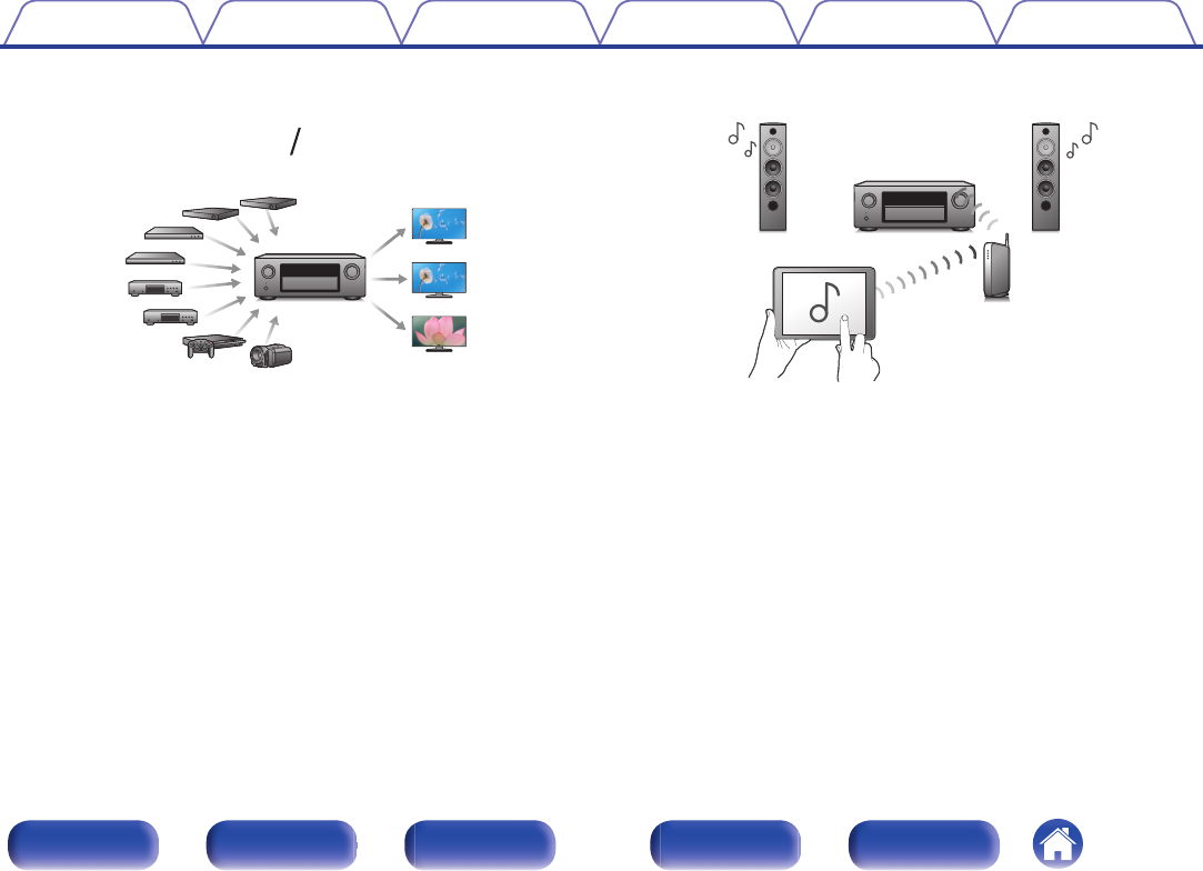
Easy to use Graphical User Interface
This unit is equipped with a Graphical User Interface for improved
operability.
ContentsConnectionsPlaybackSettingsTipsAppendix
17
Front panelDisplayRear panelRemoteIndex
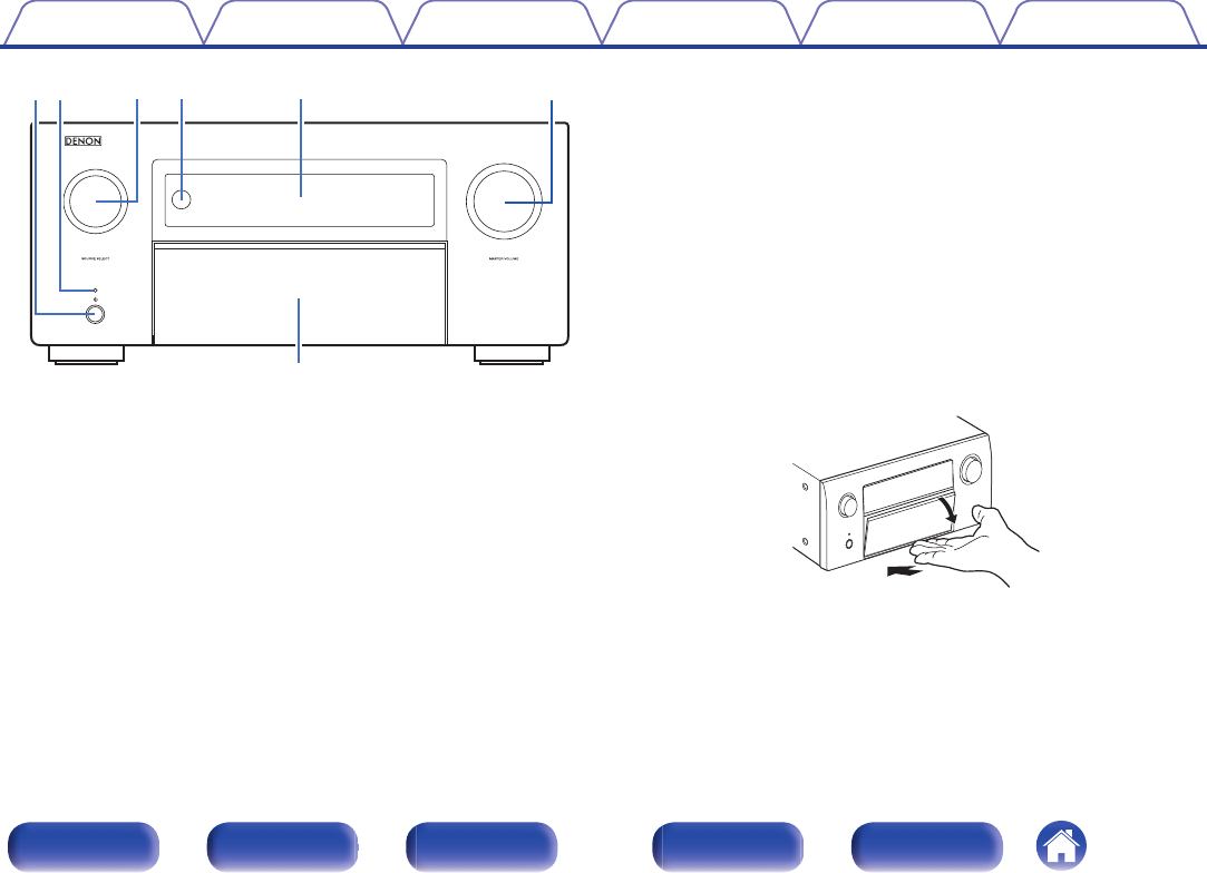
Part names and functions
Front panel
.
u
rwqeyt
For details, see the next page.
Contents
ConnectionsPlaybackSettingsTipsAppendix
18
Front panelDisplayRear panelRemoteIndex
.
u
wqrety
A
Power operation button (X)
Used to turn the power of the MAIN ZONE (room where this unit is
located) on/off (standby). (v p. 101)
B
Power indicator
This is lit as follows according to the power status:
0
Green: Power on
0
Off: Normal standby
0
Red:
0
When “HDMI Pass Through” is set to “On” (v p. 193)
0
When “HDMI Control” is set to “On” (v p. 195)
0
When “Network Control” is set to “Always On” (v p. 250)
C
SOURCE SELECT knob
This selects the input source. (v p. 101)
D
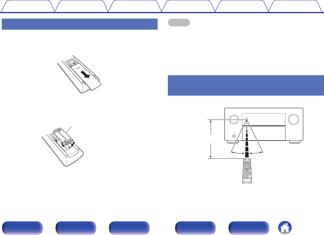
Remote control sensor
This receives signals from the remote control unit. (v p. 9)
E
Display
This displays various pieces of information. (v p. 22)
F
MASTER VOLUME knob
This adjusts the volume level. (v p. 102)
G
Door
When you are using buttons and/or connectors behind the door, press
the bottom of the door to open it. Be careful not to catch your fingers
when closing the door.
.
Contents
ConnectionsPlaybackSettingsTipsAppendix
19
Front panelDisplayRear panelRemoteIndex
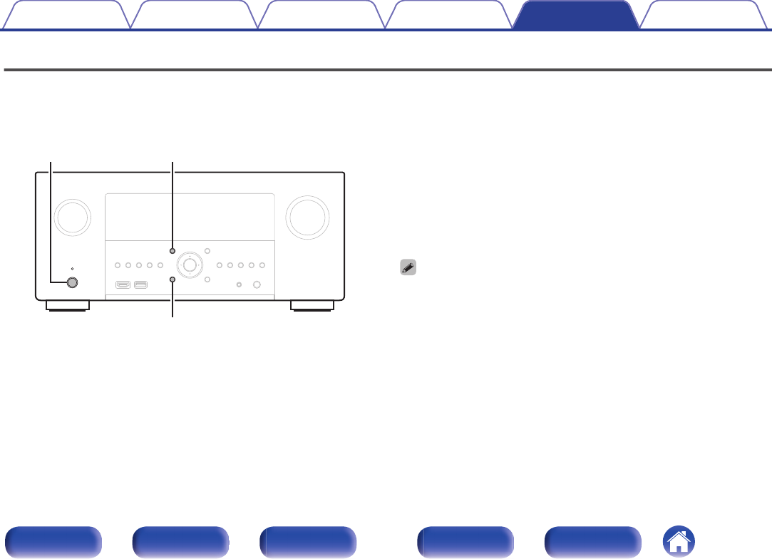
With the door open
.
ioQ0qwrtyue
A
ZONE2 ON/OFF button
This turns the power of ZONE2 (another room) on/off. (v p. 168)
B
ZONE2 SOURCE button
This selects the input source for ZONE2. (v p. 168)
C
ZONE3 ON/OFF button
This turns the power of ZONE3 (another room) on/off. (v p. 168)
D
ZONE3 SOURCE button
This selects the input source for ZONE3. (v p. 168)
E
STATUS button
Each press of this switches the status information that is shown on the
display.
F
Information button (INFO)
This displays the status information on the TV screen. (v p. 265)
G
Cursor buttons (uiop)
These select items.
H
OPTION button
This displays the option menu on the TV screen.
I
DIMMER button
Each press of this switches the brightness of the display. (v p. 260)
J
QUICK SELECT buttons
With a single press of any of these buttons, you can call up various
settings you’ve registered to each button such as the input source,
volume level and sound mode settings. (v p. 160)
Contents
ConnectionsPlaybackSettingsTipsAppendix
20
Front panelDisplayRear panelRemoteIndex
.
Q
6
Q
3
Q
7
Q
1
Q
2
Q
5
Q
4
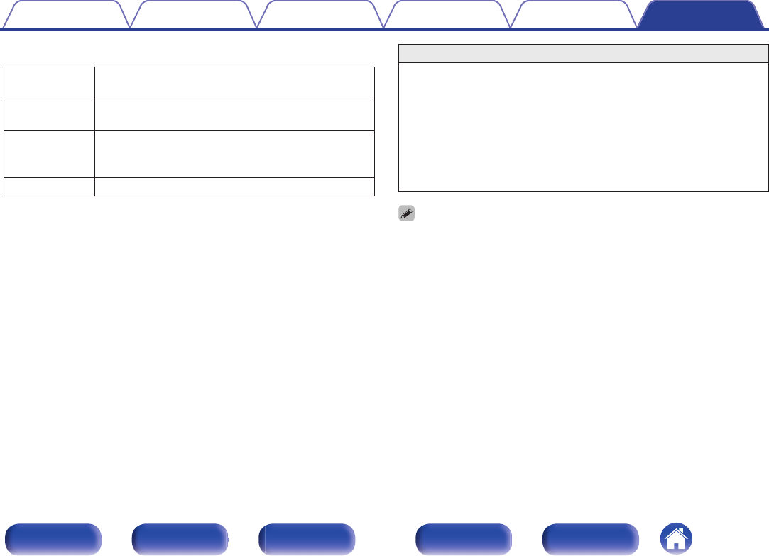
K
AUX1-HDMI connector
This is used to connect HDMI output compatible devices such as video
camcorders and game consoles. (v p. 91)
L
USB port (T)
This is used to connect USB storages (such as USB memory devices).
(v p. 94)
M
BACK button
This returns to the previous screen.
N
ENTER button
This determines the selection.
O
SETUP button
This displays the menu on the TV screen. (v p. 174)
P
SETUP MIC jack
This is used to connect the supplied Sound calibration microphone.
(v p. 214)
Q
Headphones jack (PHONES)
This is used to connect headphones.
When the headphones are plugged into this jack, audio will no longer
be output from the connected speakers or from the PRE OUT
connectors.
NOTE
0
To prevent hearing loss, do not raise the volume level excessively when using
headphones.
ContentsConnectionsPlaybackSettingsTipsAppendix
21
Front panelDisplayRear panelRemoteIndex
Display
.
oQ
0
Q
1
uyitr
ewq
A
Input signal indicators
The respective indicator will light corresponding to the input signal.
(v p. 210)
B
Decoder indicators
These light when Dolby or DTS signals are input or when the Dolby or
DTS decoder is running.
C
Audyssey
®
indicator
This lights when “MultEQ
®
XT32”, “Dynamic EQ”, “Dynamic Volume” or
“Audyssey LFC
TM
” has been set up. (v p. 186)
D
Monitor output indicator
These light according to the HDMI monitor output setting. When set to
“Auto(Dual)”, the indicators light according to connection status.
E
MULTI ZONE indicator
This lights up when ZONE2 or ZONE3 (another room) power is turned
on. (v p. 168)
Contents
ConnectionsPlaybackSettingsTipsAppendix
22
Front panelDisplayRear panelRemoteIndex
.
oQ0Q1
uyi
F
Sleep timer indicator
This lights when the sleep mode is selected. (v p. 158)
G
MUTE indicator
This blinks while the sound is muted. (v p. 102)
H
Volume indicator
I
Information display
The input source name, sound mode, setting values and other
information are displayed here.
J
Front speaker indicator
This lights according to the setting of the front A and B speakers.
K
Input/output signal channel indicators
The channel for input/output signals is displayed according to the
setting configured for “Channel Indicators”. (v p. 261)
0
When “Channel Indicators” is set to “Output” (Default)
These light when audio signals are being output from the speakers.
0
When “Channel Indicators” is set to “Input”
These light corresponding to the channels that include the input
signals.
When playing HD Audio sources, the A indicator lights when a
signal from an extension channel (a channel other than the front,
center, surround, surround back, front height, front wide or LFE
channel) is input.
ContentsConnectionsPlaybackSettingsTipsAppendix
23
Front panelDisplayRear panelRemoteIndex
Rear panel
.
1 CBL/SAT
PHONO
2 DVD
2
DVD
1
CBL/SAT
3 Blu-ray6 AUX27 CD
2
CD
1
TV
AUDIO
6 CD
4 GAME
5 MEDIA PLAYER
2 DVD
12
3 Blu-ray
5 MEDIAPLAYER
4 GAME
1
CBL/SAT
1
CBL/SAT
2 DVD
2 DVD3
Blu-ray
4 GAME
RS-232C
7.1CH IN
REMOTE CONTROL
TRIGGER OUT
PRE OUT
(ASSIGNABLE)
VIDEO
VIDEO
(ASSIGNABLE)(ASSIGNABLE)
COMPONENT VIDEO
COMPONENT VIDEO
ARC
MONITOR1
MONITOR
MONITOR/ZONE3
ZONE2
ZONE2
3 Blu-ray
MONITOR2
COAXIALOPTICAL
STRAIGHT CABLE
IR
DC12V 150mA MAX.
ZONE2ZONE3
FRONT
FRONT
SURROUND
CENTER
SUBWOOFER
SURROUND BACK
CENTER
SURROUND BACK
SURROUND
HEIGHT2
HEIGHT4/FRONT WIDE
1
AUDIO
(ASSIGNABLE)
AUDIO
DIGITAL AUDIO
(ASSIGNABLE)
2
ASSIGNABLEASSIGNABLE
ASSIGNABLEASSIGNABLE
ASSIGNABLE
1 CBL/SAT
Bluetooth
/
Wi-Fi
ANTENNA
Bluetooth
/
Wi-Fi
ANTENNA
AC IN
NETWORK
Y
P
B/
C
B
PR/
C
R
Denon Link HD
SPEAKERS
SUBWOOFER
HEIGHT1
HEIGHT3
POWER SUPPLY
5V/1.5A
FRONT
HEIGHT4/FRONT WIDE
HEIGHT3HEIGHT3
FRONT
CENTER
SURROUNDSURROUND
SURROUND BACKSURROUND BACK
HEIGHT1
HEIGHT1HEIGHT2HEIGHT2
HEIGHT4/FRONT WIDE
SIGNAL
GND
TUNER
AUDIO
etryiwuQ0Q1qq
Q
2
Q
7
Q
5
Q
6
Q
4
Q
3
o
For details, see the next page.
Contents
ConnectionsPlaybackSettingsTipsAppendix
24
Front panelDisplayRear panelRemoteIndex
.
1 CBL/SAT
PHONO
2 DVD
2
DVD
1
CBL/SAT
3 Blu-ray6 AUX27 CD
2
CD
1
TV
AUDIO
6 CD
4 GAME
5 MEDIA PLAYER
2 DVD
12
3 Blu-ray
5 MEDIAPLAYER
4 GAME
1
CBL/SAT
1
CBL/SAT
2 DVD
2 DVD3
Blu-ray
4 GAME
RS-232C
7.1CH IN
REMOTE CONTROL
TRIGGER OUT
PRE OUT
(ASSIGNABLE)
VIDEO
VIDEO
(ASSIGNABLE)(ASSIGNABLE)
COMPONENT VIDEO
COMPONENT VIDEO
ARC
MONITOR1
MONITOR
MONITOR/ZONE3
ZONE2
ZONE2
3 Blu-ray
MONITOR2
COAXIALOPTICAL
STRAIGHT CABLE
IR
DC12V 150mA MAX.
ZONE2ZONE3
FRONT
FRONT
SURROUND
CENTER
SUBWOOFER
SURROUND BACK
CENTER
SURROUND BACK
SURROUND
HEIGHT2
HEIGHT4/FRONT WIDE
1
AUDIO
(ASSIGNABLE)
AUDIO
DIGITAL AUDIO
(ASSIGNABLE)
2
ASSIGNABLEASSIGNABLE
ASSIGNABLEASSIGNABLE
ASSIGNABLE
1 CBL/SAT
Bluetooth
/
Wi-Fi
ANTENNA
Bluetooth
/
Wi-Fi
ANTENNA
AC IN
NETWORK
Y
P
B/
C
B
PR/
C
R
Denon Link HD
SPEAKERS
SUBWOOFER
HEIGHT1HEIGHT3
POWER SUPPLY
5V/1.5A
FRONT
HEIGHT4/FRONT WIDE
HEIGHT3HEIGHT3
FRONTCENTERSURROUNDSURROUND
SURROUND BACKSURROUND BACK
HEIGHT1HEIGHT1HEIGHT2HEIGHT2
HEIGHT4/FRONT WIDE
SIGNAL
GND
TUNER
AUDIO
etrwqq
y
A
Bluetooth/wireless LAN antenna connectors
Used to connect the included external antennas for Bluetooth/wireless
connectivity when connecting to a network via wireless LAN, or when
connecting to a handheld device via Bluetooth. (v p. 96)
A
Place the external antennas for Bluetooth/wireless connectivity
evenly over the screw terminal of rear.
B
Turn clockwise until the antennas is fully connected.
C
Rotate the antenna upwards for best reception.
.
qwe
1 CBL/SAT
PHONO
2 DVD
2
DVD
1
CBL/SAT
3 Blu-ray6 AUX27 CD
2
CD
1
TV
AUDIO
6 CD
4 GAME
5 MEDIA PLAYER
2 DVD
12
3 Blu-ray
5 MEDIAPLAYER
4 GAME
1
CBL/SAT
1
CBL/SAT
2 DVD
2 DVD3
Blu-ray
4 GAME
RS-232C
7.1CH IN
REMOTE CONTROL
TRIGGER OUT
PRE OUT
(ASSIGNABLE)
VIDEO
VIDEO
(ASSIGNABLE)(ASSIGNABLE)
COMPONENT VIDEO
COMPONENT VIDEO
ARC
MONITOR1
MONITOR
MONITOR/ZONE3
ZONE2
ZONE2
3 Blu-ray
MONITOR2
COAXIALOPTICAL
STRAIGHT CABLE
I
R
DC12V 150mA MAX.
ZONE2ZONE3
FRONT
FRONT
SURROUND
CENTER
SUBWOOFER
SURROUND BACK
CENTER
SURROUND BACK
SURROUND
HEIGHT2
HEIGHT4/FRONT WIDE
1
AUDIO
(ASSIGNABLE)
AUDIO
DIGITAL AUDIO
(ASSIGNABLE)
2
ASSIGNABLEASSIGNABLE
ASSIGNABLEASSIGNABLE
ASSIGNABLE
1 CBL/SAT
AC IN
NETWORK
Y
P
B/
C
B
PR/
C
R
Denon Link HD
SPEAKERS
SUBWOOFER
HEIGHT1
HEIGHT3
POWER SUPPLY
5V/1.5A
FRONT
HEIGHT4/FRONT WIDE
HEIGHT3HEIGHT3
FRONT
CENTER
SURROUNDSURROUND
SURROUND BACKSURROUND BACK
HEIGHT1HEIGHT1HEIGHT2HEIGHT2
HEIGHT4/FRONT WIDE
Bluetooth
/
Wi-Fi
ANTENNA
Bluetooth
/
Wi-Fi
ANTENNA
SIGNAL
GND
TUNER
AUDIO
B
Denon Link HD connector
Used to connect a Denon Link HD compatible Blu-ray Disc player.
(v p. 90)
C
USB port (POWER SUPPLY)
Can be used to power streaming media players, etc.
0
Use a device’s supplied AC adapter when a power supply of 5 V/1.5 A or more
is required.
0
Connect to the USB port on the front panel to play content from a USB
memory device.
D
Analog audio connectors (AUDIO)
Used to connect devices equipped with analog audio connectors.
0
“Connecting a set-top box (Satellite tuner/cable TV)” (v p. 88)
0
“Connecting a DVD player or Blu-ray Disc player” (v p. 89)
0
“Connecting a turntable” (v p. 92)
E
NETWORK connector
Used to connect to a LAN cable when connecting to a wired LAN
network. (v p. 95)
F
7.1-channel input connectors (7.1CH IN)
Used to connect to a device that has multi-channel audio output
connectors. (v p. 93)
Contents
ConnectionsPlaybackSettingsTipsAppendix
25
Front panelDisplayRear panelRemoteIndex
.
1 CBL/SAT
PHONO
2 DVD
2
DVD
1
CBL/SAT
3 Blu-ray6 AUX27 CD
2
CD
1
TV
AUDIO
6 CD
4 GAME
5 MEDIA PLAYER
2 DVD
12
3 Blu-ray
5 MEDIAPLAYER
4 GAME
1
CBL/SAT
1
CBL/SAT
2 DVD
2 DVD3
Blu-ray
4 GAME
RS-232C
7.1CH IN
REMOTE CONTROL
TRIGGER OUT
PRE OUT
(ASSIGNABLE)
VIDEO
VIDEO
(ASSIGNABLE)(ASSIGNABLE)
COMPONENT VIDEO
COMPONENT VIDEO
ARC
MONITOR1
MONITOR
MONITOR/ZONE3
ZONE2
ZONE2
3 Blu-ray
MONITOR2
COAXIALOPTICAL
STRAIGHT CABLE
IR
DC12V 150mA MAX.
ZONE2ZONE3
FRONT
FRONT
SURROUND
CENTER
SUBWOOFER
SURROUND BACK
CENTER
SURROUND BACK
SURROUND
HEIGHT2
HEIGHT4/FRONT WIDE
1
AUDIO
(ASSIGNABLE)
AUDIO
DIGITAL AUDIO
(ASSIGNABLE)
2
ASSIGNABLEASSIGNABLE
ASSIGNABLEASSIGNABLE
ASSIGNABLE
1 CBL/SAT
Bluetooth
/
Wi-Fi
ANTENNA
Bluetooth
/
Wi-Fi
ANTENNA
AC IN
NETWORK
Y
P
B/
C
B
PR/
C
R
Denon Link HD
SPEAKERS
SUBWOOFER
HEIGHT1HEIGHT3
POWER SUPPLY
5V/1.5A
FRONT
HEIGHT4/FRONT WIDE
HEIGHT3HEIGHT3
FRONTCENTERSURROUNDSURROUND
SURROUND BACKSURROUND BACK
HEIGHT1HEIGHT1HEIGHT2HEIGHT2
HEIGHT4/FRONT WIDE
SIGNAL
GND
TUNER
AUDIO
oiuQ0Q1
G
HDMI connectors
Used to connect devices equipped with HDMI connectors.
0
“Connection 1 : TV equipped with an HDMI connector and
compatible with the ARC (Audio Return Channel) / eARC (Enhanced
Audio Return Channel)” (v p. 83)
0
“Connection 2 : TV equipped with an HDMI connector and
incompatible with the ARC (Audio Return Channel) / eARC
(Enhanced Audio Return Channel)” (v p. 85)
0
“Connecting a set-top box (Satellite tuner/cable TV)” (v p. 88)
0
“Connecting a DVD player or Blu-ray Disc player” (v p. 89)
0
“Connecting a Blu-ray Disc player compatible with the Denon Link
HD function” (v p. 90)
H
PRE OUT connectors
Used to connect a subwoofer with built-in amplifier or an external power
amplifier.
0
“Connecting the subwoofer” (v p. 43)
0
“Connecting ZONE” (v p. 163)
I
Video connectors (VIDEO)
Used to connect devices equipped with video connectors.
0
“Connection 3 : TV equipped without an HDMI
connector” (v p. 86)
0
“Connecting a set-top box (Satellite tuner/cable TV)” (v p. 88)
0
“Connecting a DVD player or Blu-ray Disc player” (v p. 89)
J
Component video connectors (COMPONENT VIDEO)
Used to connect devices equipped with component video connectors.
0
“Connection 3 : TV equipped without an HDMI
connector” (v p. 86)
0
“Connecting a set-top box (Satellite tuner/cable TV)” (v p. 88)
0
“Connecting a DVD player or Blu-ray Disc player” (v p. 89)
K
AC inlet (AC IN)
Used to connect the power cord. (v p. 99)
Contents
ConnectionsPlaybackSettingsTipsAppendix
26
Front panelDisplayRear panelRemoteIndex
.
1 CBL/SAT
PHONO
2 DVD
2
DVD
1
CBL/SAT
3 Blu-ray6 AUX27 CD
2
CD
1
TV
AUDIO
6 CD
4 GAME
5 MEDIA PLAYER
2 DVD
12
3 Blu-ray
5 MEDIAPLAYER
4 GAME
1
CBL/SAT
1
CBL/SAT
2 DVD
2 DVD3
Blu-ray
4 GAME
RS-232C
7.1CH IN
REMOTE CONTROL
TRIGGER OUT
PRE OUT
(ASSIGNABLE)
VIDEO
VIDEO
(ASSIGNABLE)(ASSIGNABLE)
COMPONENT VIDEO
COMPONENT VIDEO
ARC
MONITOR1
MONITOR
MONITOR/ZONE3
ZONE2
ZONE2
3 Blu-ray
MONITOR2
COAXIALOPTICAL
STRAIGHT CABLE
IR
DC12V 150mA MAX.
ZONE2ZONE3
FRONT
FRONT
SURROUND
CENTER
SUBWOOFER
SURROUND BACK
CENTER
SURROUND BACK
SURROUND
HEIGHT2
HEIGHT4/FRONT WIDE
1
AUDIO
(ASSIGNABLE)
AUDIO
DIGITAL AUDIO
(ASSIGNABLE)
2
ASSIGNABLEASSIGNABLE
ASSIGNABLEASSIGNABLE
ASSIGNABLE
1 CBL/SAT
Bluetooth
/
Wi-Fi
ANTENNA
Bluetooth
/
Wi-Fi
ANTENNA
AC IN
NETWORK
Y
P
B/
C
B
PR/
C
R
Denon Link HD
SPEAKERS
SUBWOOFER
HEIGHT1HEIGHT3
POWER SUPPLY
5V/1.5A
FRONT
HEIGHT4/FRONT WIDE
HEIGHT3HEIGHT3
FRONTCENTERSURROUNDSURROUND
SURROUND BACKSURROUND BACK
HEIGHT1HEIGHT1HEIGHT2HEIGHT2
HEIGHT4/FRONT WIDE
SIGNAL
GND
TUNER
AUDIO
Q
7
Q
2
Q
5
Q
6
Q
4
Q
3
L
SIGNAL GND terminal
Used to connect a ground wire for the turntable. (v p. 92)
M
TRIGGER OUT jacks
Used to connect devices equipped with the trigger function.
(v p. 98)
N
REMOTE CONTROL jacks
Used to connect infrared receivers/transmitters in order to operate this
unit and external devices from a different room. (v p. 97)
O
RS-232C connector
Used to connect home automation controller devices fitted with
RS-232C connectors. Consult the owner’s manual of the home
automation controller for more information about serial control of this
unit.
Perform the operation below beforehand.
A
Turn on the power of this unit.
B
Turn off the power of this unit from the external controller.
C
Check that the unit is in the standby mode.
P
Digital audio connectors (DIGITAL AUDIO)
Used to connect devices equipped with digital audio connectors.
0
“Connection 2 : TV equipped with an HDMI connector and
incompatible with the ARC (Audio Return Channel) / eARC
(Enhanced Audio Return Channel)” (v p. 85)
0
“Connection 3 : TV equipped without an HDMI
connector” (v p. 86)
0
“Connecting a set-top box (Satellite tuner/cable TV)” (v p. 88)
0
“Connecting a DVD player or Blu-ray Disc player” (v p. 89)
Q
Speaker terminals (SPEAKERS)
Used to connect speakers. (v p. 42)
NOTE
0
Do not touch the inner pins of the connectors on the rear panel. Electrostatic
discharge may cause permanent damage to the unit.
ContentsConnectionsPlaybackSettingsTipsAppendix
27
Front panelDisplayRear panelRemoteIndex
Remote control unit
A
p indicator
This is lit when signals are sent from the remote control unit.
B
AVR operation button
When preset codes are registered to the remote control unit, press this
button and then operate the menu on the unit.
C
Zone select button (ZONE SELECT)
These switch the zone (MAIN ZONE, ZONE2, ZONE3) that is operated
through the remote control unit. (v p. 168, 174)
D
Display
A
Zone select indicators
B
Information indicator
0
This displays “AVR” when operating this unit.
0
This displays the input source name when operating an external
device.
0
This displays “TV” when operating TV.
0
This displays details about the setting on the remote control unit.
E
Device operation buttons (DEVICEX/DEVICE MENU)
These turn the power of external devices on/off and call up menus.
Preset codes need to be registered in order to use these buttons.
(v p. 268)
F
Input source select buttons
These select the input source.
0
“Selecting the input source” (v p. 101)
0
“Playback in ZONE2/ZONE3” (v p. 168)
e
w
q
r
t
y
qw
Contents
ConnectionsPlaybackSettingsTipsAppendix
28
Front panelDisplayRear panelRemoteIndex
G
QUICK SELECT buttons (1 – 4)
These call up settings registered to each button, such as input source,
volume level and sound mode settings. (v p. 160)
H
Channel/page search buttons (CH/PAGEdf)
These switch pages. (v p. 113)
I
MUTE button (:)
This mutes the output audio.
0
“Turning off the sound temporarily (Muting)” (v p. 102)
0
“Turning off the sound temporarily (Muting) (ZONE2/
ZONE3)” (v p. 169)
J
Information button (INFO)
This displays the status information on the TV screen. (v p. 265)
K
Cursor buttons (uiop)
These select items.
L
BACK button
This returns to the previous screen.
M
System buttons
These perform playback related operations.
i
o
u
Q3
Q2
Q1
Q0
Contents
ConnectionsPlaybackSettingsTipsAppendix
29
Front panelDisplayRear panelRemoteIndex
N
Number / Character buttons
These enter letters or numbers into the unit.
0
“Operating external devices with the remote control unit” (v p. 268)
O
Remote control signal transmitter
This transmits signals from the remote control unit. (v p. 9)
P
POWER button (X)
This turns the power on/off.
0
“Turning the power on” (v p. 101)
0
“Playback in ZONE2/ZONE3” (v p. 168)
Q
TV operation buttons (TVX/TV MENU/TV INPUT)
These turn the TV power on/off, switch the TV input and call up menus.
Preset codes need to be registered in order to use these buttons.
(v p. 273)
R
ECO Mode button (G)
This switches to ECO Mode. (v p. 253)
S
VOLUME buttons (df)
These adjust the volume level.
0
“Adjusting the volume” (v p. 102)
0
“Adjusting the volume (ZONE2/ZONE3)” (v p. 169)
T
OPTION button
This displays the option menu on the TV screen.
U
ENTER button
This determines the selection.
Q7
Q5
Q6
W0
Q8
Q9
W1
W1
Q4
Contents
ConnectionsPlaybackSettingsTipsAppendix
30
Front panelDisplayRear panelRemoteIndex
V
SETUP button
This displays the menu on the TV screen. (v p. 174)
W
SOUND MODE buttons
These select the sound mode. (v p. 140)
X
SLEEP button
This sets the sleep timer. (v p. 158)
Y
RC SETUP button
This used to set up the remote control unit. (v p. 268 – 284)
Z
MACRO buttons (A – D)
These are used to turn on a TV or player, and consecutive series of
operations can be registered to each button. (v p. 278)
W3
W5
W2
W4
W6
ContentsConnectionsPlaybackSettingsTipsAppendix
31
Front panelDisplayRear panelRemoteIndex
o
Contents
Speaker installation33
Connecting speakers42
Connecting a TV82
Connecting a playback device87
Connecting a USB memory device to the USB port94
Connecting to a home network (LAN)95
Connecting an external control device97
Connecting the power cord99
NOTE
0
Do not plug in the power cord until all connections have been completed.
However, when the “Setup Assistant” is running, follow the instructions in the
“Setup Assistant” (page 9 in the separate “Quick Start Guide”) screen for making
connections. (During “Setup Assistant” operation, the input/output connectors do
not conduct current.)
0
Do not bundle power cords together with connection cables. Doing so can result in
noise.
o
Cables used for connections
Provide necessary cables according to the devices you want to
connect.
Speaker cable
.
Subwoofer cable
.
HDMI cable
.
Component video cable
.
Video cable
.
Coaxial digital cable
.
Optical cable
.
Audio cable
.
R
L
R
L
LAN cable
.
ContentsConnectionsPlaybackSettingsTipsAppendix
32
Front panelDisplayRear panelRemoteIndex
Speaker installation
Determine the speaker system depending on the number of speakers you
are using and install each speaker and subwoofer in the room.
Speaker installation is explained using this example of a typical
installation.
.
C
FLFR
SBL
SBR
SB
SW1
SW2
FWL
FWR
SLSR
FL/FR
(Front speaker left/
right):
Place the FRONT left and right speakers an
equal distance from the main listening position.
The distance between each speaker and your TV
should also be the same.
C
(Center speaker):
Place the CENTER speaker in between the front
speakers and above or below your TV.
SL/SR
(Surround speaker left/
right):
Place the SURROUND left and right speakers an
equal distance to the left and right sides of the
main listening position. If you don’t have
surround back speakers, move the surround
speakers slightly behind your listening position.
SBL/SBR
(Surround back
speaker left/right):
Place the SURROUND BACK left and right
speakers an equal distance from the main
listening position and directly behind the main
listening position. When using a single surround
back speaker (SB), place it directly behind the
listening position.
FWL/FWR
(Front wide speaker
left/right):
Place the FRONT WIDE left and right speakers
outside of the front left and right speakers so that
there is an equal distance between all front
speakers.
SW 1/2
(Subwoofer):
Place the SUBWOOFER at a convenient location
near the front speakers. If you have two
subwoofers, place them asymmetrically across
the front of your room.
ContentsConnectionsPlaybackSettingsTipsAppendix
33
Front panelDisplayRear panelRemoteIndex
.
FHLFHR
TRR
TRL
TFR
TFL
RHLRHR
TMR
TML
FHL/FHR
(Front height speaker
left/right):
Place the FRONT HEIGHT left and right speakers
directly above the front speakers. Mount them as
close to the ceiling as possible and aim them
towards the main listening position.
TFL/TFR
(Top front speaker
left/right):
Mount the TOP FRONT left and right speakers on
the ceiling slightly in front of your main listening
position and aligned with the left and right front
speakers.
TML/TMR
(Top middle speaker
left/right):
Mount the TOP MIDDLE left and right speakers
directly above the main listening position and
aligned with the left and right front speakers.
TRL/TRR
(Top rear speaker
left/right):
Mount the TOP REAR left and right speakers on
the ceiling slightly behind your main listening
position and aligned with the left and right front
speakers.
RHL/RHR
(Rear height speaker
left/right):
Place the REAR HEIGHT left and right speakers
directly behind the main listening position. Mount
them as close to the ceiling as possible and
aligned with the left and right front speakers.
ContentsConnectionsPlaybackSettingsTipsAppendix
34
Front panelDisplayRear panelRemoteIndex
.
SHL
SHR
TS
CH
SHL/SHR
(Surround height
speaker left/right):
Place the SURROUND HEIGHT left and right
speakers directly above the surround speakers.
CH
(Center height
speaker):
Place the CENTER HEIGHT speaker directly
above the center speaker. Mount them as close to
the ceiling as possible and aim them towards the
main listening position.
TS
(Top surround
speaker):
Place the TOP SURROUND speaker directly
above the main listening position and aligned with
the center channel speaker.
0
For the best Auro-3D experience Surround Height speakers are recommended,
however you may substitute Rear Height speakers from a Dolby Atmos speaker
setup in place of Surround Height speakers.
ContentsConnectionsPlaybackSettingsTipsAppendix
35
Front panelDisplayRear panelRemoteIndex
.
FDLFDR
BDLBDR
SDLSDR
FDL/FDR
(Front Dolby speaker
left/right):
Place the FRONT Dolby Atmos Enabled speaker
on the front speaker. For a Dolby Atmos Enabled
integrated with a front speaker, place the Dolby
Atmos Enabled speaker instead of the front
speaker.
SDL/SDR
(Surround Dolby
speaker left/right):
Place the SURROUND Dolby Atmos Enabled
speaker on the surround speaker. For a Dolby
Atmos Enabled speaker integrated with a surround
speaker, place the Dolby Atmos Enabled speaker
instead of the surround speaker.
BDL/BDR
(Back Dolby speaker
left/right):
Place the BACK Dolby Atmos Enabled speaker on
the surround back speaker. For a Dolby Atmos
Enabled speaker integrated with a surround back
speaker, place the Dolby Atmos Enabled speaker
instead of the surround back speaker.
About Dolby Atmos Enabled speakers
Dolby Atmos Enabled speakers reflect the sound off the ceiling to allow
the sound to come from over your head by using a special upward-
pointing speaker that is placed on the floor.
You can enjoy the Dolby Atmos 3D sound even in an environment where
speakers cannot be installed on the ceiling.
.
Contents
ConnectionsPlaybackSettingsTipsAppendix
36
Front panelDisplayRear panelRemoteIndex
0
This unit is compatible with Dolby Atmos and DTS:X which offers an even wider
and deeper surround sensation.
0
Dolby Atmos is not supported in a 5.1-channel or less speaker configuration.
0
IMAX DTS:X / DTS:X can be selected regardless of the speaker configuration.
0
Auro-3D recommends adding FRONT HEIGHT and SURROUND HEIGHT
speakers to a 5.1 speaker configuration. Optionally, you may substitute REAR
HEIGHT, Dolby Atmos Enabled speakers instead of FRONT HEIGHT and
SURROUND HEIGHT speakers for Dolby Atmos, DTS:X and Auro-3D playback.
0
Use the illustration below as a guide for how high each speaker should be
installed. The height does not need to be exactly the same.
.
z
1
z2
z3
z4
z5
Point slightly
downwards
z1 30° - 45°
z4 125° - 150°
z2 30° - 55°
z3 65° - 100°
z5 135° - 150°
GViewed from the sideH
Top front speakerTop rear speaker
Front speaker
Surround
speaker
Surround
back
speaker
Point slightly
downwards
Rear height
speaker
Top middle / Top surround speakerSurround height speaker
Front height /
Center height
speaker
Front wide
speaker
.
TS
SL
TRL
RHLRHR
FHL
TML
TFL
FL
SR
TRR
FHRCH
TMR
TFR
FR
C
Height speakers layout
GViewed from the topH
SHRSHL
0
For the best Auro-3D experience Surround Height speakers are recommended,
however you may substitute Rear Height speakers from a Dolby Atmos speaker
setup in place of Surround Height speakers.
ContentsConnectionsPlaybackSettingsTipsAppendix
37
Front panelDisplayRear panelRemoteIndex
o
When 7.1-channel speakers are installed using
surround back speakers
.
z1
z2
z3
FL
SW
C
SL
SBL
FR
SR
SBR
Listening
position
z1 22° - 30°z2 90° - 110°z3 135° - 150°
0
When using a single surround back speaker, place it directly behind the listening
position.
o
When 9.1-channel speakers are installed using
front wide speakers
.
z3
z2
z1
z4
SBL
SBR
FL
SW
C
SL
FR
SR
FWL
FWR
z
1 22° - 30°
z
2 50° - 70°
z
3 90° - 110°
z
4 135° - 150°
Contents
ConnectionsPlaybackSettingsTipsAppendix
38
Front panelDisplayRear panelRemoteIndex
o
When 5.1-channel speakers are installed
.
z1
z2
FL
SW
C
SL
FR
SR
z1 22° - 30°z2 120°
o
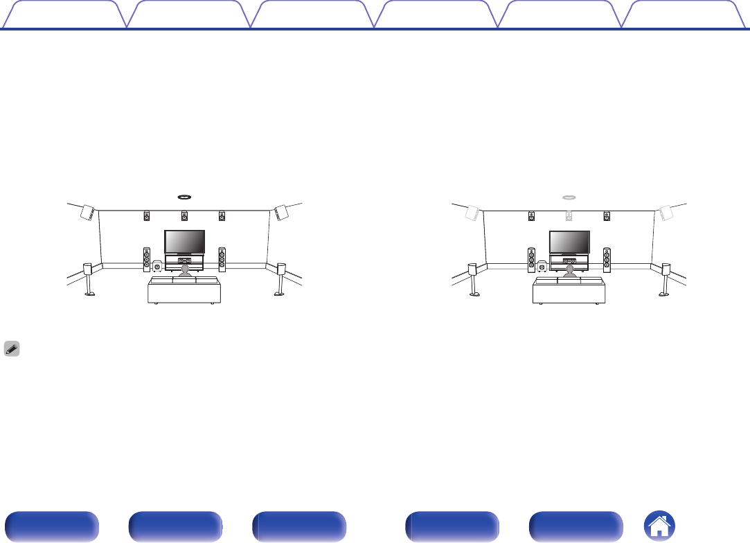
Layout including height speakers and ceiling
speakers
n
Height speaker layout example
Combination of 5.1-channel layout and front height/rear height/center
height speakers.
.
FHLFHR
C
FLFR
SW
SLSR
RHLRHR
Contents
ConnectionsPlaybackSettingsTipsAppendix
39
Front panelDisplayRear panelRemoteIndex
n
Ceiling speaker layout example
Combination of 5.1-channel layout and top front/top middle/top rear
speakers.
.
TRR
TRL
TFR
TFL
TMR
TML
C
FLFR
SW
SLSR
n
Dolby Atmos Enabled speaker layout example
Combination of 7.1-channel layout and front Dolby/surround Dolby/
back Dolby speakers.
.
C
FLFR
FDLFDR
SW
SLSR
SDLSDR
SBL
SBR
BDLBDR
Contents
ConnectionsPlaybackSettingsTipsAppendix
40
Front panelDisplayRear panelRemoteIndex
n
Auro-3D layout example
Combination of 5.1-channel speakers with front height/surround height/
center height/top surround speakers.
.
FHLFHR
SHL
SHR
TS
FLFR
SW
SLSR
C
CH
0
For the best Auro-3D experience Surround Height speakers are recommended,
however you may substitute Rear Height speakers from a Dolby Atmos speaker
setup in place of Surround Height speakers.
ContentsConnectionsPlaybackSettingsTipsAppendix
41
Front panelDisplayRear panelRemoteIndex
Connecting speakers
Here we connect the speakers in the room to this unit.
Before connecting speakers
NOTE
0
Disconnect this unit’s power plug from the power outlet before connecting the
speakers. Also, turn off the subwoofer.
0
Connect so that the speaker cable core wires do not protrude from the speaker
terminal. The protection circuit may be activated if the core wires touch the rear
panel or if the + and - sides touch each other. (“Protection circuit” (v p. 337))
0
Never touch the speaker terminals while the power cord is connected. Doing so
could result in electric shock. When the “Setup Assistant” (page 9 in the separate
“Quick Start Guide”) is running, follow the instructions in the “Setup Assistant”
screen for making connections. (Power is not supplied to the speaker terminals
while the “Setup Assistant” is running.)
0
Use speakers with an impedance of 4 – 16 Ω/ohms.
NOTE
0
Carry out the following settings when using a speaker with an impedance of 4 – 6
Ω/ohms.
1.Press and hold the main unit’s STATUS and ZONE3 SOURCE at the same
time for at least 3 seconds.
“zVideo Format < PAL>” appears on the display.
2.
Use u or i on the main unit three times.
“zSp. Impedance <8ohms>” appears on the display.
3.
Use o or p on the main unit to select the impedance.
8ohms
(Default):
Select when the impedance for all of the
connected speakers is 8 Ω/ohms or over.
6ohms:
Select when the impedance for any of the
connected speakers is 6 Ω/ohms.
4ohms:
Select when the impedance for any of the
connected speakers is 4 Ω/ohms.
4.Press the main unit’s ENTER to complete the setting.
Contents
ConnectionsPlaybackSettingsTipsAppendix
42
Front panelDisplayRear panelRemoteIndex
o
Connecting the speaker cables
Carefully check the left (L) and right (R) channels and + (red) and –
(black) polarities on the speakers being connected to this unit, and be
sure to connect the channels and polarities correctly.
1
Peel off about 10 mm of sheathing from the tip of the
speaker cable, then either twist the core wire tightly or
terminate it.
.
2
Turn the speaker terminal counterclockwise to loosen it.
.
3
Insert the speaker cable’s core wire to the hilt into the
speaker terminal.
.
4
Turn the speaker terminal clockwise to tighten it.
.
o
Connecting the subwoofer
Use a subwoofer cable to connect the subwoofer. Two subwoofers can
be connected to this unit.
To use two subwoofers, set “Subwoofer” to “2 spkrs” in the “Speaker
Config.” setting. (v p. 232)
The level and distance can be set separately for Subwoofer 1 and
Subwoofer 2.
.
1 CBL/SAT
PHONO
2
DVD
1
CBL/SAT
2
CD
1
TV
AUDIO
6 CD
2 DVD
12
3 Blu-ray
5 MEDIAPLAYER
4 GAME
RS-232C
7.1CH IN
REMOTE CONTROL
TRIGGER OUT
PRE OUT
COAXIALOPTICAL
STRAIGHT CABLE
I
R
DC12V 150mA MAX.
ZONE2ZONE3
FRONT
FRONT
SURROUND
CENTER
SUBWOOFER
SURROUND BACK
CENTER
SURROUND BACK
SURROUND
HEIGHT2
HEIGHT4/FRONT WIDE
1
AUDIO
(ASSIGNABLE)
AUDIO
DIGITAL AUDIO
(ASSIGNABLE)
2
ASSIGNABLEASSIGNABLE
ASSIGNABLEASSIGNABLE
ASSIGNABLE
SPEAKERS
SUBWOOFER
HEIGHT1
HEIGHT3
FRONT
HEIGHT4/FRONT WIDE
HEIGHT3HEIGHT3
FRONT
CENTER
SURROUNDSURROUND
SURROUND BACKSURROUND BACK
HEIGHT1HEIGHT1HEIGHT2HEIGHT2
HEIGHT4/FRONT WIDE
SW1SW2
Contents
ConnectionsPlaybackSettingsTipsAppendix
43
Front panelDisplayRear panelRemoteIndex
o
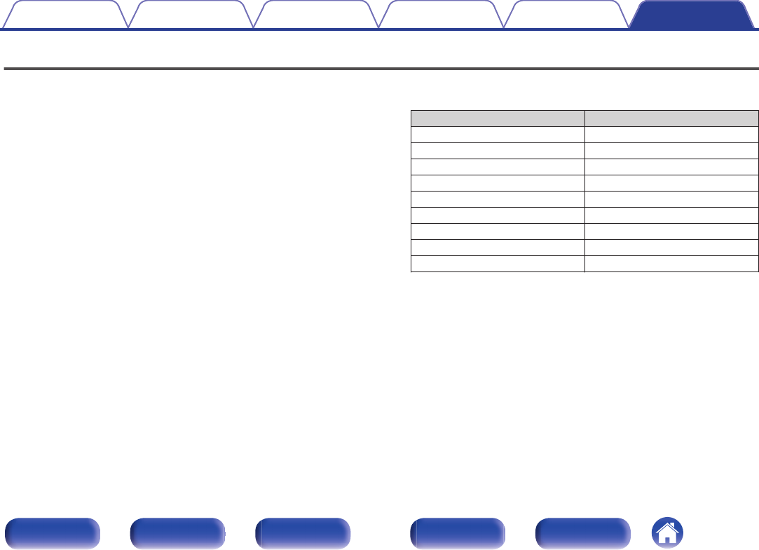
About the cable labels (supplied) for channel identification
The channel display section for speaker terminals on the rear panel is color-coded for each channel to be identifiable.
Attach the cable label corresponding to each speaker to each speaker cable.
This makes it easy to connect the correct cable to the speaker terminals on the rear panel.
SpeakerColor
FRONT LWhite
FRONT RRed
CENTERGreen
SURROUND LLight Blue
SURROUND RBlue
SURROUND BACK LBeige
SURROUND BACK RBrown
FRONT WIDE LGlass Green
FRONT WIDE ROlive Green
FRONT HEIGHT LLight Yellow
FRONT HEIGHT RYellow
TOP FRONT LLight Yellow
TOP FRONT RYellow
TOP MIDDLE LPink
TOP MIDDLE RMagenta
TOP REAR LLight Purple
TOP REAR RPurple
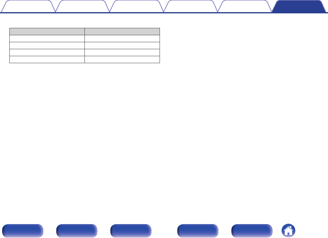
SpeakerColor
SURROUND HEIGHT LPink
SURROUND HEIGHT RMagenta
REAR HEIGHT LLight Purple
REAR HEIGHT RPurple
TOP SURROUNDGlass Green
CENTER HEIGHTOlive Green
FRONT DOLBY LLight Yellow
FRONT DOLBY RYellow
SURROUND DOLBY LPink
SURROUND DOLBY RMagenta
BACK DOLBY LLight Purple
BACK DOLBY RPurple
SUBWOOFER 1Black
SUBWOOFER 2Black
ContentsConnectionsPlaybackSettingsTipsAppendix
44
Front panelDisplayRear panelRemoteIndex
Attach the cable label for each channel to its speaker cable as shown
in the diagram.
Refer to the table and attach the label to each speaker cable.
Then, make connection so that the color of the speaker terminal
matches that of the cable label.
GHow to attach the cable labelsH
.
Speaker
This unit
ContentsConnectionsPlaybackSettingsTipsAppendix
45
Front panelDisplayRear panelRemoteIndex
Speaker configuration and “Amp Assign” settings
This unit has a built-in 13-channel power amplifier. In addition to the basic 5.1-channel system, a variety of speaker systems can be configured by
changing the “Amp Assign” settings to suit the application, such as 7.1-channel systems, bi-amp connections and 2-channel systems for multi-zone
playback. (v p. 222)
Perform “Amp Assign” settings to suit the number of rooms and speaker configuration to be installed. (v p. 222)
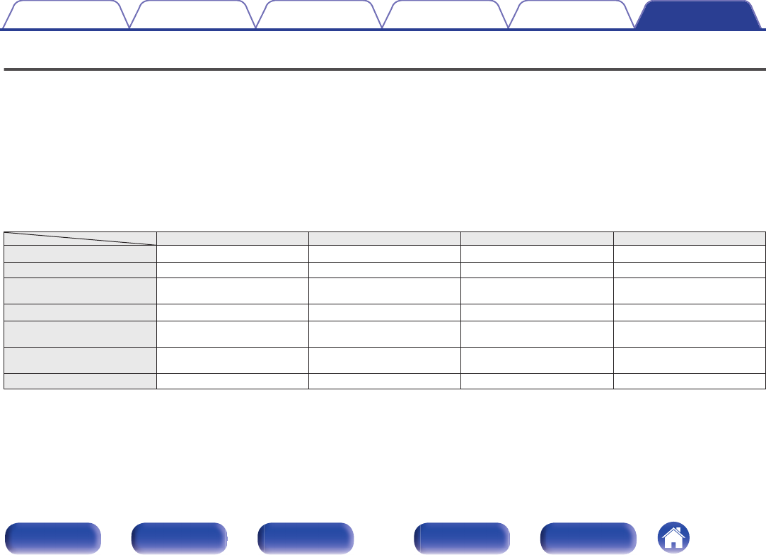
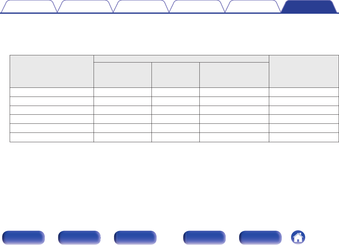
Playback speaker in each zone
“Amp Assign” settings
Connection
page
MAIN ZONEZONE2ZONE3
5.1-channel playback
2-channel (Pre-out)2-channel (Pre-out)
Can be set in all “Amp
Assign” modes.
48
7.1-channel playbackCan be set in all “Amp
Assign” modes except for
“5.1ch Full Bi-Amp”.
49
9.1-channel playback54
13.1-channel playback13.1ch63
13.1-channel playback (Dolby Atmos and Auro-3D)13.1ch (Default)68
11.1-channel playback (bi-amp connection of front
speakers)
11.1ch (Bi-Amp)74
5.1-channel playback (bi-amp connection of front, center
and surround speakers)
5.1ch Full Bi-Amp75
Second front speakers11.1ch + Front B76
11.1-channel playback2-channel
(Speaker out)
2-channel (Pre-out)11.1ch + ZONE277
11.1-channel playback2-channel (Pre-out)2-channel
(Speaker out)
11.1ch + ZONE377
9.1-channel playback (bi-amp connection of front
speakers)
2-channel
(Speaker out)
2-channel (Pre-out)9.1ch (Bi-Amp) + ZONE278
9.1-channel playback2-channel
(Speaker out)
2-channel
(Speaker out)
9.1ch + ZONE2/379
11.1-channel playback1-channel
(Speaker out)
1-channel
(Speaker out)
11.1ch + ZONE2/3-MONO80
13.1-channel playback (using this unit as a pre amplifier)Not usedNot usedPre Amplifier81
The sound mode that can be selected varies according to the speaker configuration. See “Sound modes and channel output” (v p. 319) for the sound
modes that are supported.
The following pages provide basic connection examples.
Contents
ConnectionsPlaybackSettingsTipsAppendix
46
Front panelDisplayRear panelRemoteIndex
Refer to the example connection for “Example connection for the Auro-3D
9.1-channel system” (v p. 61) when playing Auro-3D with a 9.1-
channel system using the basic 5.1-channel system and the front height
and surround height speakers.
Also refer to the connection example for “Example connection for the
Auro-3D 13.1-channel system” (v p. 67) when playing Auro-3D with a
13.1-channel system by adding the Surround Back, Top Surround and
Center Height speakers.
0
In addition to the connections described in
p.48 - 80, this unit allows for various
speaker connections with the “Amp Assign” setting.
Also refer to the menu screen in “View Terminal Config.” on the “Amp Assign”
setting screen, which shows how to make connections in your environment.
.
CENTERSURROUNDSURROUNDFRONTFRONTCENTERSURROUND
SURR.BACK
SURROUNDFRONT
SURR. BACK
FRONTHEIGHT1HEIGHT1HEIGHT1HEIGHT1
F.HEIGHTR.HEIGHTSURR.BACKSURROUNDCENTERFRONT
HEIGHT2
HEIGHT2
SUBWOOFER
12
SUBWOOFER
SPEAKERS
Speakers/Amp Assign
PRE OUT
Assign Mode13.1ch
Back
T.MIDDLEC.HEIGHTT.SURROUND
HEIGHT4HEIGHT3HEIGHT3HEIGHT4
Contents
ConnectionsPlaybackSettingsTipsAppendix
47
Front panelDisplayRear panelRemoteIndex
Connecting 5.1-channel speakers
This serves as a basic 5.1-channel surround system.
.
FL
SWC
SL
FR
SR
.
1 CBL/SAT
PHONO
2
DVD
1
CBL/SAT
2
CD
1
TV
AUDIO
6 CD
2 DVD
12
3 Blu-ray
5 MEDIAPLAYER
4 GAME
RS-232C
7.1CH IN
REMOTE CONTROL
TRIGGER OUT
PRE OUT
COAXIALOPTICAL
STRAIGHT CABLE
I
R
DC12V 150mA MAX.
ZONE2ZONE3
FRONT
FRONT
SURROUND
CENTER
SUBWOOFER
SURROUND BACK
CENTER
SURROUND BACK
SURROUND
HEIGHT2
HEIGHT4/FRONT WIDE
1
AUDIO
(ASSIGNABLE)
AUDIO
DIGITAL AUDIO
(ASSIGNABLE)
2
ASSIGNABLEAS SIGNABLE
ASSIGNABLEAS SIGNABLE
ASSIGNABLE
SPEAKERS
SUBWOOFER
HEIGHT1
HEIGHT3
HEIGHT4/FRONT WIDE
HEIGHT3HEIGHT3
SURROUND BACKSURROUND BACK
HEIGHT1HEIGHT1HEIGHT2HEIGHT2
HEIGHT4/FRONT WIDE
FRONTFRONT
CENTER
SURROUNDSURROUND
SW
FRFLCSRSL
ContentsConnectionsPlaybackSettingsTipsAppendix
48
Front panelDisplayRear panelRemoteIndex
Connecting 7.1-channel speakers
o
Example connections when using surround back speakers
This 7.1-channel surround system is the same as a basic 5.1-channel system but with surround back speakers.
.
FL
SWC
SL
FR
SR
SBRSBL
0
Set “Floor” - “Layout” to “5ch & SB” in the menu when connecting in this
configuration. (v p. 225)
.
1 CBL/SAT
PHONO
2
DVD
1
CBL/SAT
2
CD
1
TV
AUDIO
6 CD
2 DVD
12
3 Blu-ray
5 MEDIAPLAYER
4 GAME
RS-232C
7.1CH IN
REMOTE CONTROL
TRIGGER OUT
PRE OUT
COAXIALOPTICAL
STRAIGHT CABLE
I
R
DC12V 150mA MAX.
ZONE2ZONE3
FRONT
FRONT
SURROUND
CENTER
SUBWOOFER
SURROUND BACK
CENTER
SURROUND BACK
SURROUND
HEIGHT2
HEIGHT4/FRONT WIDE
1
AUDIO
(ASSIGNABLE)
AUDIO
DIGITAL AUDIO
(ASSIGNABLE)
2
SUBWOOFER
HEIGHT1
HEIGHT3
ASSIGNABLE
SPEAKERS
FRONTFRONT
CENTER
SURROUNDSURROUND
SURROUND BACKSURROUND BACK
ASSIGNABLE
ASSIGNABLEAS SIGNABLE
ASSIGNABLE
HEIGHT4/FRONT WIDE
HEIGHT3HEIGHT3
HEIGHT1HEIGHT1HEIGHT2HEIGHT2
HEIGHT4/FRONT WIDE
SBRSBL
SW
FRFLCSRSL
0
When using a single surround back speaker, connect it to the SURROUND BACK
L terminal.
ContentsConnectionsPlaybackSettingsTipsAppendix
49
Front panelDisplayRear panelRemoteIndex
o
Example connections when using front wide speakers
This 7.1-channel surround system is the same as a basic 5.1-channel system but with front wide speakers.
.
FL
SWC
SL
FR
SR
FWLFWR
.
1 CBL/SAT
PHONO
2
DVD
1
CBL/SAT
2
CD
1
TV
AUDIO
6 CD
2 DVD
12
3 Blu-ray
5 MEDIAPLAYER
4 GAME
RS-232C
7.1CH IN
REMOTE CONTROL
TRIGGER OUT
PRE OUT
COAXIALOPTICAL
STRAIGHT CABLE
I
R
DC12V 150mA MAX.
ZONE2ZONE3
FRONT
FRONT
SURROUND
CENTER
SUBWOOFER
SURROUND BACK
CENTER
SURROUND BACK
SURROUND
HEIGHT2
HEIGHT4/FRONT WIDE
1
AUDIO
(ASSIGNABLE)
AUDIO
DIGITAL AUDIO
(ASSIGNABLE)
2
ASSIGNABLEAS SIGNABLE
ASSIGNABLE
ASSIGNABLE
SPEAKERS
SUBWOOFER
HEIGHT1
HEIGHT3
HEIGHT3HEIGHT3
SURROUND BACKSURROUND BACK
HEIGHT1HEIGHT1HEIGHT2HEIGHT2
FRONTFRONT
CENTER
SURROUNDSURROUND
ASSIGNABLE
HEIGHT4/FRONT WIDE
HEIGHT4/FRONT WIDE
SW
FRFLCSRSL
FWRFWL
0
Set “Floor” - “Layout” to “5ch & FW” in the menu when connecting in this configuration. (v p. 225)
ContentsConnectionsPlaybackSettingsTipsAppendix
50
Front panelDisplayRear panelRemoteIndex
o
Example connections when using ceiling speakers
This 7.1-channel surround system is the same as a basic 5.1-channel system but with ceiling speakers.
.
C
FLFR
SW
SLSR
TMLTMR
.
1 CBL/SAT
PHONO
2
DVD
1
CBL/SAT
2
CD
1
TV
AUDIO
6 CD
2 DVD
12
3 Blu-ray
5 MEDIAPLAYER
4 GAME
RS-232C
7.1CH IN
REMOTE CONTROL
TRIGGER OUT
PRE OUT
COAXIALOPTICAL
STRAIGHT CABLE
I
R
DC12V 150mA MAX.
ZONE2ZONE3
FRONT
FRONT
SURROUND
CENTER
SUBWOOFER
SURROUND BACK
CENTER
SURROUND BACK
SURROUND
HEIGHT2
HEIGHT4/FRONT WIDE
1
AUDIO
(ASSIGNABLE)
AUDIO
DIGITAL AUDIO
(ASSIGNABLE)
2
SUBWOOFER
HEIGHT1
HEIGHT3
ASSIGNABLE
SPEAKERS
FRONTFRONT
CENTER
SURROUNDSURROUND
HEIGHT1HEIGHT1
ASSIGNABLE
ASSIGNABLEAS SIGNABLE
ASSIGNABLE
HEIGHT4/FRONT WIDE
HEIGHT3HEIGHT3
SURROUND BACKSURROUND BACK
HEIGHT2HEIGHT2
HEIGHT4/FRONT WIDE
FRFLCSRSL
TMRTML
SW
0
Set “Floor” - “Layout” to “5ch” and “Height Sp” to “2ch” in the menu when connecting in this configuration. (v p. 225)
0
The top front or top rear speakers can be connected instead of the top middle speakers. In this case, set the ceiling speakers to be connected under “Height” - “Layout” in the
menu. (v p. 227)
ContentsConnectionsPlaybackSettingsTipsAppendix
51
Front panelDisplayRear panelRemoteIndex
o
Example connections when using height speakers
This 7.1-channel surround system is the same as a basic 5.1-channel system but with front height speakers.
.
FL
SWC
SL
FHR
FR
SR
FHL
.
1 CBL/SAT
PHONO
2
DVD
1
CBL/SAT
2
CD
1
TV
AUDIO
6 CD
2 DVD
12
3 Blu-ray
5 MEDIAPLAYER
4 GAME
RS-232C
7.1CH IN
REMOTE CONTROL
TRIGGER OUT
PRE OUT
COAXIALOPTICAL
STRAIGHT CABLE
I
R
DC12V 150mA MAX.
ZONE2ZONE3
FRONT
FRONT
SURROUND
CENTER
SUBWOOFER
SURROUND BACK
CENTER
SURROUND BACK
SURROUND
HEIGHT2
HEIGHT4/FRONT WIDE
1
AUDIO
(ASSIGNABLE)
AUDIO
DIGITAL AUDIO
(ASSIGNABLE)
2
SUBWOOFER
HEIGHT1
HEIGHT3
ASSIGNABLE
SPEAKERS
FRONTFRONT
CENTER
SURROUNDSURROUND
HEIGHT1HEIGHT1
ASSIGNABLE
ASSIGNABLEAS SIGNABLE
ASSIGNABLE
HEIGHT4/FRONT WIDE
HEIGHT3HEIGHT3
SURROUND BACKSURROUND BACK
HEIGHT2HEIGHT2
HEIGHT4/FRONT WIDE
FHRFHL
FRFLCSRSL
SW
0
Set “Floor” - “Layout” to “5ch” and “Height Sp” to “2ch” in the menu when connecting in this configuration. (v p. 225)
0
The rear height speakers can be connected instead of the front height speakers. In this case, set the height speakers to be connected under “Height” - “Layout” in the menu.
(v p. 227)
ContentsConnectionsPlaybackSettingsTipsAppendix
52
Front panelDisplayRear panelRemoteIndex
o
Example connections when using Dolby Atmos Enabled speakers
This 7.1-channel surround system is the same as a basic 5.1-channel system but with front Dolby speakers.
.
C
SWFLFR
SLSR
FDLFDR
.
1 CBL/SAT
PHONO
2
DVD
1
CBL/SAT
2
CD
1
TV
AUDIO
6 CD
2 DVD
12
3 Blu-ray
5 MEDIAPLAYER
4 GAME
RS-232C
7.1CH IN
REMOTE CONTROL
TRIGGER OUT
PRE OUT
COAXIALOPTICAL
STRAIGHT CABLE
I
R
DC12V 150mA MAX.
ZONE2ZONE3
FRONT
FRONT
SURROUND
CENTER
SUBWOOFER
SURROUND BACK
CENTER
SURROUND BACK
SURROUND
HEIGHT2
HEIGHT4/FRONT WIDE
1
AUDIO
(ASSIGNABLE)
AUDIO
DIGITAL AUDIO
(ASSIGNABLE)
2
SUBWOOFER
HEIGHT1
HEIGHT3
ASSIGNABLE
SPEAKERS
FRONTFRONT
CENTER
SURROUNDSURROUND
HEIGHT1HEIGHT1
ASSIGNABLE
ASSIGNABLEAS SIGNABLE
ASSIGNABLE
HEIGHT4/FRONT WIDE
HEIGHT3HEIGHT3
SURROUND BACKSURROUND BACK
HEIGHT2HEIGHT2
HEIGHT4/FRONT WIDE
FDRFDL
FRFLCSRSL
SW
0
Set “Floor” - “Layout” to “5ch” and “Dolby Sp” to “2ch” in the menu when connecting in this configuration. (v p. 225, 226)
0
The surround Dolby speakers can be connected instead of the front Dolby speakers. In this case, set the Dolby Atmos Enabled speakers to be connected under “Height” -
“Layout” in the menu. (v p. 227)
ContentsConnectionsPlaybackSettingsTipsAppendix
53
Front panelDisplayRear panelRemoteIndex
Connecting 9.1-channel speakers
o
Example connection when using surround back and front wide speakers
.
FL
SWC
SL
FR
SR
SBRSBL
FWLFWR
.
1 CBL/SAT
PHONO
2
DVD
1
CBL/SAT
2
CD
1
TV
AUDIO
6 CD
2 DVD
12
3 Blu-ray
5 MEDIAPLAYER
4 GAME
RS-232C
7.1CH IN
REMOTE CONTROL
TRIGGER OUT
PRE OUT
COAXIALOPTICAL
STRAIGHT CABLE
I
R
DC12V 150mA MAX.
ZONE2ZONE3
FRONT
FRONT
SURROUND
CENTER
SUBWOOFER
SURROUND BACK
CENTER
SURROUND BACK
SURROUND
HEIGHT2
HEIGHT4/FRONT WIDE
1
AUDIO
(ASSIGNABLE)
AUDIO
DIGITAL AUDIO
(ASSIGNABLE)
2
SUBWOOFER
HEIGHT1
HEIGHT3
ASSIGNABLE
SPEAKERS
FRONTFRONT
CENTER
SURROUNDSURROUND
SURROUND BACKSURROUND BACK
ASSIGNABLE
ASSIGNABLE
ASSIGNABLE
HEIGHT3HEIGHT3
HEIGHT1HEIGHT1HEIGHT2HEIGHT2
ASSIGNABLE
HEIGHT4/FRONT WIDE
HEIGHT4/FRONT WIDE
FWRFWL
SBRSBL
SW
FRFLCSRSL
0
Set “Floor” - “Layout” to “5ch & SB & FW” in the menu when connecting in this configuration. (v p. 225)
ContentsConnectionsPlaybackSettingsTipsAppendix
54
Front panelDisplayRear panelRemoteIndex
o
Example connection when using one set of ceiling speakers
.
C
FLFR
SBL
SBR
SW
SLSR
TMLTMR
0
Set “Floor” - “Layout” to “5ch & SB” and “Height Sp” to “2ch” in the menu when
connecting in this configuration. (v p. 225)
.
1 CBL/SAT
PHONO
2
DVD
1
CBL/SAT
2
CD
1
TV
AUDIO
6 CD
2 DVD
12
3 Blu-ray
5 MEDIAPLAYER
4 GAME
RS-232C
7.1CH IN
REMOTE CONTROL
TRIGGER OUT
PRE OUT
COAXIALOPTICAL
STRAIGHT CABLE
I
R
DC12V 150mA MAX.
ZONE2ZONE3
FRONT
FRONT
SURROUND
CENTER
SUBWOOFER
SURROUND BACK
CENTER
SURROUND BACK
SURROUND
HEIGHT2
HEIGHT4/FRONT WIDE
1
AUDIO
(ASSIGNABLE)
AUDIO
DIGITAL AUDIO
(ASSIGNABLE)
2
SUBWOOFER
HEIGHT1
HEIGHT3
ASSIGNABLEAS SIGNABLE
SPEAKERS
FRONTFRONT
CENTER
SURROUNDSURROUND
SURROUND BACKSURROUND BACK
HEIGHT1HEIGHT1
ASSIGNABLEAS SIGNABLE
ASSIGNABLE
HEIGHT4/FRONT WIDE
HEIGHT3HEIGHT3
HEIGHT2HEIGHT2
HEIGHT4/FRONT WIDE
TMRTML
HEIGHT 1
z
SW
SBRSBL
FRFLCSRSL
z
The top front or top rear speakers can be connected instead of the top middle
speakers. In this case, set the ceiling speakers to be connected under “Height” -
“Layout” in the menu. (v p. 227)
Contents
ConnectionsPlaybackSettingsTipsAppendix
55
Front panelDisplayRear panelRemoteIndex
o
Example connection when using two sets of ceiling speakers
.
C
FLFR
SW
SLSR
TRLTRR
TFLTFR
0
Set “Floor” - “Layout” to “5ch” and “Height Sp” to “4ch” in the menu when
connecting in this configuration. (v p. 225)
.
1 CBL/SAT
PHONO
2
DVD
1
CBL/SAT
2
CD
1
TV
AUDIO
6 CD
2 DVD
12
3 Blu-ray
5 MEDIAPLAYER
4 GAME
RS-232C
7.1CH IN
REMOTE CONTROL
TRIGGER OUT
PRE OUT
COAXIALOPTICAL
STRAIGHT CABLE
I
R
DC12V 150mA MAX.
ZONE2ZONE3
FRONT
FRONT
SURROUND
CENTER
SUBWOOFER
SURROUND BACK
CENTER
SURROUND BACK
SURROUND
HEIGHT2
HEIGHT4/FRONT WIDE
1
AUDIO
(ASSIGNABLE)
AUDIO
DIGITAL AUDIO
(ASSIGNABLE)
2
SUBWOOFER
HEIGHT1
HEIGHT3
ASSIGNABLEASSIGNABLE
SPEAKERS
FRONTFRONT
CENTER
SURROUNDSURROUND
HEIGHT1HEIGHT1HEIGHT2HEIGHT2
ASSIGNABLE
ASSIGNABLEASSIGNABLE
HEIGHT4/FRONT WIDE
HEIGHT3HEIGHT3
SURROUND BACKSURROUND BACK
HEIGHT4/FRONT WIDE
TRRTRLTFRTFL
HEIGHT 1
z
HEIGHT 2
z
SW
FRFLCSRSL
z
You can change the combination of the HEIGHT1 and HEIGHT2 channels in the
settings. (v p. 62)
Contents
ConnectionsPlaybackSettingsTipsAppendix
56
Front panelDisplayRear panelRemoteIndex
o
Example connection when using one set of height speakers
.
C
FLFR
SBL
SBR
SW
SLSR
FHLFHR
0
Set “Floor” - “Layout” to “5ch & SB” and “Height Sp” to “2ch” in the menu when
connecting in this configuration. (v p. 225)
.
1 CBL/SAT
PHONO
2
DVD
1
CBL/SAT
2
CD
1
TV
AUDIO
6 CD
2 DVD
12
3 Blu-ray
5 MEDIAPLAYER
4 GAME
RS-232C
7.1CH IN
REMOTE CONTROL
TRIGGER OUT
PRE OUT
COAXIALOPTICAL
STRAIGHT CABLE
I
R
DC12V 150mA MAX.
ZONE2ZONE3
FRONT
FRONT
SURROUND
CENTER
SUBWOOFER
SURROUND BACK
CENTER
SURROUND BACK
SURROUND
HEIGHT2
HEIGHT4/FRONT WIDE
1
AUDIO
(ASSIGNABLE)
AUDIO
DIGITAL AUDIO
(ASSIGNABLE)
2
SUBWOOFER
HEIGHT1
HEIGHT3
ASSIGNABLEAS SIGNABLE
SPEAKERS
FRONTFRONT
CENTER
SURROUNDSURROUND
SURROUND BACKSURROUND BACK
HEIGHT1HEIGHT1
ASSIGNABLEAS SIGNABLE
ASSIGNABLE
HEIGHT4/FRONT WIDE
HEIGHT3HEIGHT3
HEIGHT2HEIGHT2
HEIGHT4/FRONT WIDE
FHRFHL
HEIGHT 1
z
SW
SBRSBL
FRFLCSRSL
z
The rear height speakers can be connected instead of the front height speakers.
In this case, set the height speakers to be connected under “Height” - “Layout” in
the menu. (v p. 227)
Contents
ConnectionsPlaybackSettingsTipsAppendix
57
Front panelDisplayRear panelRemoteIndex
o
Example connection when using two sets of height speakers
.
C
FLFR
SW
SLSR
FHLFHR
RHLRHR
0
Set “Floor” - “Layout” to “5ch” and “Height Sp” to “4ch” in the menu when
connecting in this configuration. (v p. 225)
.
1 CBL/SAT
PHONO
2
DVD
1
CBL/SAT
2
CD
1
TV
AUDIO
6 CD
2 DVD
12
3 Blu-ray
5 MEDIAPLAYER
4 GAME
RS-232C
7.1CH IN
REMOTE CONTROL
TRIGGER OUT
PRE OUT
COAXIALOPTICAL
STRAIGHT CABLE
I
R
DC12V 150mA MAX.
ZONE2ZONE3
FRONT
FRONT
SURROUND
CENTER
SUBWOOFER
SURROUND BACK
CENTER
SURROUND BACK
SURROUND
HEIGHT2
HEIGHT4/FRONT WIDE
1
AUDIO
(ASSIGNABLE)
AUDIO
DIGITAL AUDIO
(ASSIGNABLE)
2
SUBWOOFER
HEIGHT1
HEIGHT3
ASSIGNABLEASSIGNABLE
SPEAKERS
FRONTFRONT
CENTER
SURROUNDSURROUND
HEIGHT1HEIGHT1HEIGHT2HEIGHT2
ASSIGNABLE
ASSIGNABLEASSIGNABLE
HEIGHT4/FRONT WIDE
HEIGHT3HEIGHT3
SURROUND BACKSURROUND BACK
HEIGHT4/FRONT WIDE
RHRRHLFHRFHL
HEIGHT 1
z
HEIGHT 2
z
SW
FRFLCSRSL
z
You can change the combination of the HEIGHT1 and HEIGHT2 channels in the
settings. (v p. 62)
Contents
ConnectionsPlaybackSettingsTipsAppendix
58
Front panelDisplayRear panelRemoteIndex
o
Example connection when using one set of Dolby Atmos Enabled speakers
.
C
SBL
SBR
SW
SLSR
FL
FR
FDLFDR
0
Set “Floor” - “Layout” to “5ch & SB” and “Dolby Sp” to “2ch” in the menu when
connecting in this configuration. (v p. 225, 226)
.
1 CBL/SAT
PHONO
2
DVD
1
CBL/SAT
2
CD
1
TV
AUDIO
6 CD
2 DVD
12
3 Blu-ray
5 MEDIAPLAYER
4 GAME
RS-232C
7.1CH IN
REMOTE CONTROL
TRIGGER OUT
PRE OUT
COAXIALOPTICAL
STRAIGHT CABLE
I
R
DC12V 150mA MAX.
ZONE2ZONE3
FRONT
FRONT
SURROUND
CENTER
SUBWOOFER
SURROUND BACK
CENTER
SURROUND BACK
SURROUND
HEIGHT2
HEIGHT4/FRONT WIDE
1
AUDIO
(ASSIGNABLE)
AUDIO
DIGITAL AUDIO
(ASSIGNABLE)
2
SUBWOOFER
HEIGHT1
HEIGHT3
ASSIGNABLEAS SIGNABLE
SPEAKERS
FRONTFRONT
CENTER
SURROUNDSURROUND
SURROUND BACKSURROUND BACK
HEIGHT1HEIGHT1
ASSIGNABLEAS SIGNABLE
ASSIGNABLE
HEIGHT4/FRONT WIDE
HEIGHT3HEIGHT3
HEIGHT2HEIGHT2
HEIGHT4/FRONT WIDE
FDRFDL
HEIGHT 1
z
SW
SBRSBL
FRFLCSRSL
z
The surround Dolby or back Dolby speakers can be connected instead of the
front Dolby speakers. In this case, set the Dolby Atmos Enabled speakers to be
connected under “Height” - “Layout” in the menu. (v p. 227)
Contents
ConnectionsPlaybackSettingsTipsAppendix
59
Front panelDisplayRear panelRemoteIndex
o
Example connection when using two sets of Dolby Atmos Enabled speakers
.
C
SW
SLSR
FL
FR
FDLFDR
SDLSDR
0
Set “Floor” - “Layout” to “5ch” and “Dolby Sp” to “4ch” in the menu when
connecting in this configuration. (v p. 225, 226)
.
1 CBL/SAT
PHONO
2
DVD
1
CBL/SAT
2
CD
1
TV
AUDIO
6 CD
2 DVD
12
3 Blu-ray
5 MEDIAPLAYER
4 GAME
RS-232C
7.1CH IN
REMOTE CONTROL
TRIGGER OUT
PRE OUT
COAXIALOPTICAL
STRAIGHT CABLE
I
R
DC12V 150mA MAX.
ZONE2ZONE3
FRONT
FRONT
SURROUND
CENTER
SUBWOOFER
SURROUND BACK
CENTER
SURROUND BACK
SURROUND
HEIGHT2
HEIGHT4/FRONT WIDE
1
AUDIO
(ASSIGNABLE)
AUDIO
DIGITAL AUDIO
(ASSIGNABLE)
2
SUBWOOFER
HEIGHT1
HEIGHT3
ASSIGNABLEASSIGNABLE
SPEAKERS
FRONTFRONT
CENTER
SURROUNDSURROUND
HEIGHT1HEIGHT1HEIGHT2HEIGHT2
ASSIGNABLE
ASSIGNABLEASSIGNABLE
HEIGHT4/FRONT WIDE
HEIGHT3HEIGHT3
SURROUND BACKSURROUND BACK
HEIGHT4/FRONT WIDE
SDRSDLFDRFDL
HEIGHT 1
z
HEIGHT 2
z
SW
FRFLCSRSL
z
You can change the combination of the HEIGHT1 and HEIGHT2 channels in the
settings. (v p. 62)
Contents
ConnectionsPlaybackSettingsTipsAppendix
60
Front panelDisplayRear panelRemoteIndex
o
Example connection for the Auro-3D 9.1-channel system
This speaker configuration is optimized for Auro-3D playback.
.
FLFR
SW
SLSR
C
FHLFHR
SHLSHR
0
Set “Floor” - “Layout” to “5ch” and “Height Sp” to “4ch” in the menu when
connecting in this configuration. (v p. 225)
Next, set “Height” - “Front Layout” to “Front Height” and “Rear Layout” to “Surr.
Height”. (v p. 228)
.
1 CBL/SAT
PHONO
2
DVD
1
CBL/SAT
2
CD
1
TV
AUDIO
6 CD
2 DVD
12
3 Blu-ray
5 MEDIAPLAYER
4 GAME
RS-232C
7.1CH IN
REMOTE CONTROL
TRIGGER OUT
PRE OUT
COAXIALOPTICAL
STRAIGHT CABLE
I
R
DC12V 150mA MAX.
ZONE2ZONE3
FRONT
FRONT
SURROUND
CENTER
SUBWOOFER
SURROUND BACK
CENTER
SURROUND BACK
SURROUND
HEIGHT2
HEIGHT4/FRONT WIDE
1
AUDIO
(ASSIGNABLE)
AUDIO
DIGITAL AUDIO
(ASSIGNABLE)
2
SUBWOOFER
HEIGHT1
HEIGHT3
ASSIGNABLEASSIGNABLE
SPEAKERS
FRONTFRONT
CENTER
SURROUNDSURROUND
HEIGHT1HEIGHT1HEIGHT2HEIGHT2
ASSIGNABLE
ASSIGNABLEASSIGNABLE
HEIGHT4/FRONT WIDE
HEIGHT3HEIGHT3
SURROUND BACKSURROUND BACK
HEIGHT4/FRONT WIDE
SHRSHLFHRFHL
SW
FRFLCSRSL
HEIGHT 1
z
1
HEIGHT 2
z
1
z
2
z1
You can change the combination of the HEIGHT1 and HEIGHT2 channels in
the settings. (v p. 62)
z2
For the best Auro-3D experience Surround Height speakers are
recommended, however you may substitute Rear Height speakers from a
Dolby Atmos speaker setup in place of Surround Height speakers.
Contents
ConnectionsPlaybackSettingsTipsAppendix
61
Front panelDisplayRear panelRemoteIndex
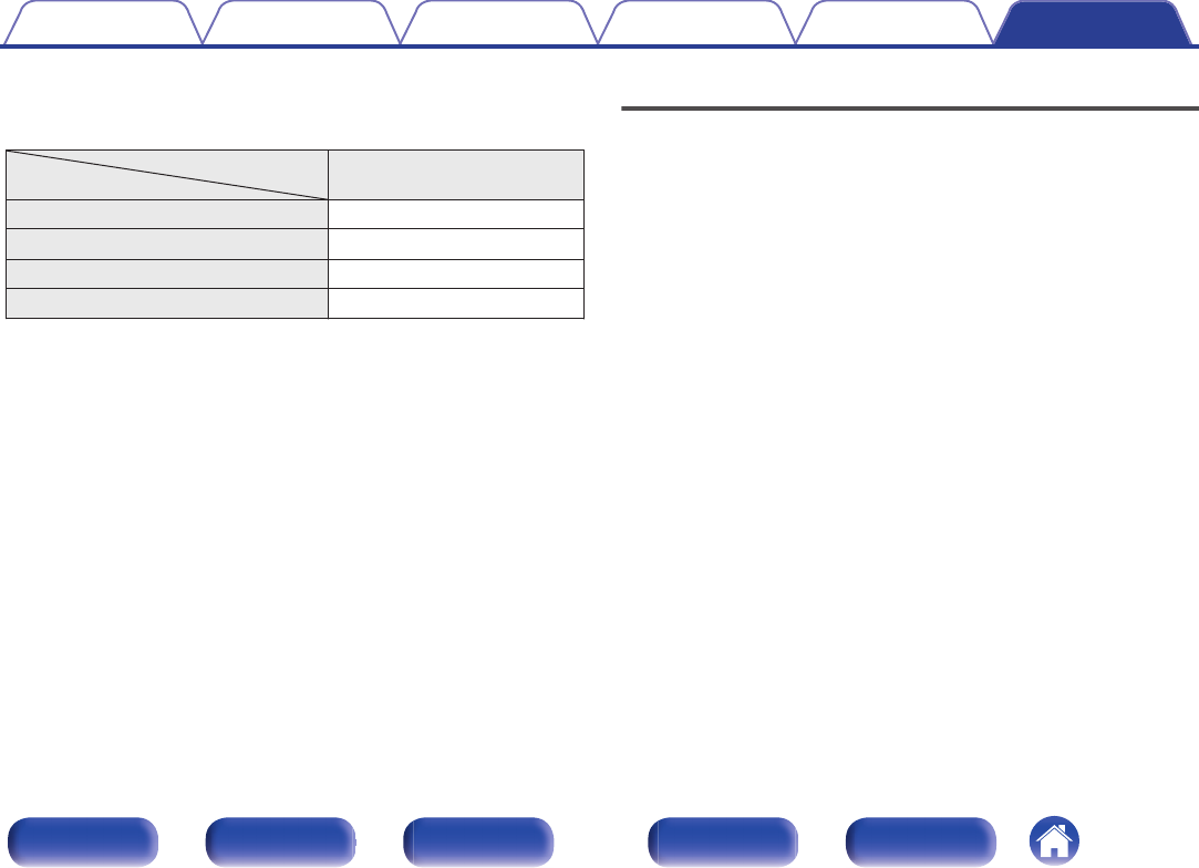
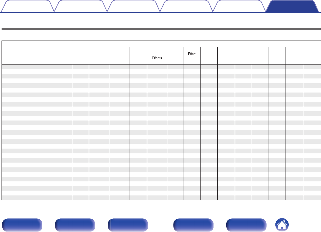
Channels output from the HEIGHT1 and HEIGHT2 speaker terminals can be changed to the following patterns according to the speaker systems being
used.
Set this from “Amp Assign” in the menu. (v p. 222)
Combination of height speakers to be usedConnected terminals
Number of height/
ceiling speakers
Number of Dolby
Speakers
Combination patternHEIGHT1 SPEAKERHEIGHT2 SPEAKER
2 speakersNone
Front HeightFront Height-
Top FrontTop Front-
Top MiddleTop Middle-
Top RearTop Rear-
Rear HeightRear Height-
None2 speakers
Front DolbyFront Dolby-
Surround DolbySurround Dolby-
Back DolbyBack Dolby-
4 speakersNone
Front Height & Top MiddleFront HeightTop Middle
Front Height & Top RearFront HeightTop Rear
Front Height & Rear Height
z
Front HeightRear Height
Front Height & Surr. HeightFront HeightSurr. Height
Top Front & Top RearTop FrontTop Rear
Top Front & Rear HeightTop FrontRear Height
Top Middle & Rear HeightTop MiddleRear Height
2 speakers2 speakers
Front Dolby & Top RearFront DolbyTop Rear
Front Dolby & Rear HeightFront DolbyRear Height
Front Height & Surr. DolbyFront HeightSurround Dolby
For the best Auro-3D experience Surround Height speakers are recommended, however you may substitute Rear Height speakers from a Dolby Atmos speaker setup in
place of Surround Height speakers.
Contents
ConnectionsPlaybackSettingsTipsAppendix
62
Front panelDisplayRear panelRemoteIndex
Connecting 13.1-channel speakers
This system, which is based on a 5.1-channel system, plays back up to 13.1-channels at the same time.
o
Example connection when using three sets of ceiling speakers
.
C
FLFR
SBL
SBR
SW
RSLS
TMLTMR
TRLTRR
TFLTFR
0
Set “Floor” - “Layout” to “5ch & SB” and “Height Sp” to “6ch” in the menu when
connecting in this configuration. (v p. 225)
.
1 CBL/SAT
PHONO
2
DVD
1
CBL/SAT
2
CD
1
TV
AUDIO
6 CD
2 DVD
12
3 Blu-ray
5 MEDIAPLAYER
4 GAME
RS-232C
7.1CH IN
REMOTE CONTROL
TRIGGER OUT
PRE OUT
COAXIALOPTICAL
STRAIGHT CABLE
I
R
DC12V 150mA MAX.
ZONE2ZONE3
FRONT
FRONT
SURROUND
CENTER
SUBWOOFER
SURROUND BACK
CENTER
SURROUND BACK
SURROUND
HEIGHT2
HEIGHT4/FRONT WIDE
1
AUDIO
(ASSIGNABLE)
AUDIO
DIGITAL AUDIO
(ASSIGNABLE)
2
SUBWOOFER
HEIGHT1
HEIGHT3
ASSIGNABLEASSIGNABLE
SPEAKERS
FRONTFRONT
CENTER
SURROUNDSURROUND
HEIGHT1HEIGHT1HEIGHT2HEIGHT2
ASSIGNABLE
HEIGHT4/FRONT WIDE
HEIGHT4/FRONT WIDE
ASSIGNABLE
HEIGHT3HEIGHT3
ASSIGNABLE
SURROUND BACKSURROUND BACK
TMRTML
TRRTRLTFRTFL
HEIGHT 1
z
HEIGHT 3
z
HEIGHT 2
z
SW
FRFLCSRSL
SBRSBL
z
You can change the combination of the HEIGHT1, HEIGHT2 and HEIGHT3
channels in the settings. (v p. 69)
Contents
ConnectionsPlaybackSettingsTipsAppendix
63
Front panelDisplayRear panelRemoteIndex
o
Example connection when using two sets of height speakers and one set of ceiling speakers
.
C
FLFR
SBL
SBR
SW
RSLS
TMLTMR
FHLFHR
RHLRHR
0
Set “Floor” - “Layout” to “5ch & SB” and “Height Sp” to “6ch” in the menu when
connecting in this configuration. (v p. 225)
.
1 CBL/SAT
PHONO
2
DVD
1
CBL/SAT
2
CD
1
TV
AUDIO
6 CD
2 DVD
12
3 Blu-ray
5 MEDIAPLAYER
4 GAME
RS-232C
7.1CH IN
REMOTE CONTROL
TRIGGER OUT
PRE OUT
COAXIALOPTICAL
STRAIGHT CABLE
I
R
DC12V 150mA MAX.
ZONE2ZONE3
FRONT
FRONT
SURROUND
CENTER
SUBWOOFER
SURROUND BACK
CENTER
SURROUND BACK
SURROUND
HEIGHT2
HEIGHT4/FRONT WIDE
1
AUDIO
(ASSIGNABLE)
AUDIO
DIGITAL AUDIO
(ASSIGNABLE)
2
SUBWOOFER
HEIGHT1
HEIGHT3
ASSIGNABLEASSIGNABLE
SPEAKERS
FRONTFRONT
CENTER
SURROUNDSURROUND
HEIGHT1HEIGHT1HEIGHT2HEIGHT2
ASSIGNABLE
HEIGHT4/FRONT WIDE
HEIGHT4/FRONT WIDE
ASSIGNABLE
HEIGHT3HEIGHT3
ASSIGNABLE
SURROUND BACKSURROUND BACK
TMRTML
HEIGHT 3
z
SW
FRFLCSRSL
SBRSBL
RHRRHLFHRFHL
HEIGHT 1
z
HEIGHT 2
z
z
You can change the combination of the HEIGHT1, HEIGHT2 and HEIGHT3
channels in the settings. (v p. 69)
Contents
ConnectionsPlaybackSettingsTipsAppendix
64
Front panelDisplayRear panelRemoteIndex
o
Example connection when using two sets of height speakers and one set of front wide speakers
.
C
FLFR
SW
RSLS
FHLFHR
RHLRHR
FWLFWR
SBL
SBR
0
Set “Floor” - “Layout” to “5ch & SB & FW” and “Height Sp” to “4ch” in the menu
when connecting in this configuration. (v p. 225)
.
1 CBL/SAT
PHONO
2
DVD
1
CBL/SAT
2
CD
1
TV
AUDIO
6 CD
2 DVD
12
3 Blu-ray
5 MEDIAPLAYER
4 GAME
RS-232C
7.1CH IN
REMOTE CONTROL
TRIGGER OUT
PRE OUT
COAXIALOPTICAL
STRAIGHT CABLE
I
R
DC12V 150mA MAX.
ZONE2ZONE3
FRONT
FRONT
SURROUND
CENTER
SUBWOOFER
SURROUND BACK
CENTER
SURROUND BACK
SURROUND
HEIGHT2
HEIGHT4/FRONT WIDE
1
AUDIO
(ASSIGNABLE)
AUDIO
DIGITAL AUDIO
(ASSIGNABLE)
2
ASSIGNABLE
SPEAKERS
SUBWOOFER
HEIGHT1
HEIGHT3
HEIGHT3HEIGHT3
FRONTFRONT
CENTER
SURROUNDSURROUND
ASSIGNABLE
HEIGHT4/FRONT WIDE
HEIGHT4/FRONT WIDE
ASSIGNABLEASSIGNABLE
HEIGHT1HEIGHT1HEIGHT2HEIGHT2
ASSIGNABLE
SURROUND BACKSURROUND BACK
FWRFWL
SW
FRFLCSRSL
RHRRHLFHRFHL
HEIGHT 1
z
HEIGHT 2
z
SBRSBL
z
You can change the combination of the HEIGHT1 and HEIGHT2 channels in the
settings. (v p. 69)
Contents
ConnectionsPlaybackSettingsTipsAppendix
65
Front panelDisplayRear panelRemoteIndex
o
Example connection when using three sets of Dolby Atmos Enabled speakers
.
C
SBL
SBR
SW
SRSL
FL
FR
FDLFDR
BDL
SDLSDR
BDR
0
Set “Floor” - “Layout” to “5ch & SB” and “Dolby Sp” to “6ch” in the menu when
connecting in this configuration. (v p. 225, 226)
.
1 CBL/SAT
PHONO
2
DVD
1
CBL/SAT
2
CD
1
TV
AUDIO
6 CD
2 DVD
12
3 Blu-ray
5 MEDIAPLAYER
4 GAME
RS-232C
7.1CH IN
REMOTE CONTROL
TRIGGER OUT
PRE OUT
COAXIALOPTICAL
STRAIGHT CABLE
I
R
DC12V 150mA MAX.
ZONE2ZONE3
FRONT
FRONT
SURROUND
CENTER
SUBWOOFER
SURROUND BACK
CENTER
SURROUND BACK
SURROUND
HEIGHT2
HEIGHT4/FRONT WIDE
1
AUDIO
(ASSIGNABLE)
AUDIO
DIGITAL AUDIO
(ASSIGNABLE)
2
SUBWOOFER
HEIGHT1
HEIGHT3
ASSIGNABLEASSIGNABLE
SPEAKERS
FRONTFRONT
CENTER
SURROUNDSURROUND
HEIGHT1HEIGHT1HEIGHT2HEIGHT2
ASSIGNABLE
HEIGHT4/FRONT WIDE
HEIGHT4/FRONT WIDE
ASSIGNABLE
HEIGHT3HEIGHT3
ASSIGNABLE
SURROUND BACKSURROUND BACK
SW
FRFLCSRSL
SBRSBL
BDRBDLFDRFDL
HEIGHT 1
z
SDRSDL
HEIGHT 3
z
HEIGHT 2
z
z
You can change the combination of the HEIGHT1, HEIGHT2 and HEIGHT3
channels in the settings. (v p. 69)
Contents
ConnectionsPlaybackSettingsTipsAppendix
66
Front panelDisplayRear panelRemoteIndex
o
Example connection for the Auro-3D 13.1-channel system
This speaker configuration is optimized for Auro-3D playback.
.
FLFR
SW
SRSL
C
FHLFHR
CH
SHLSHR
TS
SBRSBL
0
Set “Floor” - “Layout” to “5ch & SB” and “Height Sp” to “6ch” in the menu when
connecting in this configuration. (v p. 225)
Next, set “Height” - “Front Layout” to “Front Height & Center Height” and “Middle
Layout” to “Surr. Height & Top Surround”. (v p. 228)
.
1 CBL/SAT
PHONO
2
DVD
1
CBL/SAT
2
CD
1
TV
AUDIO
6 CD
2 DVD
12
3 Blu-ray
5 MEDIAPLAYER
4 GAME
RS-232C
7.1CH IN
REMOTE CONTROL
TRIGGER OUT
PRE OUT
COAXIALOPTICAL
STRAIGHT CABLE
IR
DC12V 150mA MAX.
ZONE2ZONE3
FRONT
FRONT
SURROUND
CENTER
SUBWOOFER
SURROUND BACK
CENTER
SURROUND BACK
SURROUND
HEIGHT2
HEIGHT4/FRONT WIDE
1
AUDIO
(ASSIGNABLE)
AUDIO
DIGITAL AUDIO
(ASSIGNABLE)
2
SUBWOOFER
HEIGHT1
HEIGHT3
ASSIGNABLEASSIGNABLE
SPEAKERS
FRONTFRONT
CENTER
SURROUNDSURROUND
HEIGHT1HEIGHT1HEIGHT2HEIGHT2
ASSIGNABLE
HEIGHT4/FRONT WIDE
HEIGHT4/FRONT WIDE
ASSIGNABLE
HEIGHT3HEIGHT3
ASSIGNABLE
SURROUND BACKSURROUND BACK
TSCH
SW
FRFLCSRSL
SBRSBL
SHRSHLFHRFHL
HEIGHT 1
z
1
HEIGHT 2
z
1
z
2
HEIGHT 3
z
1
z1
You can change the combination of the HEIGHT1, HEIGHT2 and HEIGHT3
channels in the settings. (v p. 69)
z2
For the best Auro-3D experience Surround Height speakers are
recommended, however you may substitute Rear Height speakers from a
Dolby Atmos speaker setup in place of Surround Height speakers.
Contents
ConnectionsPlaybackSettingsTipsAppendix
67
Front panelDisplayRear panelRemoteIndex
Connecting 15.1-channel speakers
This system can connect with up to 15.1-channel speakers and simultaneously play up to 13.1-channels for Dolby Atmos and Auro-3D playback.
Use the Front Height, Top Middle or Rear Height speakers for Dolby Atmos playback.
Use the Front Height, Rear Height, Center Height or Top Surround speakers for Auro-3D playback.
o
Example connection
.
TMLTMR
C
SW
RSLS
RHLRHR
SBL
SBR
FHLFHR
FLFR
CH
TS
0
Set “Floor” - “Layout” to “5ch & SB” and “Height Sp” to “8ch” in the menu when
connecting in this configuration. (v p. 225)
.
1 CBL/SAT
PHONO
2
DVD
1
CBL/SAT
2
CD
1
TV
AUDIO
6 CD
2 DVD
12
3 Blu-ray
5 MEDIAPLAYER
4 GAME
RS-232C
7.1CH IN
REMOTE CONTROL
TRIGGER OUT
PRE OUT
COAXIALOPTICAL
STRAIGHT CABLE
IR
DC12V 150mA MAX.
ZONE2ZONE3
FRONT
FRONT
SURROUND
CENTER
SUBWOOFER
SURROUND BACK
CENTER
SURROUND BACK
SURROUND
HEIGHT2
HEIGHT4/FRONT WIDE
1
AUDIO
(ASSIGNABLE)
AUDIO
DIGITAL AUDIO
(ASSIGNABLE)
2
SUBWOOFER
HEIGHT1
HEIGHT3
ASSIGNABLEASSIGNABLE
SPEAKERS
FRONTFRONT
CENTER
SURROUNDSURROUND
HEIGHT1HEIGHT1HEIGHT2HEIGHT2
ASSIGNABLE
SURROUND BACKSURROUND BACK
ASSIGNABLEASSIGNABLE
HEIGHT4/FRONT WIDE
HEIGHT3HEIGHT3
HEIGHT4/FRONT WIDE
HEIGHT 4
SW
FRFLCSRSL
SBRSBL
RHRRHLFHRFHL
HEIGHT 1HEIGHT 2
z
TMRTML
HEIGHT 3
TSCH
z
Use Surround Height speakers for optimal Auro-3D playback. Install Rear Height
speakers instead of Surround Height speakers to enjoy both Auro-3D and Dolby
Atmos with 13.1-channel playback.
Contents
ConnectionsPlaybackSettingsTipsAppendix
68
Front panelDisplayRear panelRemoteIndex
The combination of the HEIGHT1, HEIGHT2, HEIGHT3 and HEIGHT4 channels can be changed to the following patterns according to the speaker
system being used.
Set this from “Amp Assign” in the menu. (v p. 222)
Combinations of height speakers to be used
Connected speaker terminals
Number of
height / ceiling
speakers
Number of
Dolby
Speakers
Combination patternHEIGHT 1HEIGHT 2HEIGHT 3
HEIGHT 4/
FRONT
WIDEz1
2ch
2chNone
Front HeightFront Height---
Top FrontTop Front---
Top MiddleTop Middle---
Top RearTop Rear---
Rear HeightRear Height---
None2ch
Front DolbyFront Dolby---
Surround DolbySurround Dolby---
Back Dolbyz2
Back Dolby---
ContentsConnectionsPlaybackSettingsTipsAppendix
69
Front panelDisplayRear panelRemoteIndex
Combinations of height speakers to be used
Connected speaker terminals
Number of
height / ceiling
speakers
Number of
Dolby
Speakers
Combination patternHEIGHT 1HEIGHT 2HEIGHT 3
HEIGHT 4/
FRONT
WIDEz1
4ch
2ch2ch
Front Dolby & Top RearFront DolbyTop Rear--
Front Dolby & Rear HeightFront DolbyRear Height--
Front Height & Surr. DolbyFront HeightSurround Dolby--
Front Height & Back Dolbyz2
Front HeightBack Dolby--
Top Front & Surr. DolbyTop FrontSurround Dolby--
Top Front & Back Dolbyz2
Top FrontBack Dolby--
4chNone
Front Height & Top MiddleFront HeightTop Middle--
Front Height & Top RearFront HeightTop Rear--
Front Height & Rear Heightz3
Front HeightRear Height--
Front Height & Surr. HeightFront HeightSurr. Height--
Top Front & Top RearTop FrontTop Rear--
Top Front & Rear HeightTop FrontRear Height--
Top Middle & Rear HeightTop MiddleRear Height--
None4ch
Front Dolby & Surr. DolbyFront DolbySurround Dolby--
Front Dolby & Back Dolbyz2
Front DolbyBack Dolby--
ContentsConnectionsPlaybackSettingsTipsAppendix
70
Front panelDisplayRear panelRemoteIndex
Combinations of height speakers to be used
Connected speaker terminals
Number of
height / ceiling
speakers
Number of
Dolby
Speakers
Combination patternHEIGHT 1HEIGHT 2HEIGHT 3
HEIGHT 4/
FRONT
WIDEz1
5ch5chNone
Front Height & Rear Height & Top
Surroundz3
Front HeightRear HeightL: Top Surround-
Front Height & Surr. Height & Top
Surround
Front HeightSurr. HeightL: Top Surround-
Front Height & Rear Height &
Center Heightz3
Front HeightRear HeightR: Center Height-
Front Height & Surr. Height &
Center Height
Front HeightSurr. HeightR: Center Height-
ContentsConnectionsPlaybackSettingsTipsAppendix
71
Front panelDisplayRear panelRemoteIndex
Combinations of height speakers to be used
Connected speaker terminals
Number of
height / ceiling
speakers
Number of
Dolby
Speakers
Combination patternHEIGHT 1HEIGHT 2HEIGHT 3
HEIGHT 4/
FRONT
WIDEz1
6ch
6chNone
Front Height & Surr. Height &
Rear Heightz4
Front HeightRear HeightSurr. Height-
Front Height & Rear Height & Top
Surround & Center Heightz3
Front HeightRear Height
L: Top Surround
R: Center Height
-
Front Height & Surr. Height & Top
Surround & Center Height
Front HeightSurr. Height
L: Top Surround
R: Center Height
-
Front Height & Top Middle & Rear
Heightz3z5
Front HeightRear HeightTop Middle-
Top Front & Top Middle & Top
Rearz5
Top FrontTop RearTop Middle-
4ch2ch
Front Height & Surr. Dolby & Rear
Heightz3
Front HeightRear HeightSurround Dolby-
Top Front & Surr. Dolby & Top
Rear
Top FrontTop RearSurround Dolby-
2ch4ch
Front Height & Surr. Dolby & Back
Dolbyz2
Front DolbyBack DolbySurround Dolby-
Front Dolby & Top Middle & Back
Dolbyz2
Front DolbyBack DolbyTop Middle-
Front Dolby & Surr. Dolby & Rear
Height
Front DolbyRear HeightSurround Dolby-
None6ch
Front Dolby & Surr. Dolby & Back
Dolbyz2
Front DolbyBack DolbySurround Dolby-
ContentsConnectionsPlaybackSettingsTipsAppendix
72
Front panelDisplayRear panelRemoteIndex
Combinations of height speakers to be used
Connected speaker terminals
Number of
height / ceiling
speakers
Number of
Dolby
Speakers
Combination patternHEIGHT 1HEIGHT 2HEIGHT 3
HEIGHT 4/
FRONT
WIDEz1
7ch
7chNone
Front Height & Top Middle & Rear
Height & Top Surroundz3
Front HeightRear HeightTop MiddleL: Top Surround
Front Height & Top Middle & Rear
Height & Center Heightz3
Front HeightRear HeightTop MiddleR: Center Height
5ch2ch
Front Height & Surr. Dolby & Rear
Height & Top Surroundz3
Front HeightRear HeightSurround DolbyL: Top Surround
Front Height & Surr. Dolby & Rear
Height & Center Heightz3
Front HeightRear HeightSurround DolbyR: Center Height
8ch
8chNone
Front Height & Top Middle & Rear
Height & Top Surround & Center
Heightz3
Front HeightRear HeightTop Middle
L: Top Surround
R: Center Height
6ch2ch
Front Height & Surr. Dolby & Rear
Height & Top Surround & Center
Heightz3
Front HeightRear HeightSurround Dolby
L: Top Surround
R: Center Height
z1Connect to the HEIGHT4/FRONT WIDE speaker terminal to use Front Wide speakers. Set “Floor” - “Layout” in the menu to “5ch & FW” or “5ch & SB & FW”. (v p. 225)
z2
This combination can be selected when using Surround Back speakers.
z3
For the best Auro-3D experience Surround Height speakers are recommended, however you may substitute Rear Height speakers from a Dolby Atmos speaker setup in
place of Surround Height speakers.
z4
Use 2 sets of Height speakers in the appropriate sound modes for Dolby Atmos, DTS:X or Auro-3D playback.
Use the Front Height and Rear Height speakers for Dolby Atmos or DTS:X playback.
Use the Front Height and Surround Height speakers for Auro-3D playback.
z5This combination can be selected when “Floor” - “Layout” in the menu to “5ch” or “5ch & SB”. (v p. 225)
Contents
ConnectionsPlaybackSettingsTipsAppendix
73
Front panelDisplayRear panelRemoteIndex
Bi-amp connection
o
11.1-channel playback (bi-amp connection of front speakers)
This system plays back 11.1-channels. You can use the bi-amp connection for front speakers. Bi-amp connection is a method to connect separate
amplifiers to the tweeter terminal and woofer terminal of a speaker that supports bi-amplification. This connection enables back EMF (power returned
without being output) from the woofer to flow into the tweeter without affecting the sound quality, producing a higher sound quality.
.
C
SW
RSLS
FHLFHR
RHLRHR
SBL
SBR
FL
(Bi-Amp)(Bi-Amp)
FR
NOTE
0
When making bi-amp connections, be sure to remove the short-circuiting plate or
wire between the speaker’s woofer and tweeter terminals.
.
1 CBL/SAT
PHONO
2
DVD
1
CBL/SAT
2
CD
1
TV
AUDIO
6 CD
2 DVD
12
3 Blu-ray
5 MEDIAPLAYER
4 GAME
RS-232C
7.1CH IN
REMOTE CONTROL
TRIGGER OUT
PRE OUT
COAXIALOPTICAL
STRAIGHT CABLE
IR
DC12V 150mA MAX.
ZONE2ZONE3
FRONT
FRONT
SURROUND
CENTER
SUBWOOFER
SURROUND BACK
CENTER
SURROUND BACK
SURROUND
HEIGHT2
HEIGHT4/FRONT WIDE
1
AUDIO
(ASSIGNABLE)
AUDIO
DIGITAL AUDIO
(ASSIGNABLE)
2
SUBWOOFER
HEIGHT1
HEIGHT3
ASSIGNABLEASSIGNABLE
SPEAKERS
FRONTFRONT
CENTER
SURROUNDSURROUND
HEIGHT1HEIGHT1HEIGHT2HEIGHT2
ASSIGNABLE
SURROUND BACKSURROUND BACK
ASSIGNABLE
HEIGHT4/FRONT WIDE
HEIGHT4/FRONT WIDE
ASSIGNABLE
HEIGHT3HEIGHT3
wq
(R)
wq
(L)
SW
CSRSL
SBRSBL
FHRFHL
zz
RHRRHL
zz
FRFL
z
The height speakers, ceiling speakers and Dolby Atmos Enabled speakers can
be connected to the HEIGHT1 and HEIGHT2 speaker terminals. Set the speaker
to be connected from “Height” in the menu. (v p. 225)
Contents
ConnectionsPlaybackSettingsTipsAppendix
74
Front panelDisplayRear panelRemoteIndex
o
5.1-channel playback : Bi-amp connection of front, center and surround speakers
This system plays back 5.1-channels.
You can use the bi-amp connection for all front, center and surround speakers.
.
SW
FLFR
SLSR
C
(Bi-Amp)
(Bi-Amp)
(Bi-Amp)
(Bi-Amp)
(Bi-Amp)
.
1 CBL/SAT
PHONO
2
DVD
1
CBL/SAT
2
CD
1
TV
AUDIO
6 CD
2 DVD
12
3 Blu-ray
5 MEDIAPLAYER
4 GAME
RS-232C
7.1CH IN
REMOTE CONTROL
TRIGGER OUT
PRE OUT
COAXIALOPTICAL
STRAIGHT CABLE
I
R
DC12V 150mA MAX.
ZONE2ZONE3
FRONT
FRONT
SURROUND
CENTER
SUBWOOFER
SURROUND BACK
CENTER
SURROUND BACK
SURROUND
HEIGHT2
HEIGHT4/FRONT WIDE
1
AUDIO
(ASSIGNABLE)
AUDIO
DIGITAL AUDIO
(ASSIGNABLE)
2
SUBWOOFER
HEIGHT1
HEIGHT3
ASSIGNABLEASSIGNABLEASSIGNABLE
SPEAKERS
FRONTFRONT
CENTER
SURROUNDSURROUND
SURROUND BACKSURROUND BACK
HEIGHT1HEIGHT2HEIGHT2
ASSIGNABLEASSIGNABLE
HEIGHT4/FRONT WIDE
HEIGHT3HEIGHT3
HEIGHT1
HEIGHT4/FRONT WIDE
wqwq
(L)
wq
(R)
wq
(R)
wq
(L)
SW
CFLFR
SRSL
Contents
ConnectionsPlaybackSettingsTipsAppendix
75
Front panelDisplayRear panelRemoteIndex
Connecting 11.1-channel speakers: Second pair of front speakers
This system enables switching playback between front speakers A and B as desired.
.
C
SW
RSLS
FHLFHR
RHLRHR
SBL
SBR
FL
(A)
FL
(B)
FR
(B)
FR
(A)
.
1 CBL/SAT
PHONO
2
DVD
1
CBL/SAT
2
CD
1
TV
AUDIO
6 CD
2 DVD
12
3 Blu-ray
5 MEDIAPLAYER
4 GAME
RS-232C
7.1CH IN
REMOTE CONTROL
TRIGGER OUT
PRE OUT
COAXIALOPTICAL
STRAIGHT CABLE
IR
DC12V 150mA MAX.
ZONE2ZONE3
FRONT
FRONT
SURROUND
CENTER
SUBWOOFER
SURROUND BACK
CENTER
SURROUND BACK
SURROUND
HEIGHT2
HEIGHT4/FRONT WIDE
1
AUDIO
(ASSIGNABLE)
AUDIO
DIGITAL AUDIO
(ASSIGNABLE)
2
SUBWOOFER
HEIGHT1
HEIGHT3
ASSIGNABLEAS SIGNABLE
SPEAKERS
FRONTFRONT
CENTER
SURROUNDSURROUND
HEIGHT1HEIGHT1HEIGHT2HEIGHT2
ASSIGNABLE
SURROUND BACKSURROUND BACK
ASSIGNABLE
HEIGHT4/FRONT WIDE
HEIGHT4/FRONT WIDE
ASSIGNABLE
HEIGHT3HEIGHT3
SW
CSRSL
SBRSBL
FR
(B)
FHRFHL
zz
RHRRHL
zz
FL
(B)
FR
(A)
FL
(A)
z
The height speakers, ceiling speakers and Dolby Atmos Enabled speakers can
be connected to the HEIGHT1 and HEIGHT2 speaker terminals. Set the speaker
to be connected from “Height” in the menu. (v p. 225)
Contents
ConnectionsPlaybackSettingsTipsAppendix
76
Front panelDisplayRear panelRemoteIndex
Connecting multi-zone speakers
o
11.1-channel playback (MAIN ZONE) + 2-channel playback (ZONE2 or ZONE3)
This type of configuration plays back 11.1-channels in MAIN ZONE and 2-channels in ZONE2.
(Speakers can output audio from ZONE3 instead of ZONE2 (Assign Mode: 11.1ch + ZONE3)).
.
MAIN ZONE
ZONE2
ZONE2
L
ZONE2
R
C
SW
RSLS
FHLFHR
RHLRHR
SBL
SBR
FLFR
.
1 CBL/SAT
PHONO
2
DVD
1
CBL/SAT
2
CD
1
TV
AUDIO
6 CD
2 DVD
12
3 Blu-ray
5 MEDIAPLAYER
4 GAME
RS-232C
7.1CH IN
REMOTE CONTROL
TRIGGER OUT
PRE OUT
COAXIALOPTICAL
STRAIGHT CABLE
IR
DC12V 150mA MAX.
ZONE2ZONE3
FRONT
FRONT
SURROUND
CENTER
SUBWOOFER
SURROUND BACK
CENTER
SURROUND BACK
SURROUND
HEIGHT2
HEIGHT4/FRONT WIDE
1
AUDIO
(ASSIGNABLE)
AUDIO
DIGITAL AUDIO
(ASSIGNABLE)
2
SUBWOOFER
HEIGHT1
HEIGHT3
ASSIGNABLEAS SIGNABLE
SPEAKERS
FRONTFRONT
CENTER
SURROUNDSURROUND
HEIGHT1HEIGHT1HEIGHT2HEIGHT2
ASSIGNABLE
SURROUND BACKSURROUND BACK
ASSIGNABLE
HEIGHT4/FRONT WIDE
HEIGHT4/FRONT WIDE
ASSIGNABLE
HEIGHT3HEIGHT3
SW
CSRFRFLSL
SBRSBL
FHRFHL
zz
RHRRHL
zz
ZONE2
R
ZONE2
L
z
The height speakers, ceiling speakers and Dolby Atmos Enabled speakers can
be connected to the HEIGHT1 and HEIGHT2 speaker terminals. Set the speaker
to be connected from “Height” in the menu. (v p. 225)
Contents
ConnectionsPlaybackSettingsTipsAppendix
77
Front panelDisplayRear panelRemoteIndex
o
9.1-channel playback (bi-amp connection of front speakers: MAIN ZONE) + 2-channel playback
(ZONE2)
This type of configuration plays back 9.1-channels in MAIN ZONE and 2-channels in ZONE2. You can use the bi-amp connection for front speakers in
MAIN ZONE.
.
MAIN ZONE
ZONE2
ZONE2
L
ZONE2
R
C
SW
RSLS
SBL
SBR
FL
(Bi-Amp)(Bi-Amp)
FR
FHL
FHR
.
1 CBL/SAT
PHONO
2
DVD
1
CBL/SAT
2
CD
1
TV
AUDIO
6 CD
2 DVD
12
3 Blu-ray
5 MEDIAPLAYER
4 GAME
RS-232C
7.1CH IN
REMOTE CONTROL
TRIGGER OUT
PRE OUT
COAXIALOPTICAL
STRAIGHT CABLE
I
R
DC12V 150mA MAX.
ZONE2ZONE3
FRONT
FRONT
SURROUND
CENTER
SUBWOOFER
SURROUND BACK
CENTER
SURROUND BACK
SURROUND
HEIGHT2
HEIGHT4/FRONT WIDE
1
AUDIO
(ASSIGNABLE)
AUDIO
DIGITAL AUDIO
(ASSIGNABLE)
2
SUBWOOFER
HEIGHT1
HEIGHT3
ASSIGNABLEAS SIGNABLE
SPEAKERS
FRONTFRONT
CENTER
SURROUNDSURROUND
HEIGHT1HEIGHT1HEIGHT2HEIGHT2
ASSIGNABLE
SURROUND BACKSURROUND BACK
ASSIGNABLE
HEIGHT4/FRONT WIDE
HEIGHT4/FRONT WIDE
ASSIGNABLE
HEIGHT3HEIGHT3
wq
(R)
wq
(L)
SW
CSRSL
SBRSBL
FHRFHL
zz
FRFL
ZONE2
R
ZONE2
L
z
The height speakers, ceiling speakers and Dolby Atmos Enabled speakers can
be connected to the HEIGHT1 and HEIGHT2 speaker terminals. Set the speaker
to be connected from “Height” in the menu. (v p. 225)
Use an HDMI cable to connect a TV that is compatible with the ARC / eARC function to this unit.
Set “HDMI Control” to “On” or “ARC” to “On” when using a TV that supports the ARC function. (v p. 195)
Using an eARC function-compatible television enables audio playback from the speaker connected to this unit, regardless of “HDMI Control” and “ARC”
settings in the menu.
.
1 CBL/SAT
PHONO
2 DVD
2
DVD
1
CBL/SAT
3 Blu-ray6 AUX27 C D
2
CD
1
TV
AUDIO
6 CD
4 GAME
5 MEDIA PLAYER
2 DVD
12
3 Blu-ray
5 MEDIAPLAYER
4 GAME
1
CBL/SAT
1
CBL/SAT
2 DVD
2 DVD3
Blu-ray
4 GAME
RS-232C
7.1CH IN
REMOTE CONTROL
TRIGGER OUT
PRE OUT
(ASSIGNABLE)
VIDEO
VIDEO
(ASSIGNABLE)(ASSIGNABLE)
COMPONENT VIDEO
COMPONENT VIDEO
MONITOR
MONITOR/ZONE3
ZONE2
3 Blu-ray
COAXIALOPTICAL
STRAIGHT CABLE
I
R
DC12V 150mA MAX.
ZONE2ZONE3
FRONT
FRONT
SURROUND
CENTER
SUBWOOFER
SURROUND BACK
CENTER
SURROUND BACK
SURROUND
HEIGHT2
HEIGHT4/FRONT WIDE
1
AUDIO
(ASSIGNABLE)
AUDIO
DIGITAL AUDIO
(ASSIGNABLE)
2
ASSIGNABLEASSIGNABLE
ASSIGNABLEASSIGNABLE
ASSIGNABLE
1 CBL/SAT
Bluetooth
/
Wi-Fi
ANTENNA
Bluetooth
/
Wi-Fi
ANTENNA
AC IN
NETWORK
Y
P
B/
C
B
PR/
C
R
Denon Link HD
SPEAKERS
SUBWOOFER
HEIGHT1
HEIGHT3
POWER SUPPLY
5V/1.5A
FRONT
HEIGHT4/FRONT WIDE
HEIGHT3HEIGHT3
FRONT
CENTER
SURROUNDSURROUND
SURROUND BACKSURROUND BACK
HEIGHT1HEIGHT1HEIGHT2HEIGHT2
HEIGHT4/FRONT WIDE
ARC
MONITOR1
ZONE2
MONITOR2
SIGNAL
GND
TUNER
AUDIO
(ARC)
IN
HDMI
TV
Contents
ConnectionsPlaybackSettingsTipsAppendix
83
Front panelDisplayRear panelRemoteIndex
0
When using the ARC / eARC function, connect to the HDMI MONITOR 1 connector.
0
eARC function settings may be required depending on the eARC function-compatible television you are using. Make sure eARC is set to on if this setting exists on your
television. For more information, check your television’s owner’s manual.
0
When an ARC and an eARC function-compatible televisions are connected, the eARC function-compatible television is prioritized.
0
Use a “High Speed HDMI Cable with Ethernet” when using an ARC / eARC function-compatible television.
ContentsConnectionsPlaybackSettingsTipsAppendix
84
Front panelDisplayRear panelRemoteIndex
Connection 2 : TV equipped with an HDMI connector and incompatible with the ARC
To listen to audio from TV on this unit, use an optical cable to connect the TV to this unit.
.
1 CBL/SAT
PHONO
2 DVD
3 Blu-ray6 AUX27 C D
6 CD
4 GAME
5 MEDIA PLAYER
2 DVD
12
3 Blu-ray
5 MEDIAPLAYER
4 GAME
1
CBL/SAT
1
CBL/SAT
2 DVD
2 DVD3
Blu-ray
4 GAME
RS-232C
7.1CH IN
REMOTE CONTROL
TRIGGER OUT
PRE OUT
(ASSIGNABLE)
VIDEO
VIDEO
(ASSIGNABLE)(ASSIGNABLE)
COMPONENT VIDEO
COMPONENT VIDEO
MONITOR
MONITOR/ZONE3
ZONE2
3 Blu-ray
STRAIGHT CABLE
I
R
DC12V 150mA MAX.
ZONE2ZONE3
FRONT
FRONT
SURROUND
CENTER
SUBWOOFER
SURROUND BACK
CENTER
SURROUND BACK
SURROUND
HEIGHT2
HEIGHT4/FRONT WIDE
1
AUDIO
(ASSIGNABLE)
AUDIO
2
ASSIGNABLEASSIGNABLE
ASSIGNABLEASSIGNABLE
ASSIGNABLE
1 CBL/SAT
Bluetooth
/
Wi-Fi
ANTENNA
Bluetooth
/
Wi-Fi
ANTENNA
AC IN
NETWORK
Y
P
B/
C
B
PR/
C
R
Denon Link HD
SPEAKERS
SUBWOOFER
HEIGHT1
HEIGHT3
POWER SUPPLY
5V/1.5A
FRONT
HEIGHT4/FRONT WIDE
HEIGHT3HEIGHT3
FRONT
CENTER
SURROUNDSURROUND
SURROUND BACKSURROUND BACK
HEIGHT1HEIGHT1HEIGHT2HEIGHT2
HEIGHT4/FRONT WIDE
ARC
MONITOR1
ZONE2
MONITOR2
2
DVD
1
CBL/SAT
2
CD
1
TV
AUDIO
COAXIALOPTICAL
DIGITAL AUDIO
(ASSIGNABLE)
SIGNAL
GND
TUNER
AUDIO
OUT
OPTICAL
OUTIN
IN
HDMI
TV
Contents
ConnectionsPlaybackSettingsTipsAppendix
85
Front panelDisplayRear panelRemoteIndex
Connection 3 : TV equipped without an HDMI connector
Use a component video or a video cable to connect the TV to this unit.
To listen to audio from TV on this unit, use an optical cable to connect the TV to this unit.
.
1 CBL/SAT
PHONO
2 DVD
3 Blu-ray6 AUX27 C D
6 CD
4 GAME
5 MEDIA PLAYER
2 DVD
12
3 Blu-ray
5 MEDIAPLAYER
4 GAME
1
CBL/SAT
1
CBL/SAT
2 DVD
2 DVD3
Blu-ray
4 GAME
RS-232C
7.1CH IN
REMOTE CONTROL
TRIGGER OUT
PRE OUT
(ASSIGNABLE)
VIDEO
(ASSIGNABLE)
COMPONENT VIDEO
ARC
MONITOR1
ZONE2
3 Blu-ray
MONITOR2
STRAIGHT CABLE
I
R
DC12V 150mA MAX.
ZONE2ZONE3
FRONT
FRONT
SURROUND
CENTER
SUBWOOFER
SURROUND BACK
CENTER
SURROUND BACK
SURROUND
HEIGHT2
HEIGHT4/FRONT WIDE
1
AUDIO
(ASSIGNABLE)
AUDIO
2
ASSIGNABLEASSIGNABLE
ASSIGNABLEASSIGNABLE
ASSIGNABLE
1 CBL/SAT
Bluetooth
/
Wi-Fi
ANTENNA
Bluetooth
/
Wi-Fi
ANTENNA
AC IN
NETWORK
Denon Link HD
SPEAKERS
SUBWOOFER
HEIGHT1
HEIGHT3
POWER SUPPLY
5V/1.5A
FRONT
HEIGHT4/FRONT WIDE
HEIGHT3HEIGHT3
FRONTCENTERSURROUNDSURROUND
SURROUND BACKSURROUND BACK
HEIGHT1HEIGHT1HEIGHT2HEIGHT2
HEIGHT4/FRONT WIDE
(ASSIGNABLE)
COMPONENT VIDEO
MONITOR
Y
P
B/
C
B
PR/
C
R
VIDEO
MONITOR/ZONE3
ZONE2
2
DVD
1
CBL/SAT
2
CD
1
TV
AUDIO
PRE OUT
COAXIALOPTICAL
DIGITAL AUDIO
(ASSIGNABLE)
SIGNAL
GND
TUNER
AUDIO
OUT
OPTICAL
OUT
IN
VIDEO
COMPONENT VIDEO
YP
BPR
IN
IN
TV
or
Contents
ConnectionsPlaybackSettingsTipsAppendix
86
Front panelDisplayRear panelRemoteIndex
Connecting a playback device
This unit is equipped with three types of video input connectors (HDMI, component video and composite video) and three types of audio input connectors
(HDMI, digital audio and audio).
Select input connectors on this unit according to the connectors equipped on the device you want to connect.
If the device connected to this unit is equipped with an HDMI connector, it is recommended to use HDMI connections.
In the HDMI connection, audio and video signals can be transmitted through a single HDMI cable.
0
“Connecting a set-top box (Satellite tuner/cable TV)” (v p. 88)
0
“Connecting a DVD player or Blu-ray Disc player” (v p. 89)
0
“Connecting a Blu-ray Disc player compatible with the Denon Link HD function” (v p. 90)
0
“Connecting a video camcorder or game console” (v p. 91)
0
“Connecting a turntable” (v p. 92)
0
“Connecting a device with a multi-channel output connector” (v p. 93)
0
Connect devices to this unit as indicated by the input sources printed on the audio/video input connectors of this unit.
0
The source that is assigned to the HDMI IN, DIGITAL AUDIO IN, COMPONENT VIDEO IN, VIDEO IN and AUDIO IN connectors can be changed. See “Input Assign” on how
to change the input source assigned to the input connectors. (v p. 206)
0
To play back audio signals that are input to this unit on a TV connected via HDMI, set in the menu “HDMI Audio Out” to “TV”. (v p. 193)
0
To enjoy content that is copyright protected by HDCP 2.2, use a playback device and TV compatible with HDCP 2.2 only.
ContentsConnectionsPlaybackSettingsTipsAppendix
87
Front panelDisplayRear panelRemoteIndex
Connecting a set-top box (Satellite tuner/cable TV)
This explanation uses the connection with a satellite tuner/cable TV STB as an example.
Select the input connectors on this unit to match the connectors on the device that you want to connect to.
.
PHONO
12
RS-232C
7.1CH IN
REMOTE CONTROL
TRIGGER OUT
PRE OUT
VIDEO
(ASSIGNABLE)
COMPONENT VIDEO
ARC
MONITOR1
MONITOR
MONITOR/ZONE3
ZONE2
ZONE2
MONITOR2
STRAIGHT CABLE
I
R
DC12V 150mA MAX.
ZONE2ZONE3
FRONT
FRONT
SURROUND
CENTER
SUBWOOFER
SURROUND BACK
CENTER
SURROUND BACK
SURROUND
HEIGHT2
HEIGHT4/FRONT WIDE
1
AUDIO
2
ASSIGNABLEASSIGNABLE
ASSIGNABLEASSIGNABLE
ASSIGNABLE
Bluetooth
/
Wi-Fi
ANTENNA
Bluetooth
/
Wi-Fi
ANTENNA
AC IN
NETWORK
Y
P
B/
C
B
PR/
C
R
Denon Link HD
SPEAKERS
SUBWOOFER
HEIGHT1
HEIGHT3
POWER SUPPLY
5V/1.5A
FRONT
HEIGHT4/FRONT WIDE
HEIGHT3HEIGHT3
FRONT
CENTER
SURROUNDSURROUND
SURROUND BACKSURROUND BACK
HEIGHT1HEIGHT1HEIGHT2HEIGHT2
HEIGHT4/FRONT WIDE
2
DVD
1
CBL/SAT
2
CD
1
TV
AUDIO
COAXIALOPTICAL
DIGITAL AUDIO
(ASSIGNABLE)
1 CBL/SAT
6 CD
2 DVD
3 Blu-ray
5 MEDIAPLAYER
4 GAME
AUDIO
(ASSIGNABLE)
2 DVD
3 Blu-ray6 AUX27 C D4 GAME
5 MEDIA PLAYER
1 CBL/SAT
1
CBL/SAT
2 DVD
4 GAME
(ASSIGNABLE)
VIDEO
3 Blu-ray
1
CBL/SAT
2 DVD3
Blu-ray
(ASSIGNABLE)
COMPONENT VIDEO
SIGNAL
GND
TUNER
AUDIO
R
L
R
L
OUT
HDMI
OUT
COAXIAL
AUDIO
AUDIO
RL
OUT
OUT
VIDEO
VIDEO
COMPONENT VIDEO
YP
BPR
OUT
oror
Satellite tuner/
Cable TV
Satellite tuner/
Cable TV
(HDMI incompatible device)
Contents
ConnectionsPlaybackSettingsTipsAppendix
88
Front panelDisplayRear panelRemoteIndex
Connecting a DVD player or Blu-ray Disc player
This explanation uses the connection with a DVD player or Blu-ray Disc player as an example.
Select the input connectors on this unit to match the connectors on the device that you want to connect to.
0
When connecting a Blu-ray Disc player that is compatible with Denon Link
HD, see “Connecting a Blu-ray Disc player compatible with the Denon
Link HD function” (v p. 90).
PHONO
12
RS-232C
7.1CH IN
REMOTE CONTROL
TRIGGER OUT
PRE OUT
VIDEO
(ASSIGNABLE)
COMPONENT VIDEO
ARC
MONITOR1
MONITOR
MONITOR/ZONE3
ZONE2
ZONE2
MONITOR2
STRAIGHT CABLE
I
R
DC12V 150mA MAX.
ZONE2ZONE3
FRONT
FRONT
SURROUND
CENTER
SUBWOOFER
SURROUND BACK
CENTER
SURROUND BACK
SURROUND
HEIGHT2
HEIGHT4/FRONT WIDE
1
AUDIO
2
ASSIGNABLEASSIGNABLE
ASSIGNABLEASSIGNABLE
ASSIGNABLE
Bluetooth
/
Wi-Fi
ANTENNA
Bluetooth
/
Wi-Fi
ANTENNA
AC IN
NETWORK
Y
P
B/
C
B
PR/
C
R
Denon Link HD
SPEAKERS
SUBWOOFER
HEIGHT1
HEIGHT3
POWER SUPPLY
5V/1.5A
FRONT
HEIGHT4/FRONT WIDE
HEIGHT3HEIGHT3
FRONT
CENTER
SURROUNDSURROUND
SURROUND BACKSURROUND BACK
HEIGHT1HEIGHT1HEIGHT2HEIGHT2
HEIGHT4/FRONT WIDE
2
DVD
1
CBL/SAT
2
CD
1
TV
AUDIO
COAXIALOPTICAL
DIGITAL AUDIO
(ASSIGNABLE)
1 CBL/SAT
6 CD
2 DVD
3 Blu-ray
5 MEDIAPLAYER
4 GAME
AUDIO
(ASSIGNABLE)
2 DVD
3 Blu-ray6 AUX27 C D4 GAME
5 MEDIA PLAYER
1 CBL/SAT
1
CBL/SAT
2 DVD
4 GAME
(ASSIGNABLE)
VIDEO
3 Blu-ray
1
CBL/SAT
2 DVD3
Blu-ray
(ASSIGNABLE)
COMPONENT VIDEO
SIGNAL
GND
TUNER
AUDIO
R
L
R
L
OUT
HDMI
OUT
COAXIAL
AUDIO
AUDIO
RL
OUT
OUT
VIDEO
VIDEO
COMPONENT VIDEO
YP
BPR
OUT
OUT
HDMI
(HDMI incompatible device)
DVD player
DVD player
Blu-ray Disc
player
oror
Contents
ConnectionsPlaybackSettingsTipsAppendix
89
Front panelDisplayRear panelRemoteIndex
Connecting a Blu-ray Disc player compatible with the Denon Link HD function
By making a Denon Link HD connection to a player compatible with the Denon Link HD function, you can enjoy higher quality playback compared with
when only the HDMI connector connection is made.
0
Both HDMI and Denon Link HD connections are required for this
connection method.
0
Set “Input Mode” on the menu to “Auto” or “HDMI”. (v p. 210)
1 CBL/SAT
PHONO
2
DVD
1
CBL/SAT
2
CD
1
TV
AUDIO
6 CD
2 DVD
12
3 Blu-ray
5 MEDIAPLAYER
4 GAME
1
CBL/SAT
1
CBL/SAT
2 DVD
2 DVD3
Blu-ray
4 GAME
RS-232C
7.1CH IN
REMOTE CONTROL
TRIGGER OUT
PRE OUT
(ASSIGNABLE)
VIDEO
VIDEO
(ASSIGNABLE)(ASSIGNABLE)
COMPONENT VIDEO
COMPONENT VIDEO
ARC
MONITOR1
MONITOR
MONITOR/ZONE3
ZONE2
ZONE2
3 Blu-ray
MONITOR2
COAXIALOPTICAL
STRAIGHT CABLE
I
R
DC12V 150mA MAX.
ZONE2ZONE3
FRONT
FRONT
SURROUND
CENTER
SUBWOOFER
SURROUND BACK
CENTER
SURROUND BACK
SURROUND
HEIGHT2
HEIGHT4/FRONT WIDE
1
AUDIO
(ASSIGNABLE)
AUDIO
DIGITAL AUDIO
(ASSIGNABLE)
2
ASSIGNABLEASSIGNABLE
ASSIGNABLEASSIGNABLE
ASSIGNABLE
Bluetooth
/
Wi-Fi
ANTENNA
Bluetooth
/
Wi-Fi
ANTENNA
AC IN
NETWORK
Y
P
B/
C
B
PR/
C
R
SPEAKERS
SUBWOOFER
HEIGHT1
HEIGHT3
POWER SUPPLY
5V/1.5A
FRONT
HEIGHT4/FRONT WIDE
HEIGHT3HEIGHT3
FRONT
CENTER
SURROUNDSURROUND
SURROUND BACKSURROUND BACK
HEIGHT1HEIGHT1HEIGHT2HEIGHT2
HEIGHT4/FRONT WIDE
Denon Link HD
2 DVD
3 Blu-ray6 AUX27 C D4 GAME
5 MEDIA PLAYER
1 CBL/SAT
SIGNAL
GND
TUNER
AUDIO
Link HD
Denon
OUT
HDMI
Blu-ray Disc
player
Contents
ConnectionsPlaybackSettingsTipsAppendix
90
Front panelDisplayRear panelRemoteIndex
Connecting a video camcorder or game console
This explanation uses the connection with a video camcorders as an example.
Connect a playback device to this unit, such as a video camcorder or game console.
.
OUT
HDMI
Video
camcorder
Contents
ConnectionsPlaybackSettingsTipsAppendix
91
Front panelDisplayRear panelRemoteIndex
Connecting a turntable
This unit is compatible with turntables equipped with a moving magnet (MM) phono cartridge. When you connect to a turntable with a low output moving
coil (MC) cartridge, use a commercially available MC head amp or a step-up transformer.
If you set this unit’s input source to “Phono” and you accidentally increase the volume without having a turntable connected, you may hear a hum noise
from the speakers.
NOTE
0
The earth terminal (SIGNAL GND) of this unit is not for safety grounding
purposes. If this terminal is connected when there is a lot of noise, the noise can
be reduced. Note that depending on the turntable, connecting the ground line
may have the reverse effect of increasing noise. In this case, it is not necessary to
connect the ground line.
1 CBL/SAT
2 DVD
2
DVD
1
CBL/SAT
3 Blu-ray6 AU X27 CD
2
CD
1
TV
AUDIO
6 CD
4 GAME
5 MEDIA PLAYER
2 DVD
12
3 Blu-ray
5 MEDIAPLAYER
4 GAME
1
CBL/SAT
1
CBL/SAT
2 DVD
2 DVD3
Blu-ray
4 GAME
RS-232C
7.1CH IN
REMOTE CONTROL
TRIGGER OUT
PRE OUT
(ASSIGNABLE)
VIDEO
VIDEO
(ASSIGNABLE)(ASSIGNABLE)
COMPONENT VIDEO
COMPONENT VIDEO
ARC
MONITOR1
MONITOR
MONITOR/ZONE3
ZONE2
ZONE2
3 Blu-ray
MONITOR2
COAXIALOPTICAL
STRAIGHT CABLE
I
R
DC12V 150mA MAX.
ZONE2ZONE3
FRONT
FRONT
SURROUND
CENTER
SUBWOOFER
SURROUND BACK
CENTER
SURROUND BACK
SURROUND
HEIGHT2
HEIGHT4/FRONT WIDE
1
AUDIO
(ASSIGNABLE)
DIGITAL AUDIO
(ASSIGNABLE)
2
ASSIGNABLEASSIGNABLE
ASSIGNABLEASSIGNABLE
ASSIGNABLE
1 CBL/SAT
Bluetooth
/
Wi-Fi
ANTENNA
Bluetooth
/
Wi-Fi
ANTENNA
AC IN
NETWORK
Y
P
B/
C
B
PR/
C
R
Denon Link HD
SPEAKERS
SUBWOOFER
HEIGHT1
HEIGHT3
POWER SUPPLY
5V/1.5A
FRONT
HEIGHT4/FRONT WIDE
HEIGHT3HEIGHT3
FRONT
CENTER
SURROUNDSURROUND
SURROUND BACKSURROUND BACK
HEIGHT1HEIGHT1HEIGHT2HEIGHT2
HEIGHT4/FRONT WIDE
PHONO
AUDIO
TUNER
AUDIO
SIGNAL
GND
GND
AUDIO
OUT
L
R
(MM cartridge)
Turntable
Contents
ConnectionsPlaybackSettingsTipsAppendix
92
Front panelDisplayRear panelRemoteIndex
Connecting a device with a multi-channel output connector
You can connect this unit to an external device fitted with multi-channel sound audio output connectors to enjoy music and video.
To play analog signals input from 7.1CH IN connectors, set “Input Mode” to “7.1CH IN”. (v p. 210)
0
The video signal can be connected in the same way as a Blu-ray Disc
player/DVD player. (v p. 89)
1 CBL/SAT
PHONO
2 DVD
2
DVD
1
CBL/SAT
3 Blu-ray6 AUX27 C D
2
CD
1
TV
AUDIO
6 CD
4 GAME
5 MEDIA PLAYER
2 DVD
12
3 Blu-ray
5 MEDIAPLAYER
4 GAME
1
CBL/SAT
1
CBL/SAT
2 DVD
2 DVD3
Blu-ray
4 GAME
RS-232C
REMOTE CONTROL
TRIGGER OUT
PRE OUT
(ASSIGNABLE)
VIDEO
VIDEO
(ASSIGNABLE)(ASSIGNABLE)
COMPONENT VIDEO
COMPONENT VIDEO
ARC
MONITOR1
MONITOR
MONITOR/ZONE3
ZONE2
ZONE2
3 Blu-ray
MONITOR2
COAXIALOPTICAL
STRAIGHT CABLE
I
R
DC12V 150mA MAX.
ZONE2ZONE3
FRONTCENTER
SURROUND BACK
SURROUND
HEIGHT2
HEIGHT4/FRONT WIDE
1
AUDIO
(ASSIGNABLE)
AUDIO
DIGITAL AUDIO
(ASSIGNABLE)
2
ASSIGNABLEASSIGNABLE
ASSIGNABLEASSIGNABLE
ASSIGNABLE
1 CBL/SAT
Bluetooth
/
Wi-Fi
ANTENNA
Bluetooth
/
Wi-Fi
ANTENNA
AC IN
NETWORK
Y
P
B/
C
B
PR/
C
R
Denon Link HD
SPEAKERS
SUBWOOFER
HEIGHT1
HEIGHT3
POWER SUPPLY
5V/1.5A
FRONT
HEIGHT4/FRONT WIDE
HEIGHT3HEIGHT3
FRONT
CENTER
SURROUNDSURROUND
SURROUND BACKSURROUND BACK
HEIGHT1HEIGHT1HEIGHT2HEIGHT2
HEIGHT4/FRONT WIDE
7.1CH IN
FRONT
SURROUND
CENTER
SUBWOOFER
SURROUND BACK
SIGNAL
GND
TUNER
AUDIO
L
L
R
R
L
L
R
R
L
L
R
R
SUB-
WOOFER
CENTERSURROUND
RL
FRONT
RL
AUDIO
Devices with a multi-channel output connector
(Blu-ray Disc player, DVD player,
External decoder etc.)
SURROUND
BACK
RL
Contents
ConnectionsPlaybackSettingsTipsAppendix
93
Front panelDisplayRear panelRemoteIndex
Connecting a USB memory device to the USB port
Connect to the USB port on the front panel of this unit to play music files saved to a USB memory device.
For operating instructions see “Playing a USB memory device” (v p. 103).
.
USB memory
device
0
Denon does not guarantee that all USB memory devices will operate or receive power. When using a portable USB hard disk drive (HDD) which came with an AC adapter,
use that device’s supplied AC adapter.
0
The USB port on the rear panel can only be used to supply power (5 V/1.5 A). It cannot be used to play music files. (v p. 25)
NOTE
0
USB memory devices will not work via a USB hub.
0
It is not possible to use this unit by connecting the unit’s USB port to a PC via a USB cable.
0
Do not use an extension cable when connecting a USB memory device. This may cause radio interference with other devices.
ContentsConnectionsPlaybackSettingsTipsAppendix
94
Front panelDisplayRear panelRemoteIndex
Connecting to a home network (LAN)
This unit can connect to a network using a wired LAN or wireless LAN.
You can connect this unit to your home network (LAN) to enable various
types of playback and operations as described below.
0
Playback of network audio such as Internet Radio and from your media
server(s)
0
Playback of streaming music services
0
Using the Apple AirPlay function
0
Operation on this unit via the network
0
Operation with the HEOS wireless multi-room sound system
0
Firmware Update
For connections to the Internet, contact an ISP (Internet Service
Provider) or a computer shop.
Wired LAN
To make connections via wired LAN, use a LAN cable to connect the
router to this unit as shown in the figure below.
.
1 CBL/SAT
2 DVD
2
DVD
1
CBL/SAT
3 Blu-ray6 AUX27 CD
2
CD
1
TV
AUDIO
6 CD
4 GAME
5 MEDIA PLAYER
2 DVD
12
3 Blu-ray
5 MEDIAPLAYER
4 GAME
1
CBL/SAT
1
CBL/SAT
2 DVD
2 DVD3
Blu-ray
4 GAME
7.1CH IN
PRE OUT
(ASSIGNABLE)
VIDEO
VIDEO
(ASSIGNABLE)(ASSIGNABLE)
COMPONENT VIDEO
COMPONENT VIDEO
ARC
MONITOR1
MONITOR
MONITOR/ZONE3
ZONE2
ZONE2
3 Blu-ray
MONITOR2
STRAIGHT CABLE
DC12V 150mA MAX.
ZONE2ZONE3
FRONT
FRONT
SURROUND
CENTER
SUBWOOFER
SURROUND BACK
CENTER
SURROUND BACK
SURROUND
HEIGHT2
HEIGHT4/FRONT WIDE
1
AUDIO
(ASSIGNABLE)
2
1 CBL/SAT
Bluetooth
/
Wi-Fi
ANTENNA
Y
P
B/
C
B
PR/
C
R
Denon Link HD
SUBWOOFER
HEIGHT1
HEIGHT3
POWER SUPPLY
5V/1.5A
HEIGHT4/F
R
HEIGHT3HEIGHT3
NETWORK
SIGNAL
GND
TUNER
AUDIO
Internet
Modem
PC
Router
To WAN side
To LAN port
To LAN port
NAS
(Network Attached
Storage)
LAN port/
Ethernet
connector
LAN port/
Ethernet
connector
Contents
ConnectionsPlaybackSettingsTipsAppendix
95
Front panelDisplayRear panelRemoteIndex
Wireless LAN
When connecting to the network via wireless LAN, connect the external
antennas for Bluetooth/wireless connectivity connection to the rear panel
and stand them upright.
See “Wi-Fi Setup” on how to connect to a wireless LAN router.
(v p. 246)
.
Internet
Modem
Router with access point
To WAN side
1 CBL/SAT
PHONO
2 DVD
2
DVD
1
CBL/SAT
3 Blu-ray6 AUX27 CD
2
CD
1
TV
AUDIO
6 CD
4 GAME
5 MEDIA PLAYER
2 DVD
12
3 Blu-ray
5 MEDIAPLAYER
4 GAME
1
CBL/SAT
1
CBL/SAT
2 DVD
2 DVD3
Blu-ray
4 GAME
RS-232C
7.1CH IN
REMOTE CONTROL
TRIGGER OUT
PRE OUT
(ASSIGNABLE)
VIDEO
VIDEO
(ASSIGNABLE)(ASSIGNABLE)
COMPONENT VIDEO
COMPONENT VIDEO
ARC
MONITOR1
MONITOR
MONITOR/ZONE3
ZONE2
ZONE2
3 Blu-ray
MONITOR2
COAXIALOPTICAL
STRAIGHT CABLE
I
R
DC12V 150mA MAX.
ZONE2ZONE3
FRONT
FRONT
SURROUND
CENTER
SUBWOOFER
SURROUND BACK
CENTER
SURROUND BACK
SURROUND
HEIGHT2
HEIGHT4/FRONT WIDE
1
AUDIO
(ASSIGNABLE)
AUDIO
DIGITAL AUDIO
(ASSIGNABLE)
2
ASSIGNABLEASSIGNABLE
ASSIGNABLEASSIGNABLE
ASSIGNABLE
1 CBL/SAT
Bluetooth
/
Wi-Fi
ANTENNA
Bluetooth
/
Wi-Fi
ANTENNA
AC IN
NETWORK
Y
P
B/
C
B
PR/
C
R
Denon Link HD
SPEAKERS
SUBWOOFER
HEIGHT1HEIGHT3
POWER SUPPLY
5V/1.5A
FRONT
HEIGHT4/FRONT WIDE
HEIGHT3HEIGHT3
FRONTCENTERSURROUNDSURROUND
SURROUND BACKSURROUND BACK
HEIGHT1HEIGHT1HEIGHT2HEIGHT2
HEIGHT4/FRONT WIDE
SIGNAL
GND
TUNER
AUDIO
0
When using this unit, we recommend you use a router equipped with the following
functions:
0
Built-in DHCP server
This function automatically assigns IP addresses on the LAN.
0
Built-in 100BASE-TX switch
When connecting multiple devices, we recommend a switching hub with a
speed of 100 Mbps or greater.
0
Only use a shielded STP or ScTP LAN cable (readily available at electronics
stores). (CAT-5 or greater recommended)
0
The normal shielded-type LAN cable is recommended.
If a flat-type cable or unshielded-type cable is used, other devices could be
affected by noise.
0
When using this unit connected to a network with no DHCP function, configure the
IP address, etc. in “Network”. (v p. 245)
NOTE
0
The types of routers that can be used depend on the ISP. Contact your ISP or a
computer shop for details.
0
This unit is not compatible with PPPoE. A PPPoE compatible router is required if
your contracted line is not set using PPPoE.
0
Do not connect a NETWORK connector directly to the LAN port / Ethernet
connector on your computer.
0
Various online services may be discontinued without prior notice.
ContentsConnectionsPlaybackSettingsTipsAppendix
96
Front panelDisplayRear panelRemoteIndex
Connecting an external control device
REMOTE CONTROL jacks
When this unit is installed in a location where the remote control signals cannot reach (installation in a cabinet etc.), it can still be controlled by the remote
control by connecting a remote control receiver unit (sold separately).
You can also use it to remotely control ZONE2 and ZONE3 (another rooms).
.
1 CBL/SAT
PHONO
2 DVD
2
DVD
1
CBL/SAT
3 Blu-ray6 AUX27 C D
2
CD
1
TV
AUDIO
6 CD
4 GAME
5 MEDIA PLAYER
2 DVD
12
3 Blu-ray
5 MEDIAPLAYER
4 GAME
1
CBL/SAT
1
CBL/SAT
2 DVD
2 DVD3
Blu-ray
4 GAME
RS-232C
7.1CH IN
TRIGGER OUT
PRE OUT
(ASSIGNABLE)
VIDEO
VIDEO
(ASSIGNABLE)(ASSIGNABLE)
COMPONENT VIDEO
COMPONENT VIDEO
ARC
MONITOR1
MONITOR
MONITOR/ZONE3
ZONE2
ZONE2
3 Blu-ray
MONITOR2
COAXIALOPTICAL
STRAIGHT CABLE
DC12V 150mA MAX.
ZONE2ZONE3
FRONT
FRONT
SURROUND
CENTER
SUBWOOFER
SURROUND BACK
CENTER
SURROUND BACK
SURROUND
HEIGHT2
HEIGHT4/FRONT WIDE
1
AUDIO
(ASSIGNABLE)
AUDIO
DIGITAL AUDIO
(ASSIGNABLE)
2
ASSIGNABLEASSIGNABLE
ASSIGNABLEASSIGNABLE
ASSIGNABLE
1 CBL/SAT
Bluetooth
/
Wi-Fi
ANTENNA
Bluetooth
/
Wi-Fi
ANTENNA
AC IN
NETWORK
Y
P
B/
C
B
PR/
C
R
Denon Link HD
SPEAKERS
SUBWOOFER
HEIGHT1
HEIGHT3
POWER SUPPLY
5V/1.5A
FRONT
HEIGHT4/FRONT WIDE
HEIGHT3HEIGHT3
FRONT
CENTER
SURROUNDSURROUND
SURROUND BACKSURROUND BACK
HEIGHT1HEIGHT1HEIGHT2HEIGHT2
HEIGHT4/FRONT WIDE
REMOTE CONTROL
I
R
SIGNAL
GND
TUNER
AUDIO
AUX
OUT
Output
Input
Device fitted with REMOTE CONTROL IN connectors
Infrared
retransmitter
Infrared
sensor
Contents
ConnectionsPlaybackSettingsTipsAppendix
97
Front panelDisplayRear panelRemoteIndex
TRIGGER OUT jacks
When a device with TRIGGER IN jack is connected, the connected device’s power on/standby can be controlled through linked operation to this unit.
The TRIGGER OUT jack outputs a maximum 12 V DC/150 mA electrical signal.
.
1 CBL/SAT
PHONO
2 DVD
2
DVD
1
CBL/SAT
3 Blu-ray6 AUX27 C D
2
CD
1
TV
AUDIO
6 CD
4 GAME
5 MEDIA PLAYER
2 DVD
3 Blu-ray
5 MEDIAPLAYER
4 GAME
1
CBL/SAT
1
CBL/SAT
2 DVD
2 DVD3
Blu-ray
4 GAME
RS-232C
7.1CH IN
REMOTE CONTROL
PRE OUT
(ASSIGNABLE)
VIDEO
VIDEO
(ASSIGNABLE)(ASSIGNABLE)
COMPONENT VIDEO
COMPONENT VIDEO
ARC
MONITOR1
MONITOR
MONITOR/ZONE3
ZONE2
ZONE2
3 Blu-ray
MONITOR2
COAXIALOPTICAL
STRAIGHT CABLE
I
R
ZONE2ZONE3
FRONT
FRONT
SURROUND
CENTER
SUBWOOFER
SURROUND BACK
CENTER
SURROUND BACK
SURROUND
HEIGHT2
HEIGHT4/FRONT WIDE
1
AUDIO
(ASSIGNABLE)
AUDIO
DIGITAL AUDIO
(ASSIGNABLE)
2
ASSIGNABLEASSIGNABLE
ASSIGNABLEASSIGNABLE
ASSIGNABLE
1 CBL/SAT
Bluetooth
/
Wi-Fi
ANTENNA
Bluetooth
/
Wi-Fi
ANTENNA
AC IN
NETWORK
Y
P
B/
C
B
PR/
C
R
Denon Link HD
SPEAKERS
SUBWOOFER
HEIGHT1
HEIGHT3
POWER SUPPLY
5V/1.5A
FRONT
HEIGHT4/FRONT WIDE
HEIGHT3HEIGHT3
FRONT
CENTER
SURROUNDSURROUND
SURROUND BACKSURROUND BACK
HEIGHT1HEIGHT1HEIGHT2HEIGHT2
HEIGHT4/FRONT WIDE
12
TRIGGER OUT
DC12V 150mA MAX.
SIGNAL
GND
TUNER
AUDIO
12 V DC/150 mA trigger-compatible device
NOTE
0
Use a monaural mini-plug cable for connecting the TRIGGER OUT jacks. Do not use a stereo mini-plug cable.
0
If the permissible trigger input level for the connected device is larger than 12 V DC/150 mA, or has shorted, the TRIGGER OUT jack cannot be used. In this case, turn off the
power to the unit, and disconnect it.
ContentsConnectionsPlaybackSettingsTipsAppendix
98
Front panelDisplayRear panelRemoteIndex
Connecting the power cord
After completing all the connections, insert the power plug into the power outlet.
.
6 AUX27 CD
M
EDIA PLAYER
1
CBL/SAT
1
CBL/SAT
2 DVD
2 DVD3
Blu-ray
4 GAME
(ASSIGNABLE)
VIDEO
VIDEO
(ASSIGNABLE)(ASSIGNABLE)
COMPONENT VIDEO
COMPONENT VIDEO
ARC
MONITOR1
MONITOR
MONITOR/ZONE3
ZONE2
ZONE2
3 Blu-ray
MONITOR2
CENTER
HEIGHT2
HEIGHT4/FRONT WIDE
1
2
ASSIGNABLEASSIGNABLE
ASSIGNABLEASSIGNABLE
ASSIGNABLE
Bluetooth
/
Wi-Fi
ANTENNA
Y
P
B/
C
B
PR/
C
R
SPEAKERS
SUBWOOFER
HEIGHT1
HEIGHT3
HEIGHT4/FRONT WIDE
HEIGHT3HEIGHT3
U
RROUND BACKSURROUND BACK
HEIGHT1HEIGHT1HEIGHT2HEIGHT2
HEIGHT4/FRONT WIDE
AC IN
Power cord (supplied)
(AC 230 V, 50/60 Hz)
To household power outlet
Contents
ConnectionsPlaybackSettingsTipsAppendix
99
Front panelDisplayRear panelRemoteIndex
o
Contents
Basic operation
Turning the power on101
Selecting the input source101
Adjusting the volume102
Turning off the sound temporarily (Muting)102
Selecting a sound mode140
Playback a device
Playing a DVD player/Blu-ray Disc player102
Playing a USB memory device103
Listening to music on a Bluetooth device107
Playback network audio/service
Listening to Internet Radio112
Playing back files stored on a PC or NAS114
Getting the HEOS App118
AirPlay function127
Spotify Connect function131
Convenience functions
Convenience functions132
HDMI Control function155
Smart Menu function156
Sleep timer function158
Quick select plus function160
Other functions
Playback in ZONE2/ZONE3 (Another room)163
ContentsConnectionsPlaybackSettingsTipsAppendix
100
Front panelDisplayRear panelRemoteIndex
Basic operation
.
USB
USB
VOLUME
df
POWER
X
MUTE
:
Input source
select buttons
Turning the power on
1
Press POWERX to turn on power to the unit.
0
You can press the input source select button when the unit is in standby mode to
turn on the power.
0
You can also switch the power to standby by pressing X on the main unit.
Selecting the input source
1
Press the input source select button to be played back.
The desired input source can be selected directly.
0
You can also select the input source by turning SOURCE SELECT on the main
unit.
ContentsConnectionsPlaybackSettingsTipsAppendix
101
Front panelDisplayRear panelRemoteIndex
Adjusting the volume
1
Use VOLUMEdf to adjust the volume.
0
The variable range differs according to the input signal and channel level setting.
0
You can also adjust the master volume by turning MASTER VOLUME on the main
unit.
Turning off the sound temporarily
(Muting)
1
Press MUTE:.
0
MUTE indicator on the display flashes.
0
: appears on the TV screen.
0
The sound is reduced to the level set at “Mute Level” in the menu. (v p. 185)
0
To cancel mute, either adjust the sound volume or press MUTE: again.
Playback a DVD player/Blu-ray Disc
player
The following describes the procedure for playing DVD player/Blu-ray Disc
player.
1
Prepare for playback.
A
Turn on the power of the TV, subwoofer and player.
B
Change the TV input to the input of this unit.
2
Press POWERX to turn on power to the unit.
3
Press DVD or Blu-ray to switch an input source for a
player used for playback.
4
Play the DVD player or Blu-ray Disc player.
o
Surround playback (v p. 140)
ContentsConnectionsPlaybackSettingsTipsAppendix
102
Front panelDisplayRear panelRemoteIndex
Playing a USB memory device
.
USB
USB
uio
p
ENTER
CH/PAGE
df
BACK
OPTION
USB
1
8
9
3
2
0
Playing back music files stored on a USB memory device.
0
Only USB memory devices conforming to mass storage class standards
can be played on this unit.
0
This unit is compatible with USB memory devices in “FAT16” or
“FAT32” format.
0
The audio format types and specifications supported by this unit for
playback are as follows.
See “Playing back a USB memory devices” (v p. 315) for details.
0
WMA
0
MP3
0
WAV
0
MPEG-4 AAC
0
FLAC
0
Apple Lossless
0
DSD
Contents
ConnectionsPlaybackSettingsTipsAppendix
103
Front panelDisplayRear panelRemoteIndex
Playing files stored on USB memory
devices
1
Insert a USB memory device into the USB port.
2
Press USB to switch the input source to “USB”.
3
Select the name of this unit.
4
Browse the music on your USB memory device and
select something to play.
0
When you select something to play you will be asked how you want to
queue up your music.
Play Now:
Inserts the item into the queue after the
currently playing track and plays the
selected item immediately.
Play Now & Replace
Queue:
Clears the queue and plays the
selected item immediately.
Play Next:
Inserts the item into the queue after the
current song and plays it when the
current song ends.
Add to End of Queue:Adds the item to the end of the queue.
.
Nature 01
Nature 02
Nature 03
Nature 04
Various Artists
Various Artists
Various Artists
Various Artists
Nature 05
Various Artists
USB Music
-
Naure 01
Play Now
Play Next
Add to End of Queue
Play Now & Replace Queue
Nature
Cancel
Contents
ConnectionsPlaybackSettingsTipsAppendix
104
Front panelDisplayRear panelRemoteIndex
5
Use ui to select the “Play Now” or “Play Now &
Replace Queue”, then press ENTER.
Playback starts.
.
Nature 01
-
Various Artists
NOW PLAYING
-2:212:45
Nature
Operation buttons
Function
1
Playback
3
Pause
2
Stop
89
Skip to previous track / Skip to next track
CH/PAGEdf
Switch to the previous page/next page in
the list display
0
When an MP3 music file includes album art data, the album art can be displayed while
playing the file.
NOTE
0
Note that Denon will accept no responsibility whatsoever for any problems arising with
the data on a USB memory device when using this unit in conjunction with the USB
memory device.
ContentsConnectionsPlaybackSettingsTipsAppendix
105
Front panelDisplayRear panelRemoteIndex
o
Operations accessible through the option
menu
0
“Adjusting the audibility of dialog and vocals (Dialog
Enhancer)” (v p. 134)
0
“Adjusting the volume of each channel to match the input source
(Channel Level Adjust)” (v p. 135)
0
“Adjusting the tone (Tone)” (v p. 136)
0
“Displaying your desired video during audio playback (Video
Select)” (v p. 137)
0
“Playing the same music in all zones (All Zone Stereo)” (v p. 139)
ContentsConnectionsPlaybackSettingsTipsAppendix
106
Front panelDisplayRear panelRemoteIndex
Listening to music on a Bluetooth device
.
USB
USB
OPTION
Bluetooth
1
8
9
3
2
BACK
POWER
X
Music files stored on Bluetooth devices such as smartphones, digital
music players, etc. can be enjoyed on this unit by pairing and connecting
this unit with the Bluetooth device.
Communication is possible up to a range of about 30 m.
NOTE
0
To play back music from a Bluetooth device, the Bluetooth device needs to
support the A2DP profile.
ContentsConnectionsPlaybackSettingsTipsAppendix
107
Front panelDisplayRear panelRemoteIndex
Playing music from Bluetooth device
In order to enjoy music from a Bluetooth device on this unit, the Bluetooth
device must first be paired with this unit.
Once the Bluetooth device has been paired, it does not need to be paired
again.
1
Prepare for playback.
A
Connect the supplied external antennas for Bluetooth/wireless
connectivity to the Bluetooth/wireless LAN antenna connectors
on the rear panel. (v p. 25)
B
Press POWER X to turn on power to the unit.
2
Press Bluetooth.
When using for the first time, the unit will go into the pairing mode
automatically and “Pairing...” will appear on the display of the unit.
3
Activate the Bluetooth settings on your mobile device.
4
Select this unit when its name appears in the list of
devices displayed on the screen of the Bluetooth
device.
Connect to the Bluetooth device while “Pairing” is being displayed
on the display of the unit.
Perform the connection with the Bluetooth device close to the unit
(about 1 m).
5
Play music using any app on your Bluetooth device.
0
The Bluetooth device can also be operated with the remote
control of this unit.
0
The next time the Bluetooth button is pressed on the remote
control unit, this unit automatically connects to the last Bluetooth
device that was connected.
Contents
ConnectionsPlaybackSettingsTipsAppendix
108
Front panelDisplayRear panelRemoteIndex
Operation buttonsFunction
1
Playback
3
Pause
2
Stop
89
Skip to previous track / Skip to next track
0
Press STATUS on this unit during playback to switch the display between Title
name, Artist name, Album name, etc.
ContentsConnectionsPlaybackSettingsTipsAppendix
109
Front panelDisplayRear panelRemoteIndex
Pairing with other Bluetooth devices
Pair a Bluetooth device with this unit.
1
Activate the Bluetooth settings on your mobile device.
2
Press and hold Bluetooth on the remote control unit for
at least 3 seconds.
This unit will go into the pairing mode.
3
Select this unit when its name appears in the list of
devices displayed on the screen of the Bluetooth
device.
0
This unit can be paired with a maximum of 8 Bluetooth devices. When a 9th
Bluetooth device is paired, it will be registered in place of the oldest registered
device.
0
You can also enter pairing mode by pressing the OPTION button when the
Bluetooth playback screen is displayed and selecting “Pairing Mode” from the
displayed option menu.
NOTE
0
To operate the Bluetooth device with the remote control of this unit, the Bluetooth
device needs to support the AVRCP profile.
0
The remote control of this unit is not guaranteed to work with all Bluetooth devices.
0
Depending on the type of Bluetooth device, this unit outputs audio that is coupled
to the volume setting on the Bluetooth device.
o
Operations accessible through the option
menu
0
“Pairing with other Bluetooth devices” (v p. 110)
0
“Adjusting the audibility of dialog and vocals (Dialog
Enhancer)” (v p. 134)
0
“Adjusting the volume of each channel to match the input source
(Channel Level Adjust)” (v p. 135)
0
“Adjusting the tone (Tone)” (v p. 136)
0
“Displaying your desired video during audio playback (Video
Select)” (v p. 137)
0
“Playing the same music in all zones (All Zone Stereo)” (v p. 139)
Contents
ConnectionsPlaybackSettingsTipsAppendix
110
Front panelDisplayRear panelRemoteIndex
Reconnecting to this unit from a
Bluetooth device
After pairing is completed, the Bluetooth device can be connected without
performing any operations on this unit.
This operation also needs to be performed when switching the Bluetooth
device for playback.
1
If a Bluetooth device is currently connected, deactivate
the Bluetooth setting of that device to disconnect it.
2
Activate the Bluetooth setting of the Bluetooth device
to be connected.
3
Select this unit from the Bluetooth device list on your
Bluetooth device.
4
Play music using any app on your Bluetooth device.
0
The screen automatically switches to the “Bluetooth” playback screen if a
Bluetooth device is connected while the power of this unit is on.
0
When the “Network Control” setting of this unit is set to “Always On” and a
Bluetooth device is connected with the unit in the standby state, the power of the
unit will be turned on automatically. (v p. 250)
Contents
ConnectionsPlaybackSettingsTipsAppendix
111
Front panelDisplayRear panelRemoteIndex
Listening to Internet Radio
.
USB
USB
uio
p
ENTER
CH/PAGE
df
BACK
OPTION
INTERNET
RADIO
(HEOS Music)
1
8
9
3
2
0
Internet Radio refers to radio broadcasts distributed over the Internet.
Internet Radio stations from around the world can be received.
0
The Internet Radio station list on this unit the database service provided
by TuneIn Radio service.
0
The audio format types and specifications supported by this unit for
playback are as follows.
See “Playing back Internet Radio” (v p. 318) for details.
0
WMA
0
MP3
0
MPEG-4 AAC
ContentsConnectionsPlaybackSettingsTipsAppendix
112
Front panelDisplayRear panelRemoteIndex
Listening to Internet Radio
1
Press INTERNET RADIO.
0
You can also press R (HEOS Music). Use ui to select “TuneIn
Internet Radio”, then press ENTER.
2
Select the station you want to play.
Operation buttonsFunction
1
Playback
3
z
Pause
2
Stop
89
z
Skip to previous track / Skip to next track
CH/PAGEdf
Switch to the previous page/next page in
the list display
z Enabled when playing Podcasts.
0
The display switches between track title and radio station name etc. each time the
main unit’s STATUS is pressed.
NOTE
0
The radio station database service may be suspended or be otherwise unavailable
without notice.
o
Operations accessible through the option
menu
0
“Adding toHEOS Favorites” (v p. 133)
0
“Adjusting the audibility of dialog and vocals (Dialog
Enhancer)” (v p. 134)
0
“Adjusting the volume of each channel to match the input source
(Channel Level Adjust)” (v p. 135)
0
“Adjusting the tone (Tone)” (v p. 136)
0
“Displaying your desired video during audio playback (Video
Select)” (v p. 137)
0
“Playing the same music in all zones (All Zone Stereo)” (v p. 139)
Contents
ConnectionsPlaybackSettingsTipsAppendix
113
Front panelDisplayRear panelRemoteIndex
Playing back files stored on a PC or NAS
.
USB
USB
uio
p
ENTER
CH/PAGE
df
BACK
OPTION
1
8
9
3
2
(HEOS Music)
0
This unit can play back music files and playlists (m3u, wpl) from DLNA
compatible servers including PCs and NAS devices on your network.
0
Supported file formats:
For details, see “Playing back a file saved on a PC or
NAS” (v p. 317).
0
WMA
0
MP3
0
WAV
0
MPEG-4 AAC
0
FLAC
0
Apple Lossless
0
DSD
ContentsConnectionsPlaybackSettingsTipsAppendix
114
Front panelDisplayRear panelRemoteIndex
Playing back files stored on a PC or
NAS
Use this procedure to play music files or playlists stored on DLNA files
servers on your local network.
1
Press R (HEOS Music).
2
Use ui to select “Music Servers”, then press ENTER.
.
MUSIC
USB Music
Music Servers
HEOS Favorites
TuneIn Internet Radio
3
Select the name of your networked PC or NAS
(Network Attached Storage) server.
4
Browse the music on your PC/NAS and select
something to play.
0
When you select something to play you will be asked how you want to
queue up your music.
Play Now:
Inserts the item into the queue after the
currently playing track and plays the
selected item immediately.
Play Now & Replace
Queue:
Clears the queue and plays the
selected item immediately.
Play Next:
Inserts the item into the queue after the
current song and plays it when the
current song ends.
Add to End of Queue:Adds the item to the end of the queue.
.
Live 01
Live 02
Live 03
Live 04
Various Artists
Various Artists
Various Artists
Various Artists
Live 05
Various Artists
Music Servers
-
Live 01
Play Now
Play Next
Add to End of Queue
Play Now & Replace Queue
Live
Cancel
Contents
ConnectionsPlaybackSettingsTipsAppendix
115
Front panelDisplayRear panelRemoteIndex
5
Use ui to select the “Play Now” or “Play Now &
Replace Queue”, then press ENTER.
Playback starts.
.
Live 01
-
Various Artists
NOW PLAYING
-2:212:45
Live
Operation buttons
Function
1
Playback
3
Pause
2
Stop
89
Skip to previous track / Skip to next track
CH/PAGEdf
Switch to the previous page/next page in
the list display
0
The display switches between track title, artist name, and album title each time the
main unit’s STATUS is pressed.
0
When a WMA (Windows Media Audio), MP3 or MPEG-4 AAC file includes album
art data, the album art can be displayed while the music files are playing.
0
If you use Ver.11 or later of Windows Media Player, the album art for WMA files
can be displayed.
NOTE
0
When playing back music files with your PC or NAS connected through wireless
LAN, audio may be interrupted depending on your wireless LAN environment. In
this case, connect using a wired LAN.
0
The order in which the tracks/files are displayed depends on the server
specifications. If the tracks/files are not displayed in alphabetical order due to the
server specifications, searching by the first letter may not work properly.
ContentsConnectionsPlaybackSettingsTipsAppendix
116
Front panelDisplayRear panelRemoteIndex
o
Operations accessible through the option
menu
0
“Adjusting the audibility of dialog and vocals (Dialog
Enhancer)” (v p. 134)
0
“Adjusting the volume of each channel to match the input source
(Channel Level Adjust)” (v p. 135)
0
“Adjusting the tone (Tone)” (v p. 136)
0
“Displaying your desired video during audio playback (Video
Select)” (v p. 137)
0
“Playing the same music in all zones (All Zone Stereo)” (v p. 139)
ContentsConnectionsPlaybackSettingsTipsAppendix
117
Front panelDisplayRear panelRemoteIndex
Getting the HEOS App
You can use many online music streaming services from the HEOS App. Depending upon your geographical location, there are several options to choose
from. For more information about which services are available in your area please visit
http://www.HEOSbyDenon.com
Download the HEOS App for iOS or Android by searching App Store, Google Play store or Amazon Appstore for “HEOS”.
.
ContentsConnectionsPlaybackSettingsTipsAppendix
118
Front panelDisplayRear panelRemoteIndex
HEOS Account
HEOS Accounts can be registered in “HEOS Account” (v p. 252) in the
menu of this unit or by tapping “Music” tab - “Settings” icon a in the
HEOS App.
o
What is a HEOS Account?
A HEOS Account is master account or “keychain” for managing all of
your HEOS music services with one single username and password.
o
Why do I need a HEOS Account?
With the HEOS Account you just have to enter your music services
login names and passwords one time. This allows you to easily and
quickly use multiple controller apps on different devices.
You just log into your HEOS Account on any device and you will have
access to all of your associated music services, play history and
custom playlists, even if you are at a friend’s house listening to music
on their HEOS system.
o
Signing up for a HEOS Account
You will be instructed to signup for a HEOS Account the first time you
try to access any music service from the main “Music” menu of the
HEOS App.
o
Changing your HEOS Account
1
Tap the “Music” tab.
2
Select the Settings icon a in the upper left corner of
the screen.
3
Select “HEOS Account”.
4
Change your location, change your password, delete
your account or sign out of your account.
ContentsConnectionsPlaybackSettingsTipsAppendix
119
Front panelDisplayRear panelRemoteIndex
Playing from streaming music services
A music service is an online music company that provides access to vast
music collections via free and/or paid subscriptions. Depending upon your
geographical location, there are several options to choose from. For more
information about which services are available in your area please visit
http://www.HEOSbyDenon.com
o
Selecting a room/device
1
Tap the “Rooms” tab, and select “AVC-X8500H” if there
are multiple HEOS devices.
0
Tap the Pencil icon e at the top right to switch edit mode. You can change the
displayed name.
.
Rooms
Drag one room into another to group them
Rooms
Now PlayingMusic
Song Name 3
AVC-X8500H
Song Name 1
Dining L + Dining R
Song Name 2
Kitchen
Contents
ConnectionsPlaybackSettingsTipsAppendix
120
Front panelDisplayRear panelRemoteIndex
o
Selecting the music track or station from
music sources
1
Tap the “Music” tab and select a music source.
0
All music services displayed may not be available in your location.
.
Now PlayingMusicRooms
This Phone
Music
Music Servers
USB Music
Playlists
History
Contents
ConnectionsPlaybackSettingsTipsAppendix
121
Front panelDisplayRear panelRemoteIndex
2
Browse the music to play.
After selecting a music track or radio station the app will
automatically change to the “Now Playing” screen.
0
When you select a music track to play you will be asked how you want to
queue up your music.
Play Now:
Inserts the item into the queue after the
currently playing track and plays the
selected item immediately.
Play Now & Replace
Queue:
Clears the queue and plays the
selected item immediately.
Play Next:
Inserts the item into the queue after the
current song and plays it when the
current song ends.
Add to End of Queue:Adds the item to the end of the queue.
0
When you select a radio station the following items are displayed.
Play Now:Plays the selected item immediately.
Add to HEOS Favorites:Adds to HEOS Favorites.
.
Music
RoomsNow Playing
Album
Album
Play Now
Cancel
Play Now & Replace Queue
Play Next
Add to End of Queue
Track 01
Rooms
10 Tracks,60 Mins.,2014
Artist
MusicRoomsNow Playing
Track 01
Album
0:50
-
2:51
Artist
Now Playing
Contents
ConnectionsPlaybackSettingsTipsAppendix
122
Front panelDisplayRear panelRemoteIndex
Listening to the same music in multiple
rooms
The HEOS system is a true multi-room audio system that automatically
synchronizes audio playback between multiple HEOS devices so that the
audio coming from different rooms is perfectly in sync and always sounds
amazing! You can easily add up to 32 HEOS devices to your HEOS
system. You can join or group up to 16 individual HEOS devices into a
group of HEOS devices that function as if they were a single HEOS
device.
o
Grouping rooms
1
Press and hold your finger on room that is not playing
music.
2
Drag it into the room that is playing music (indicated by
the red outline) and lift your finger.
3
The two rooms will be grouped together into a single
device group and both rooms will be playing the same
music in perfect sync.
0
When audio from the device connected to this unit is played back in a group, only
2-channel PCM input from the HDMI, digital or analog terminals can be played
back.
.
2
1
3
Now PlayingMusicRooms
Song Name 1
Dining
Kitchen
Drag one room into another to group them
Rooms
Now PlayingMusicRooms
Song Name 3
Song Name 3
Song Name 2
Song Name 2
Song Name 1
Bedroom
Bedroom
Dining
Living
Kitchen
Drag one room into another to group them
Rooms
Living
Drag a room out of this group to ungroup it
Living+Kitchen
Contents
ConnectionsPlaybackSettingsTipsAppendix
123
Front panelDisplayRear panelRemoteIndex
o
Ungrouping rooms
1
Press and hold your finger on room that you want to
remove from the group.
2
Drag it out of the group and lift your finger.
NOTE
0
You can not remove the first room that started playing the music before grouping.
.
2
1
Song Name 3
Song Name 2
Song Name 1
Bedroom
Dining
Living
Kitchen
Drag one room into another to group them
Rooms
Song Name 4
Song Name 3
Song Name 2
Song Name 1
Bedroom
Dining
Living
Kitchen
Drag one room into another to group them
Rooms
Living
Now PlayingMusicRoomsNow PlayingMusicRooms
Contents
ConnectionsPlaybackSettingsTipsAppendix
124
Front panelDisplayRear panelRemoteIndex
o
Grouping all rooms (party mode)
You can easily group 16 rooms together into Party Mode by using a
"pinch" gesture.
1
Place two fingers on the screen over the list of rooms.
2
Quickly pinch your two fingers together and release.
3
All of your rooms will be joined together and begin
playing the same music in perfect sync.
.
1
2
3
Song Name 1
Bedroom
Dining
Kitchen
Drag one room into another to group them
Rooms
Song Name 4
Song Name 3
Song Name 2
Song Name 1
Bedroom
Dining
Living
Kitchen
Drag one room into another to group them
Rooms
Living
Now PlayingMusicRoomsNow PlayingMusicRooms
Drag a room out of this group to ungroup it
Dining+Living+...
Contents
ConnectionsPlaybackSettingsTipsAppendix
125
Front panelDisplayRear panelRemoteIndex
o
Ungrouping all rooms
You can easily ungroup all of your rooms and exit Party Mode by using
a "spread" gesture.
1
Place two fingers close together on the screen over list
of rooms.
2
Quickly spread your two fingers apart from each other
and release.
3
All of your rooms will be ungrouped.
.
1
2
3
Song Name 1
Bedroom
Dining
Dining
Kitchen
Drag one room into another to group them
Rooms
Song Name 4
Song Name 3
Song Name 2
Song Name 1
Bedroom
Dining
Living
Kitchen
Drag one room into another to group them
Rooms
Living
Now PlayingMusicRooms
Now PlayingMusicRooms
Drag a room out of this group to ungroup it
Contents
ConnectionsPlaybackSettingsTipsAppendix
126
Front panelDisplayRear panelRemoteIndex
AirPlay function
Music files stored on your iPhone, iPod touch, iPad or iTunes can be
played on this unit via the network.
0
Source input will be switched to “HEOS Music” when AirPlay playback is started.
0
You can stop AirPlay playback by choosing other input source.
0
To see song and artist names together, press STATUS on the main unit.
0
For information about how to use iTunes, also see the Help for iTunes.
0
The screen may differ depending on the OS and software versions.
This unit supports AirPlay 2.
Sync multiple AirPlay 2 compatible devices/speakers for simultaneous
playback.
0
This unit supports AirPlay 2 and requires iOS 11.4 or later.
.
PC
Router
This unit
ContentsConnectionsPlaybackSettingsTipsAppendix
127
Front panelDisplayRear panelRemoteIndex
Playing songs from your iPhone, iPod
touch or iPad
If you update your “iPhone/iPod touch/iPad” to iOS 4.2.1 or later, you can
stream music stored in your “iPhone/iPod touch/iPad” directly to this unit.
1
Connect your iPhone, iPod touch or iPad Wi-Fi to the
same network as this unit.
0
For details, see your device’s manual.
2
Play the song on your iPhone, iPod touch or iPad.
AirPlay icon is displayed on the iPhone, iPod touch or iPad screen.
3
Tap the AirPlay icon.
.
AirPlay
AirPlay
D
rop:
AirDrop:
ryone
ryone
[Example] iOS 10
[Example] iOS 9
4
Select the speaker (devices) you want to use.
Playing iTunes music with this unit
1
Install iTunes 10, or later, on a Mac or Windows PC that
is connected to the same network as this unit.
2
Turn this unit ON.
Set “Network Control” to “Always On” for this unit. (v p. 250)
NOTE
0
When “Network Control” is set to “Always On”, the unit consumes more
standby power.
3
Start iTunes and click the AirPlay icon to select the
main unit.
.
[Example] iTunes
4
Choose a song and click play in iTunes.
The music will stream to this unit.
Contents
ConnectionsPlaybackSettingsTipsAppendix
128
Front panelDisplayRear panelRemoteIndex
NOTE
0
In playback using the AirPlay function, the sound is output at the iPhone, iPod
touch, iPad or iTunes volume setting level.
You should turn down the iPhone, iPod touch, iPad or iTunes volume prior to
playback and then adjust it to a suitable level.
Perform iTunes playback operations
with the remote control unit of this unit
With this unit’s remote control unit, you can perform iTunes song play,
pause, and auto search (cue) operations.
1
Select the “Edit”- “Preferences...” in the iTunes menu.
2
Select “Devices” in the iTunes setting window.
3
Check “Allow iTunes audio control from remote
speakers”, and then click “OK”.
0
This does not need to be set if using version 12 or later of iTunes.
ContentsConnectionsPlaybackSettingsTipsAppendix
129
Front panelDisplayRear panelRemoteIndex
Play a song from your iPhone, iPod
touch or iPad on multiple synced
devices (AirPlay 2)
Songs from an iPhone, iPod touch or iPad operating iOS 11.4 or later can
be synced with multiple AirPlay 2 supported devices for simultaneous
playback.
1
Play the song on your iPhone, iPod touch or iPad.
AirPlay icon is displayed on the iPhone, iPod touch or iPad screen.
.
2
Tap the AirPlay icon.
Displays a list of devices/speakers that can be played back on the
same network.
0
A circle is displayed to the right of AirPlay 2 compatible devices.
.
Speakers
Denon xxxxxxxx
iPhone
3
Tap the devices/speakers you want to use.
0
Multiple AirPlay 2 compatible devices can be selected.
0
Volume can be adjusted for each device individually or for all
synced devices simultaneously.
.
iPhone
Speakers
Denon xxxxxxxx
Contents
ConnectionsPlaybackSettingsTipsAppendix
130
Front panelDisplayRear panelRemoteIndex
Spotify Connect function
Spotify is the world’s most popular streaming service. If you subscribe to
Spotify Premium, you can control your new speaker with your phone or
tablet. Because Spotify is built-in to your speaker, you can still take calls or
use other apps - the music never stops.
For information on how to set up and use Spotify Connect please visit
www.spotify.com/connect
.
Spotify server
Control
This unit
Spotify App
Audio
streaming /
control
Playing Spotify music with this unit
Download the “Spotify App” onto your Android or iOS device beforehand.
To play a Spotify track in this unit, you need to register in the Spotify
premium account first.
1
Connect the Wi-Fi settings of the iOS or Android device
in the same network as this unit.
2
Launch the Spotify App.
3
Play back the Spotify track.
4
Tap the Spotify icon F to select the unit.
The music will stream to this unit.
ContentsConnectionsPlaybackSettingsTipsAppendix
131
Front panelDisplayRear panelRemoteIndex
Convenience functions
.
USB
USB
uio
p
ENTER
OPTION
(HEOS Music)
This section explains how to use convenient functions that can be used for
each input source.
These functions can only be set in the MAIN ZONE.
ContentsConnectionsPlaybackSettingsTipsAppendix
132
Front panelDisplayRear panelRemoteIndex
Adding toHEOS Favorites
1
While content is playing, press OPTION.
The option menu screen is displayed.
2
Use ui to select “Add to HEOS Favorites”, then press
ENTER.
Playing back HEOS Favorites
1
Press R (HEOS Music).
2
Use ui to select “HEOS Favorites”, then press ENTER.
.
MUSIC
USB Music
Music Servers
HEOS Favorites
TuneIn Internet Radio
3
Browse the content and select something to play.
ContentsConnectionsPlaybackSettingsTipsAppendix
133
Front panelDisplayRear panelRemoteIndex
Deleting a HEOS Favorites
1
While the HEOS Favorites content list is displayed, use
ui to select the item you want to remove from HEOS
Favorites, then press OPTION.
2
Use ui to select “Remove from HEOS Favorites”, then
press ENTER.
Adjusting the audibility of dialog and
vocals (Dialog Enhancer)
This function adjusts the center channel frequency band to enhance the
dialog in the movies and vocals in music for easier listening.
1
Press OPTION.
An option menu screen is displayed.
0
When the input source is “HEOS Music”, an option menu for
online music is displayed. Select “AVR Options…”, then press
ENTER.
2
Use ui to select “Dialog Enhancer”, then press
ENTER.
The “Dialog Enhancer” screen is displayed.
3
Use op to select your favorite enhancement effect.
Off
(Default):
Does not enhance the dialog or vocals.
Low / Medium / High:Enhances the dialog and vocals.
4
Press ENTER.
0
“Dialog Enhancer” settings are stored for each source.
0
This cannot be set when the sound mode is set to “Direct”, “Virtual” or “Pure
Direct”.
0
This cannot be set when the input mode is set to “7.1CH IN”.
Contents
ConnectionsPlaybackSettingsTipsAppendix
134
Front panelDisplayRear panelRemoteIndex
Adjusting the volume of each channel
to match the input source (Channel
Level Adjust)
The volume of each channel can be changed while listening to music. You
can set this for each input source.
1
Press OPTION.
An option menu screen is displayed.
0
When the input source is “HEOS Music”, an option menu for
online music is displayed. Select “AVR Options…”, then press
ENTER.
2
Use ui to select “Channel Level Adjust”, then press
ENTER.
The “Channel Level Adjust” screen is displayed.
3
Use ui to select the channel that you wish to adjust.
4
Use op to adjust the volume.
–12.0 dB – +12.0 dB (Default: 0.0 dB)
5
Use uiop to select “Exit”, then press ENTER.
0
Select “Reset” and press ENTER if you want to restore the adjustment values of
the various channels to “0.0 dB” (Default).
0
Headphone volume can be adjusted when a headphone is connected.
0
“Channel Level Adjust” settings are stored for each input source.
0
You can only set this for speakers that output audio. In addition, you cannot set
this when in the menu “HDMI Audio Out” is set to “TV”. (v p. 193)
ContentsConnectionsPlaybackSettingsTipsAppendix
135
Front panelDisplayRear panelRemoteIndex
Adjusting the tone (Tone)
Adjusts the tonal quality of the sound.
1
Press OPTION.
An option menu screen is displayed.
0
When the input source is “HEOS Music”, an option menu for
online music is displayed. Select “AVR Options…”, then press
ENTER.
2
Use ui to select “Tone”, then press ENTER.
The “Tone” screen is displayed.
3
Use op to set the tone control function to on/off.
On:Allow tone adjustment (bass, treble).
Off
(Default):
Playback without tone adjustment.
4
Select “On” in step 3 and press i to select the sound
range to be adjusted.
Bass:Adjust bass.
Treble:Adjust treble.
5
Use op to adjust the tone, then press ENTER.
-6 dB – +6 dB (Default : 0 dB)
0
“Tone” settings are stored for each input source.
0
This cannot be set when the sound mode is set to “Direct” or “Pure Direct”.
0
This item cannot be set when “Dynamic EQ” is set to “On”. (v p. 187)
0
You cannot set this when no audio signal is input or in the menu “HDMI Audio Out”
is set to “TV”. (v p. 193)
0
This cannot be set when the input mode is set to “7.1CH IN”.
ContentsConnectionsPlaybackSettingsTipsAppendix
136
Front panelDisplayRear panelRemoteIndex
Displaying your desired video during
audio playback (Video Select)
This unit can display video from a different source on TV during audio
playback. You can set this for each input source.
n
Supported input sources:
CD
z
/ Tuner / HEOS Music / Phono
z
This cannot be set when any of the HDMI, component video or video
connectors are assigned.
1
Press OPTION.
An option menu screen is displayed.
0
When the input source is “HEOS Music”, an option menu for
online music is displayed. Select “AVR Options…”, then press
ENTER.
2
Use ui to select “Video Select”, then press ENTER.
The “Video Select” screen is displayed.
3
Use op to select the Video Select mode.
Off
(Default):
Disable Video Select mode.
On:Enable Video Select mode.
4
If you selected “On” in step 3, press i and select
“Source”.
5
Use op to select the input source for video you want
to play back, then press ENTER.
0
“Video Select” settings are stored for each input source.
ContentsConnectionsPlaybackSettingsTipsAppendix
137
Front panelDisplayRear panelRemoteIndex
Adjusting the picture quality for your
viewing environment (Picture Mode)
n
Supported input sources :
CBL/SAT / DVD / Blu-ray / Game / AUX1 /
AUX2 / Media Player / CD
z
/ TV Audio
z
z
You can set the picture mode when an HDMI, component video or video
connector is assigned.
1
Press OPTION.
An option menu screen is displayed.
2
Use ui to select “Picture Mode”, then press ENTER.
The “Picture Mode” screen is displayed.
3
Use op to select the picture mode.
Off
(Default):
No picture quality adjustment is done
with this unit.
Standard:
The standard mode suited for most
living room viewing environments.
Movie:
A mode suited for watching movies in a
dark room such as a theater room.
Vivid:
A mode that makes graphic images for
games, etc. brighter and more vivid.
Streaming:
A mode suited for low bit rate video
sources.
ISF Day:
A mode suited for watching movies in a
bright room during the day.
ISF Night:
A mode suited for watching movies in a
dark room at night.
Custom:Adjusts the picture quality manually.
4
Press ENTER.
0
“Picture Mode” settings are stored for each input source.
ContentsConnectionsPlaybackSettingsTipsAppendix
138
Front panelDisplayRear panelRemoteIndex
Playing the same music in all zones (All
Zone Stereo)
You can play back the music being played back in MAIN ZONE
simultaneously in ZONE2 and ZONE3 (another rooms).
It is useful when you want to enjoy the same music at the same time in
multiple rooms during home party or when you want to play back the same
BGM in the entire house.
1
Press OPTION.
An option menu screen is displayed.
0
When the input source is “HEOS Music”, an option menu for
online music is displayed. Select “AVR Options…”, then press
ENTER.
2
Use ui to select “All Zone Stereo”, then press ENTER.
The “All Zone Stereo” screen is displayed.
3
Select “Start”, then press ENTER.
0
The input sources for ZONE2 and ZONE3 are switched to the
same input source as for MAIN ZONE, and playback starts in the
All Zone Stereo mode.
0
When you do not want ZONE2 or ZONE3 to participate in All
Zone Stereo, press ENTER to clear the check mark and then
press “Start”.
o
Stopping the All Zone Stereo mode
1
During playback in All Zone Stereo mode, press
OPTION.
An option menu screen is displayed.
0
When the input source is “HEOS Music”, an option menu for
online music is displayed. Select “AVR Options…”, then press
ENTER.
2
Use ui to select “All Zone Stereo”, then press ENTER.
3
Select “Stop”, then press ENTER.
0
The All Zone Stereo mode is canceled even when the power supply of the MAIN
ZONE is turned off.
0
In the All Zone Stereo mode, only the “Multi Ch Stereo” and “Stereo” sound modes
can be selected.
0
When “HDMI Audio Out” is set to “TV”, the All Zone Stereo mode is not available.
(v p. 193)
0
When “Input Mode” is set to other than “7.1CH IN”, the All Zone Stereo mode is
available. (v p. 210)
ContentsConnectionsPlaybackSettingsTipsAppendix
139
Front panelDisplayRear panelRemoteIndex
Selecting a sound mode
.
USB
USB
PUREMOVIE
MUSICGAME
ui
This unit allows you to enjoy various kinds of surround and stereo
playback modes.
Disc formats such as Blu-ray Disc and DVD, as well as being supported by
digital broadcasting, and even by streaming movies and music from
internet-based subscription services.
This unit supports playback of almost all of these multi-channel audio
formats. It also supports surround playback of audio formats other than
multi-channel audio such as 2-channel stereo audio.
0
For audio formats recorded on a disc, see the disc jacket or label.
ContentsConnectionsPlaybackSettingsTipsAppendix
140
Front panelDisplayRear panelRemoteIndex
Selecting a sound mode
1
Press MOVIE, MUSIC or GAME to select a sound mode.
MOVIE :
Switches to the sound mode suitable for
enjoying movies and TV programs.
MUSIC :
Switches to the sound mode suitable for
enjoying music.
GAME :
Switches to the sound mode suitable for
enjoying games.
0
The MOVIE, MUSIC, or GAME button memorizes the last sound mode selected for
its button. Pressing MOVIE, MUSIC, or GAME recalls the same sound mode as
the one selected at the previous playback.
0
If the content played back does not support the previously selected sound mode,
the most appropriate sound mode for the content is automatically selected.
o
Switching the sound mode
0
Press MOVIE, MUSIC or GAME to display a list of the sound modes
that can be selected. Each time you press MOVIE, MUSIC or GAME,
the sound mode changes.
0
While the list is displayed, you can also use ui to select a sound
mode.
0
Try out various sound modes and enjoy sound mode in your favorite
mode.
0
Please set the surround mode to Dolby Atmos/Surround when playing back Dolby
Atmos encoded content. Dolby Atmos/Surround delivers the optimum playback
experience from Blu-ray and streaming sources encoded with Dolby Atmos as well
as channel based content. The default setting of this receiver is Dolby Atmos/
Surround.
ContentsConnectionsPlaybackSettingsTipsAppendix
141
Front panelDisplayRear panelRemoteIndex
GExampleHWhen MOVIE is pressed
.
MOVIE SOUND
Stereo
Dolby Surround
DTS Neural:X
Auro-3D
Auro-2D Surround
Multi Ch Stereo
This unit provides not only sound modes that conform to the formats
recorded on discs such as Dolby and DTS, but also extended types of
modes that match your speaker configuration and “original sound modes”
that create atmosphere of Rock Arena and Jazz Club, etc.
Direct playback
Sound recorded in source is played as is.
1
Press PURE to select “Direct”.
Direct playback begins.
0
While DSD signals are played back, “DSD Direct” is displayed.
ContentsConnectionsPlaybackSettingsTipsAppendix
142
Front panelDisplayRear panelRemoteIndex
Pure Direct playback
This mode is for playback with higher sound quality than in Direct playback
mode.
This mode turns off the main unit display and analog video circuit. Doing
so suppresses noise sources that affect sound quality.
1
Press PURE to select “Pure Direct”.
The display goes dark, and Pure Direct playback begins.
0
In Direct and Pure Direct sound modes, the following items cannot be adjusted.
0
Dialog Enhancer (v p. 134)
0
Tone (v p. 136)
0
Restorer (v p. 183)
0
MultEQ
®
XT32 (v p. 186)
0
Dynamic EQ (v p. 187)
0
Dynamic Volume (v p. 188)
0
Graphic EQ (v p. 189)
NOTE
0
Video signals are only output when HDMI signals are played in the Pure Direct
mode.
0
When the Pure Direct mode has been selected, the display turns off after about 5
seconds.
Auto surround playback
This mode detects the type of input digital signal, and automatically
selects the corresponding mode for playback.
Perform stereo playback when the input signal is PCM. When the input
signal is Dolby Digital or DTS, the music is played back according to the
respective channel number.
1
Press PURE to select “Auto”.
Auto surround playback begins.
ContentsConnectionsPlaybackSettingsTipsAppendix
143
Front panelDisplayRear panelRemoteIndex
Description of sound mode types
Dolby sound mode
Sound mode typeDescription
Dolby Atmos
z
Please select this mode to play back the contents encoded with Dolby Atmos. If you have selected a different sound mode
previously, please select again this mode for Dolby Atmos content play back. It decodes Dolby Atmos content and its
positioning data in real time and outputs audio from the appropriate speakers, creating natural audio images regardless of
the speaker layout. Use ceiling speakers and Dolby Atmos Enabled speakers to realize a three-dimensional sound field.
Dolby TrueHDPlease select this mode to play back the contents encoded with Dolby TrueHD at 192kHz/96kHz.
Dolby Digital PlusPlease select this mode to play back the contents encoded with Dolby Digital Plus.
Dolby DigitalPlease select this mode to play back the contents encoded with Dolby Digital.
z
This mode is not supported in a 5.1-channel or less speaker configuration.
Contents
ConnectionsPlaybackSettingsTipsAppendix
144
Front panelDisplayRear panelRemoteIndex
DTS sound mode
Sound mode typeDescription
DTS SurroundThis mode can be selected when playing sources recorded in DTS.
DTS ES Dscrt6.1
z
1
This mode is suitable for playing discs recorded in DTS-ES.
The surround back channel added using the discrete method is played as an independent channel.
Since all channels are independent, the 360-degree spacial expressiveness and sound localization are enhanced.
DTS ES Mtrx6.1
z
1
This mode is suitable for playing discs recorded in DTS-ES.
The surround back channel added to the surround-left and surround-right channels by a matrix encoder at software
recording time is decoded by this unit’s matrix decoder and played from each channel (surround left, surround right,
surround back).
DTS 96/24This mode can be selected when playing sources recorded in DTS 96/24.
DTS-HDThis mode can be selected when playing sources recorded in DTS-HD.
DTS ExpressThis mode can be selected when playing sources recorded in DTS Express.
DTS:XThis mode can be selected when playing back content encoded with DTS:X.
It decodes DTS:X content and its positioning data in real time and outputs audio from the appropriate speakers, creating
natural audio images regardless of the speaker layout. Use height speakers to realize a three-dimensional sound field.
ContentsConnectionsPlaybackSettingsTipsAppendix
145
Front panelDisplayRear panelRemoteIndex
Sound mode typeDescription
IMAX DTS
This mode is automatically activated when playing back IMAX Enhanced content featuring a DTS bitstream. (v p. 178)
0
Also this mode is selectable when “Surround Parameter” - “IMAX” is set to “On” in the menu and a 48 kHz sampling
frequency DTS 5.1 channel signal is being input.
0
When “Speaker Config.” - “Surr. Back” is set to “2 spkrs”, “Speaker Config.” - “Center” is set to “Large” or “Small”, and
sound mode is set to “IMAX DTS”, surround audio is output from the surround back speaker.
0
The bass information of speakers are not redirected to the subwoofer, but getting a better bass effect from front and
center speakers by special algorithm of IMAX when the “Front” and “Center” are set to “Small”.
IMAX DTS:XThis mode is automatically activated when playing back IMAX Enhanced content featuring a DTS:X bitstream.
(v p. 178)
0
The bass information of speakers are not redirected to the subwoofer, but getting a better bass effect from front and
center speakers by special algorithm of IMAX when the “Front” and “Center” are set to “Small”.
DTS Neural:XThis mode uses DTS Neural:X Upmixer to extend various sources to natural and realistic multi channels for playback.
Use height speakers such as front height speakers to realize a three-dimensional sound field.
DTS Virtual:X
z
2
z
3
This mode uses DTS Virtual:X with virtual height and virtual surround processing to realize a three-dimensional sound field
when the height speakers are not used.
z1This can be selected when “Speaker Config.” - “Surr. Back” is not set to “None”. (v p. 233)
z2
This can be selected when Height, Ceiling and Dolby Atmos Enabled speakers are not being used.
z3
It cannot be selected when the input signal is Dolby Digital, Dolby Digital Plus, Dolby TrueHD or Dolby Atmos.
Contents
ConnectionsPlaybackSettingsTipsAppendix
146
Front panelDisplayRear panelRemoteIndex
Auro-3D sound mode
Sound mode typeDescription
Auro-3DThis mode uses an Auro-3D decoder to create three-dimensional audio output using the Height Channel. It is ideal for
playback of signals encoded as Auro-3D with a Height Channel. If signals not encoded as Auro-3D are input, an Upmixer
called the Auro-Matic is used to create highly realistic three-dimensional audio output.
Auro-2D SurroundThis mode uses an Auro-3D decoder to create Surround Sound without a Height Channel. It is ideal for playback of signals
encoded as Auro-3D without a Height Channel. If signals not encoded as Auro-3D are input, an Upmixer called the Auro-
Matic is used to output Surround Sound.
PCM multi-channel sound mode
Sound mode typeDescription
Multi Ch InThis mode can be selected when playing multi-channel PCM/DSD sources.
Original sound mode
Sound mode typeDescription
Multi Ch StereoThis mode is for enjoying stereo sound from all speakers.
Rock ArenaThis mode simulates the expansive sound of a live concert in an arena.
Jazz ClubThis mode simulates the experience of being in an intimate jazz club.
Mono MovieThis mode works with monaural audio sources and delivers a surround sound effect. For optimum channel balance and
surround sound effects, connect the monaural source to both of the front (L/R) audio inputs.
Video GameThis mode provides an exciting, dynamic surround sound effect with your favorite action video games.
MatrixThis mode adds a spacious surround sound effect with stereo music sources.
VirtualThis mode lets you experience an expansive surround sound effect when playing back through just the front (L/R)
speakers only, and when listening with stereo headphones.
ContentsConnectionsPlaybackSettingsTipsAppendix
147
Front panelDisplayRear panelRemoteIndex
Auto sound mode
Sound mode typeDescription
AutoIn this mode, the type of digital signal input, such as Dolby Digital, Dolby TrueHD, Dolby Digital Plus, Dolby Digital EX,
Dolby Atmos, DTS, DTS-HD, DTS:X, DTS-ES, PCM (multi-channel) is detected, and the playback mode switches
automatically to the corresponding mode.
If the input signal is analog or PCM (2-channel), stereo playback is used. For Dolby Digital or DTS, the music is played
back according to the respective channel number.
Stereo sound mode
Sound mode typeDescription
StereoThis mode plays 2-channel stereo audio with no additional surround sound processing.
0
Sound is output from the front left and right speakers, and subwoofer if connected.
0
When multi-channel signals are inputted, they are mixed down to 2-channel audio and are played back with no
additional surround sound processing.
Direct sound mode
Sound mode typeDescription
DirectThis mode plays back audio as recorded in the source.
Pure DirectThis mode plays back an even higher quality sound than the “Direct” mode.
The following circuits are stopped in order to further improve sound quality.
0
Display indicator circuit of the main body (display will go off.)
0
The analog video input/output switcher and processor is disabled.
ContentsConnectionsPlaybackSettingsTipsAppendix
148
Front panelDisplayRear panelRemoteIndex
Sound mode that can be selected for each input signal
0
The following sound modes can be selected using the MOVIE, MUSIC and GAME buttons.
0
Adjust the sound field effect with the menu “Surround Parameter” to enjoy surround sound the way you like it. (v p. 176)
.
Stereo
SSS
Dolby Surround z2SSS
DTS Neural:X z3SSS
DTS Virtual:X z4z5SSS
Auro-3D z6SSS
Auro-2D Surround z7SSS
Multi Ch Stereo
SSS
Mono Movie
S
Rock Arena
S
Jazz Club
S
Matrix
S
Video Game
S
Virtual
SSS
2-channel
z1
GAME buttonMUSIC button
MOVIE button
Sound modeInput signal
z1
2-channel also includes analog input.
z2
This mode plays back 2-channel sources in 5.1, 7.1, 9.1, 11.1 or 13.1-channel playback. It cannot be selected when headphones are used or when the speaker
configuration is front speakers only.
z3
This mode plays back 2-channel sources in 5.1, 7.1, 9.1 or 11.1-channel playback. It cannot be selected when headphones are used or when the speaker configuration is
front speakers only.
z4
It cannot be selected when headphones are used, or when a speaker configuration with any height speakers is used.
z5
It cannot be selected when the input signal is Dolby Digital, Dolby Digital Plus, Dolby TrueHD or Dolby Atmos.
z6
It cannot be selected when headphones are used, or when a speaker configuration without front height or front Dolby Atmos Enabled speakers is used.
z7
It cannot be selected when headphones are used, or when only front speakers are used.
The sound mode that can be selected differs depending on the audio format of the input signal and the number of channels. For details, see “Types of input signals, and
corresponding sound modes” (v p. 324).
z9
This cannot be selected when headphones are used.
z10
This can be selected when the input signal does not contain Dolby Atmos.
z11
This can be selected when the input signal contains Dolby Atmos.
It cannot be selected when headphones are used, or when a speaker configuration with any height speakers is used.
z8
The sound mode that can be selected differs depending on the audio format of the input signal and the number of channels. For details, see “Types of input signals, and
corresponding sound modes” (v p. 324).
z9
This cannot be selected when headphones are used.
z12Selectable when “Surround Parameter” - “IMAX” is set to “On” in the menu and a 48 kHz sampling frequency DTS 5.1 channel signal is being input. (v p. 178)
It cannot be selected when headphones are used, or when a speaker configuration with any height speakers is used.
z8
The sound mode that can be selected differs depending on the audio format of the input signal and the number of channels. For details, see “Types of input signals, and
corresponding sound modes” (v p. 324).
z9
This cannot be selected when headphones are used.
z13Selectable when “Surround Parameter” - “IMAX” is set to “Auto” in the menu. When “IMAX” is set to “Off”, playback is normal DTS or DTS:X. (v p. 178)
It cannot be selected when headphones are used, or when a speaker configuration without front height or front Dolby Atmos Enabled speakers is used.
z7
It cannot be selected when headphones are used, or when only front speakers are used.
z8
The sound mode that can be selected differs depending on the audio format of the input signal and the number of channels. For details, see “Types of input signals, and
corresponding sound modes” (v p. 324).
ContentsConnectionsPlaybackSettingsTipsAppendix
153
Front panelDisplayRear panelRemoteIndex
o
Views on the display
.
Dolby D + S
Blu-ray
qw
A
Shows a decoder to be used.
0
In the case of the Dolby Digital Plus decoder, “y” is
displayed.
B
Shows a decoder that creates sound output.
0
“k” indicates that the Dolby Surround decoder is being used.
Contents
ConnectionsPlaybackSettingsTipsAppendix
154
Front panelDisplayRear panelRemoteIndex
HDMI Control function
A recent addition to the HDMI standard is CEC (Consumer Electronics Control), which allows control signals from one device to communicate with
another device via the HDMI cable connection.
Setting procedure
1
Enable the HDMI Control function of this unit.
Set “HDMI Control” to “On”. (v p. 195)
2
Turn the power on for all the devices connected by
HDMI cable.
3
Set the HDMI Control function for all devices connected
by HDMI cable.
0
Please consult the operating instructions for the connected
devices to check the settings.
0
Carry out steps 2 and 3 should any of the devices be unplugged.
4
Switch the television input to the HDMI input connected
to this unit.
5
Switch the input source of this unit to check that video
from the player connected by HDMI is played back
correctly.
6
When you turn the TV’s power to standby, check that
the power of this unit also goes to standby.
NOTE
0
Some functions may not operate depending on the connected TV or player. Check
the owner’s manual of each device for details beforehand.
0
The HDMI ZONE2 function is not compatible with the HDMI Control function.
0
When the HDMI ZONE2 function is used with “HDMI Control” in the menu set to
“On”, the HDMI ZONE2 function may not fully work.
ContentsConnectionsPlaybackSettingsTipsAppendix
155
Front panelDisplayRear panelRemoteIndex
Smart Menu function
This function can be used to configure the settings of this unit, select an
input source and set Internet Radio stations using the TV remote control.
1
Enable the HDMI Control function of this unit and the
TV. (v p. 195)
2
Set “Smart Menu” to “On” on this unit. (v p. 197)
3
Select “AV Receiver” in a TV menu such as “Input”z or
“Operate Connected HDMI Device”z.
The Smart Menu of this unit is displayed on the TV.
0
This unit can be operated with the TV remote control while the
Smart Menu is displayed.
z
The selection method differs depending on your TV.
.
Smart Menu
Quick Select 4
Help
Quick Select 3Quick Select 2Quick Select 1
Smart Menu
Setup MenuSound ModeSource
Now Playing
Blu-ray
o
Now Playing
Enjoy content from the input source currently selected on this unit.
o
Source
Switch the input of this unit.
If you select “HEOS Music”, you can continue to operate this unit using
the TV remote control.
o
Sound Mode
Change the sound mode of this unit.
You can select from the following three sound modes.
Surround:
Surround sound playback according to
the input signal.
Stereo:Stereo playback.
Multi Ch Stereo:Multi-channel stereo playback.
ContentsConnectionsPlaybackSettingsTipsAppendix
156
Front panelDisplayRear panelRemoteIndex
o
Setup Menu
Displays a setup menu for configuring the settings of this unit.
o
Quick Select
Calls up the “Quick Select” items registered to this unit.
NOTE
0
If the “HDMI Control” or “Smart Menu” settings have been changed, always reset
the power to connected devices after the change.
0
The Smart Menu function may not work properly depending on the specifications
of your TV. In this case, set “Smart Menu” to “Off”. (v p. 197)
Contents
ConnectionsPlaybackSettingsTipsAppendix
157
Front panelDisplayRear panelRemoteIndex
Sleep timer function
.
USB
USB
SLEEP
ZONE SELECT
You can have the power automatically switched to standby once a set time
has elapsed. This is convenient for viewing and listening while going to
sleep. The sleep timer function can be set for each zone.
ContentsConnectionsPlaybackSettingsTipsAppendix
158
Front panelDisplayRear panelRemoteIndex
Using the sleep timer
1
Press ZONE SELECT to select the operating zone with
the remote control.
The J, K or L indicator lights.
2
Press SLEEP and display the time you want to set.
0
The B indicator lights up on the display and the sleep timer
starts.
0
You can set the sleep timer in the range from 10 to 120 minutes in
steps of 10 minutes.
o
Checking the remaining time
Press SLEEP when the sleep timer is in operation.
The remaining time appears on the display.
o
To cancel the sleep timer
Press SLEEP to select “Off”.
The B indicator on the display turns off.
0
The sleep timer setting is canceled when the unit switches to standby mode.
NOTE
0
The sleep timer function cannot turn off the power of devices connected to this
unit. To turn off the power of those connected devices, set up sleep timers on the
connected devices themselves.
ContentsConnectionsPlaybackSettingsTipsAppendix
159
Front panelDisplayRear panelRemoteIndex
Quick select plus function
.
USB
USB
QUICK
SELECT
1 – 4
ZONE SELECT
Settings such as the input source, volume level and sound mode can be
registered to the QUICK SELECT 1 - 4 buttons.
You can simply press one of the registered QUICK SELECT buttons in
subsequent playbacks to switch to the group of saved settings in a batch.
By saving frequently used settings at the QUICK SELECT 1 – 4 buttons,
you will always be able to easily call up the same playback environment.
The Quick Select Plus function can be memorized for each zone.
0
The QUICK SELECT button on main unit can only be used to operate the MAIN
ZONE.
ContentsConnectionsPlaybackSettingsTipsAppendix
160
Front panelDisplayRear panelRemoteIndex
Calling up the settings
1
Press ZONE SELECT to select the operating zone with
the remote control.
The J, K or L indicator lights.
2
Press QUICK SELECT.
The Quick Select settings registered to the button you pressed are
called up.
0
The default settings for the input source and volume are as shown
below.
GMAIN ZONEH / GZONE2H / GZONE3H
ButtonInput sourceVolume
QUICK SELECT 1CBL/SAT40
QUICK SELECT 2Blu-ray40
QUICK SELECT 3Media Player40
QUICK SELECT 4HEOS Music40
ContentsConnectionsPlaybackSettingsTipsAppendix
161
Front panelDisplayRear panelRemoteIndex
Changing the settings
1
Set the items below to the settings you want to
register.
The following settings from A to I can be memorized for MAIN
ZONE, and settings A and B can be memorized for ZONE2 and
ZONE3.
A
Input source (v p. 101)
B
Volume (v p. 102)
C
Sound mode (v p. 140)
D
Audyssey (Audyssey MultEQ
®
XT32, Audyssey Dynamic EQ
®
,
Audyssey Dynamic Volume
®
, Audyssey LFC™) (v p. 186)
E
“ Restorer ” (v p. 183)
F
“Adjusting the volume of each channel to match the input source
(Channel Level Adjust)” (v p. 135)
G
“Displaying your desired video during audio playback (Video
Select)” (v p. 137)
H
“Adjusting the picture quality for your viewing environment
(Picture Mode)” (v p. 138)
I
“ HDMI Video Output ” (v p. 198)
0
Press and hold QUICK SELECT while a radio station is being received is
being played back with any of the following sources, the current radio
station is memorized.
0
Internet Radio Station
2
Press ZONE SELECT to select the operating zone with
the remote control.
The J, K or L indicator lights.
3
Press and hold the desired QUICK SELECT until
“Quickz Memory”, “Z2 Quickz Memory” or “Z3 Quickz
Memory” appears on the display.
The current settings will be memorized.
z is displayed the number for the QUICK SELECT button you
pressed.
o
Changing the Quick Select Name
The MAIN ZONE Quick Select name displayed on the TV screen or
display of this unit can be changed to a different name.
For the name change method, see “Quick Select Names”.
(v p. 259)
Contents
ConnectionsPlaybackSettingsTipsAppendix
162
Front panelDisplayRear panelRemoteIndex
Playback in ZONE2/ZONE3 (Separate room)
You can operate this unit to enjoy video and audio in a room (ZONE2 and ZONE3) that is different from the room where this unit is placed (MAIN ZONE).
You can simultaneously play back the same source in both the MAIN ZONE, ZONE2 and ZONE3. You can also play back separate sources in the MAIN
ZONE, ZONE2 and ZONE3.
Connecting ZONE
You can use the following three methods to play back video and audio in
ZONE2 and ZONE3.
0
“Connection through the HDMI ZONE2 connector” (v p. 163)
0
“Connection through the video output connector and speaker output
connector” (v p. 164)
0
“Connection through the video output connector and external power
amplifiers” (v p. 166)
o
Connection 1 : Connection through the HDMI
ZONE2 connector
When a TV is connected to the HDMI ZONE2 OUT connector, you can
play back a video or audio from the device connected to the HDMI 1 –
7 IN connector in ZONE2 (HDMI ZONE2 function).
.
HDMI
ZONE2
HDMI
ZONE2
MAIN ZONE
This unit
0
When a TV is connected to the HDMI ZONE2 OUT connector, and the MAIN
ZONE and ZONE2 are set to the same input source, the MAIN ZONE audio may
be mixed down to 2-channel audio.
ContentsConnectionsPlaybackSettingsTipsAppendix
163
Front panelDisplayRear panelRemoteIndex
o
Connection 2 : Connection through the video output connector and speaker output connector
When “Assign Mode” in the menu is set to any of the following audio is output from speakers in ZONE2 or ZONE3. (v p. 222)
n
Assign Mode: 11.1ch + ZONE2
.
IN
VIDEO
VIDEO
COMPONENT VIDEO
YP
BPR
IN
wqwwq
(L)(R)
ZONE2
or
This unit
MAIN ZONE
ASSIGNABLE
HEIGHT3HEIGHT3
VIDEO
MONITOR/ZONE3
ZONE2
(ASSIGNABLE)
COMPONENT VIDEO
MONITOR
Y
P
B/
C
B
PR/
C
R
z
1
n
Assign Mode: 11.1ch + ZONE3
.
IN
VIDEO
VIDEO
COMPONENT VIDEO
YP
BPR
IN
wqwwq
(L)(R)
z
1
z
2
ASSIGNABLE
HEIGHT3HEIGHT3
VIDEO
MONITOR/ZONE3
ZONE2
(ASSIGNABLE)
COMPONENT VIDEO
MONITOR
Y
P
B/
C
B
PR/
C
R
ZONE3
or
This unit
MAIN ZONE
z1
Set “ZONE2” or “ZONE3” for “Analog Video Out” - “Component” in the menu to enable use of the MAIN ZONE component video output terminal for ZONE2 or ZONE3.
(v p. 202)
z2Set “ZONE3” for “Analog Video Out” - “Video” in the menu to enable use of the MAIN ZONE video output terminal for ZONE3. (v p. 202)
ContentsConnectionsPlaybackSettingsTipsAppendix
164
Front panelDisplayRear panelRemoteIndex
n
Assign Mode: 11.1ch + ZONE2/3-MONO
.
IN
VIDEO
VIDEO
COMPONENT VIDEO
YP
BPR
ININ
VIDEO
VIDEO
COMPONENT VIDEO
YP
BPR
IN
wqwq
ASSIGNABLE
HEIGHT3HEIGHT3
(ASSIGNABLE)
COMPONENT VIDEO
MONITOR
Y
P
B/
C
B
PR/
C
R
VIDEO
MONITOR/ZONE3
ZONE2
z
1
z
2
ZONE3
ZONE2
or
This unit
MAIN ZONE
or
z1
Set “ZONE2” or “ZONE3” for “Analog Video Out” - “Component” in the menu to enable use of the MAIN ZONE component video output terminal for ZONE2 or ZONE3.
(v p. 202)
z2Set “ZONE3” for “Analog Video Out” - “Video” in the menu to enable use of the MAIN ZONE video output terminal for ZONE3. (v p. 202)
ContentsConnectionsPlaybackSettingsTipsAppendix
165
Front panelDisplayRear panelRemoteIndex
o
Connection 3 : Connection through the video output connector and external power amplifiers
The audio signals of this unit’s ZONE2 and ZONE3 audio output connectors are played on the ZONE2 and ZONE3 power amplifiers.
.
R
L
R
L
IN
VIDEO
VIDEO
COMPONENT VIDEO
YPBPR
ININ
VIDEO
VIDEO
COMPONENT VIDEO
YPBPR
IN
AUX INAUX IN
Power amplifierPower amplifier
PRE OUT
ZONE2ZONE3
(ASSIGNABLE)
COMPONENT VIDEO
MONITOR
Y
P
B/
C
B
PR/
C
R
VIDEO
MONITOR/ZONE3
ZONE2
z
1
z
2
ZONE3
ZONE2
or
This unit
MAIN ZONE
or
z1
Set “ZONE2” or “ZONE3” for “Analog Video Out” - “Component” in the menu to enable use of the MAIN ZONE component video output terminal for ZONE2 or ZONE3.
(v p. 202)
z2Set “ZONE3” for “Analog Video Out” - “Video” in the menu to enable use of the MAIN ZONE video output terminal for ZONE3. (v p. 202)
ContentsConnectionsPlaybackSettingsTipsAppendix
166
Front panelDisplayRear panelRemoteIndex
0
The analog audio signal and the 2-channel PCM signal input from HDMI connector or digital connectors (OPTICAL/COAXIAL) can be played back in ZONE2.
0
If you want to play back HDMI signals other than 2-channel PCM in ZONE2, set “HDMI Audio” to “PCM”. (v p. 258)
2-channel PCM signals are output from a device connected to the input source selected for ZONE2 and can be played back in ZONE2.
In this case, the MAIN ZONE audio will also be converted to 2-channel PCM signals if the MAIN ZONE and ZONE2 are set to the same input source. However, depending on
the playback device, the playback signal may not be converted to PCM even if this setting is configured.
0
The analog audio signal and the 2-channel PCM signal input from digital connectors (OPTICAL/COAXIAL) can be played back in ZONE3.
0
The menu screen is not output in ZONE2 and ZONE3.
ContentsConnectionsPlaybackSettingsTipsAppendix
167
Front panelDisplayRear panelRemoteIndex
Playback in ZONE2/ZONE3
.
USB
USB
VOLUME
df
POWER
X
MUTE
:
ZONE SELECT
Input source
select buttons
1
Press ZONE SELECT to switch the zone mode.
The K or L indicator lights.
2
Press POWERX to turn on the ZONE2 or ZONE3 power.
The j indicator on the display lights.
0
Power in ZONE2 or ZONE3 can be turned on or off by pressing
ZONE2 ON/OFF or ZONE3 ON/OFF on the main unit.
3
Press the input source select button to select the input
source to be played.
The audio signal of the selected source is output to ZONE2 or
ZONE3.
0
To perform an operation with the main unit, press ZONE2
SOURCE or ZONE3 SOURCE. Each time you press ZONE2
SOURCE or ZONE3 SOURCE, the input source changes.
Contents
ConnectionsPlaybackSettingsTipsAppendix
168
Front panelDisplayRear panelRemoteIndex
o
Adjusting the volume (ZONE2/ZONE3)
Use VOLUMEdf to adjust the volume.
0
At time of purchase, “Volume Limit” is set to “70 (–10 dB)”.
(v p. 258)
0
Turn MASTER VOLUME after pressing ZONE2 SOURCE or ZONE3
SOURCE on the main unit to adjust the volume.
o
Turning off the sound temporarily (Muting)
(ZONE2/ZONE3)
Press MUTE:.
The sound is reduced to the level set at “Mute Level” in the menu.
(v p. 259)
0
To cancel mute, either adjust the sound volume or press MUTE:
again.
Contents
ConnectionsPlaybackSettingsTipsAppendix
169
Front panelDisplayRear panelRemoteIndex
Menu map
When using menu operations, connect this unit to a TV and operate this unit while viewing the TV.
The recommended settings are configured for this unit by default. You can customize this unit based on your existing system and your preferences.
Setting itemsDetailed itemsDescriptionPage
.
Audio
Subwoofer Level AdjustAdjusts the subwoofer channel volume for all input sources.175
Bass SyncAdjusts the phase shift when there is a delay in the bass (LFE) recorded on a disc.175
and “Aspect Ratio” settings are stored for each input source. (“ Video
Conversion ” (v p. 199), “ i/p Scaler ” (v p. 199), “ Resolution ” (v p. 200),
“ Sharpness ” (v p. 200), “ Progressive Mode ” (v p. 201), “ Aspect
Ratio ” (v p. 201))
o
HDMI Video Output
Select the HDMI monitor connector to be used.
Auto(Dual)
(Default):
The presence of a TV connected to the
HDMI MONITOR 1 or HDMI MONITOR 2
connector is detected automatically, and
that TV connection is used.
Monitor 1:
A TV connected to the HDMI MONITOR
1 connector is always used.
Monitor 2:
A TV connected to the HDMI MONITOR
2 connector is always used.
0
If both the HDMI MONITOR 1 and HDMI MONITOR 2 connectors are
connected and “Resolution” is set to “Auto”, the signals are output with a
resolution that is compatible with both TVs. (v p. 200)
When the “Resolution” setting in the menu is not set to “Auto”, set the
resolution in “Video” - “HDMI Monitor 1” and “HDMI Monitor 2” to one that is
compatible with both TVs. (v p. 264)
0
You can check which resolutions are compatible with your TV in “HDMI
Monitor 1” and “HDMI Monitor 2”. (v p. 264)
0
When connecting multiple Dolby Vision TVs, the signal will only be optimal for
one TV. A TV connected to the HDMI MONITOR 1 connector has priority.
ContentsConnectionsPlaybackSettingsTipsAppendix
198
Front panelDisplayRear panelRemoteIndex
o
Video Mode
Configure the video processing method to match the type of video
content.
Auto
(Default):
Process video automatically based on
the HDMI content information.
Game:
Always process video for game content.
Minimize the video delay when the video
is delayed compared to the button
operations on the controller of the game
console.
Movie:
Perform image processing that is suitable
for contents other than games.
0
If “Video Mode” is set to “Auto”, the mode is switched according to the input
contents.
o
Video Conversion
The input video signal is converted automatically in conjunction with
the connected TV. (v p. 313)
On
(Default):
The input video signal is converted.
Off:The input video signal is not converted.
o
i/p Scaler
Set the video input signal to be subjected to i/p Scaler processing.
i/p Scaler will convert the resolution of the input video signal to the
value set in “Resolution”. (v p. 200)
Analog
(Default):
Use i/p (interlace-to-progressive) scaler
function for analog video signals.
Analog & HDMI:
Use i/p Scaler function for analog and
HDMI video signal.
HDMI:
Use i/p Scaler function for HDMI video
signals.
Off:Do not use i/p Scaler function.
ContentsConnectionsPlaybackSettingsTipsAppendix
199
Front panelDisplayRear panelRemoteIndex
o
Resolution
Set the output resolution. You can set “Resolution” separately for
HDMI output of the analog video input and HDMI input.
Auto
(Default):
The resolution supported by the TV
connected to the HDMI MONITOR OUT
connector is detected automatically and
the appropriate output resolution is set.
480p/576p / 1080i /
720p / 1080p /
1080p:24Hz /
4K / 4K (60/50) :
Set the output resolution.
0
When “i/p Scaler” is set to “Analog & HDMI”, the resolution of both the analog
video input signal and HDMI input signal can be set. (v p. 199)
0
When set to “1080p:24Hz”, you can enjoy film-like pictures for film sources (in
24 Hz). For video sources and mixed sources, we recommend setting the
resolution to “1080p”.
0
It is not possible to convert a 50 Hz signal into 1080p/24Hz. It is output at a
resolution of 1080p/50Hz.
o
Sharpness
Enables the sharpness feature which enhances the edges of images
when up-scaling video to 4K.
On:
Enables the video enhancer sharpness
feature to provide image edge contouring
which is optimized for converting lower
resolution standard definition video to 4K.
Off
(Default):
Disables the video enhancer sharpness
feature.
0
This item can be set when “i/p Scaler” is set to anything other than “Off”.
(v p. 199)
0
We recommend using this sharpness feature only when your TV sharpness is
set to 0.
Contents
ConnectionsPlaybackSettingsTipsAppendix
200
Front panelDisplayRear panelRemoteIndex
o
Progressive Mode
Set an appropriate progressive conversion mode for the source video
signal.
Auto
(Default):
The video signal is automatically
detected and the appropriate mode is
set.
Video:Select mode suitable for video playback.
Video and Film:
Select mode suitable for video and 30-
frame film material playback.
0
This item can be set when “i/p Scaler” is set to anything other than “Off”.
(v p. 199)
o
Aspect Ratio
Set the aspect ratio for the video signals output to the HDMI.
16:9
(Default):
Output at 16:9 aspect ratio.
4:3 :
Output at 4:3 aspect ratio with black bars
on the sides of a 16:9 TV screen. (except
for 480p/576p output)
0
This item can be set when “i/p Scaler” is set to anything other than “Off”.
(v p. 199)
ContentsConnectionsPlaybackSettingsTipsAppendix
201
Front panelDisplayRear panelRemoteIndex
Analog Video Out
Selects the zone that uses component video output and video output.
o
Component
Selects the zone that uses component video output.
MAIN ZONE
(Default):
Used in the MAIN ZONE.
ZONE2:Used in the ZONE2.
ZONE3:Used in the ZONE3.
o
Video
Selects the zone that uses video output.
MAIN ZONE
(Default):
Used in the MAIN ZONE.
ZONE3:Used in the ZONE3.
On Screen Display
Select the on-screen display user interface preferences.
o
Volume
Sets where to display the volume level.
Bottom
(Default):
Display at the bottom.
Top:Display at the top.
Off:Turn display off.
0
When the master volume display is hard to see when superimposed text
(closed captioning) or movie subtitles are present, set to “Top”.
o
Info
Displays status of operation temporarily when the input source is
switched.
On
(Default):
Turn display on.
Off:Turn display off.
ContentsConnectionsPlaybackSettingsTipsAppendix
202
Front panelDisplayRear panelRemoteIndex
o
Now Playing
Sets the display time for the playback display when the input source is
“HEOS Music”.
Always On
(Default):
Show display continuously.
Auto Off:
Show display for 30 seconds after
operation.
4K Signal Format
Set the 4K signal format to be played back by this unit when the TV or
playback device connected to this unit is HDMI 4K (60Hz/50Hz) signal
compatible.
o
4K Signal Format
Set the format of the 4K signal played back by this unit.
Standard
(Default):
Select if your TV and playback devices
support standard 4K 60p 4:2:0 8 bit video
signals.
Enhanced:
Select if your TV, playback devices, and
cables support high quality 4K 60p 4:4:4,
4:2:2 or 4K 60p 4:2:0 10 bit video signals.
ContentsConnectionsPlaybackSettingsTipsAppendix
203
Front panelDisplayRear panelRemoteIndex
GRelation between the “4K Signal Format” setting and supported
resolutionsH
Support
Resolution
Color
Space
Pixel
Depth
4K Signal Format
Enhanced
Standard
(Default)
4K 24p, 4K
30p, 4K 25p
RGB /
YCbCr 4:4:4
8 bit
PP
10,12 bit
P
–
YCbCr 4:2:212 bit
PP
4K 60p, 4K 50pYCbCr 4:2:08 bit
PP
10,12 bit
P
–
RGB /
YCbCr 4:4:4
8 bit
P
–
YCbCr 4:2:212 bit
P
–
0
When setting this to “Enhanced”, we recommend using a “Premium High
Speed HDMI Cable” or “Premium High Speed HDMI Cable with Ethernet” that
has an “HDMI Premium Certified Cable” label attached to the product
package.
0
When this setting is “Enhanced”, configure the television or playback device
settings to match this setting.
0
When this setting is “Enhanced”, video may not be output correctly depending
on the connected playback device or HDMI cable. In this case, change this
setting to “Standard”.
0
“Custom” is displayed for the setting item if our service engineers or custom
installers has configured the HDMI signal format for this unit.
0
“4K Signal Format” can also be set by the following procedure. However, the
menu screen is not displayed. Watch the display while configuring the setting.
1.Press and hold the main unit’s STATUS and ZONE3 SOURCE at the same
time for at least 3 seconds.
“zVideo Format <PAL>” appears on the display.
2.
Use u or i on the main unit.
“4K Format:<Standard>” appears on the display.
3.
Use the main unit's o or p and select the 4K Signal Format.
4.Press the main unit’s ENTER to complete the setting.
ContentsConnectionsPlaybackSettingsTipsAppendix
204
Front panelDisplayRear panelRemoteIndex
TV Format
Set the video signal format to be output for the TV you are using.
o
Format
PAL
(Default):
Select PAL output.
NTSC:Select NTSC output.
0
“Format” can also be set by the following procedure. However, the menu
screen is not displayed. Following the display content to make the setting.
1.Press and hold the main unit’s STATUS and ZONE3 SOURCE at the same
time for at least 3 seconds.
“zVideo Format <PAL>” appears on the display.
2.
Use the main unit’s o or p and set the video signal format.
3.Press the main unit’s ENTER to complete the setting.
NOTE
0
When a format other than the video format of the connected TV is set, the
picture will not be displayed properly.
ContentsConnectionsPlaybackSettingsTipsAppendix
205
Front panelDisplayRear panelRemoteIndex
Inputs
Perform settings related to input source playback.
You do not have to change the settings to use the unit. Make settings when needed.
Input Assign
By making connections as indicated by the input sources printed on the
audio/video input connectors of this unit, you can just press one of the
input source select buttons to easily play back audio or video from a
connected device.
Please change the assignment of the HDMI input connector, digital audio
input connector, analog audio input connector, component video input
connector and video input connector when connecting an input source
that differs from that printed to the audio/video input connectors of this
unit.
.
DIGITALANALOGHDMICOMPVIDEO
Inputs/Input Assign
Set Defaults
CBL/SAT
DVD
Blu-ray
Game
Media Player
TV Audio
AUX1
AUX2
1
2
3
4
5
-
Front
6
1
2
3
4
5
-
-
-
1
2
3
-
-
-
-
-
1
2
3
4
-
-
-
-
COAX1
COAX2
-
-
-
OPT1
-
-
Changes HDMI input assignments
CD-6--
OPT2
0
By default, each item is set as follows.
Input source
Input connector
HDMIDIGITALANALOGCOMPVIDEO
CBL/SAT1COAX1111
DVD2COAX2222
Blu-ray3–333
Game4–4–4
Media Player5–5––
TV Audio–OPT1–––
AUX1Front––––
AUX26––––
CD–OPT26––
n
TV set top box/satellite users please note
When using the digital audio output on a TV/satellite box:
To play the video signal assigned to “HDMI” combined with the audio
signal assigned at “Input Assign” - “DIGITAL”, you will also need to
select “Digital” in the “Input Mode”. (v p. 210)
Contents
ConnectionsPlaybackSettingsTipsAppendix
206
Front panelDisplayRear panelRemoteIndex
o
HDMI
Set this to change the HDMI input connectors assigned to the input
sources.
1 / 2 / 3 / 4 / 5 / 6 / 7 /
Front:
Assign an HDMI input connector to the
selected input source.
– :
Do not assign an HDMI input connector
to the selected input source.
0
When “HDMI Control” or “ARC” is set to “On” in the menu, “HDMI” cannot be
assigned to “TV Audio”. (“ HDMI Control ” (v p. 195), “ ARC ” (v p. 195))
0
The eARC function does not operate when “HDMI” is set as the “TV Audio”
input source.
o
DIGITAL
Set this to change the digital audio input connectors assigned to the
input sources.
COAX1 (Coaxial) /
COAX2 /
OPT1 (Optical) / OPT2:
Assign a digital audio input connector to
the selected input source.
– :
Do not assign a digital audio input
connector to the selected input source.
o
ANALOG
Set this to change the analog audio input connectors assigned to the
input sources.
1 / 2 / 3 / 4 / 5 / 6:
Assign a analog audio input connector to
the selected input source.
– :
Do not assign a analog audio input
connector to the selected input source.
o
COMP(Component video)
Set this to change the component video input connectors assigned to
the input sources.
1 / 2 / 3:
Assign the component video input
connector to the selected input source.
– :
Do not assign a component video input
connector to the selected input source.
ContentsConnectionsPlaybackSettingsTipsAppendix
207
Front panelDisplayRear panelRemoteIndex
o
VIDEO
Set this to change the composite video input connectors assigned to
the input sources.
1 / 2 / 3 / 4:
Assign the video input connector to the
selected input source.
– :
Do not assign a video input connector to
the selected input source.
o
Set Defaults
The “Input Assign” settings are returned to the default settings.
Source Rename
Change the display name for input source.
This is convenient when the name of your device and the input source
name of this unit are different. You can change the name to suit your
needs. When the renaming is completed, the name is displayed on this
unit’s display and on the menu screen.
CBL/SAT/DVD/Blu-ray/
Game/Media Player/
TV Audio/CD/Phono/
Tuner/AUX1/AUX2:
Change the display name for input source.
Set Defaults:
The “Source Rename” settings are returned
to the default settings.
0
Up to 12 characters can be input.
ContentsConnectionsPlaybackSettingsTipsAppendix
208
Front panelDisplayRear panelRemoteIndex
Hide Sources
Remove from the display input sources that are not used.
Show
(Default):
Use this source.
Hide:Do not use this source.
Source Level
This function corrects the playback level of the selected input source’s
audio input.
Make this setting if there are differences in the input volume levels
between the different sources.
o
Source Level
n
When the input source is set to “HEOS Music”
-12 dB – +12 dB (Default : 0 dB)
o
Analog Inputs / Digital Inputs
n
When the input source is set other than to “HEOS
Music”
-12dB – +12dB (Default : 0dB)
0
The analog input level can be adjusted independently for input sources for which
“ANALOG” is assigned at “Input Assign”. (v p. 206)
0
The digital input level can be adjusted independently for input sources for which
“DIGITAL” is assigned at “Input Assign”. (v p. 206)
0
“Source Level” settings are stored for each input source.
ContentsConnectionsPlaybackSettingsTipsAppendix
209
Front panelDisplayRear panelRemoteIndex
Input Select
Set the audio input mode of each input source.
The input modes available for selection may vary depending on the input
source.
0
“Input Select” settings are stored for each input source.
o
Input Mode
Set the audio input modes for the different input sources.
It is normally recommended to set the audio input mode to “Auto”.
Auto
(Default):
Automatically detect input signal and
perform playback.
HDMI:Play only signals from HDMI input.
Digital:Play only signals from digital audio input.
Analog:Play only signals from analog audio input.
7.1CH IN:
Only signals input from the 7.1CH IN
connector will be played back.
0
When digital signals are properly input, the ~ indicator lights on the display.
If the ~ indicator does not light, check “Input Assign” and the connections.
(v p. 206)
0
If “HDMI Control” is set to “On” and a TV compatible with the ARC is
connected via the HDMI MONITOR 1 connectors, the input mode whose input
source is “TV Audio” is fixed to ARC.
0
When an eARC function-compatible television is connected to the HDMI
MONITOR 1 connector, the input mode is fixed to eARC while the input
source is “TV Audio”.
0
The sound mode cannot be set if the input mode is set to “7.1CH IN”.
ContentsConnectionsPlaybackSettingsTipsAppendix
210
Front panelDisplayRear panelRemoteIndex
Speakers
The acoustic characteristics of the connected speakers and listening room are measured and the optimum settings are made automatically. This is called
“Audyssey
®
Setup”.
You do not have to perform Audyssey
®
Setup when you have already performed “Speaker Calibration” in “Setup Assistant”.
To set up the speakers manually, use “Manual Setup” on the menu. (v p. 222)
Audyssey
®
Setup
To perform measurement, place the Sound calibration microphone in
multiple locations all around the listening area. For best results, we
recommend you measure in six or more positions, as shown in the
illustration (up to eight positions).
When measuring the second and subsequent positions, install the Sound
calibration microphone within 60 cm of the first measurement position
(main listening position).
0
If you perform Audyssey
®
Setup, Audyssey MultEQ
®
XT32, Audyssey Dynamic
EQ
®
, Audyssey Dynamic Volume
®
and Audyssey LFC™ functions are enabled.
(v p. 186)
.
FLSWCFR
SRSL
Surround speaker (R)
Surround speaker (L)
Subwoofer
Center speaker
Front speaker (R)
Front speaker (L)
( :Measuring positions)
FL
FR
C
SW
SL
SR
Listening position
Contents
ConnectionsPlaybackSettingsTipsAppendix
211
Front panelDisplayRear panelRemoteIndex
o
About the main listening position
The main listening position is the position where listeners would
normally sit or where one would normally sit alone within the listening
environment. Before starting Audyssey
®
Setup, place the Sound
calibration microphone in the main listening position.
Audyssey MultEQ
®
XT32 uses the measurements from this position to
calculate speaker distance, level, polarity, and the optimum crossover
value for the subwoofer.
o
About Audyssey Sub EQ HT™
Audyssey Sub EQ HT™ makes the integration of dual subwoofers
seamless by first compensating for any level and delay differences
between the two subwoofers and then applying Audyssey MultEQ
®
XT32 to both subwoofers together.
To run Audyssey Sub EQ HT™ you must select “Measure (2 spkrs)” in
“Channel Select”. (v p. 214).
NOTE
0
Make the room as quiet as possible. Background noise can disrupt the room
measurements. Close windows and turn off the power on electronic devices
(radios, air conditioners, fluorescent lights, etc.). The measurements could be
affected by the sounds emitted by such devices.
0
During the measurement process, place cell phones outside the listening room.
Cell phone signals could disrupt the measurements.
0
Do not stand between the speakers and Sound calibration microphone or allow
obstacles in the path while the measurements are being made. Also, install the
Sound calibration microphone at least 50 cm away from the wall. Failure to do so
will result in inaccurate readings.
0
During the measurement process, audible test tones will come from the speakers
and subwoofer(s), but this is part of normal operation. If there is background noise
in the room, these test signals will increase in volume.
0
Operating VOLUME df on the remote control unit or MASTER VOLUME on the
main unit during the measurements will cancel the measurements.
0
Measurement cannot be performed when headphones are connected. Unplug the
headphones before performing Audyssey
®
Setup.
Contents
ConnectionsPlaybackSettingsTipsAppendix
212
Front panelDisplayRear panelRemoteIndex
Procedure for speaker settings
(Audyssey
®
Setup)
.
Finish
Check
Calculation & Store
Measurement
Preparation
1
Attach the Sound calibration microphone to the
supplied microphone stand or own tripod and install it
at the main listening position.
When installing the Sound calibration microphone, point the tip of
the microphone toward the ceiling and adjust the height to match the
height of the ears of a listener in a seated position.
2
If using a subwoofer capable of the following
adjustments, set up the subwoofer as shown below.
n
When using a subwoofer with a direct mode
Set the direct mode to “On” and disable the volume adjustment
and crossover frequency setting.
n
When using a subwoofer without a direct mode
Make the following settings:
0
Volume : 12 o’clock position
0
Crossover frequency : Maximum/Highest Frequency
0
Low pass filter : Off
0
Standby mode : Off
ContentsConnectionsPlaybackSettingsTipsAppendix
213
Front panelDisplayRear panelRemoteIndex
3
Connect the Sound calibration microphone to the
SETUP MIC jack of this unit.
.
When the Sound calibration microphone is
connected, the following screen is displayed.
.
Audyssey Setup
Channel Select
Amp Assign
Your AV receiver can automatically measure the acoustics of
your room then optimize your speakers using the included
microphone and microphone stand.
Set the following items
if necessary.
Start
Dolby Speaker Setup
4
Select “Start”, then press ENTER.
Audyssey
®
Setup can also make the following settings.
0
Amp Assign
The signals output from the SURROUND BACK, HEIGHT1,
HEIGHT2, HEIGHT3 and HEIGHT4/FRONT WIDE speaker
terminals can be switched in accordance with your speaker
environment. (“ Amp Assign ” (v p. 222))
0
Channel Select
If channels that are not to be used are set in advance,
measurement for the set channels is skipped, and measuring
time can be reduced. You can also change the number of
surround back speakers and subwoofer.
0
Dolby Speaker Setup
Set the distance between the Dolby Atmos Enabled speaker and
the ceiling.
This can be set when using the Front Dolby Atmos Enabled,
Surround Dolby Atmos Enabled or Back Dolby Atmos Enabled
speaker.
5
Follow the instructions on the screen display and press
“Next” to proceed further.
ContentsConnectionsPlaybackSettingsTipsAppendix
214
Front panelDisplayRear panelRemoteIndex
6
When the following screen is displayed, select “Begin
Test” and then press ENTER.
Start the measurement of the first position.
.
Begin Test
Back
Select “Begin Test” to start the calibration.
NOTE: You will hear a series of loud chirps starting and stopping
during the tests.
Audyssey Setup
Ear Height
0
Measurement requires several minutes.
NOTE
0
If “Caution!” is displayed on TV screen:
0
Go to “Error messages” (v p. 219). Check any related items, and
perform the necessary procedures.
0
If the volume level for the subwoofer is not appropriate, an error message
is displayed. See “Subwoofer level error message and how to adjust”
(v p. 220).
7
When the detected speaker is displayed, select “Next”
and then press ENTER.
.
Audyssey Setup
Repeat Last TestNext
Speaker Detection
Front
Center
Subwoofer
Surround
Surr. Back
Front Height
Rear Height
:Yes
:Yes
:1spkr
:Yes
:No
:No
:No
ContentsConnectionsPlaybackSettingsTipsAppendix
215
Front panelDisplayRear panelRemoteIndex
8
Move the Sound calibration microphone to position 2,
select “Continue”, then press ENTER.
The measurement of the second position starts.
Measurements can be made in up to eight positions.
.
Continue
Place the microphone ear level of the listener seated at the
2nd listening position, which should be no more than 60 cm
away from the 1st position, then select “Continue”...
Audyssey Setup
Back
Ear Height
n
Stopping Audyssey
®
Setup
A
Press BACK to display the popup screen.
B
Press o to select “Yes”, then press ENTER.
9
Repeat step 8, measuring positions 3 to 8.
0
To skip measuring the fourth and subsequent listening position, press o to
select “Complete” and press ENTER to proceed to step 11.
10
Select “Continue”, then press ENTER.
.
Audyssey Setup
Continue
Repeat Last Test
Measurements complete.
Select “Continue” to analyze the data...
Start the analysis and storage of the measurement results.
0
Analysis takes several minutes to complete.
The more speakers and measurement positions that there are,
the more time it takes to perform the analysis.
NOTE
0
When the measurement results are being saved, make sure the power is
not turned off.
ContentsConnectionsPlaybackSettingsTipsAppendix
216
Front panelDisplayRear panelRemoteIndex
11
Perform the settings for Audyssey Dynamic EQ
®
and
Audyssey Dynamic Volume
®
.
The following screen is displayed during the analysis. Configure the
settings as preferred.
.
Audyssey Setup
Audyssey Dynamic EQ maintains bass, clarity and surround
sound at low volumes letting you enjoy late-night movies
and television.
Turn on Dynamic EQ?
Yes
No
Analyzing room data
50%
0
Dynamic EQ corrects the frequency response in consideration of
the audio characteristics of the room and human hearing ability so
that sound can be heard even at low volume.
This is recommended when using the unit with the volume turned
down, e.g. when enjoying a movie or TV program in the middle of
the night.
0
Dynamic Volume adjusts the output volume to the optimal level
while constantly monitoring the level of the audio input to the unit.
Optimal volume control is performed automatically without any
loss in the dynamism and clarity of the sound when, for example,
the volume suddenly increases for commercials shown during
television programs.
12
When the analysis and storage ends, unplug the Sound
calibration microphone from the SETUP MIC jack on the
main unit and then press “Next”.
.
Audyssey Setup
Now Analyzing and correcting your room data.
Please disconnect the microphone from your AV receiver.
Next
Back
Applying room corrections
100%
ContentsConnectionsPlaybackSettingsTipsAppendix
217
Front panelDisplayRear panelRemoteIndex
13
Select “Details” and press ENTER to verify the
measurement results.
0
Subwoofers may measure a greater reported distance than the
actual distance due to added electrical delay common in
subwoofers.
NOTE
0
Do not change the speaker connection or subwoofer volume after Audyssey
®
Setup. If these are changed, run Audyssey
®
Setup again in order to configure the
optimum equalizer settings.
Contents
ConnectionsPlaybackSettingsTipsAppendix
218
Front panelDisplayRear panelRemoteIndex
Error messages
An error message is displayed if Audyssey
®
Setup could not be completed due to speaker placement, the measurement environment, etc. If an error
message is displayed, check the relevant items and perform the necessary measures. Be sure to turn off the power before checking speaker connections.
ExamplesError detailsMeasures
No speakers found.
0
Sound calibration microphone is not
detected.
0
Connect the included Sound calibration microphone to the
SETUP MIC jack of this unit.
0
Not all speakers could be detected.
0
Check the speaker connections.
Ambient noise is too high or level is too
low
0
There is too much noise in the room.
0
Either turn off any device generating noise or move it away.
0
Perform again when the surroundings are quieter.
0
Speaker or subwoofer sound is too low.
0
Check the speaker installation and the direction in which the
speakers are facing.
0
Adjust the subwoofer’s volume.
Front R : None
0
The displayed speaker could not be
detected.
0
Check the connections of the displayed speaker.
Front R : Phase
0
The displayed speaker is connected with the
polarity reversed.
0
Check the polarity of the displayed speaker.
0
For some speakers, this error message may be displayed
even if the speaker is properly connected. If you are sure the
connection is correct, press p to select “Ignore”, then press
ENTER.
ContentsConnectionsPlaybackSettingsTipsAppendix
219
Front panelDisplayRear panelRemoteIndex
o
Subwoofer level error message and how to
adjust
The optimal level of each subwoofer channel for Audyssey
®
Setup
measurement is 75 dB.
During subwoofer level measurement, an error message is displayed
when one level of subwoofers is outside the 72 – 78 dB range.
When using a subwoofer with built-in amplifier (active type), adjust the
subwoofer volume so that the subwoofer level is within the 72 to 78 dB
range.
GError messageH
.
Audyssey Setup
BackSW Level MatchingSkip
Your Subwoofer 1’s level is too high.
If your subwoofer has a volume control on it,
select “SW Level Matching” to interactively adjust the level of
your subwoofer.
If your subwoofer does not have a volume control,
or if you do not want to use a subwoofer, select “Skip”.
1
Select “SW Level Matching” and then press ENTER.
2
Adjust the volume control on your subwoofer so that
the measured level is within the 72 to 78 dB range.
3
When the measured level is within the 72 to 78 dB
range, select “Next” and then press ENTER.
0
If you use two subwoofers, the second subwoofer’s adjustment
will be started. Repeat the operation from step 2, 3.
ContentsConnectionsPlaybackSettingsTipsAppendix
220
Front panelDisplayRear panelRemoteIndex
Retrieving Audyssey
®
Setup settings
If you set “Restore...” to “Restore”, you can return to Audyssey
®
Setup
measurement result (value calculated at the start by MultEQ
®
XT32) even
when you have changed each setting manually.
.
Audyssey Setup
Dolby Speaker Setup
Channel Select
Amp Assign
Check Results
Restore...
Start
Your AV receiver can automatically measure the acoustics of
your room then optimize your speakers using the included
microphone and microphone stand.
Set the following items
if necessary.
Contents
ConnectionsPlaybackSettingsTipsAppendix
221
Front panelDisplayRear panelRemoteIndex
Manual Setup
Perform when setting the speakers manually or when changing settings
made in Audyssey
®
Setup.
0
If you add or remove a speaker after performing Audyssey
®
Setup, you
will no longer be able to select Audyssey MultEQ
®
XT32, Audyssey
Dynamic EQ
®
or Audyssey Dynamic Volume
®
. (v p. 186)
0
“Manual Setup” can be used without changing the settings. Please set if
necessary.
Amp Assign
Select the power amplifier usage method to match your speaker system.
o
Assign Mode
Select how to use the power amp.
You need to configure the detailed settings for the speaker
configuration in accordance with the selected mode. Select Assign
Mode configure the corresponding detailed settings.
13.1ch
(Default):
0
Settings to assign all power amplifier
within this unit to MAIN ZONE to play
back up to 13.1-channels.
0
You can connect speakers for up to 15.1-
channels for MAIN ZONE.
The speaker output automatically switches
for playing back up to 13.1-channels in
accordance with the input signal and sound
mode when 15.1-channel speakers are
installed.
11.1ch + ZONE2:
0
Setting to assign the power amplifiers in
this unit for ZONE2 to 2-channels.
0
You can connect speakers for up to 11.1-
channels for MAIN ZONE.
ContentsConnectionsPlaybackSettingsTipsAppendix
222
Front panelDisplayRear panelRemoteIndex
11.1ch + ZONE3:
0
Setting to assign the power amplifiers in
this unit for ZONE3 to 2-channels
0
You can connect speakers for up to 11.1-
channels for MAIN ZONE.
9.1ch + ZONE2/3:
0
Setting to assign the power amplifiers
within this unit for ZONE2 and ZONE3
each to two different channel.
0
You can connect speakers for up to 9.1-
channels for MAIN ZONE.
11.1ch + ZONE2/3-MONO:
0
Setting to assign the power amplifiers in
this unit for ZONE2 and ZONE3 each to
a different channel.
0
You can connect speakers for up to 11.1-
channels for MAIN ZONE.
11.1ch (Bi-Amp):
0
Setting to assign the power amplifiers in
this unit for front speaker bi-amp
connection to 2-channels.
0
You can connect speakers for up to 11.1-
channels for MAIN ZONE.
9.1ch (Bi-Amp) + ZONE2:
0
Setting to assign the power amplifiers in
this unit for front speaker bi-amp
connection to 2-channels.
0
Setting to assign the power amplifiers in
this unit for ZONE2 to 2-channels.
5.1ch Full Bi-Amp:
0
Setting to assign the power amplifiers in
this unit for front, center and surround
speakers to 10 channels.
0
You can connect speakers for up to 5.1
channels for MAIN ZONE.
11.1ch + Front B:
0
Setting to assign the power amplifiers
within this unit for connecting the second
set of front speakers.
0
You can switch between the desired
combination of front speakers A and
front speakers B.
Switch the front speaker using the “Front
Speaker” setting. (v p. 242)
ContentsConnectionsPlaybackSettingsTipsAppendix
223
Front panelDisplayRear panelRemoteIndex
Pre Amplifier:
0
All of the speakers are connected using
an external power amplifier and this unit
is used as an integrated amplifier.
0
You can connect speakers for up to 15.1-
channels for MAIN ZONE.
The pre-out output automatically switches
for playing back up to 13.1-channels in
accordance with the input signals and
sound mode when 15.1-channel speakers
are installed.
Custom:
0
The internal amplifier of this unit is
assigned as desired.
0
You can connect speakers for up to 13.1-
channels for MAIN ZONE.
Set the channel to be assigned to the
speaker terminal in “Settings”. (v p. 231)
o
Speakers for ZONE2 / Speakers for ZONE3 /
Speakers for ZONE2/3 / Speakers for Bi-Amp /
Speakers for 2ch / Speakers for Front B
When “Assign Mode” is set to “11.1ch + ZONE2”, “11.1ch + ZONE3”,
“11.1ch + ZONE2/3-MONO”, “9.1ch + ZONE2/3”, “11.1ch (Bi-Amp)” or
“11.1ch + Front B” in the menu, select the speaker terminal from which
to output the channels to which the internal amplifier is assigned.
(v p. 222)
HEIGHT 2:
The assigned channels are output from
the HEIGHT2 speaker terminals. Up to
one set of height, ceiling, and Dolby
Atmos Enabled channels can be used.
HEIGHT 3:
The assigned channels are output from
the HEIGHT3 speaker terminals.
SURROUND BACK:
The assigned channels are output from
the SURROUND BACK speaker
terminals. The surround back channel
cannot be used.
ContentsConnectionsPlaybackSettingsTipsAppendix
224
Front panelDisplayRear panelRemoteIndex
o
Floor
n
Layout
Select the floor speakers location.
5ch & SB & FW:
This layout combines a surround back or
front wide speaker with the basic 5-
channel layout.
5ch & SB
(Default):
This layout combines a surround back
speaker with the basic 5-channel layout.
5ch & FW:
This layout combines a front wide
speaker with the basic 5-channel layout.
5ch:
This is a basic 5-channel layout that uses
front speakers, center speakers and
surround speakers.
o
Height
n
Height Sp
Select the number of the height speakers and ceiling speakers used in
MAIN ZONE.
None:Uses no height and ceiling speakers.
2ch:
Uses a set of (two) height speakers or
ceiling speakers.
4ch:
Uses two sets of (four) height speakers or
ceiling speakers.
5ch:Uses five height or ceiling speakers.
6ch:Uses six height or ceiling speakers.
7ch:Uses seven height or ceiling speakers.
8ch
(Default):
Uses eight height or ceiling speakers.
0
Select the “5ch” setting or higher when using Top Surround or Center Height
speakers.
ContentsConnectionsPlaybackSettingsTipsAppendix
225
Front panelDisplayRear panelRemoteIndex
n
Dolby Sp
Select the number of the Dolby Atmos Enabled speakers used in MAIN
ZONE.
None
(Default):
Uses no Dolby Atmos Enabled speakers.
2ch:
Uses a set of (two) Dolby Atmos Enabled
speakers.
4ch:
Uses two sets of (four) Dolby Atmos
Enabled speakers.
6ch:
Uses three sets of (six) Dolby Atmos
Enabled speakers.
ContentsConnectionsPlaybackSettingsTipsAppendix
226
Front panelDisplayRear panelRemoteIndex
n
Layout
Set the speaker layout when installing 1 set (2-channels) of Height, Ceiling or Dolby Atmos Enabled speakers.
The layouts that can be selected differ depending on the combinations of “Assign Mode” and “Floor” - “Layout” in the menu. (“ Assign
Mode ” (v p. 222), “Floor” - “ Layout ” (v p. 225))
SettingsAUDIO OUT connectors
Height SpDolby SpLayoutHEIGHT 1HEIGHT 2HEIGHT 3
HEIGHT 4/FRONT
WIDE
NoneNone-----
2chNone
Front HeightFront Height---
Top FrontTop Front---
Top MiddleTop Middle---
Top RearTop Rear---
Rear HeightRear Height---
None2ch
Front DolbyFront Dolby---
Surround DolbySurround Dolby---
Back Dolby z
Back Dolby---
zThis can be selected when using Surround Back speakers. Set “Floor” - “Layout” in the menu to “5ch & SB” or “5ch & SB & FW”. (v p. 225)
Contents
ConnectionsPlaybackSettingsTipsAppendix
227
Front panelDisplayRear panelRemoteIndex
n
Front Layout / Middle Layout / Rear Layout
Set the speaker layout when installing 2 sets (4-channels) or more of Height, Ceiling or Dolby Atmos Enabled speakers.
The layouts that can be selected differ depending on the combinations of “Assign Mode” and “Floor” - “Layout” in the menu. (“ Assign
Mode ” (v p. 222), “Floor” - “ Layout ” (v p. 225))
SettingsAUDIO OUT connectors
Height
Sp
Dolby SpNOTEFront Layout
Middle
Layout
Rear LayoutHEIGHT 1HEIGHT 2HEIGHT 3
HEIGHT 4/
FRONT WIDE
2ch2ch
Front Dolby-Top RearFront DolbyTop Rear--
Front Dolby-Rear HeightFront DolbyRear Height--
Front Height-
Surround
Dolby
Front Height
Surround
Dolby
--
Front Height-
Back Dolbyz1
Front HeightBack Dolby--
Top Front-
Surround
Dolby
Top Front
Surround
Dolby
--
Top Front-
Back Dolbyz1
Top FrontBack Dolby--
4chNone
Front Height-Top MiddleFront HeightTop Middle--
Front Height-Top RearFront HeightTop Rear--
Front Height-
Rear Heightz2
Front HeightRear Height--
Front Height-Surr. HeightFront HeightSurr. Height--
Top Front-Top RearTop FrontTop Rear--
Top Front-Rear HeightTop FrontRear Height--
Top Middle-Rear HeightTop MiddleRear Height--
ContentsConnectionsPlaybackSettingsTipsAppendix
228
Front panelDisplayRear panelRemoteIndex
SettingsAUDIO OUT connectors
Height
Sp
Dolby SpNOTEFront Layout
Middle
Layout
Rear LayoutHEIGHT 1HEIGHT 2HEIGHT 3
HEIGHT 4/
FRONT WIDE
None4ch
Front Dolby-
Surround
Dolby
Front Dolby
Surround
Dolby
--
Front Dolby-
Back Dolbyz1
Front DolbyBack Dolby--
5chNone
z3
Front HeightTop Surround
Rear Heightz2
Front HeightRear Height
L: Top
Surround
-
Front Height
Surr. Height &
Top Surround
NoneFront HeightSurr. Height
L: Top
Surround
-
Front Height &
Center Height
None
Rear Heightz2
Front HeightRear Height
R: Center
Height
-
Front Height &
Center Height
Surr. HeightNoneFront HeightSurr. Height
R: Center
Height
-
6chNone
z3 z4
Front HeightSurr. HeightRear HeightFront HeightRear HeightSurr. Height-
z3
Front Height &
Center Height
Top Surround
Rear Heightz2
Front HeightRear Height
L: Top
Surround
R: Center
Height
-
Front Height &
Center Height
Surr. Height &
Top Surround
NoneFront HeightSurr. Height
L: Top
Surround
R: Center
Height
-
z5
Front HeightTop MiddleRear HeightFront HeightRear HeightTop Middle-
Top FrontTop MiddleTop RearTop FrontTop RearTop Middle-
ContentsConnectionsPlaybackSettingsTipsAppendix
229
Front panelDisplayRear panelRemoteIndex
SettingsAUDIO OUT connectors
Height
Sp
Dolby SpNOTEFront Layout
Middle
Layout
Rear LayoutHEIGHT 1HEIGHT 2HEIGHT 3
HEIGHT 4/
FRONT WIDE
4ch2ch
z3
Front Height
Surround
Dolby
Rear HeightFront HeightRear Height
Surround
Dolby
-
Top Front
Surround
Dolby
Top RearTop FrontTop Rear
Surround
Dolby
-
2ch4ch
z3
Front Height
Surround
Dolby
Back Dolbyz1
Front HeightBack Dolby
Surround
Dolby
-
Front DolbyTop Middle
Back Dolbyz1
Front DolbyBack DolbyTop Middle-
Front Dolby
Surround
Dolby
Rear HeightFront DolbyRear Height
Surround
Dolby
-
None6ch
z3
Front Dolby
Surround
Dolby
Back Dolbyz1
Front DolbyBack Dolby
Surround
Dolby
-
7chNone
z3 z6
Front Height
Top Middle &
Top Surround
Rear HeightFront HeightRear HeightTop Middle
L: Top
Surround
Front Height &
Center Height
Top MiddleRear HeightFront HeightRear HeightTop Middle
R: Center
Height
5ch2ch
z3 z6
Front Height
Surr. Dolby &
Top Surround
Rear HeightFront HeightRear Height
Surround
Dolby
L: Top
Surround
Front Height &
Center Height
Surround
Dolby
Rear HeightFront HeightRear Height
Surround
Dolby
R: Center
Height
ContentsConnectionsPlaybackSettingsTipsAppendix
230
Front panelDisplayRear panelRemoteIndex
SettingsAUDIO OUT connectors
Height
Sp
Dolby SpNOTEFront Layout
Middle
Layout
Rear LayoutHEIGHT 1HEIGHT 2HEIGHT 3
HEIGHT 4/
FRONT WIDE
8chNone
z3 z6
Front Height &
Center Height
Top Middle &
Top Surround
Rear HeightFront HeightRear HeightTop Middle
L: Top
Surround
R: Center
Height
6ch2ch
z3 z6
Front Height &
Center Height
Surr. Dolby &
Top Surround
Rear HeightFront HeightRear Height
Surround
Dolby
L: Top
Surround
R: Center
Height
z1
This can be selected when using Surround Back speakers.
z2
For the best Auro-3D experience Surround Height speakers are recommended, however you may substitute Rear Height speakers from a Dolby Atmos speaker setup
in place of Surround Height speakers.
z3This can be set when “Assign Mode” in the menu is set to “13.1ch” or “11.1ch”. (v p. 222)
z4
Use 2 sets of Height speakers in the appropriate sound modes for Dolby Atmos, DTS:X or Auro-3D playback.
Use the Front Height and Rear Height speakers for Dolby Atmos or DTS:X playback.
Use the Front Height and Surround Height speakers for Auro-3D playback.
z5This can be set when “Assign Mode” in the menu is set to “13.1ch” or “11.1ch”, and “Floor” - “Layout” is set to “5ch” or “5ch & SB”. (v p. 225)
z6
This combination cannot be selected when Front Wide speakers are being used.
n
Settings
Select the signal to be output from the selected speaker terminal.
0
Only “Center” and “None” can be set for the CENTER speaker
terminal.
0
The HEIGHT4/FRONT WIDE speaker terminal is not used.
o
View Terminal Config.
This shows how to connect the speaker terminals and PRE OUT
connectors for your “Amp Assign” setting on the menu screen.
ContentsConnectionsPlaybackSettingsTipsAppendix
231
Front panelDisplayRear panelRemoteIndex
Speaker Config.
Select whether or not speakers are present, playback capacity for low
bass frequencies and speaker size.
0
When speakers for which you assigned Height1 in “Amp Assign” are set to “None”,
“None” is automatically set for Height2, Height3 and Height4.
0
When speakers for which you assigned Height2 in “Amp Assign” are set to “None”,
“None” is automatically set for Height3 and Height4.
o
Front
Set the front speaker size.
Large
(Default):
Use a large speaker that can adequately
play back very low bass frequencies.
Small:
Use a small speaker that has inadequate
playback capacity for very low bass
frequencies.
0
When “Subwoofer” is set to “No”, “Front” is automatically set to “Large”.
0
When “Front” is set to “Small”, you cannot set speakers other than “Front” to
“Large”.
o
Center
Set the presence and size of the center speaker.
Large:
Use a large speaker that can adequately
play back very low bass frequencies.
Small
(Default):
Use a small speaker that has inadequate
playback capacity for very low bass
frequencies.
None:
Select when a center speaker is not
connected.
o
Subwoofer
Set the presence of a subwoofer.
2 spkrs:
Use two subwoofers.
1 spkr
(Default):
Use only one subwoofer.
None:
Select when a subwoofer is not
connected.
0
When “Subwoofer” is set to “None” and you set “Front” to “Small”, “Subwoofer”
is automatically set to “1 spkr”.
ContentsConnectionsPlaybackSettingsTipsAppendix
232
Front panelDisplayRear panelRemoteIndex
o
Surround
Set the presence and size of the surround speakers.
Large:
Use a large speaker that can adequately
play back very low bass frequencies.
Small
(Default):
Use a small speaker that has inadequate
playback capacity for very low bass
frequencies.
None:
Select when the surround speakers are
not connected.
0
When “Surround” is set to “None”, “Surr. Back”, “Front Wide”, “Surround
Dolby” and “Back Dolby” are automatically set to “None”.
o
Surr. Back
Set the presence, size and number of surround back speakers.
Large:
Use a large speaker that can adequately
play back very low bass frequencies.
Small
(Default):
Use a small speaker that has inadequate
playback capacity for very low bass
frequencies.
None:
Select when the surround back speakers
are not connected.
2 spkrs
(Default):
Use two surround back speakers.
1 spkr:
Use only one surround back speaker.
Connect to the L terminal to SURROUND
BACK when this setting is selected.
0
When “Surr. Back” is set to “None” or “1 spkr”, “Back Dolby” is automatically
set to “None”.
ContentsConnectionsPlaybackSettingsTipsAppendix
233
Front panelDisplayRear panelRemoteIndex
o
Front Wide
Set the presence and size of the front wide speakers.
Large:
Use a large speaker that can adequately
play back very low bass frequencies.
Small
(Default):
Use a small speaker that has inadequate
playback capacity for very low bass
frequencies.
None:
Select when the front wide speakers are
not connected.
o
Front Height
Set the presence and size of the front height speakers.
Large:
Use a large speaker that can adequately
play back very low bass frequencies.
Small
(Default):
Use a small speaker that has inadequate
playback capacity for very low bass
frequencies.
None:
Select when the front height speakers are
not connected.
o
Front Dolby
Set the presence and size of the front Dolby speakers.
Large:
Use a large speaker that can adequately
play back very low bass frequencies.
Small
(Default):
Use a small speaker that has inadequate
playback capacity for very low bass
frequencies.
None:
Select when the front Dolby speakers are
not connected.
o
Top Front
Set the presence and size of the top front speakers.
Large:
Use a large speaker that can adequately
play back very low bass frequencies.
Small
(Default):
Use a small speaker that has inadequate
playback capacity for very low bass
frequencies.
None:
Select when the top front speakers are
not connected.
ContentsConnectionsPlaybackSettingsTipsAppendix
234
Front panelDisplayRear panelRemoteIndex
o
Top Middle
Set the presence and size of the top middle speakers.
Large:
Use a large speaker that can adequately
play back very low bass frequencies.
Small
(Default):
Use a small speaker that has inadequate
playback capacity for very low bass
frequencies.
None:
Select when the top middle speakers are
not connected.
o
Surround Dolby
Set the presence and size of the surround Dolby speakers.
Large:
Use a large speaker that can adequately
play back very low bass frequencies.
Small
(Default):
Use a small speaker that has inadequate
playback capacity for very low bass
frequencies.
None:
Select when the surround Dolby
speakers are not connected.
o
Top Rear
Set the presence and size of the top rear speakers.
Large:
Use a large speaker that can adequately
play back very low bass frequencies.
Small
(Default):
Use a small speaker that has inadequate
playback capacity for very low bass
frequencies.
None:
Select when the top rear speakers are
not connected.
o
Surr. Height
Set the presence and size of the surround height speakers.
Large:
Use a large speaker that can adequately
play back very low bass frequencies.
Small
(Default):
Use a small speaker that has inadequate
playback capacity for very low bass
frequencies.
None:
Select when the surround height
speakers are not connected.
0
When “Front Height” is set to “None”, “Surr. Height” is automatically set to
“None”.
ContentsConnectionsPlaybackSettingsTipsAppendix
235
Front panelDisplayRear panelRemoteIndex
o
Rear Height
Set the presence and size of the rear height speakers.
Large:
Use a large speaker that can adequately
play back very low bass frequencies.
Small
(Default):
Use a small speaker that has inadequate
playback capacity for very low bass
frequencies.
None:
Select when the rear height speakers are
not connected.
o
Back Dolby
Set the presence and size of the back Dolby speakers.
Large:
Use a large speaker that can adequately
play back very low bass frequencies.
Small
(Default):
Use a small speaker that has inadequate
playback capacity for very low bass
frequencies.
None:
Select when the back Dolby speakers are
not connected.
0
When speakers for which you assigned Height1 in “Amp Assign” are set to
“None”, “None” is automatically set for Height2, Height3 and Height4.
ContentsConnectionsPlaybackSettingsTipsAppendix
236
Front panelDisplayRear panelRemoteIndex
o
Center Height
Set the presence and size of the center height speaker.
Large:
Use a large speaker that can adequately
play back very low bass frequencies.
Small
(Default):
Use a small speaker that has inadequate
playback capacity for very low bass
frequencies.
None:
Select when the center height speaker is
not connected.
0
When “Surr. Height” or “Rear Height” is set to “None”, “Center Height” is
automatically set to “None”.
0
When “Center” is set to “None”, “Center Height” is automatically set to “None”.
o
Top Surround
Set the presence and size of the top surround speaker.
Large:
Use a large speaker that can adequately
play back very low bass frequencies.
Small
(Default):
Use a small speaker that has inadequate
playback capacity for very low bass
frequencies.
None:
Select when the top surround speaker is
not connected.
0
When “Surr. Height” or “Rear Height” is set to “None”, “Top Surround” is
automatically set to “None”.
ContentsConnectionsPlaybackSettingsTipsAppendix
237
Front panelDisplayRear panelRemoteIndex
Distances
Set distance from listening position to speakers.
Measure beforehand the distance from the listening position to each
speaker.
o
Unit
Set the unit of distance.
Meters (Default)
Feet
o
Step
Set the minimum variable width of the distance.
0.1 m / 0.01 m(Default: 0.1 m)
1 ft / 0.1 ft
o
Set the distance
0.00 m – 18.00 m / 0.0 ft – 60.0 ft
0
The speakers that can be selected differ depending on the “Amp Assign” and
“Speaker Config.” settings. (“ Amp Assign ” (v p. 222), “ Speaker
Config. ” (v p. 232))
0
Default settings:
Front L/Front R/Center/Subwoofer 1/Subwoofer 2/F. Wide L/F. Wide R/
Show the HDMI input/output signals and HDMI monitor information for
MAIN ZONE.
HDMI Signal Info.
Resolution/Color Space/Pixel Depth
HDMI Monitor 1 / HDMI Monitor 2
Interface/Resolutions
o
ZONE
Show information about current settings.
MAIN ZONE:
This item shows information about
settings for MAIN ZONE. The information
displayed differs according to the input
source.
ZONE2/3:
This item shows information about
settings for ZONE2 and ZONE3.
o
Firmware
Version:
Displays information for the current
firmware.
DTS Version:Displays the current DTS version.
ContentsConnectionsPlaybackSettingsTipsAppendix
264
Front panelDisplayRear panelRemoteIndex
o
Notifications
Displays and sets notifications.
Also, sets whether or not to display the notification when the power is
turned on.
Notification Alerts
On
(Default):
Notification messages are displayed.
Off:Notification messages are not displayed.
0
Press INFO on the remote control unit to display current source name, volume,
sound mode name, and other information at the bottom of the screen.
.
AUDYSSEY
SIGNAL
EXTLFE
SB
SBRSBL
CFR
FHRSW
FL
FHL
SRSL
SBRSBL
CFRFL
SRSL
INPUT SIGNALACTIVE SPEAKERS
SOUND
SOURCE
FWRFWL
Dynamic EQ : On
MultEQ XT32 : Reference
Dynamic Volume : Medium
Dolby TrueHD
50.0
Dolby TrueHD
Blu-ray
Remote ID
Set when you operate another Denon AV amplifier with the remote control
unit of this unit. Match the remote control unit you are using with the
remote ID of this unit.
o
Settings
1
Press ZONE SELECT to switch the zone mode.
The J indicator lights.
2
Press SETUP.
The menu is displayed on the TV screen.
3
Use ui to select “General”, then press ENTER.
4
Use ui to select “Remote ID”, then press ENTER.
5
Change the ID for the remote control unit. (v p. 283)
6
Press ENTER.
The Remote ID for this unit is set to the same ID as the one for the
remote control unit.
Contents
ConnectionsPlaybackSettingsTipsAppendix
265
Front panelDisplayRear panelRemoteIndex
Usage Data
To help us improve our products and customer service, Denon collects
anonymous information about how you use this unit (such as frequently
used input sources and sound modes and speaker settings).
Denon will never provide any information we collect to third parties.
Yes:
Provide information on the operating status
of this unit.
No:
Do not provide information on the operating
status of this unit.
Save & Load
Save and restore device settings by using a USB memory device.
0
Use a USB memory device that has at least 128 MB of free space and is formatted
to FAT32. Data may not Save/Load correctly to some USB memory devices.
0
It may take up to 10 minutes for data to Save/Load. Do not turn off the power until
the process is complete.
o
Save Configuration
Current unit settings are stored on the USB memory device.
When the settings are saved correctly, “Saved” appears on the display
and the file “config.avr” is created on the USB memory device.
0
Do not change the file name of the created file. Doing so will prevent the file
from being recognized as a settings file when restoring.
o
Load Configuration
Settings saved on the USB memory device are restored.
When the saved settings are restored correctly, “Loaded” appears on
the display and the unit automatically restarts.
Contents
ConnectionsPlaybackSettingsTipsAppendix
266
Front panelDisplayRear panelRemoteIndex
Setup Lock
Protect settings from inadvertent changes.
o
Lock
On:Turn protection on.
Off
(Default):
Turn protection off.
0
When cancelling the setting, set “Lock” to “Off”.
NOTE
0
When “Lock” is set to “On”, no setting items are displayed except for “Setup
Lock”.
ContentsConnectionsPlaybackSettingsTipsAppendix
267
Front panelDisplayRear panelRemoteIndex
Operating external devices with the remote control unit
.
USB
USB
OPTION
RC SETUP
SETUP
QUICK
SELECT
1 – 4
0 – 9
MACRO
A – D
ui
ENTER
Input source
select buttons
Display
When preset codes are registered in the included remote control unit, it
can then be used to operate any devices you have, such as DVD players
or TVs made by different manufacturers.
ContentsConnectionsPlaybackSettingsTipsAppendix
268
Front panelDisplayRear panelRemoteIndex
Registering preset codes
There are two methods for registering preset codes; the simple method for
registering preset codes of Denon players, and the method for registering
the preset numbers of other manufacturers’ devices.
0
“Registering Denon players” (v p. 269)
0
“Registering by entering preset numbers” (v p. 270)
o
Registering Denon players
Use the following simple method to register the preset codes of Denon
Blu-ray Disc players, DVD players and CD players.
n
Registering Blu-ray Disc players
1
Press and hold down Blu-ray and OPTION until “OK”
indicator on the remote control display is flashing, then
release.
n
Registering DVD players
1
Press and hold down DVD and OPTION until “OK”
indicator on the remote control display is flashing, then
release.
n
Registering CD players
1
Press and hold down CD and OPTION until “OK”
indicator on the remote control display is flashing, then
release.
ContentsConnectionsPlaybackSettingsTipsAppendix
269
Front panelDisplayRear panelRemoteIndex
n
Registering multiple players at the same time
1
Press and hold down QUICK SELECT 1 – 4 and OPTION
until “OK” indicator on the remote control display is
flashing, then release.
Devices to be registered at the
same time
Press and hold down
the buttons
Blu-ray Disc
player
DVD playerCD player
PP
QUICK SELECT 1 and
OPTION
PP
QUICK SELECT 2 and
OPTION
PP
QUICK SELECT 3 and
OPTION
PPP
QUICK SELECT 4 and
OPTION
NOTE
0
Depending on the model and year of manufacture of your device, some buttons
may not operate. In this case, try “Registering by entering preset numbers”
(v p. 270).
o
Registering by entering preset numbers
The following table shows the device groups that can be registered for
each of the input source select buttons. Check the preset number of
the device you want to register beforehand in the “Remote Control
Preset Codes” file.
http://manuals.denon.com/AVCX8500H/preset/
AVCX8500HPresetCodes.pdf
ButtonDevice groups that can be registered
CBL/SAT group
VCR/PVR group, BD/DVD group
CBL/SAT group, VCR/PVR group,
BD/DVD group, Audio group
CBL/SAT group
VCR/PVR group, BD/DVD group
CBL/SAT group, VCR/PVR group,
BD/DVD group, Audio group
CBL/SAT group, VCR/PVR group,
BD/DVD group, Audio group
Audio group
TV group
ContentsConnectionsPlaybackSettingsTipsAppendix
270
Front panelDisplayRear panelRemoteIndex
1
Press and hold RC SETUP for more than 3 seconds.
“SETUP” and p indicator flashes twice on the remote control unit.
2
When “PRSET” appears on the remote control unit,
press ENTER.
3
When “DEVIC” appears on the remote control unit,
press the input source select button of the AV
equipment (CBL/SAT, Blu-ray, GAME, MEDIA PLAYER,
DVD, AUX1, AUX2 or CD) that you want to program for
the preset setting.
4
When “– – – – –” appears on the remote control unit,
press the number buttons 0 – 9 to enter a 5-digit code.
Press the buttons with an interval less than 30 seconds.
0
When the code is registered, “OK” flashes four times on the
remote control unit.
0
When the code is not registered correctly, “FAIL” or “CANCL”
flashes four times on the remote control unit. Perform from step 1
again.
0
Some manufacturers use more than one type of preset code. Preset codes to
change the number and verify correct operation.
0
To unregister the device from a button and reset to the default setting, set the AVR
code “73347” to the button.
NOTE
0
Depending on the model and year of manufacture of your device, some buttons
may not operate.
ContentsConnectionsPlaybackSettingsTipsAppendix
271
Front panelDisplayRear panelRemoteIndex
Operating devices
To operate an external device, press the input source button registered
with the preset code, followed by one of the buttons in the following tables.
0
The input source name is displayed on the remote control unit when an external
device is being operated.
0
The “TV” is displayed on the remote control unit when the TV is being operated.
0
To operate the menu of this unit, press AVR before operating the unit. The “AVR”
is displayed on the remote control unit when this unit is being operated.
n
CBL/SAT group
(Set top box for satellite (SAT)/cable TV (CBL)/
Media player/IP TV) operation
Operation buttonsFunction
DEVICEX
Power on/off
DEVICE MENUMenu
CH/PAGEdf
Switch channels (up/down)
INFOInformation
OPTIONSub menu, Option
uiop
Cursor operation
ENTER(Cursor)Enter
BACKBack
SETUPHome menu
89
Skip chapter
1
Playback
67
Fast-reverse / Fast-forward
3
Pause
2
Stop
0 – 9, +10Channel selection
ENTER(Number)3 digit entry
0
Depending on the device, the DEVICEX button only performs
the power-on operation.
USB
USB
ContentsConnectionsPlaybackSettingsTipsAppendix
272
Front panelDisplayRear panelRemoteIndex
n
TV group
(TV) operation
Operation buttonsFunction
TVX
TV power on/off
TV INPUTSwitch TV input
TV MENUTV menu
CH/PAGEdf
Switch channels (up/down)
INFOInformation
OPTIONSub menu, Option
uiop
Cursor operation
ENTER(Cursor)Enter
BACKBack
SETUPSetup
89
Skip chapter
1
Playback
67
Fast-reverse / Fast-forward
3
Pause
2
Stop
0 – 9, +10Channel selection
ENTER(Number)3 digit entry
USB
USB
n
VCR/PVR group
(Video cassette recorder (VCR)/personal video
recorder (PVR)) operation
Operation buttonsFunction
DEVICEX
Power on/off
DEVICE MENUMenu
CH/PAGEdf
Switch channels (up/down)
INFOInformation
OPTIONSub menu, Option
uiop
Cursor operation
ENTEREnter
BACKBack
SETUPSetup
89
Skip chapter
1
Playback
67
Fast-reverse / Fast-forward
3
Pause
2
Stop
0 – 9, +10
Select title, chapter or channel
selection
USB
USB
0
Depending on the device, the power may not be turned off for the DEVICEX and TVX buttons.
0
TVX and TV INPUT buttons can be operated at any time without pressing the TV button.
ContentsConnectionsPlaybackSettingsTipsAppendix
273
Front panelDisplayRear panelRemoteIndex
n
BD/DVD group
(Blu-ray Disc player/HD-DVD player/DVD
player/DVD recorder) operation
Operation buttonsFunction
DEVICEX
Power on/off
DEVICE MENU(Popup) Menu
CH/PAGEdf
Switch channels (up/down)
INFOInformation
OPTIONTop menu
uiop
Cursor operation
ENTEREnter
BACKBack
SETUPSetup
89
Skip chapter
1
Playback
67
Fast-reverse / Fast-forward
3
Pause
2
Stop
0 – 9, +10
Select title, chapter or channel
selection
USB
USB
n
Audio group
(CD player/CD recorder) operation
Operation buttonsFunction
DEVICEX
Power on/off
INFOInformation
uiop
Cursor operation
ENTEREnter
89
Skip track
1
Playback
67
Fast-reverse / Fast-forward
3
Pause
2
Stop
0 – 9, +10Track selection
USB
USB
0
Depending on the device, the DEVICEX button only performs the power-on operation. (Depending on the device, some Denon models can only be operated with the power
turned on.)
ContentsConnectionsPlaybackSettingsTipsAppendix
274
Front panelDisplayRear panelRemoteIndex
Operating learning function
If the unit does not operate even when the preset code is registered, use
the learning function. Remote codes for different devices can be
remembered for use by the Denon remote control included with this unit.
o
Remembering remote control codes from
other devices
1
Press and hold RC SETUP for more than 3 seconds.
“SETUP” and p indicator flashes twice on the remote control unit.
2
Use ui to display “LEARN” on the remote control unit
and press ENTER.
3
When “DEVIC” appears on the remote control unit,
press the input source select button of the AV
equipment that you want to store.
0
You cannot store the remote control code in the AVR button.
0
Before using the learning function, register a preset code for a
mode other than AVR preset to each input source switch button.
(“Registering preset codes” (v p. 269))
4
When “KEY” appears on the remote control unit, press
the button that you want to store.
5
When “READY” appears on the remote control unit,
place the remote control unit of the AV equipment face
to face with main remote control unit (of this unit).
Next, press and hold down the desired button (that you
want to store) of the remote control unit of the AV
equipment.
.
0
When the button is correctly stored, “OK” flashes four times on
the remote control unit.
0
If the button is not correctly stored, “FAIL” flashes four times on
the remote control unit. If this happens, perform step 4 again.
Contents
ConnectionsPlaybackSettingsTipsAppendix
275
Front panelDisplayRear panelRemoteIndex
6
To store another button, repeat steps 4 and 5.
7
When you have finished storing the remote control
codes, press RC SETUP.
“OK” flashes four times on the remote control unit and the normal
operation mode is restored.
0
There are some remote control units that cannot be programmed, or even if they
can be programmed, they may not operate correctly. If this happens, use the
remote control unit supplied with the AV equipment to operate it.
0
The operations of the programmed buttons override the preset memory. If you do
not require the programmed buttons, erase the stored remote control codes to
return to the initial settings. (v p. 277)
0
The number of buttons that can be stored varies depending on the remote control
unit used. If you have stored the maximum number of buttons allowed for the
remote control unit, “FAIL” appears on its display.
NOTE
0
You cannot store the remote control code in the ZONE SELECT, RC SETUP,
POWER X, QUICK SELECT 1 – 4, ECO, SOUND MODE, SLEEP, MACRO A – D
and input source select button.
ContentsConnectionsPlaybackSettingsTipsAppendix
276
Front panelDisplayRear panelRemoteIndex
o
Erasing stored remote control codes
n
Erasing the code by each button
1
Press and hold RC SETUP for more than 3 seconds.
“SETUP” and p indicator flashes twice on the remote control unit.
2
Use ui to display “RESET” on the remote control unit
and press ENTER.
3
When “LEARN” appears on the remote control unit,
press ENTER.
4
When “DEVIC” appears on the remote control unit,
press the input source select button of the AV
equipment that you want to erase.
5
Use ui to display “ONE” on the remote control unit
and press ENTER.
6
When “KEY” appears on the remote control unit, press
the button that you want to erase.
“RESET” flashes four times on the remote control unit and the
normal operation mode is restored.
n
Erasing the code by each equipment input source
1
Press and hold RC SETUP for more than 3 seconds.
“SETUP” and p indicator flashes twice on the remote control unit.
2
Use ui to display “RESET” on the remote control unit
and press ENTER.
3
When “LEARN” appears on the remote control unit,
press ENTER.
4
When “DEVIC” appears on the remote control unit,
press the input source select button of the AV
equipment that you want to erase.
5
When “ALL” appears, press ENTER.
“RESET” flashes four times on the remote control unit and the
normal operation mode is restored.
Contents
ConnectionsPlaybackSettingsTipsAppendix
277
Front panelDisplayRear panelRemoteIndex
Operating macro function
0
When the macro function is used, operations that usually require a
complicated series of multiple button operations can be performed
easily just by pressing the MACRO button.
0
This unit can remember up to 4 macro functions.
0
Each macro can record a maximum of 18 steps.
GExampleH
When the following set of operations has been registered to the MACRO
button, you can simply press the MACRO button to turn on the TV and this
unit and start playing back Blu-ray Disc player.
A
Turn the TV’s power on.
$
B
Turn this unit’s power on.
$
C
Switch this unit’s input source to “Blu-ray”.
$
D
Turn the Blu-ray Disc player’s power on.
$
E
Play the Blu-ray Disc player.
o
Recording automatic macro operations
You can automatically set the macro for your scene.
1.Watch movies (MOVIE)
2.Listen to music (MUSIC)
3.Watch TV (CBL/SAT) (WATCH)
4.Turn on all devices (ON)
5.Turn off all devices (OFF)
NOTE
0
Register preset codes for the remote control unit before setting Auto macro.
(v p. 269)
0
Depending on the type or model of your device, macro may not work properly
even if it is set.
Contents
ConnectionsPlaybackSettingsTipsAppendix
278
Front panelDisplayRear panelRemoteIndex
1
Press and hold RC SETUP for more than 3 seconds.
“SETUP” and p indicator flashes twice on the remote control unit.
2
Use ui to display “MACRO” on the remote control unit
and press ENTER.
3
Use ui to display “AUTO” on the remote control unit
and press ENTER.
4
When “MCNo” appears on the remote control unit,
press the MACRO A – D button that you want to set.
5
Use ui to set the auto macro operation and press
ENTER.
“OK” flashes four times on the remote control unit and the normal
operation mode is restored.
Remote control
unit display
Auto MACRO
MOVIEAutomatically turns on the devices and starts playback
when you watch movies.
TV power ON
Blu-ray power ON
AVR Power ON
Source Change “Blu-ray”
Playback Blu-ray Disc
MUSICAutomatically turns on the devices and starts playback
when you listen to music.
CD power ON
AVR Power ON
Source Change “CD”
Playback CD
WATCHAutomatically turns on the devices and starts playback
when you watch TV (CBL/SAT).
TV power ON
CBL/SAT Power ON
AVR Power ON
Source Change “CBL/SAT”
ONTurns on all the devices set for PRESET.
All device power on
OFFTurns off all the devices set for PRESET.
All device power off
ContentsConnectionsPlaybackSettingsTipsAppendix
279
Front panelDisplayRear panelRemoteIndex
o
Recording custom macro operations
1
Press and hold RC SETUP for more than 3 seconds.
“SETUP” and p indicator flashes twice on the remote control unit.
2
Use ui to display “MACRO” on the remote control unit
and press ENTER.
3
Use ui to display “MAN” on the remote control unit
and press ENTER.
4
When “MCNo” appears on the remote control unit,
press the MACRO A – D button that you want to set.
5
Press the buttons to be stored one by one.
The step number for the storing procedure and mode are alternately
displayed on the remote control unit.
NOTE
0
You cannot store the macros for the ZONE SELECT button.
6
Press RC SETUP to exit the macro function.
“OK” flashes four times on the remote control unit and the normal
operation mode is restored.
ContentsConnectionsPlaybackSettingsTipsAppendix
280
Front panelDisplayRear panelRemoteIndex
o
Adjusting the interval time of macro
operations transmitting
The macro operation transmission interval can be adjusted.
0
The default setting is “0.50”.
1
Press and hold RC SETUP for more than 3 seconds.
“SETUP” and p indicator flashes twice on the remote control unit.
2
Use ui to display “MACRO” on the remote control unit
and press ENTER.
3
Use ui to display “MAN” on the remote control unit
and press ENTER.
4
When “MCNo” appears on the remote control unit,
press the MACRO A – D button that you want to set.
5
Press RC SETUP.
6
Use ui to set the macro operation transmission
interval and press ENTER.
“OK” flashes four times on the remote control unit and the normal
operation mode is restored.
Remote control unit
display
Time values that you can set
0.250.25 sec
0.500.5 sec
0.750.75 sec
1.001 sec
1.251.25 sec
ContentsConnectionsPlaybackSettingsTipsAppendix
281
Front panelDisplayRear panelRemoteIndex
o
Using the macro function
Press the MACRO A – D button you used to store the
macro function.
o
Resetting the macro function
1
Press and hold RC SETUP for more than 3 seconds.
“SETUP” and p indicator flashes twice on the remote control unit.
2
Use ui to display “RESET” on the remote control unit
and press ENTER.
3
Use ui to display “MACRO” on the remote control unit
and press ENTER.
4
When “MCNo” appears on the remote control unit,
press the MACRO A – D button that you want to reset.
“RESET” flashes four times on the remote control unit and the
normal operation mode is restored.
Specifying the zone used with the
remote control unit
When the ZONE SELECT button is pressed, only the set zone can be
operated with the remote control unit.
0
The default setting is “M23”.
1
Press and hold RC SETUP for more than 3 seconds.
“SETUP” and p indicator flashes twice on the remote control unit.
2
Use ui to display “ZLOCK” on the remote control unit
and press ENTER.
3
Use ui to set the zone to be used and press ENTER.
“OK” flashes four times on the remote control unit and the normal
operation mode is restored.
Remote control unit
display
Zone to be used
MMAIN ZONE only
M2MAIN ZONE / ZONE2
M23MAIN ZONE / ZONE2 / ZONE3
ContentsConnectionsPlaybackSettingsTipsAppendix
282
Front panelDisplayRear panelRemoteIndex
Setting the Remote ID
When using multiple Denon AV receivers in the same room, make this
setting so that only the desired AV receiver operates.
0
The default setting is “ID-1”.
1
Press and hold RC SETUP for more than 3 seconds.
“SETUP” and p indicator flashes twice on the remote control unit.
2
Use ui to display “RC-ID” on the remote control unit
and press ENTER.
3
Use ui to set the remote ID and press ENTER.
“OK” flashes four times on the remote control unit and the normal
operation mode is restored.
Remote control unit displayRemote ID
ID-11
ID-22
ID-33
ID-44
NOTE
0
When you change the remote ID, make sure that the remote control unit and the
remote ID of the main unit are exactly the same. (v p. 265)
Setting the display time length of the
remote control unit display
Use the following procedure to set the length of time for which to display
data such as zone and mode on the display panel of the remote control
unit.
0
The default setting is “05SEC”.
1
Press and hold RC SETUP for more than 3 seconds.
“SETUP” and p indicator flashes twice on the remote control unit.
2
Use ui to display “DISPL” on the remote control unit
and press ENTER.
3
Use ui to set the display time length and press
ENTER.
“OK” flashes four times on the remote control unit and the normal
operation mode is restored.
Remote control unit displayDisplay time
05SEC5 sec
10SEC10 sec
15SEC15 sec
ContentsConnectionsPlaybackSettingsTipsAppendix
283
Front panelDisplayRear panelRemoteIndex
Setting the back light
You can set the back light on the remote control unit to off to prolong the
life of the dry cell batteries.
0
The default setting is “ON”.
1
Press and hold RC SETUP for more than 3 seconds.
“SETUP” and p indicator flashes twice on the remote control unit.
2
Use ui to display “LIGHT” on the remote control unit
and press ENTER.
3
Use ui to set the back light and press ENTER.
Remote control unit displayBack light
ONBack light on
OFFBack light off
Restoring all settings of the remote
control unit to default
All the settings are restored to their defaults.
1
Press and hold RC SETUP for more than 3 seconds.
“SETUP” and p indicator flashes twice on the remote control unit.
2
Use ui to display “RESET” on the remote control unit
and press ENTER.
3
Use ui to display “ALL” on the remote control unit
and press ENTER.
4
Use ui to display “YES” on the remote control unit
and press ENTER.
“RESET” flashes four times on the remote control unit and the
normal operation mode is restored.
ContentsConnectionsPlaybackSettingsTipsAppendix
284
Front panelDisplayRear panelRemoteIndex
o
Contents
Tips
I want the volume not to become too loud by mistake286
I want to keep the volume at the same level when I turn the power
on286
I want to have the subwoofer always output audio286
I want to make human voices in the movies clearer286
I want to keep bass and clarity during playback at a lower volume
level286
I want to automatically adjust the volume level difference in content
such as TV and movies286
I want to set the optimized listening environment after changing the
configuration/position of the speakers or changing a speaker to a
new one287
I want to combine a desired video with the current music287
I want to skip unused input sources287
I want to enjoy the same music in all zones at the home party, etc.287
I want to minimize the delay in video signals when I’m playing a
game on my game console287
I want to operate this unit using the TV remote control287
Troubleshooting
Power does not turn on / Power is turned off289
Operations cannot be performed through the remote control unit290
Display on this unit shows nothing290
No sound comes out291
Desired sound does not come out292
Sound is interrupted or noise occurs295
No video is shown on the TV296
The menu screen is not displayed on the TV298
The color of the menu screen and operations content displayed on
the television is different from normal298
AirPlay cannot be played back299
USB memory devices cannot be played back300
Bluetooth cannot be played back301
The Internet radio cannot be played back302
Music files on PC or NAS cannot be played back303
Various online services cannot be played304
The HDMI Control function does not work304
Cannot connect to a wireless LAN network305
When using HDMI ZONE2, the devices does not function properly306
Update/upgrade error messages307
ContentsConnectionsPlaybackSettingsTipsAppendix
285
Front panelDisplayRear panelRemoteIndex
Tips
I want the volume not to become too loud by mistake
0
Set the volume upper limit for “Volume Limit” in the menu beforehand. This prevents children or others from increasing the volume too much by mistake.
You can set this for each zone. (“ Volume ” (v p. 185), “ Volume Limit ” (v p. 258))
I want to keep the volume at the same level when I turn the power on
0
By default, the volume setting when power was previously set to standby on this unit is applied at next power on with no change. To use a fixed volume
level, set the volume level at power on for “Power On Volume” in the menu. You can set this for each zone. (“ Volume ” (v p. 185), “ Power On
Volume ” (v p. 258))
I want to have the subwoofer always output audio
0
Depending on the input signals and sound mode, the subwoofer may not output audio. When “Subwoofer Mode” in the menu is set to “LFE+Main”, you
can have the subwoofer always output audio. (v p. 241)
I want to make human voices in the movies clearer
0
Select a setting that makes the dialog easier to hear in the option menu “Dialog Enhancer”. (v p. 134)
I want to keep bass and clarity during playback at a lower volume level
0
Set “Dynamic EQ” in the menu to “On”. This setting corrects the frequency characteristics to allow you to enjoy clear sound without the bass being lost
even during playback at a lower volume level. (v p. 187)
I want to automatically adjust the volume level difference in content such as TV and movies
0
Set “Dynamic Volume” in the menu. Volume level changes (between quiet scenes and loud scenes) in TV shows or movies are automatically adjusted
to your desired level. (v p. 188)
Contents
ConnectionsPlaybackSettingsTipsAppendix
286
Front panelDisplayRear panelRemoteIndex
I want to set the optimized listening environment after changing the configuration/position of the speakers or changing a speaker to a new
one
0
Perform Audyssey
®
Setup. This automatically makes the optimized speaker settings for the new listening environment. (v p. 211)
I want to combine a desired video with the current music
0
Set “Video Select” in the option menu to “On”. You can combine the current music with your desired video source from a Set-top Box or DVD, etc. while
listening to music from the CD, Phono, HEOS Music, USB or Bluetooth. (v p. 137)
I want to skip unused input sources
0
Set unused input sources for “Hide Sources” in the menu. This allows you to skip unused input sources when turning the SOURCE SELECT knob on
this unit. (v p. 209)
I want to enjoy the same music in all zones at the home party, etc.
0
Set “All Zone Stereo” in the option menu to “Start”. You can simultaneously play back music in another room (ZONE2, ZONE3) that is played back in
MAIN ZONE. (v p. 139)
I want to minimize the delay in video signals when I’m playing a game on my game console
0
When the video is delayed against button operations with the controller on the game console, set “Video Mode” in the menu to “Game”. (v p. 199)
I want to operate this unit using the TV remote control
0
Select “AV Receiver” in a TV menu such as “Input”z or “Operate Connected HDMI Device”z. The Smart Menu of this unit is displayed on the TV. This
Smart Menu can be operated using the remote control of your TV.
z
The selection method differs depending on your TV. See the owner's manual of your TV for details.
Contents
ConnectionsPlaybackSettingsTipsAppendix
287
Front panelDisplayRear panelRemoteIndex
Troubleshooting
If a problem should arise, first check the following:
1.Are the connections correct?
2.Is the set being operated as described in the owner’s manual?
3.Are the other devices operating properly?
0
If steps 1 to 3 above do not improve the problem, restarting the device may improve the problem.
Continue pressing the X button on the unit until “Restart” appears in the display, or remove and re-insert the power cord of the unit.
If this unit does not operate properly, check the corresponding symptoms in this section.
If the symptoms do not match any of those described here, consult your dealer as it could be due to a fault in this unit. In this case, disconnect the power
immediately and contact the store where you purchased this unit.
ContentsConnectionsPlaybackSettingsTipsAppendix
288
Front panelDisplayRear panelRemoteIndex
Power does not turn on / Power is turned off
Power does not turn on.
0
Check whether the power plug is correctly inserted into the power outlet. (v p. 99)
Power automatically turns off.
0
The sleep timer is set. Turn on the power again. (v p. 158)
0
“Auto Standby” is set. “Auto Standby” is triggered when there is no operation for a set amount of time. To disable “Auto Standby”, set “Auto Standby” on
the menu to “Off”. (v p. 256)
Power turns off and the power indicator flashes in red approx. every 2 seconds.
0
The protection circuit has been activated due to a rise in temperature within this unit. Turn the power off, wait about an hour until this unit cools down
sufficiently, and then turn the power on again. (v p. 337)
0
Please re-install this unit in a place having good ventilation.
Power turns off and the power indicator flashes in red approx. every 0.5 seconds.
0
Check the speaker connections. The protection circuit may have been activated because speaker cable core wires came in contact with each other or a
core wire was disconnected from the connector and came in contact with the rear panel of this unit. After unplugging the power cord, take corrective
action such as firmly re-twisting the core wire or taking care of the connector, and then reconnect the wire. (v p. 42)
0
Turn down the volume and turn on the power again. (v p. 101)
0
This unit’s amplifier circuit has failed. Unplug the power cord and contact our customer service center.
The power to this unit does not turn off when you press the Power operation button. “ZONE2 On” or “ZONE3 On” appears on the display.
0
Power in either ZONE2 or ZONE3 is on. To turn off the power of the device (standby), press either the ZONE2 ON/OFF or ZONE3 ON/OFF button on
the main unit or press the ZONE SELECT button on the remote control and select a zone before pressing the POWERX button.
The power to this unit does not turn off when you press the Power operation button. “HEOS On” appears on the display.
0
A HEOS device on the same network is playing an input source from this unit. Stop playback on the HEOS device when turning this unit off (setting it to
standby). The power of this unit will turn off automatically after around 20 minutes.
Contents
ConnectionsPlaybackSettingsTipsAppendix
289
Front panelDisplayRear panelRemoteIndex
Operations cannot be performed through the remote control unit
Operations cannot be performed through the remote control unit.
0
Batteries are worn out. Replace with new batteries. (v p. 9)
0
Operate the remote control unit within a distance of about 7 m from this unit and at an angle of within 30°. (v p. 9)
0
Remove any obstacle between this unit and the remote control unit.
0
Insert the batteries in the proper direction, checking the q and w marks. (v p. 9)
0
The set’s remote control sensor is exposed to strong light (direct sunlight, inverter type fluorescent bulb light, etc.). Move the set to a place in which the
remote control sensor will not be exposed to strong light.
0
The operation target zone does not correspond to the zone setting specified on the remote control unit. Press ZONE SELECT to select the zone to
operate. (v p. 174)
0
The remote control unit operating mode is used to operate other devices. Press AVR to set the operating mode to AVR. (v p. 272)
0
When using a 3D video device, the remote control unit of this unit may not function due to effects of infrared communications between units (such as TV
and glasses for 3D viewing). In this case, adjust the direction of units with the 3D communications function and their distance to ensure they do not
affect operations from the remote control unit of this unit.
Display on this unit shows nothing
Display is off.
0
Set “Dimmer” on the menu to something other than “Off”. (v p. 260)
0
When the sound mode is set to “Pure Direct”, the display is off. (v p. 143)
Contents
ConnectionsPlaybackSettingsTipsAppendix
290
Front panelDisplayRear panelRemoteIndex
No sound comes out
No sound comes out of speakers.
0
Check the connections for all devices. (v p. 42)
0
Insert connection cables all the way in.
0
Check that input connectors and output connectors are not reversely connected.
0
Check cables for damage.
0
Check that speaker cables are properly connected.Check that cable core wires come in contact with the metal part on speaker terminals. (v p. 42)
0
Securely tighten the speaker terminals. Check speaker terminals for looseness. (v p. 42)
0
Check that a proper input source is selected. (v p. 101)
0
Adjust the volume. (v p. 102)
0
Cancel the mute mode. (v p. 102)
0
Check the digital audio input connector setting. (v p. 206)
0
Check the digital audio output setting on the connected device. On some devices, the digital audio output is set to off by default.
0
When a headphone is plugged into the PHONES jack on the main unit, sound is not output from the speaker terminal and PRE OUT connector.
No sound comes out when using the DVI-D connection.
0
When this unit is connected to a device equipped with a DVI-D connector, no sound is output. Make a separate audio connection.
No sound comes out of a TV that is connected via HDMI.
0
Audio signals input to 7.1CH IN connectors on this unit cannot be output to the TV.
No sound comes out when selecting Tuner input.
0
This unit does not have built-in FM/AM tuner. Connect an external tuner to the TUNER inputs.
Contents
ConnectionsPlaybackSettingsTipsAppendix
291
Front panelDisplayRear panelRemoteIndex
Desired sound does not come out
The volume does not increase.
0
The maximum volume is set too low. Set the maximum volume using “Limit” on the menu. (v p. 185)
0
Appropriate volume correction processing is performed according to the input audio format and settings, so the volume may not reach the upper limit.
No sound comes out with the HDMI connection.
0
Check the connection of the HDMI connectors. (v p. 83)
0
When outputting HDMI audio from the speakers, set “HDMI Audio Out” on the menu to “AVR”. To output from the TV, set “TV”. (v p. 193)
0
When using the HDMI Control function, check that the audio output is set to the AV amplifier on the TV. (v p. 155)
When an eARC function-compatible television is connected, television audio is not output from the speaker connected to this unit
0
eARC function settings may be required depending on the eARC function-compatible television you are using. Make sure eARC is set to on if this
setting exists on your television. For more information, check your television’s owner’s manual.
0
Make sure the input source of this unit is “TV Audio”.
0
The eARC function does not operate when the HDMI input connector is set to the “TV Audio” input source. To enable eARC function operation, remove
the HDMI input connector setting, then restart this unit and the television. (v p. 207)
No sound comes out of a specific speaker.
0
Check that speaker cables are properly connected.
0
Check that a selection other than “None” is set for the “Speaker Config.” setting in menu. (v p. 232)
0
Check the “Assign Mode” setting in the menu. (v p. 222)
0
When the sound mode is “Stereo” and “Virtual”, audio is only output from the front speakers and subwoofer.
0
When “Speaker Config.” - “Surr. Back” is set to “2 spkrs”, “Speaker Config.” - “Center” is set to “Large” or “Small”, and sound mode is set to “IMAX
DTS”, surround audio is output from the surround back speaker. Audio is not output from the surround speaker. (v p. 233)
Contents
ConnectionsPlaybackSettingsTipsAppendix
292
Front panelDisplayRear panelRemoteIndex
No sound is produced from subwoofer.
0
Check the subwoofer connections.
0
Turn on the subwoofer’s power.
0
Set “Speaker Config.” - “Subwoofer” in the menu to “1 spkr” or “2 spkrs”. (v p. 232)
0
When “Speaker Config.”-“Front” in the menu is set to “Large”, depending on the input signal and the sound mode, no sound may be output from the
subwoofer. (v p. 232)
0
When no subwoofer audio signal (LFE) is included in the input signals, no sound may be output from the subwoofer. (v p. 241)
0
You can make the subwoofer always output sound by setting the “Subwoofer Mode” to “LFE+Main”. (v p. 241)
DTS sound is not output.
0
Check that the digital audio output setting on the connected device is set to “DTS”.
Dolby Atmos, Dolby TrueHD, DTS-HD, Dolby Digital Plus audio is not output.
0
Make HDMI connections. (v p. 88)
0
Check the digital audio output setting on the connected device. On some devices, “PCM” is set by default.
DTS Neural:X mode cannot be selected.
0
DTS Neural:X cannot be selected when using the headphones.
Dolby Surround mode cannot be selected.
0
Dolby Surround cannot be selected when using the headphones.
Sound modes other than “Stereo” or “Direct” cannot be selected.
0
Only “Stereo” or “Direct” can be selected for the sound mode if Headphone:X signals are input. (v p. 264)
Contents
ConnectionsPlaybackSettingsTipsAppendix
293
Front panelDisplayRear panelRemoteIndex
Audyssey MultEQ
®
XT32, Audyssey Dynamic EQ
®
, Audyssey Dynamic Volume
®
and Audyssey LFC™ cannot be selected.
0
These cannot be selected when you have not performed Audyssey
®
Setup. (v p. 211)
0
Switch to a sound mode other than “Direct” or “Pure Direct”. (v p. 142)
0
Audyssey Dynamic EQ
®
, Audyssey Dynamic Volume
®
and Audyssey LFC™ cannot be selected when sound mode is “DTS Virtual:X” or sound mode
that have “+ Virtual:X” in the sound mode name.
0
These cannot be selected when using the headphones.
“Restorer” cannot be selected.
0
Check that an analog signal or PCM signal (Sample Rate = 44.1/48 kHz) is input. For playback of multichannel signals such as Dolby Digital or DTS
surround, “Restorer” cannot be used. (v p. 183)
0
Switch to a sound mode other than “Direct” or “Pure Direct”. (v p. 142)
No audio is output from PRE OUT or speakers for ZONE2/ZONE3.
0
In ZONE2/ZONE3, the audio can be played back when signals input from digital connectors (OPTICAL/COAXIAL) are in 2ch PCM format.
0
In ZONE2, the audio can be played back when signals input from the HDMI connector are in 2ch PCM format. To play back the audio in ZONE2
irrespective of the input signal format, set “HDMI Audio” in the menu to “PCM”. Depending on the played back device, the audio may not be played back
even with this setting. In that case, set the audio format to “PCM (2ch)” on the played back device. (v p. 258)
0
When listening to audio from a Bluetooth device in ZONE2/ZONE3, remove any obstructions between the Bluetooth device and this unit and use it
within a range of about 30 m.
Contents
ConnectionsPlaybackSettingsTipsAppendix
294
Front panelDisplayRear panelRemoteIndex
Sound is interrupted or noise occurs
During playback from the Internet radio or USB memory device, sound is occasionally interrupted.
0
When the transfer speed of the USB memory device is slow, sound may occasionally be interrupted.
0
The network communication speed is slow or the radio station is busy.
When making a call on iPhone, noise occurs in audio output on this unit.
0
When making a call, keep a distance of 20 cm or longer between iPhone and this unit.
The sounds appear to be distorted.
0
Lower the volume. (v p. 102)
0
Set “Off” to the “ECO Mode”. When “On” or “Auto” is in the “ECO Mode”, the audio may by distorted when the playback volume is high. (v p. 253)
Sound cuts out when using Wi-Fi connection.
0
The frequency band used by the wireless LAN is also used by microwave ovens, cordless telephones, wireless game controllers and other wireless
LAN devices. Using such devices at the same time as this unit may cause sound to cut out due to electronic interference. Sound cut out can be
improved using the following methods. (v p. 95)
- Install devices that cause interference away from this unit.
- Turn off the power supply to devices that cause interference.
- Change the settings of the router channel to which this unit is connected to. (See the instruction manual of the wireless router for details on how to
change the channel.)
- Switch to a wired LAN connection.
0
Particularly when you play back large music files, depending on your wireless LAN environment, the playback sound may be interrupted. In this case,
make the wired LAN connection. (v p. 246)
Contents
ConnectionsPlaybackSettingsTipsAppendix
295
Front panelDisplayRear panelRemoteIndex
No video is shown on the TV
No picture appears.
0
Check the connections for all devices. (v p. 83)
0
Insert connection cables all the way in.
0
Check that input connectors and output connectors are not reversely connected.
0
Check cables for damage.
0
Match the input settings to the input connector of the TV connected to this unit. (v p. 206)
0
Check that the proper input source is selected. (v p. 101)
0
Check the video input connector setting. (v p. 206)
0
Check that the resolution of the player corresponds to that of the TV. (v p. 264)
0
Check whether the TV is compatible with copyright protection (HDCP). If connected to a device not compatible with HDCP, video will not be output
correctly. (v p. 312)
0
To enjoy content that is copyright protected by HDCP 2.2, use a playback device and TV compatible with HDCP 2.2 only.
0
The HDMI signal cannot be converted to an analog signal. Use analog connections. (v p. 313)
0
To play back a 4K (60/50Hz) video, use a “High Speed HDMI Cable” or an “High Speed HDMI Cable with Ethernet”. In order to achieve a higher fidelity
for 4K (60/50Hz) videos, it is recommended to use a “Premium High Speed HDMI Cables” or an “Premium High Speed HDMI Cables with Ethernet” that
has an HDMI Premium Certified Cable label on the product package.
No video is shown on the TV with the DVI-D connection.
0
With the DVI-D connection, on some device combinations, devices may not function properly due to the copy guard copyright protection (HDCP).
(v p. 312)
Contents
ConnectionsPlaybackSettingsTipsAppendix
296
Front panelDisplayRear panelRemoteIndex
No video from an input source such as a game console is shown on the TV.
0
When special video signals are input from a game console, etc., the Video Conversion function may not function. Connect the input connector to the
monitor output connector of the same type.
While the menu is being displayed, no video is shown on the TV.
0
The video being played will not appear in the background of the menu when the menu is operated during playback of the following video signals.
- Some images of 3D video contents
- Computer resolution images (example: VGA)
- Video with an aspect ratio other than 16:9 or 4:3
- 4K video
- Some kind of HDR signals
When using HDMI ZONE2, the video output in MAIN ZONE is interrupted.
0
When ZONE2 is operated with the same input source selected for MAIN ZONE and ZONE2, video in MAIN ZONE may be interrupted.
ContentsConnectionsPlaybackSettingsTipsAppendix
297
Front panelDisplayRear panelRemoteIndex
The menu screen is not displayed on the TV
The menu screen or status information screen is not displayed on the TV.
0
The menu screen is only displayed on this unit and a TV connected with an HDMI cable. If this unit is connected to a TV using a different video output
connector, operate while watching the display on this unit.
0
The status information will not appear on the TV when the following video signals are being played.
- Some images of 3D video content
- Computer resolution images (example: VGA)
- Video with an aspect ratio other than 16:9 or 4:3
- Some kind of HDR signals
0
When a 2D video is converted to a 3D video on the TV, the menu screen or status information screen is not displayed properly. (v p. 265)
0
In the pure direct playback mode, the menu screen or status information is not displayed. Switch to a sound mode other than the pure direct mode.
(v p. 141)
0
Set the “TV Format” setting in the menu to a selection that is appropriate for the TV. (v p. 205)
The color of the menu screen and operations content displayed on the television is
different from normal
The color of the menu screen and operations content displayed on the television is different.
0
Performing operations on this unit during playback of a Dolby Vision signal may cause variance in the color display of the menu screen and operations
content. This is a characteristic of the Dolby Vision signal and is not a malfunction.
Contents
ConnectionsPlaybackSettingsTipsAppendix
298
Front panelDisplayRear panelRemoteIndex
AirPlay cannot be played back
The AirPlay icon is not displayed on iTunes / iPhone / iPod touch / iPad.
0
This unit and PC / iPhone / iPod touch / iPad are not connected to the same network (LAN). Connect it to the same LAN as this unit. (v p. 95)
0
The firmware on iTunes / iPhone / iPod touch / iPad is not compatible with AirPlay. Update the firmware to the latest version.
Audio is not output.
0
The volume on iTunes / iPhone / iPod touch / iPad is set to the minimum level. The volume on iTunes / iPhone / iPod touch / iPad is linked with the
volume on this unit. Set a proper volume level.
0
The AirPlay playback is not performed, or this unit is not selected. Click the AirPlay icon on the iTunes / iPhone / iPod touch / iPad screen and select this
unit. (v p. 128)
Audio is interrupted during the AirPlay playback on iPhone / iPod touch / iPad.
0
Quit the application running in the background of the iPhone/iPod touch/iPad, and then play using AirPlay.
0
Some external factors may be affecting the wireless connection. Modify the network environment by taking measures such as shortening the distance
from the wireless LAN access point.
iTunes cannot be played back through the remote control unit.
0
Enable the “Allow iTunes audio control from remote speakers” setting on iTunes. Then, you can perform playback, pause, and skip operations through
the remote control unit.
Contents
ConnectionsPlaybackSettingsTipsAppendix
299
Front panelDisplayRear panelRemoteIndex
USB memory devices cannot be played back
USB memory device is not recognized.
0
Disconnect and reconnect the USB memory device. (v p. 94)
0
Mass storage class compatible USB memory devices are supported.
0
This unit does not support a connection through a USB hub. Connect the USB memory device directly to the USB port.
0
The USB memory device must be formatted to FAT16 or FAT32.
0
Not all USB memory devices are guaranteed to work. Some USB memory devices are not recognized. When using a type of portable hard disc drive
compatible with the USB connection that requires power from an AC adapter, use the AC adapter that came with the drive.
Files on the USB memory device are not displayed.
0
Files of a type not supported by this unit are not displayed. (v p. 103)
0
This unit is able to display files in a maximum of eight folder layers. A maximum of 5000 files (folders) can also be displayed for each layer. Modify the
folder structure of the USB memory device.
0
When multiple partitions exist on the USB memory device, only files on the first partition are displayed.
iOS and Android devices are not recognized.
0
The USB port of this unit does not support playback from iOS and Android devices.
Files on a USB memory device cannot be played.
0
Files are created in a format that is not supported by this unit. Check the formats supported by this unit. (v p. 315)
0
You are attempting to play a file that is copyright protected. Files that are copyright protected cannot be played on this unit.
0
Playback may not be possible if the album art file size exceeds 2 MB.
Contents
ConnectionsPlaybackSettingsTipsAppendix
300
Front panelDisplayRear panelRemoteIndex
Bluetooth cannot be played back
Bluetooth devices cannot be connected to this unit.
0
The Bluetooth function in the Bluetooth device has not been enabled. See the Owner’s Manual of the Bluetooth device to enable the Bluetooth function.
0
Bring the Bluetooth device near to this unit.
0
The Bluetooth device cannot connect with this unit if it is not compatible with the A2DP profile.
0
Turn the power of the Bluetooth device off and on again, and then try again.
The sound is cut off.
0
Bring the Bluetooth device near to this unit.
0
Remove obstructions between the Bluetooth device and this unit.
0
To prevent electromagnetic interference, locate this unit away from microwave ovens, wireless LAN devices and other Bluetooth devices.
0
Reconnect the Bluetooth device.
Contents
ConnectionsPlaybackSettingsTipsAppendix
301
Front panelDisplayRear panelRemoteIndex
The Internet radio cannot be played back
A list of broadcasting stations is not displayed.
0
The LAN cable is not properly connected, or the network is disconnected. Check the connection status. (v p. 95)
0
Perform the network diagnostic mode.
Internet Radio cannot be played.
0
The selected radio station is broadcasting in a format that is not supported by this unit. Formats that can be played back in this unit are MP3, WMA and
AAC. (v p. 318)
0
The firewall function is enabled on the router. Check the firewall setting.
0
The IP address is not properly set. (v p. 248)
0
Check the power of the router is on.
0
To obtain the IP address automatically, enable the DHCP server function on the router. Also, set the DHCP setting to “On” on this unit. (v p. 248)
0
To obtain the IP address manually, set the IP address on this unit. (v p. 248)
0
Some radio stations broadcast silently during some time period. In this case, no audio is output. Wait for a while and select the same radio station, or
select another radio station. (v p. 113)
0
The selected radio station is not in service. Select a radio station in service.
Cannot connect to favorite radio stations.
0
Radio station is not currently in service. Register radio stations in service.
Contents
ConnectionsPlaybackSettingsTipsAppendix
302
Front panelDisplayRear panelRemoteIndex
Music files on PC or NAS cannot be played back
Files stored on a computer cannot be played.
0
Files are stored in a non-compatible format. Record in a compatible format. (v p. 317)
0
Files that are copyright protected cannot be played on this unit.
0
The USB port of this unit cannot be used for connection to a computer.
0
Media sharing settings on the server or NAS do not allow this unit. Change the settings to allow this unit. For details, see the owner’s manual of the
server or NAS.
Server is not found, or it is not possible to connect to the server.
0
The computer’s or router’s firewall is activated. Check the computer’s or router’s firewall settings.
0
Computer’s power is not turned on. Turn on the power.
0
Server is not running. Launch the server.
0
IP address of this unit is wrong. Check the IP address of this unit. (v p. 245)
Music files on PC cannot be played back.
0
Even if PC is connected to the USB port on this unit, music files on it cannot be played back. Connect PC to this unit through the network. (v p. 95)
Files on PC or NAS are not displayed.
0
Files of a type not supported by this unit are not displayed. (v p. 317)
Music stored on a NAS cannot be played.
0
If you use a NAS in conformity with the DLNA standard, enable the DLNA server function in the NAS setting.
0
If you use a NAS that does not conform with the DLNA standard, play the music via a PC. Set Windows Media Player’s media sharing function and add
NAS to the selected play folder.
0
If connection is restricted, set audio equipment as the connection target.
Contents
ConnectionsPlaybackSettingsTipsAppendix
303
Front panelDisplayRear panelRemoteIndex
Various online services cannot be played
Various online services cannot be played.
0
The online service may have been discontinued.
The HDMI Control function does not work
The HDMI Control function does not work.
0
Check that “HDMI Control” in the menu is set to “On”. (v p. 195)
0
You cannot operate devices that are not compatible with the HDMI Control function. In addition, depending on the connected device or the settings, the
HDMI Control function may not work. In this case, operate the external device directly. (v p. 155)
0
Check that the HDMI Control function setting is enabled on all devices connected to this unit. (v p. 155)
0
When you make connection related changes such as connecting an additional HDMI device, the link operation settings may be initialized. Turn off this
unit and devices connected via HDMI, and turn them on again. (v p. 155)
0
The HDMI MONITOR 2 connector is not compatible with the HDMI Control function. Use the HDMI MONITOR 1 connector to connect to the TV.
(v p. 83)
Contents
ConnectionsPlaybackSettingsTipsAppendix
304
Front panelDisplayRear panelRemoteIndex
Cannot connect to a wireless LAN network
Cannot connect to the network.
0
The network name (SSID), password and encryption setting have not been set up correctly. Configure the network settings according to the setting
details of this unit. (v p. 247)
0
Shorten the distance from the wireless LAN access point and remove any obstructions to improve access first before re-connecting again. Place the
unit away from microwave ovens and other network access points.
0
Configure the access point channel settings away from channels that are being used by other networks.
0
This unit is not compatible with WEP (TSN).
Cannot connect to a WPS Router.
0
Check that the WPS mode of the router is operating.
0
Press the WPS button on the router and then press the “Connect” button displayed on the TV within 2 minutes.
0
A router/settings that are compatible with WPS 2.0 standards are required. Set the encryption time to “None”, “WPA-PSK (AES)” or WPA2-PSK (AES).
(v p. 247)
0
If the router encryption method is WEP/WPA-TKIP/WPA2-TKIP, you cannot connect by using the WPS button on the router. In this case, use the “Scan
Networks” or “Manual” method to connect.
Cannot connect to the network using iPhone/iPod touch/iPad.
0
Update the iPhone/iPod touch/iPad firmware to the latest version.
0
When configuring the settings via a wireless connection, iOS 7 or later needs to be supported.
Contents
ConnectionsPlaybackSettingsTipsAppendix
305
Front panelDisplayRear panelRemoteIndex
When using HDMI ZONE2, the devices does not function properly
When using MAIN ZONE, video output is interrupted in HDMI ZONE2.
0
With the same input source selected for MAIN ZONE and ZONE2, when you operate MAIN ZONE, video may be interrupted in HDMI ZONE2.
When using HDMI ZONE2, no video or audio is output from the TV in ZONE2.
0
Check that the power is on for ZONE2. (v p. 168)
0
Check the input source for ZONE2. (v p. 168)
0
The AUX1-HDMI connector on the front panel does not support the HDMI ZONE2 function.
0
In ZONE2, playback is only possible when the input signals are HDMI signals.
0
When the TV does not support the input audio format, audio is not output. Set the audio format to “PCM” on the playback device. Alternatively, set
“ZONE2 Setup” - “HDMI Audio” in the menu to “PCM”. (v p. 258)
0
When the TV is not compatible with the resolution of the input video, no video is output. Set the output resolution on the playback device to a resolution
that is compatible with the TV.
When using HDMI ZONE2, MAIN ZONE audio is played back as PCM.
0
When the same input source is selected for MAIN ZONE and ZONE2, the audio format is limited according to the specifications of the TV in ZONE2.
Contents
ConnectionsPlaybackSettingsTipsAppendix
306
Front panelDisplayRear panelRemoteIndex
Update/upgrade error messages
If an update/upgrade is interrupted or fails, an error message appears.
DisplayDescription
Connection failed. Please check your network, then try
again.
The network connection is unstable.
Connection to the server failed.
Check your network environment and try the update again.
Update failed. Please check your network, then try
again.
The download of the firmware failed.
Check your network environment and try the update again.
Upgrade failed. Please check your network, then try
again.
The download of the firmware failed.
Check your network environment and try the upgrade again.
Please check your network, unplug and reconnect the
power cord, and try again.
The update failed.
Press and hold the X on the main unit for more than 5 seconds, or remove and re-insert the
power cord.
The update restarts automatically.
Please contact customer service in your area.This unit may be broken.
Contact our Customer Service Center in your area.
ContentsConnectionsPlaybackSettingsTipsAppendix
307
Front panelDisplayRear panelRemoteIndex
Resetting factory settings
If the indicators are incorrect or the unit cannot be operated, restarting the unit may improve the problem. We recommend restarting the unit before
returning the settings to the default settings. (v p. 288)
If the operations are not improved by restarting the unit, follow the steps below.
Various settings are reset to the factory default values. Make settings again.
.
X
BACK
INFO
1
Turn off the power using X.
2
Press X while simultaneously pressing INFO and
BACK.
3
Remove your fingers from the two buttons when
“Initialized” appears on the display.
0
Before returning the settings to the default settings, use the “Save & Load” function
from the menu to save and restore the details of various settings configured on the
unit. (v p. 266)
ContentsConnectionsPlaybackSettingsTipsAppendix
308
Front panelDisplayRear panelRemoteIndex
Resetting network settings
If network contents cannot be played or the unit cannot connect to the network, restarting the unit may improve the problem. We recommend restarting the
unit before returning the settings to the default settings. (v p. 288)
If the operations are not improved by restarting the unit, follow the steps below.
Network settings are reset to the factory default values. Make settings again.
However, the menu “Amp Assign”, “Speaker Config.” and “Video” settings are not reset.
.
SOURCE SELECTDIMMER
pX
1
Press X to turn on power to the unit.
2
Turn SOURCE SELECT to select “HEOS Music”.
3
Press and hold the main unit's DIMMER and p at the
same time for at least 3 seconds.
4
Remove your fingers from the two buttons when
“Network Reset...” appears on the display.
5
“Completed” is shown in the display when reset is
complete.
0
Before returning the settings to the default settings, use the “Save & Load” function
from the menu to save and restore the details of various settings configured on the
unit. (v p. 266)
NOTE
0
Do not turn the power off until reset is complete.
ContentsConnectionsPlaybackSettingsTipsAppendix
309
Front panelDisplayRear panelRemoteIndex
About HDMI
HDMI is an abbreviation of High-Definition Multimedia Interface, which is
an AV digital interface that can be connected to a TV or amplifier.
With the HDMI connection, high definition video and high quality audio
formats adopted by Blu-ray Disc players (Dolby Digital Plus, Dolby
TrueHD, DTS-HD, DTS-HD Master Audio) can be transmitted, which is not
possible with the analog video transmission.
Furthermore, in the HDMI connection, audio and video signals can be
transmitted through a single HDMI cable, while in conventional
connections it is necessary to provide audio and video cables separately
for connection between devices. This allows you to simplify the wiring
configuration that tends to be quite complex in a home theater system.
This unit supports the following HDMI functions.
0
Deep Color
An imaging technology supported by HDMI. Unlike RGB or YCbCr,
which uses 8 bits (256 shades) per color, it can use 10 bits (1024
shades), 12 bits (4096 shades), or 16 bits (65536 shades) to produce
colors in higher definition.
Both devices linked via HDMI must support Deep Color.
0
x.v.Color
This function lets HDTVs display colors more accurately. It enables
display with natural, vivid colors.
“x.v.Color” is trademark of Sony Corporation.
0
3D
This unit supports input and output of 3D (3 dimensional) video signals
of HDMI. To play back 3D video, you need a TV and player that
provide support for the HDMI 3D function and a pair of 3D glasses.
0
4K
This unit supports input and output of 4K (3840 x 2160 pixels) video
signals of HDMI.
0
Content Type
It automatically makes settings suitable for the video output type
(content information).
0
Adobe RGB color, Adobe YCC601 color
The color space defined by Adobe Systems Inc. Because it is a wider
color space than RGB, it can produce more vivid and natural images.
0
sYCC601 color
Each of these color spaces defines a palette of available colors that is
larger than the traditional RGB color model.
Contents
ConnectionsPlaybackSettingsTipsAppendix
310
Front panelDisplayRear panelRemoteIndex
0
Auto Lip Sync
This function can automatically correct delay between the audio and
video.
Use a TV that is compatible with the Auto Lip Sync function.
0
HDMI Pass Through
Even when the power to this unit is set to standby, signals input from
the HDMI input connector are output to a TV or other device that is
connected to the HDMI output connector.
0
HDMI Control
If you connect the unit and an HDMI Control function compatible TV or
player with an HDMI cable and then enable the HDMI Control function
setting on each device, the devices will be able to control each other.
0
Power off link
This unit power off can be linked to the TV power off step.
0
Audio output destination switching
From the TV, you can switch whether to output audio from the TV or
the AV amplifier.
0
Volume adjustment
You can adjust this unit’s volume in the TV volume adjustment
operation.
0
Input source switching
You can switch this unit input sources through linkage to TV input
switching.
When playing the player, this unit input source switches to the
source for that player.
0
ARC (Audio Return Channel)
This function transmits audio signals from the TV to this unit through
the HDMI cable and plays back the audio from the TV on this unit
based on the HDMI Control function.
If a TV without the ARC function is connected via HDMI connections,
video signals of the playback device connected to this unit are
transmitted to the TV, but this unit can not play back the audio from the
TV. If you want to enjoy surround audio for TV program, a separate
audio cable connection is required.
In contrast, if a TV with the ARC function is connected via HDMI
connections, no audio cable connection is required. Audio signals from
the TV can be input to this unit through the HDMI cable between this
unit and the TV. This function allows you to enjoy surround playback
on this unit for the TV.
0
eARC (Enhanced Audio Return Channel)
The eARC function is an extension of the conventional ARC function. It
utilizes dedicated eARC function control to play back television audio
from this unit without passing through HDMI control. Furthermore, the
eARC function can transmit multichannel linear PCM, Dolby TrueHD,
Dolby Atmos, DTS-HD Master Audio, DTS:X and other audio formats
not compatible with conventional ARC. Connecting to an eARC
function-compatible television also enables enjoyment of higher-
quality surround playback of the audio content played from your
television.
Contents
ConnectionsPlaybackSettingsTipsAppendix
311
Front panelDisplayRear panelRemoteIndex
o
Supported audio formats
2-channel Linear
PCM
2-channel, 32 kHz – 192 kHz, 16/20/24 bit
Multi-channel
Linear PCM
7.1-channel, 32 kHz – 192 kHz, 16/20/24 bit
Bitstream
Dolby Digital/DTS/Dolby Atmos/Dolby TrueHD/
Dolby Digital Plus/DTS:X/DTS-HD Master Audio/
DTS-HD High Resolution Audio/DTS Express
DSD2-channel – 5.1-channel, 2.8 MHz
o
Supported video signals
0
480i
0
480p
0
576i
0
576p
0
720p 60/50Hz
0
1080i 60/50Hz
0
1080p 60/50/24Hz
0
4K 60/50/30/25/24 Hz
Copyright protection system
In order to play back digital video and audio such as BD video or DVD
video via HDMI connection, both this unit and the TV or player must to
support the copyright protection system known as HDCP (High-
bandwidth Digital Content Protection System). HDCP is copyright
protection technology comprised of data encryption and authentication of
the connected AV devices. This unit supports HDCP.
0
If a device that does not support HDCP is connected, video and audio
are not output correctly. Read the owner’s manual of your television or
player for more information.
0
When connecting this unit to a device that is compatible with the Deep Color, 4K,
ARC and eARC functions, use a “High Speed HDMI cable with Ethernet” that
bears the HDMI logo.
ContentsConnectionsPlaybackSettingsTipsAppendix
312
Front panelDisplayRear panelRemoteIndex
Video conversion function
This unit automatically converts the input video signals as shown in the diagram before outputting them to the TV.
The HDMI connector on the front panel supports YCbCr 4:2:0 format only.
Contents
ConnectionsPlaybackSettingsTipsAppendix
314
Front panelDisplayRear panelRemoteIndex
Playing back a USB memory devices
0
This unit is compatible with MP3 ID3-Tag (Ver. 2) standard.
0
This unit can show the artwork that was embedded by using MP3 ID3-Tag Ver. 2.3 or 2.4.
0
This unit is compatible with WMA META tags.
0
If the image size (pixels) of an album artwork exceeds 500 × 500 (WMA/MP3/Apple Lossless/DSD) or 349 × 349 (MPEG-4 AAC), then music may not
be played back properly.
o
Compatible formats
Sampling frequencyChannelBit rate
Extension
WMA
z
1
32/44.1/48 kHz2-channel48 – 192 kbps.wma
MP332/44.1/48 kHz2-channel32 – 320 kbps.mp3
WAV
32/44.1/48/88.2/
96/176.4/192 kHz
2-channel–.wav
MPEG-4 AAC
z
1
32/44.1/48 kHz2-channel48 - 320 kbps.aac/.m4a
FLAC
44.1/48/88.2/
96/176.4/192 kHz
2-channel–.flac
Apple Lossless
z
2
44.1/48/88.2/
96/176.4/192 kHz
2-channel–.m4a
DSD2.8/5.6 MHz2-channel–.dsf/.dff
z1
Only files that are not protected by copyright can be played on this unit.
Content downloaded from pay sites on the Internet are copyright protected. Also, files encoded in WMA format when ripped from a CD, etc. on a computer may be
copyright protected, depending on the computer’s settings.
z2
The Apple Lossless Audio Codec (ALAC) decoder is distributed under the Apache License, Version 2.0 (http://www.apache.org/licenses/LICENSE-2.0).
Contents
ConnectionsPlaybackSettingsTipsAppendix
315
Front panelDisplayRear panelRemoteIndex
o
Maximum number of playable files and folder
The limits on the number of folders and files that can be displayed by
this unit are as follows.
Media
Item
USB memory device
Memory capacityFAT16 : 2 GB, FAT32 : 2 TB
Number of folder directory levels
z
1
8 levels
Number of folders500
Number of files
z
2
5000
z1
The limited number includes the root folder.
z2
The allowable number of files may differ according to the USB memory device
capacity and the file size.
Playing back a Bluetooth device
This unit supports the following Bluetooth profile.
0
A2DP (Advanced Audio Distribution Profile):
When a Bluetooth device that supports this standard is connected,
monaural and stereo sound data can be streamed at a high quality.
0
AVRCP (Audio/Video Remote Control Profile):
When a Bluetooth device that supports this standard is connected, the
Bluetooth device can be operated from this unit.
o
About Bluetooth communications
Radio waves broadcast from this unit may interfere with the operation
of medical devices. Make sure you turn off the power of this unit and
Bluetooth device in the following locations as radio wave interference
may cause malfunctions.
0
Hospitals, trains, aircraft, petrol kiosks and places where flammable
gases are generated
0
Near automatic doors and fire alarms
Contents
ConnectionsPlaybackSettingsTipsAppendix
316
Front panelDisplayRear panelRemoteIndex
Playing back a file saved on a PC or NAS
0
This unit is compatible with MP3 ID3-Tag (Ver. 2) standard.
0
This unit can show the artwork that was embedded by using MP3 ID3-Tag Ver. 2.3 or 2.4.
0
This unit is compatible with WMA META tags.
0
If the image size (pixels) of an album artwork exceeds 500 × 500 (WMA/MP3/WAV/FLAC/Apple Lossless/DSD) or 349 × 349 (MPEG-4 AAC), then
music may not be played back properly.
0
A server or server software compatible with distribution in the corresponding formats is required to play music files via a network.
For playing mentioned audio formats via a network a server software, for example Twonky Media Server or jRiver Media Server, needs to be installed
on your computer or NAS for full support. There are other server software available too. Please check supported formats.
o
Specifications of supported files
Sampling frequencyChannelBit rate
Extension
WMA
z
1
32/44.1/48 kHz2-channel48 – 192 kbps.wma
MP332/44.1/48 kHz2-channel32 – 320 kbps.mp3
WAV
32/44.1/48/88.2/
96/176.4/192 kHz
2-channel–.wav
MPEG-4 AAC
z
1
32/44.1/48 kHz2-channel48 - 320 kbps.aac/.m4a
FLAC
44.1/48/88.2/
96/176.4/192 kHz
2-channel–.flac
Apple Lossless
z
2
44.1/48/88.2/
96/176.4/192 kHz
2-channel–.m4a
DSD2.8/5.6 MHz2-channel–.dsf/.dff
z1
Only files that are not protected by copyright can be played on this unit.
Content downloaded from pay sites on the Internet are copyright protected. Also, files encoded in WMA format when ripped from a CD, etc. on a computer may be
copyright protected, depending on the computer’s settings.
z2
The Apple Lossless Audio Codec (ALAC) decoder is distributed under the Apache License, Version 2.0 (http://www.apache.org/licenses/LICENSE-2.0).
Contents
ConnectionsPlaybackSettingsTipsAppendix
317
Front panelDisplayRear panelRemoteIndex
Playing back Internet Radio
o
Playable broadcast station specifications
Sampling frequencyBit rate
Extension
WMA32/44.1/48 kHz
48 – 192
kbps
.wma
MP332/44.1/48 kHz
32 – 320
kbps
.mp3
MPEG-4 AAC32/44.1/48 kHz
48 - 320
kbps
.aac/
.m4a
Personal memory plus function
The most recently used settings (input mode, HDMI output mode, sound
mode, tone control, channel level, MultEQ
®
XT32, Dynamic EQ, Dynamic
Volume, Restorer and audio delay, etc.) are saved for each input source.
0
“Surround Parameter” settings are stored for each sound mode.
Last function memory
This function stores the settings which were made before going into the
standby mode.
ContentsConnectionsPlaybackSettingsTipsAppendix
318
Front panelDisplayRear panelRemoteIndex
Sound modes and channel output
S This indicates the audio output channels or surround parameters that can be set.
D This indicates the audio output channels. The output channels depend on the settings of “Speaker Config.”. (v p. 232)
.
Sound mode
Channel output
Front
L/R
Center
Surround
L/R
Surround
Back
L/R
Front
Wide
L/R
Front
Height
L/R
Top Front
L/R
Top
Middle
L/R
Top Rear
L/R
Rear
Height
L/R
Surround
Height
L/R
Center
Height
Top
Surround
Front
Dolby
Atmos
Enabled
L/R
Surround
Dolby
Atmos
Enabled
L/R
Back
Dolby
Atmos
Enabled
L/R
Subwoofer
Direct/Pure Direct (2-channel)
SDz6
Direct/Pure Direct (Multi-channel)
SDDDz5Dz5Dz5Dz5Dz5Dz5Dz5Dz5Dz5Dz5D
DSD Direct (2-channel)
SDz6
DSD Direct (Multi-channel)
SDDD
Stereo
SD
Dolby Atmos
SDDDDDDDDDDDDD
Dolby TrueHD
SDDDz5Dz5Dz5D
Dolby Digital Plus
SDDDz5Dz5Dz5D
Dolby Digital
SDDD
Dolby Surround
z1SDDDz7DDDDDDDDD
IMAX DTS:X
z2SDDDDDDDDDDDDDDD
IMAX DTS
SDDz8Dz8D
DTS:X
z2SDDDDDDDDDDDDDDDD
DTS-HD
SDDDz5Dz5Dz5D
DTS Express
SDDDD
DTS 96/24
SDDDD
DTS Surround
SDDDD
DTS Neural:X
z2
z3SDDDDDDDDDDDDDDDD
DTS Virtual:X
z4SDDDD
Auro-3D
SDDDDDz9DDDDz10Dz10Dz10D
Auro-2D Surround
SDDDD
Multi Ch In
SDDDz5D
z1 - z10: “Sound modes and channel output” (v p. 320)
Contents
ConnectionsPlaybackSettingsTipsAppendix
319
Front panelDisplayRear panelRemoteIndex
.
Sound mode
Channel output
Front
L/R
Center
Surround
L/R
Surround
Back
L/R
Front
Wide
L/R
Front
Height
L/R
Top Front
L/R
Top
Middle
L/R
Top Rear
L/R
Rear
Height
L/R
Surround
Height
L/R
Center
Height
Top
Surround
Front
Dolby
Atmos
Enabled
L/R
Surround
Dolby
Atmos
Enabled
L/R
Back
Dolby
Atmos
Enabled
L/R
Subwoofer
Multi Ch Stereo
SDDDz11Dz11Dz11Dz11Dz11Dz11Dz11Dz11D
z8z12
D
z8z12
Dz11Dz11Dz11D
Rock Arena
SDDDz11Dz11Dz11Dz11Dz11Dz11Dz11Dz11D
z8z12
D
z8z12
Dz11Dz11Dz11D
Jazz Club
SDDDz11Dz11Dz11Dz11Dz11Dz11Dz11Dz11D
z8z12
D
z8z12
Dz11Dz11Dz11D
Mono Movie
SDDDz11Dz11Dz11Dz11Dz11Dz11Dz11Dz11D
z8z12
D
z8z12
Dz11Dz11Dz11D
Video Game
SDDDz11Dz11Dz11Dz11Dz11Dz11Dz11Dz11D
z8z12
D
z8z12
Dz11Dz11Dz11D
Matrix
SDDDz11Dz11Dz11Dz11Dz11Dz11Dz11Dz11D
z8z12
D
z8z12
Dz11Dz11Dz11D
Virtual
SD
z1
The applicable sound mode includes “Dolby Surround” and sound modes that have “+Dolby Surround” in the sound mode name.
z2
Audio can be played through a maximum of 11-channels when 11 speakers or more (excluding the subwoofer) are installed.
z3
The applicable sound mode includes “DTS Neural:X” and sound modes that have “+Neural:X” in the sound mode name.
z4
The applicable sound mode includes “DTS Virtual:X” and sound modes that have “+Virtual:X” in the sound mode name.
z5
A signal for each channel contained in an input signal is output as audio.
z6Audio is output when “Subwoofer Mode” in the menu is set to “LFE+Main”. (v p. 241)
z7Audio is not output when “Speaker Config.” - “Surr. Back” in the menu is set to “1 spkr”. (v p. 233)
z8
When “Speaker Config.” - “Surr. Back” is set to “2 spkrs”, “Speaker Config.” - “Center” is set to “Large” or “Small”, and sound mode is set to “IMAX DTS”, surround audio
is output from the surround back speaker. Audio is not output from the surround speaker. (v p. 233)
z9
For the best Auro-3D experience Surround Height speakers are recommended, however you may substitute Rear Height speakers from a Dolby Atmos speaker setup in
place of Surround Height speakers.
z10
For the best Auro-3D experience Front Height and Surround Height speakers are recommended, however you may substitute Dolby Atmos Enabled speakers.
z11Audio is output from the speakers specified in the “Surround Parameter” – “Speaker Select” settings. (v p. 182)
z12
Audio is not output when connecting to the HEIGHT4/FRONT WIDE speaker terminal to use the Center Height or Top Surround speaker.
Contents
ConnectionsPlaybackSettingsTipsAppendix
320
Front panelDisplayRear panelRemoteIndex
Sound modes and surround parameters
.
Sound mode
Surround Parameter
Cinema
EQ
Loudness
Management
z2
Dynamic
Compression
z3
Dialog
Control
z4
Low
Frequency
z5
Delay
TimeLevel
Room Size
Speaker
Select
z6
Center
Spread
DTS
Neural:X
IMAX
IMAX
Audio
Settings
High Pass
Filter
z7
Direct/Pure Direct (2-channel)
z1SS
Direct/Pure Direct (Multi-channel)
z1SSSS
DSD Direct (2-channel)
DSD Direct (Multi-channel)
Stereo
SSSS
Dolby Atmos
SSSS
Dolby TrueHD
SSSS
Dolby Digital Plus
SSSS
Dolby Digital
SSSS
Dolby Surround
SSSS
IMAX DTS:X
SSSSSSSS
IMAX DTS
SSSSSS
DTS:X
SSSSSS
DTS-HD
SSS
DTS Express
SSS
DTS 96/24
SSS
DTS Surround
SSSS
DTS Neural:X
SSS
DTS Virtual:X
SS
Auro-3D
SS
Auro-2D Surround
SS
Multi Ch In
SS
Multi Ch Stereo
SSSSSS
Rock Arena
SSSSSSS
Jazz Club
SSSSSSS
Mono Movie
SSSSSSS
Video Game
SSSSSSS
Matrix
SSSSSS
Virtual
SSSS
z1 - z7: “Sound modes and surround parameters” (v p. 323)
Contents
ConnectionsPlaybackSettingsTipsAppendix
321
Front panelDisplayRear panelRemoteIndex
.
Sound mode
Surround Parameter
Dialog
Enhancer
Tone
z8
Subwoofer
Level
Adjust
z9
Audyssey
Restorer
z14
Bass Sync
z15
Low Pass
Filter
z7
Subwoofer
Mode
z7
Auro-Matic
3D Preset
Auro-
Matic 3D
Strength
Auro-3D
Mode
Subwoofer
MultEQ®
XT32
z10z11
Dynamic
EQ
z12z13
Dynamic
Volume
z12z13
Audyssey
LFC™
z12z13
Direct/Pure Direct (2-channel)
z1Sz16Sz16
Direct/Pure Direct (Multi-channel)
z1S
DSD Direct (2-channel)
Sz16Sz16
DSD Direct (Multi-channel)
S
Stereo
Sz17SSSz17SSSSSS
Dolby Atmos
SSSSSSSS
Dolby TrueHD
SSSSSSSS
Dolby Digital Plus
SSSSSSSS
Dolby Digital
SSSSSSSS
Dolby Surround
SSSSSSSS
IMAX DTS:X
SSSSSSSSSS
IMAX DTS
SSSSSSSSSS
DTS:X
SSSSSSSS
DTS-HD
SSSSSSSS
DTS Express
SSSSSSSS
DTS 96/24
SSSSSSSS
DTS Surround
SSSSSSSS
DTS Neural:X
SSSSSSSS
DTS Virtual:X
SSSSS
Auro-3D
Sz18Sz18Sz19SSSSSSSSS
Auro-2D Surround
SSSSSSSSS
Multi Ch In
SSSSSSSS
Multi Ch Stereo
SSSSSSSSS
Rock Arena
SSSSSSSSS
Jazz Club
SSSSSSSSS
Mono Movie
SSSSSSSSS
Video Game
SSSSSSSSS
Matrix
SSSSSSSSS
Virtual
SSSSSSSS
z1, z7 - z19: “Sound modes and surround parameters” (v p. 323)
Contents
ConnectionsPlaybackSettingsTipsAppendix
322
Front panelDisplayRear panelRemoteIndex
z1
During playback in Pure Direct mode, the surround parameters are the same as in Direct mode.
z2
This item can be selected when a Dolby Digital, Dolby Digital Plus, Dolby TrueHD or Dolby Atmos signal is played.
z3
This item can be selected when a Dolby Digital, Dolby Digital Plus, Dolby TrueHD, Dolby Atmos, DTS:X or DTS signal is played.
z4
This item can be selected when a DTS:X signal that is compatible with the Dialog Control function is input.
z5
This item can be selected when a Dolby Digital or DTS signal or DVD-Audio is played.
z6
This item can be selected when Height, Ceiling or Dolby Atmos Enabled speakers are used.
z7This item can be selected when “IMAX Audio Settings” in the menu is set to “Manual”. (v p. 179)
z8This item cannot be set when “Dynamic EQ” is set to “On”. (v p. 187)
z9This item cannot be set when “Subwoofer” in the menu is set to “None”. (v p. 232)
z10
This item cannot be set when Audyssey
®
Setup (Speaker Calibration) has not been performed.
z11
This item cannot be selected when a DTS:X format with a sampling frequency of over 48 kHz is input.
z12
This item cannot be set when “MultEQ
®
XT32” in the menu is set to “Off”. (v p. 186)
z13
This item cannot be set when sound mode is “DTS Virtual:X” or sound mode that have “+Virtual:X” in the sound mode name.
z14
This item can be set when the input signal is analog, PCM 48 kHz or 44.1 kHz.
z15
This can be set when the LFE signal is included in the input signal.
z16This setting is available when “Subwoofer Mode” in the menu is set to “LFE+Main”. (v p. 241)
z17This item can be set when “Front” is set to “Small” or “Subwoofer Mode” is set to “LFE+Main”. (v p. 232, 241)
z18
This can be set if the input signal does not contain an Auro-3D signal or if the input Auro-3D signal does not contain Front Height channels.
z19
This can be set when the input signal contains an Auro-3D signal.
Contents
ConnectionsPlaybackSettingsTipsAppendix
323
Front panelDisplayRear panelRemoteIndex
Types of input signals, and corresponding sound modes
F This indicates the default sound mode.
S This indicates the selectable sound mode.
.
Sound modeNOTE
2-channel signalMulti-channel signal
Dolby
Digital
(+/HD)
DTS
(-HD)
Analog /
PCM
DSD
(Super
Audio
CD)
Dolby
Atmos
Dolby
TrueHD
Dolby
Digital
Plus
Dolby
Digital
(EX)
IMAX
DTS:X
IMAX
DTS
DTS:XDTS-HD
DTS
Express
DTS ES
Dscrt6.1
DTS ES
Mtrx6.1
DTSAuro-3D
PCM
multi-
channel
DSD
(Super
Audio
CD)
Direct
Direct
SSSz2SSSSSSSSSSSSSS
DSD Direct
SS
Pure Direct
Pure Direct
SSSSSSSSSSSSSSSSS
DSD Pure Direct
SS
Stereo
Stereo
SSFFSSSSSSSSSSSSSSS
Dolby Surround
Dolby Atmos
z1F
Dolby TrueHD
Sz3SSz4
Dolby Digital Plus
Sz5S
Dolby Digital
S
Dolby (D+) (HD) + Dolby Surround
FFFSz4
Dolby (D+) (HD) + Neural:X
SSSSz4
Dolby Surround
FSSS
z
1 - z5: “Types of input signals, and corresponding sound modes” (v p. 327)
Contents
ConnectionsPlaybackSettingsTipsAppendix
324
Front panelDisplayRear panelRemoteIndex
.
Sound modeNOTE
2-channel signalMulti-channel signal
Dolby
Digital
(+/HD)
DTS
(-HD)
Analog /
PCM
DSD
(Super
Audio
CD)
Dolby
Atmos
Dolby
TrueHD
Dolby
Digital
Plus
Dolby
Digital
(EX)
IMAX
DTS:X
IMAX
DTS
DTS:XDTS-HD
DTS
Express
DTS ES
Dscrt6.1
DTS ES
Mtrx6.1
DTSAuro-3D
PCM
multi-
channel
DSD
(Super
Audio
CD)
DTS Surround
IMAX DTS:X
Fz11
IMAX DTS
Sz11Sz12
DTS:X MSTR / DTS:X
Sz13F
DTS-HD MSTR
Sz13Sz14Sz15
DTS-HD HI RES
Sz13Sz16
DTS Express
Sz13S
DTS ES Dscrt 6.1
z6S
DTS ES Mtrx 6.1
z6S
DTS 96/24
Sz17
DTS Surround
Sz13SSS
IMAX DTS + Neural:X
Fz11Sz12
IMAX DTS / IMAX DTS:X + Virtual:X
Sz11Sz11Sz12
DTS (-HD) + Dolby Surround
SSSSSSSz15
DTS (-HD) + Neural:X
z7Sz13FFFFFSz15
DTS (-HD) / DTS:X + Virtual:X
z8Sz13Sz13SSSSSSSz15
DTS Neural:X
z7SFSS
DTS Virtual:X
z9SSS
Auro-3D
Auro-3D
z10SSSSSSSSSSSSSSSS
Auro-2D Surround
z10SSSSSSSSSSSSSSSS
Multi Ch In
Multi Ch In
Sz18FF
Multi Ch In 7.1
z6Sz19
Multi In + Dolby Surround
SS
Multi In + Neural:X
SS
Multi In + Virtual:X
SS
z6 - z19: “Types of input signals, and corresponding sound modes” (v p. 327)
Contents
ConnectionsPlaybackSettingsTipsAppendix
325
Front panelDisplayRear panelRemoteIndex
.
Sound modeNOTE
2-channel signalMulti-channel signal
Dolby
Digital
(+/HD)
DTS
(-HD)
Analog /
PCM
DSD
(Super
Audio
CD)
Dolby
Atmos
Dolby
TrueHD
Dolby
Digital
Plus
Dolby
Digital
(EX)
IMAX
DTS:X
IMAX
DTS
DTS:XDTS-HD
DTS
Express
DTS ES
Dscrt6.1
DTS ES
Mtrx6.1
DTSAuro-3D
PCM
multi-
channel
DSD
(Super
Audio
CD)
Original sound mode
Multi Ch Stereo
SSSSSSSSSSSSSSSSSSS
Rock Arena
SSSSSz20SSSSSSSSSSSSSS
Jazz Club
SSSSSz20SSSSSSSSSSSSSS
Mono Movie
SSSSSz20SSSSSSSSSSSSSS
Video Game
SSSSSz20SSSSSSSSSSSSSS
Matrix
SSSSSz20SSSSSSSSSSSSSS
Virtual
SSSSSz20SSSSSSSSSSSSSS
z20: “Types of input signals, and corresponding sound modes” (v p. 327)
ContentsConnectionsPlaybackSettingsTipsAppendix
326
Front panelDisplayRear panelRemoteIndex
z1
This item can be selected when using any of the Surround Back, Front Height, Top Front, Top Middle, Top Rear, Rear Height, Front Dolby, Surround Dolby or Back Dolby
speaker.
z2
The default sound mode for the AirPlay playback is “Direct”.
z3
This can be selected when the Dolby Atmos signal contains the Dolby TrueHD signal.
z4
This item can be selected if the Auro-3D signal contains Dolby TrueHD.
z5
This can be selected when the Dolby Atmos signal contains the Dolby Digital Plus signal.
z6
This item can be selected when surround back speakers are used.
z7
This item cannot be selected when a DTS(-HD) format with a sampling frequency of over 48 kHz is input.
z8
This item cannot be selected when a DTS:X format with a sampling frequency of over 48 kHz is input.
z9
This item cannot be selected when the input signal is Dolby Digital, Dolby Digital Plus, Dolby TrueHD or Dolby Atmos.
z10
This item cannot be selected if the sampling frequency of the input signal is 32 kHz.
z11Selectable when “Surround Parameter” - “IMAX” is set to “Auto” in the menu. (v p. 178)
z12Selectable when “Surround Parameter” - “IMAX” is set to “On” in the menu and a 48 kHz sampling frequency DTS 5.1 channel signal is being input. (v p. 178)
z13Selectable when “Surround Parameter” - “IMAX” is set to “Off”. (Selectable sound modes vary depending on the type of input signal). (v p. 178)
z14
This item can be selected when the input signal is DTS-HD Master Audio.
z15
This item can be selected if the Auro-3D signal contains DTS-HD Master Audio.
z16
This item can be selected when the input signal is DTS-HD Hi Resolution.
z17
This item can be selected when the input signal is DTS 96/24.
z18
This item can be selected if the Auro-3D signal contains Multi Channel PCM.
z19
This item can be selected when the input signals contain surround back signals.
z20
This can be selected when the Dolby Atmos signal contains the Dolby TrueHD or Dolby Digital Plus signal.
Contents
ConnectionsPlaybackSettingsTipsAppendix
327
Front panelDisplayRear panelRemoteIndex
Explanation of terms
o
Audyssey
Audyssey Dynamic EQ
®
Audyssey Dynamic EQ
®
solves the problem of deteriorating sound quality
as volume is decreased by taking into account human perception and
room acoustics.
Audyssey Dynamic EQ
®
works in tandem with Audyssey MultEQ
®
XT32
to provide well-balanced sound for every listener at any volume level.
Audyssey Dynamic Volume
®
Dynamic Volume solves the problem of large variations in volume level
between television programs, commercials, and between the soft and loud
passages of movies. Audyssey Dynamic EQ
®
is integrated into Dynamic
Volume so that as the playback volume is adjusted automatically, the
perceived bass response, tonal balance, surround impression, and dialog
clarity remain the same.
Audyssey LFC™ (Low Frequency Containment)
Audyssey LFC™ solves the problem of low frequency sounds disturbing
people in neighboring rooms or apartments. Audyssey LFC™ dynamically
monitors the audio content and removes the low frequencies that pass
through walls, floors and ceilings. It then applies psychoacoustic
processing to restore the perception of low bass for listeners in the room.
The result is great sound that no longer disturbs the neighbors.
Audyssey MultEQ
®
XT32
Audyssey MultEQ
®
XT32 is a room equalization solution that calibrates
any audio system so that it can achieve optimum performance for every
listener in a large listening area. Based on several room measurements,
MultEQ
®
XT32 calculates an equalization solution that corrects for both
time and frequency response problems in the listening area and also
performs a fully automated surround system setup.
Contents
ConnectionsPlaybackSettingsTipsAppendix
328
Front panelDisplayRear panelRemoteIndex
o
Auro-3D
Auro-3D
®
The Auro-3D
®
technology suite is a groundbreaking new audio technology
that combines height-based listening formats with powerful creative tools
to deliver an unrivaled three-dimensional sound experience. Auro-3D
®
is
the general format name for Sound in 3D and its related speaker lay-outs.
Auro-Matic
®
Auro-Matic
®
up-mixing technology software is a unique creative tool that
transforms legacy Mono, Stereo and Surround content into a natural 3D or
2D listening experience.
o
Dolby
Dolby Atmos
Introduced first in the cinema, Dolby Atmos brings a revolutionary sense of
dimension and immersion to the Home Theater experience. Dolby Atmos
is an adaptable and scalable object based format that reproduces audio
as independent sounds (or objects) that can be accurately positioned and
move dynamically throughout the 3 dimensional listening space during
playback. A key ingredient of Dolby Atmos is the introduction of a height
plane of sound above the listener.
Dolby Atmos Stream
Dolby Atmos content will be delivered to your Dolby Atmos Enabled AV
receiver via Dolby Digital Plus or Dolby TrueHD on Blu-ray Disc,
downloadable files and streaming media. A Dolby Atmos stream contains
special metadata that describes the positioning of sounds within the room.
This object audio data is decoded by a Dolby Atmos AV receiver and
scaled for optimum playback through Home Theater speaker systems of
every size and configuration.
Contents
ConnectionsPlaybackSettingsTipsAppendix
329
Front panelDisplayRear panelRemoteIndex
Dolby Digital
Dolby Digital is a multi-channel digital signal format developed by Dolby
Laboratories.
A total of 5.1-channels are played: 3 front channels (“FL”, “FR” and “C”), 2
surround channels (“SL” and “SR”) and the “LFE” channel for low
frequency effects.
Because of this, there is no crosstalk between channels and a realistic
sound field with a “three-dimensional” feeling (sense of distance,
movement and positioning) is achieved. This delivers a thrilling surround
sound experience in the home.
Dolby Digital Plus
Dolby Digital Plus is an improved Dolby Digital signal format that is
compatible with up to 7.1-channels of discrete digital sound and also
improves sound quality thanks to extra data bit rate performance. It is
upwardly compatible with conventional Dolby Digital, so it offers greater
flexibility in response to the source signal and the conditions of the
playback device.
Dolby Surround
Dolby Surround is a next generation surround technology that intelligently
up mixes stereo; 5.1 and 7.1 content for playback through your surround
speaker system. Dolby Surround is compatible with traditional speaker
layouts, as well as Dolby Atmos enabled playback systems that employ in-
ceiling speakers or products with Dolby speaker technology.
Gebruikershandleiding.com neemt misbruik van zijn services uitermate serieus. U kunt hieronder aangeven waarom deze vraag ongepast is. Wij controleren de vraag en zonodig wordt deze verwijderd.
Product:
Spelregels forum
Om tot zinvolle vragen te komen hanteren wij de volgende spelregels:
lees eerst de handleiding door;
controleer of uw vraag al eerder door iemand anders is gesteld;
probeer uw vraag zo duidelijk mogelijk te stellen;
heeft u een probleem en al geprobeerd om dit op te lossen, vermeld dit erbij aub;
heeft u een oplossing gekregen van een bezoeker dan horen wij dat graag in dit forum;
wilt u een reactie geven op een vraag of antwoord, gebruik dan niet dit formulier maar klik op de knop 'reageer op deze vraag';
uw vraag wordt direct op de website gezet; vermijd daarom persoonlijke gegevens in te vullen;
Belangrijk! Als er een antwoord wordt gegeven op uw vraag, dan is het voor de gever van het antwoord nuttig om te weten als u er wel (of niet) mee geholpen bent! Wij vragen u dus ook te reageren op een antwoord.
Belangrijk! Antwoorden worden ook per e-mail naar abonnees gestuurd. Laat uw emailadres achter op deze site, zodat u op de hoogte blijft. U krijgt dan ook andere vragen en antwoorden te zien.
Abonneren
Abonneer u voor het ontvangen van emails voor uw Denon AVC-X8500H bij:
nieuwe vragen en antwoorden
nieuwe handleidingen
U ontvangt een email met instructies om u voor één of beide opties in te schrijven.
Ontvang uw handleiding per email
Vul uw emailadres in en ontvang de handleiding van Denon AVC-X8500H in de taal/talen: Engels als bijlage per email.
De handleiding is 17,65 mb groot.
U ontvangt de handleiding per email binnen enkele minuten. Als u geen email heeft ontvangen, dan heeft u waarschijnlijk een verkeerd emailadres ingevuld of is uw mailbox te vol. Daarnaast kan het zijn dat uw internetprovider een maximum heeft aan de grootte per email. Omdat hier een handleiding wordt meegestuurd, kan het voorkomen dat de email groter is dan toegestaan bij uw provider.
Uw handleiding is per email verstuurd. Controleer uw email
Als u niet binnen een kwartier uw email met handleiding ontvangen heeft, kan het zijn dat u een verkeerd emailadres heeft ingevuld of dat uw emailprovider een maximum grootte per email heeft ingesteld die kleiner is dan de grootte van de handleiding.
Er is een email naar u verstuurd om uw inschrijving definitief te maken.
Controleer uw email en volg de aanwijzingen op om uw inschrijving definitief te maken
U heeft geen emailadres opgegeven
Als u de handleiding per email wilt ontvangen, vul dan een geldig emailadres in.
Uw vraag is op deze pagina toegevoegd
Wilt u een email ontvangen bij een antwoord en/of nieuwe vragen? Vul dan hier uw emailadres in.