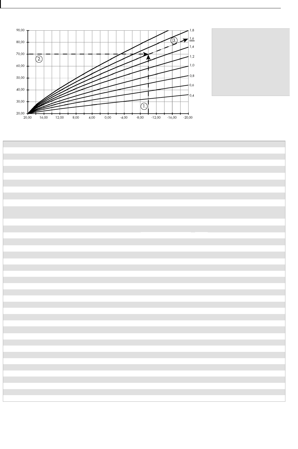
Maximum Solar Input via:
Yield sensor / collector sensor
Hot water at too high a temperature should be prevented
from entering the solar heat exchanger. The maximum in-
flow temperature can be measured via two different tem-
perature sensors:
Via the collector sensor: the maximum allowable collector
water temperature (110 – 115
0
C) which can enter the so-
lar heat exchanger is calculated from the lower thermal
store temperature.
Via the yield sensor: the maximum allowable collector wa-
ter temperature which can enter the solar heat exchanger
is measured at the yield sensor (heat exchanger inflow).
Safety shut down of the solar pump will occur when the
temperature exceeds 100
0
C at the yield sensor or 140 °C
at the collector sensor.
ADVICE:
If the yield measuring sensor is not installed in the solar
circuit the maximum inflow temperature must not be
measured at the yield sensor. In this case the „Maxi-
mum Solar Input via: collector sensor“ setting must be
selected and set.
Maximum Solar Input temporarily 120 °C
: Yes / No
Setting this function allows a maximum temperature of 120
°C for 5 minutes, although this temperature is only allowed
up to 50 times in a year.
ATTENTION:
This function is only suitable for systems which are de-
signed to withstand these short term high tempera-
tures. This function should not be used with low pres-
sure thermal stores (e.g. CONUS-Thermal Stores.
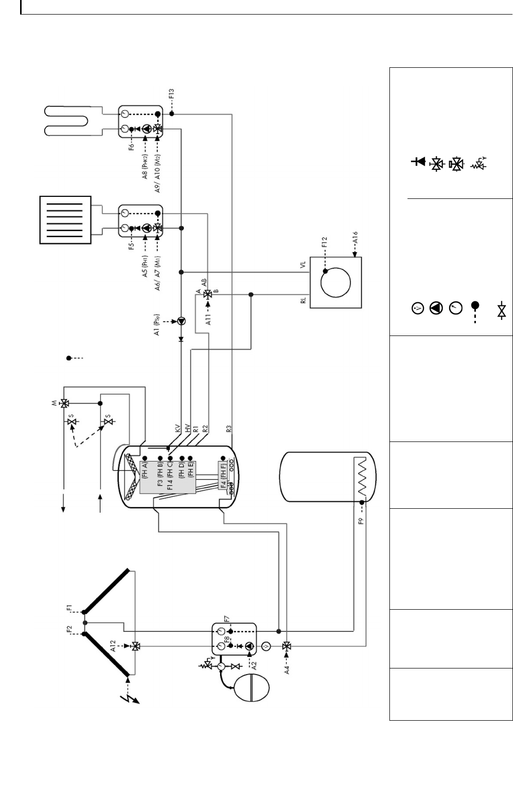
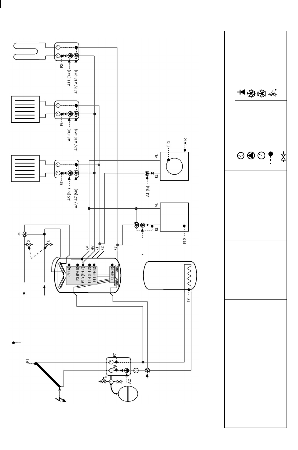
Only for CONUS Systems:
The following function is used to control systems in which a
hot water heat exchanger in the thermal store is used to
raise the temperature of the return flow.
Hot Water Back up Heating via the Regu-
lator: Yes / No
Hot water back up heating should be controlled using
CONTROL 601/701 „Return Flow Temperature Raising“
variation. The „Back up heating via CONTROL“ option is
set to „Yes“. While back up heating the demanded hot wa-
ter the return flow temperature raising function will be in-
terrupted in order to prevent an hydraulic short circuit.
Raising the temperature of the return flow is similarily dis-
continued during summer operation or when the heat limits
are exceeded.
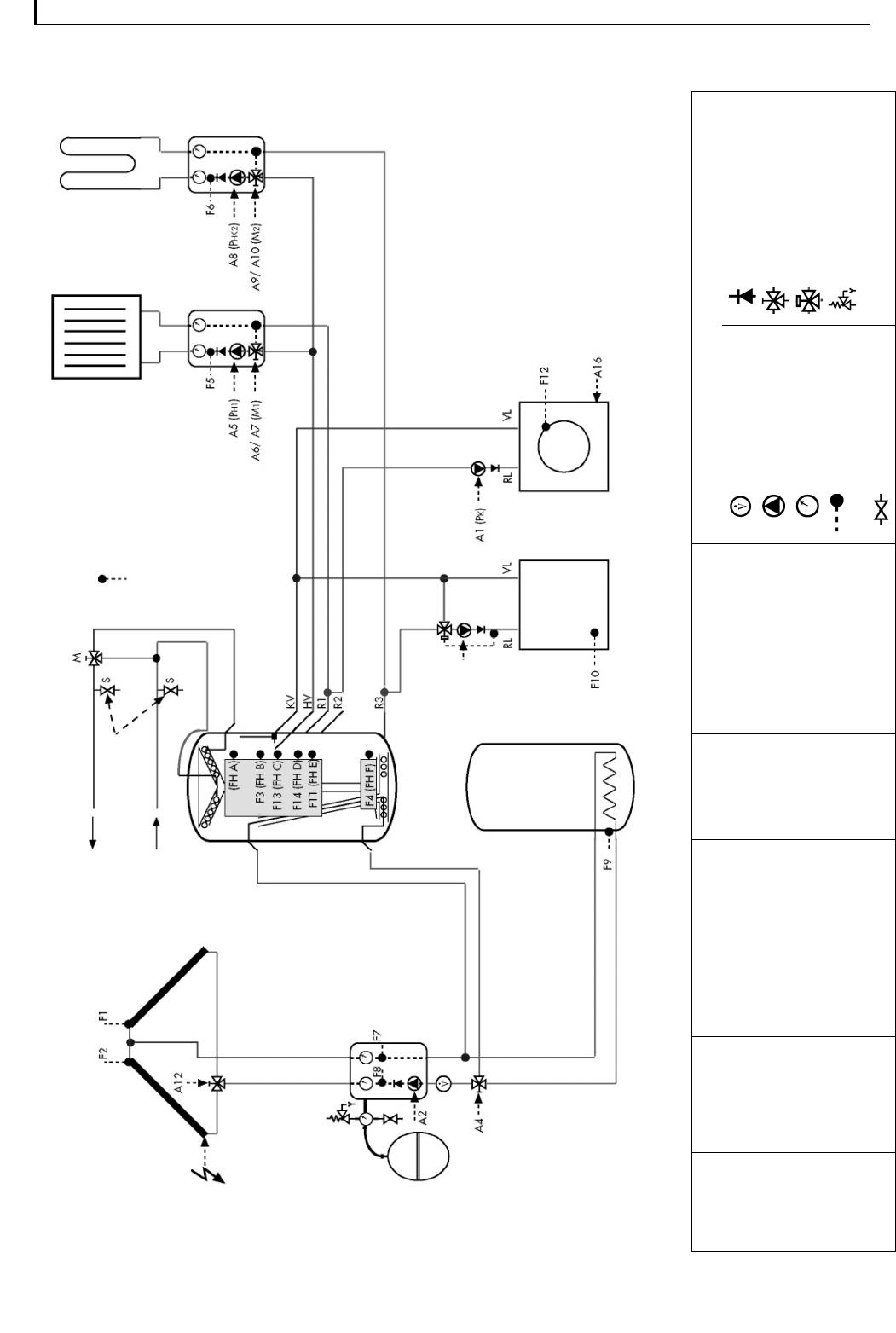
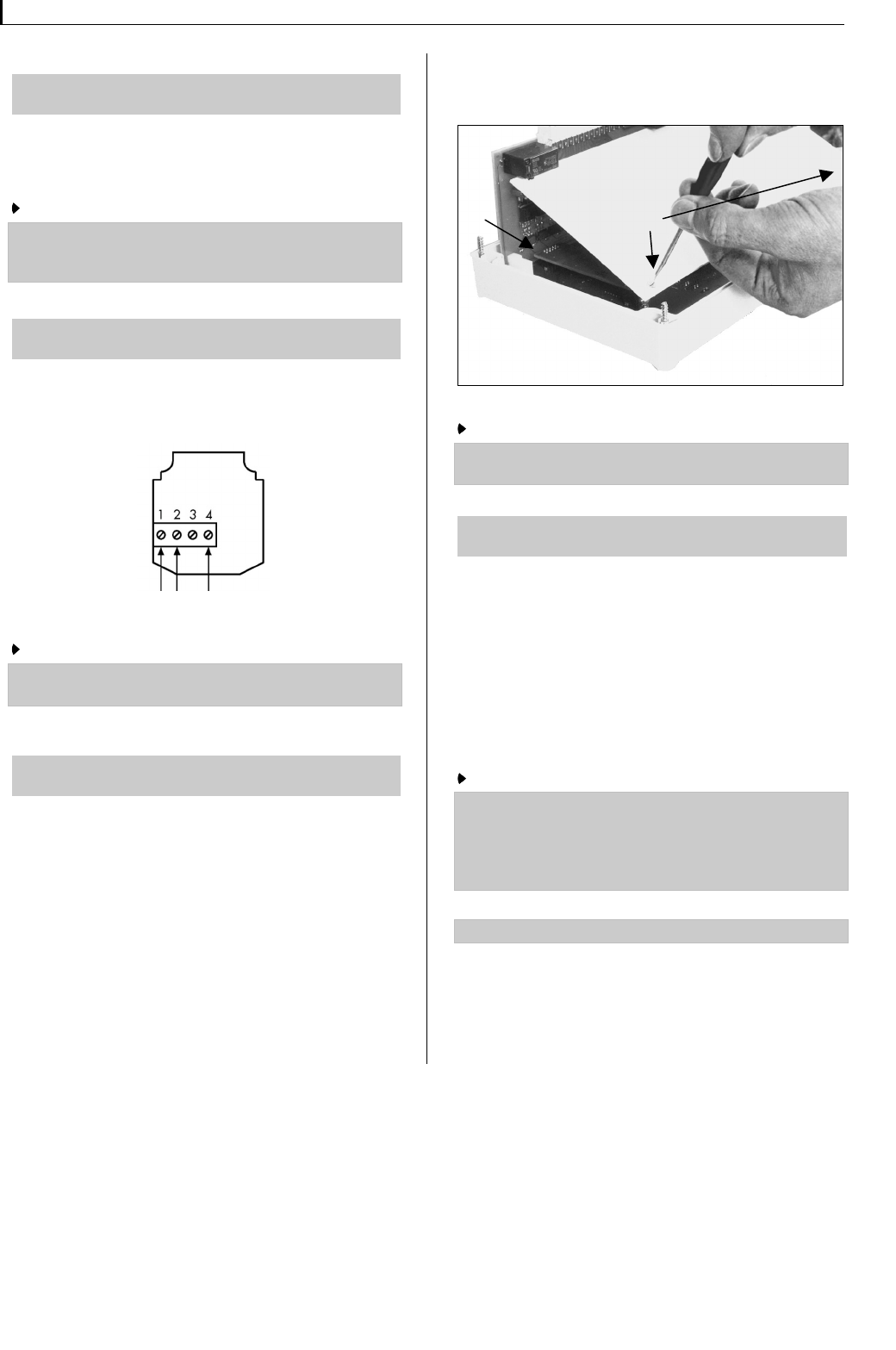
2.3 Solar Thermal System Operating Functions
(Solar Input Data)
Main Menu 12:34
Solar Input Data
The microprocessor controlled CONTROL 601 and 701
regulators have been developed to enable the optimal
functioning and operational safety of the Consolar Thermal
Stores. The regulators can also be used with other solar
thermal systems. The regulators allow intelligent utilization
of differing insolation and weather conditions by automati-
cally switching between three operating levels depending
on the solar loading.
2.3.1 Solar Pump Operation
Top loading (Stratification loading function): In good
weather conditions the full volume of the solar circuit water
is only circulated without interruption once the collector
minimum temperature (top loading temperature) has been
reached. The CONTROL 601/701 automatically calculates
the top loading temperature (hot water target temperature
+ 5K). The hysteresis is set at 2 K in the factory. The hot
water is, therefore, stratified loaded at the top of the Con-
solar Thermal Store at a temperature between 2 and 5K
lower.
Intermittent operation: If the solar insolation isn’t sufficient
to heat the collector to the top loading temperature, the
regulator will switch to intermittent solar pump operation.
That is the CONTROL 601/701 regulator waits for a set
period of time while the collector warms up. After this pre-
determined period the regulator switches on the solar
pump if the top loading temperature has not already been
reached in the meantime and already caused the solar
pump to run. The intermittent pump running time is such
that the collector contents are circulated approximately
once. The pre-warmed water is stored in the stratified lay-
ers of either the middle or lower regions of the Consolar
thermal store via an automatic valve. Useful water tem-
peratures for immediate use can be achieved more quickly
with the intermittent pump operation than by pure tem-
perature difference regulation. In summer this prevents the
need for back up heating using with the boiler.
Pre-heating: In winter, spring and autumn, if the solar in-
solation is insufficient to meet the hot water demand with-
out using the boiler, the regulator switches to pre-heating
mode. The solar heated water is then used to pre-heat the
water in the heating circuit buffer region.
Switch to Winter Operation: 0...60 °C
The heating circuit temperature at which the solar regula-
tor switches to winter mode can be set here. The solar
pump will then operate using only temperature difference
regulation. The switch over to winter operation is con-
trolled in the different system variations by either the heat-
ing inflow or return flow temperature sensors.