Table of Contents.......................................................................................................................................3
List of Figures.............................................................................................................................................8
List of Tables............................................................................................................................................10
About this Manual....................................................................................................................................13
Typefaces, Common Phrases & Terms__________________________________________________________13
Autopilot Operation: Maintaining a Heading______________________________________________________16
Wind and Current Effects____________________________________________________________________17
Autopilot Operation: Following a Track – NAV Mode_______________________________________________18
Autopilot Operation: Following a Track – AUTO/ALC Mode__________________________________________19
Power Steer_______________________________________________________________________________19
System Overview......................................................................................................................................23
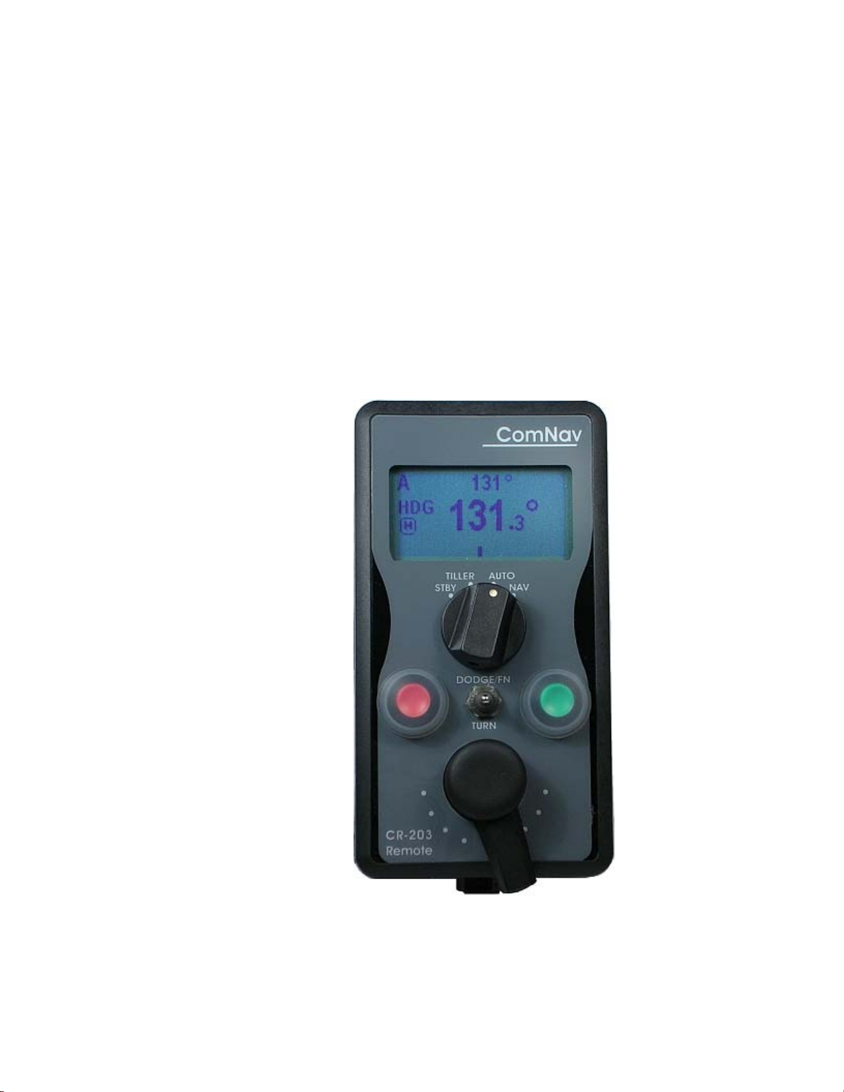
Control Head______________________________________________________________________________24
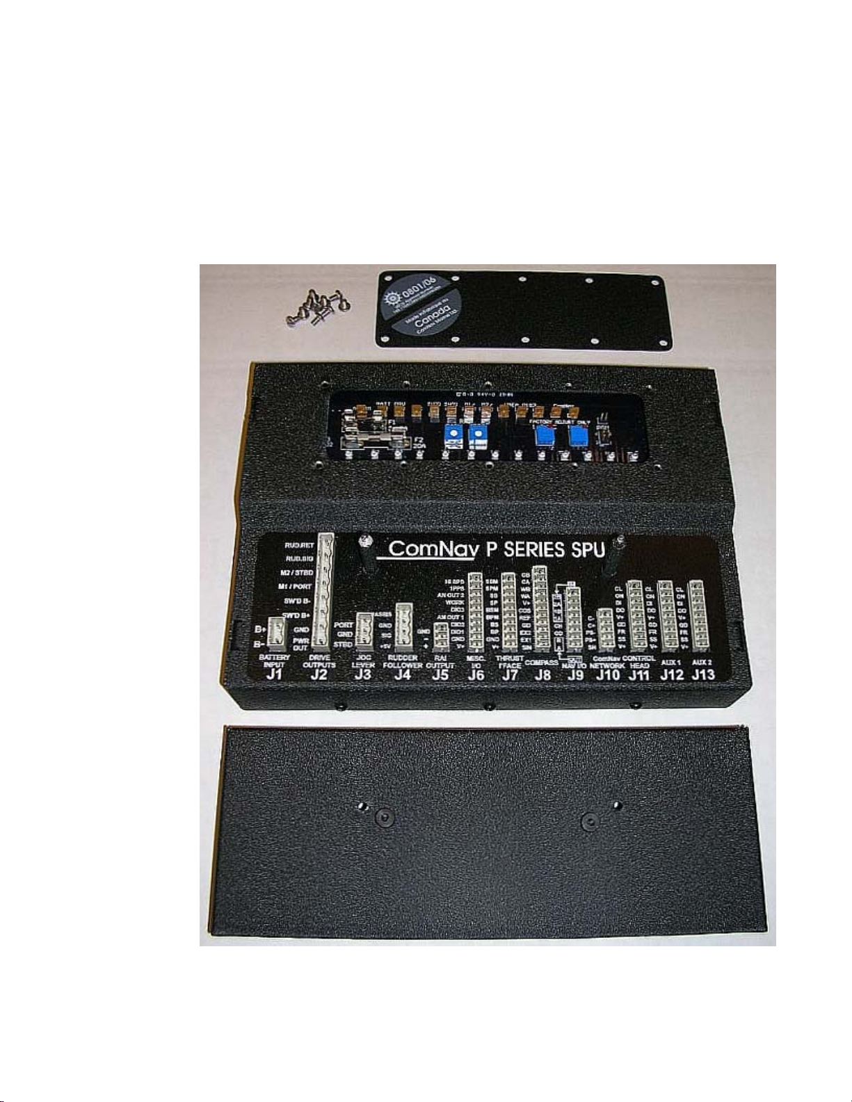
Signal Processor Unit_______________________________________________________________________25
Figure 2 – Heading Change in AUTO Mode...............................................................................................................17
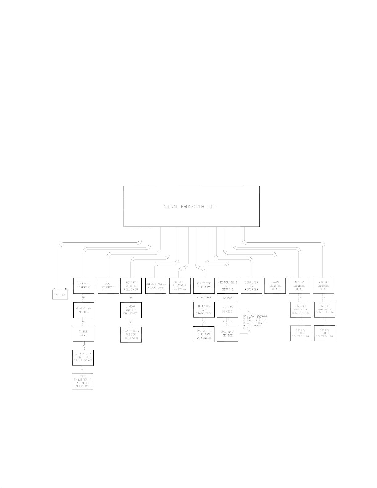
Figure 3 – Admiral P3 System Block Diagram............................................................................................................23
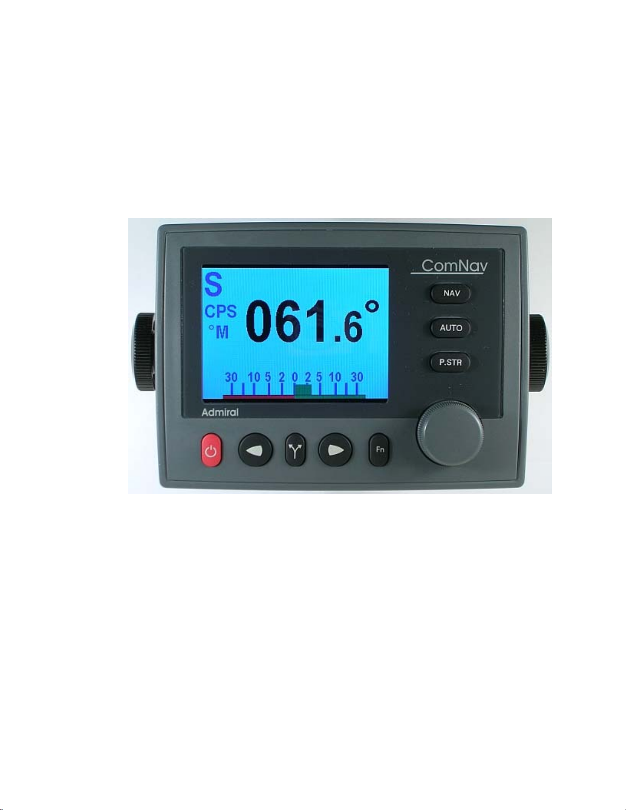
Figure 4 – Control Head..............................................................................................................................................24
Figure 5 – The Admiral P3 SPU with Wiring & Diagnostic Covers Removed.............................................................25
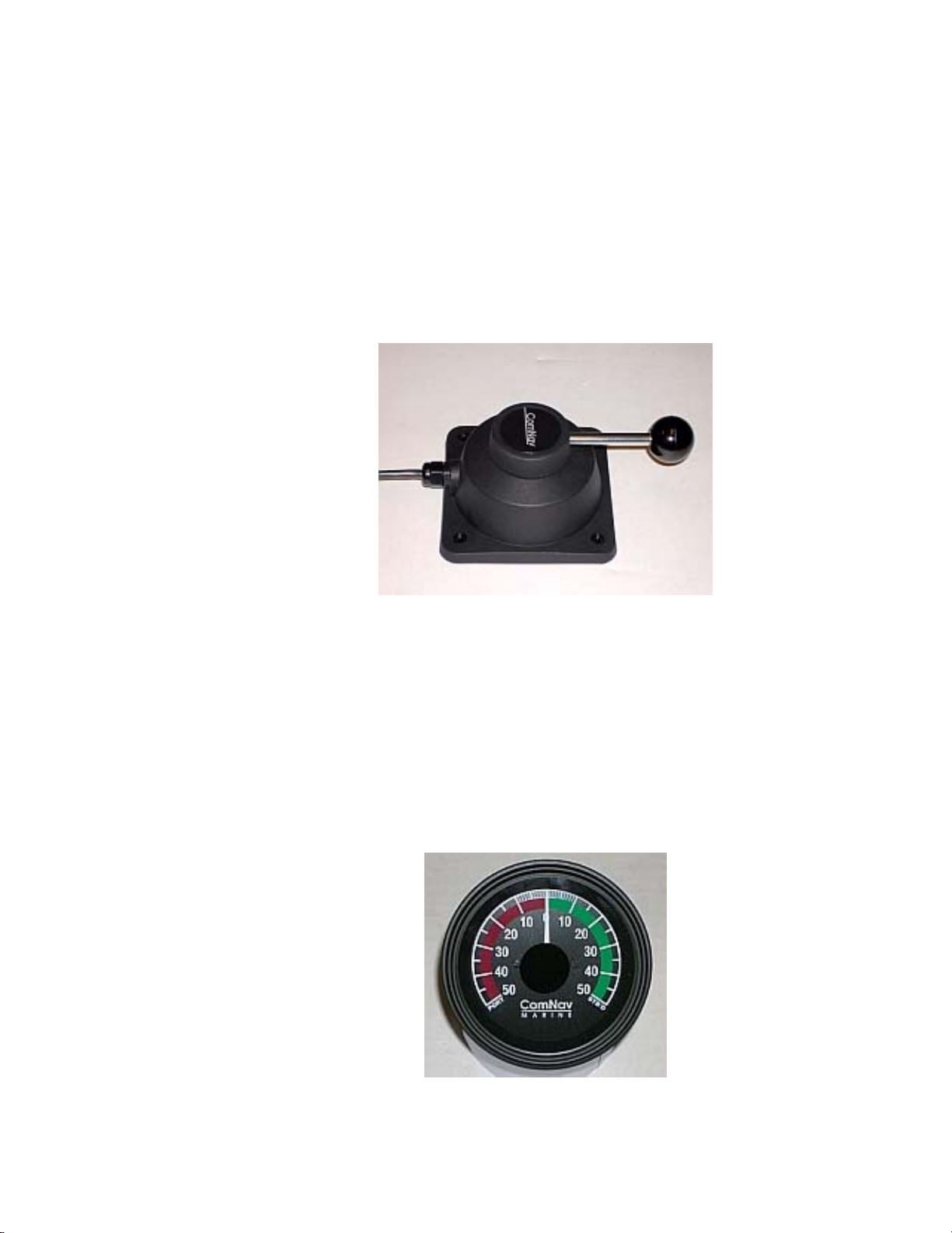
Figure 16 – Jog Lever..................................................................................................................................................33
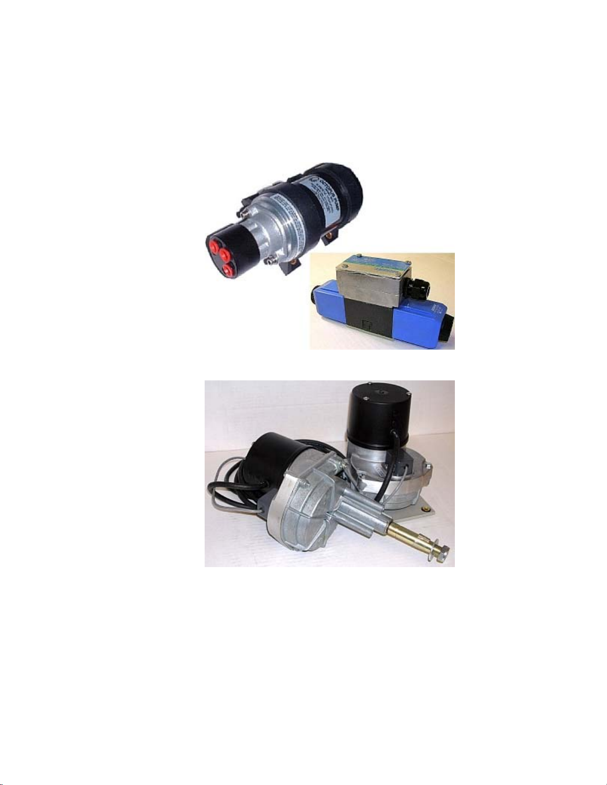
Figure 19 – Drive Boxes to meet all needs.................................................................................................................35
Figure 25 – Typical Battery Connection to SPU..........................................................................................................48
Figure 26 – Typical Battery Connection to Drive Boxes..............................................................................................49
Figure 27 – Reducing Supply Voltage Losses............................................................................................................49
Figure 28 – Wiring Connections for Control Head, Handheld Remotes, and Fixed Remotes....................................50
Figure 29 – Wiring Connections for Jog Levers..........................................................................................................51
Figure 30 – Wiring Connections for Four-Way Valves with Jog Levers......................................................................51
Figure 31 – Wiring Connections for Analog Compasses.............................................................................................52
Figure 32 – Wiring Connections for 45° Compass Transducer...................................................................................52
Figure 33 – Wiring Connections for Rudder Followers................................................................................................53
Figure 34 – Wiring Connections for Rudder Angle Indicators.....................................................................................53
Figure 35 – Wiring Connections for Reversing DC Motors.........................................................................................54
Figure 36 – Wiring Connections for Linear Actuators or Mechanical Rotary Drives...................................................54
Figure 37 – Wiring Connections for Shunt Field Reversing Motors............................................................................55
Figure 38 – Wiring Connections for Standard Four-Way Solenoid Valves.................................................................55
Figure 39 – Wiring Connections for Constant Running Electric Pump........................................................................56
Figure 40 – Wiring Connections for Two-Speed Solenoid Valves...............................................................................56
Figure 41 – Wiring Connections for A.C. Solenoids....................................................................................................57
Figure 42 – Wiring Connections for Proportional Solenoid Valves..............................................................................57
Figure 43 – Wiring Connections for Isolation Amplifiers..............................................................................................58
Figure 44 – External Alarm, using SW'D B- Output.....................................................................................................59
Figure 45 – External Alarm, using SW'D B+ Output....................................................................................................59
Figure 46 – External Alarm, SW'D B- Output – with Power Fail Option......................................................................60
Figure 47 – External Alarm, SW'D B+ Output – with Power Fail Option.....................................................................60
Figure 49 – Connection to a PC with a DE-9 Connector.............................................................................................62
Figure 50 – Connection to a PC with a DB-25 Connector...........................................................................................62
Figure 51 – Power Off Sequence................................................................................................................................69
Figure 52 – Using the Control Head............................................................................................................................70
Figure 53 – A Typical Menu.........................................................................................................................................72
Figure 58 – External Alarm Type Configuration..........................................................................................................78
Figure 59 – Set Vessel Type.......................................................................................................................................80
Figure 60 – Move Rudder to Starboard.......................................................................................................................81
ComNav Admiral P3 Installation & Operation Table of Contents, Lists of Figures & Tables
Document PN 29010075 V3.1- 9 -
Figure 61 – Move Rudder to Port................................................................................................................................82
Figure 62 – Center the Rudder...................................................................................................................................82
Figure 73 – Standby Menu (pages 1 & 2).................................................................................................................100
Figure 74 – Typical Power Steer Mode Screen........................................................................................................102
Figure 75 – Power Steer Menu.................................................................................................................................103
Figure 76 – Typical Auto Mode Screen.....................................................................................................................104
Figure 77 – Auto Menu, pages 1 & 2........................................................................................................................105
Figure 78 – Guidelines for setting Rudder Gain........................................................................................................105
Figure 79 – Guidelines for setting Counter Rudder..................................................................................................106
Figure 80 – HI and LO Speed Icons (Left of Rudder Angle Indicator).....................................................................107
Figure 81 – NAV Mode (Normal Display)..................................................................................................................109
Figure 82 – Nav Menu, pages 1 & 2.........................................................................................................................110
Figure 83 – Autopilot Steering for Correction Set to "CTS"......................................................................................112
Figure 84 – Autopilot Steering for Correction Set to "XTE".......................................................................................113
Figure 85 – Response of Vessel to Large Cross-Track Error...................................................................................114
Figure 86 – Autopilot Steering for Correction Set to "Both"......................................................................................115
Figure 87 – NAV Mode, Alternate Display................................................................................................................117
Figure 88 – Jog Lever Activated Screen...................................................................................................................118
Figure 89 – WORK Mode Menu................................................................................................................................121
Figure 90 – WORK Mode Engaged..........................................................................................................................122
Figure 91 – Typical Special Turn Query...................................................................................................................124
Table 13 – General Specifications.............................................................................................................................155
Table 15 – User Settings...........................................................................................................................................173
ComNav Admiral P3 Installation & Operation
Document PN 29010075 V3.1- 11 -
Introduction
ComNav Admiral P3 Installation & Operation
Document PN 29010075 V3.1- 12 -
ComNav Admiral P3 Installation & Operation About This Manual
Document PN 29010075 V3.1- 13 -
About this Manual
This manual provides essential information for the safe and reliable operation of the
ComNav Admiral P3 Wheelmark Autopilot System. You are urged to read this manual in
its entirety before you use your autopilot for the first time, and to keep it handy until you
become thoroughly familiar with the operation of your autopilot.
Typefaces, Common Phrases & Terms
Throughout this manual, you will see a number of different typefaces used, and several
commonly-used words & phrases with very specific meanings, to describe concepts &
actions that are fundamental to the operation of the autopilot. Please take a moment to
become familiar with the following items:
Modes of Operation
Specific “modes of operation” are placed in bold uppercase lettering.
Example: POWER STEER mode.
Button
Admiral P3 Control Head buttons and controls are placed in uppercase lettering.
Example: the TURN button.
System Component
Specific System Components are capitalized.
Example: The Control Head, or a Fluxgate Compass
LCD Display
Text that appears in the LCD display is in quotation marks.
Example: “Waypoint Arrival”
press or momentary press
Press and release the indicated button.
double-press
Press and release the indicated button twice in rapid succession.
Although this sounds a little complicated, it is actually very easy to do. Many users
familiar with desktop computers perform a similar function when they “double-click” their
mouse pointer.
press and hold
Press and hold the indicated button for a minimum of one-half of a second.
This time delay is purposely programmed into the system’s response to some buttons, to
prevent casual or accidental activation of the button function. For example, pressing the
Fn button can, depending on system configuration, drastically alter the steering
performance of the Autopilot.
maintain
Hold the indicated button for as long as required to achieve a given result.
Example: To dodge an obstacle in the water, press either the PORT ARROW or
STARBOARD ARROW button, and maintain it in that position until the vessel has dodged
clear of the obstacle in its path.
ComNav Admiral P3 Installation & Operation About This Manual
Document PN 29010075 V3.1- 14 -
Manual Format
This manual has been formatted to be printed on both sides of the pages of the manual,
and on standard Letter-sized paper (8.5” x 11”). If you have obtained this manual as a
soft-copy, please note that it is in Adobe® Portable Document Format (“pdf”), and so may
be viewed & printed with Adobe Reader®, or compatible pdf-format viewers.
When printing this manual with Reader, you should select “duplex printing” (or the
equivalent term used by your printer’s software driver), in order to print it double-sided on
the paper. If your printer does not have built-in duplexing capability, you can still print this
manual double-sided by following the instructions that came with your printer for doing
“hand duplexing”.
ComNav Admiral P3 Installation & Operation How Autopilots Work
Document PN 29010075 V3.1- 15 -
How Autopilots Work
The purpose of this section is to briefly describe what an autopilot does and some of the
things you should expect when using an autopilot with your boat. The information in this
section can be applied in general to any ComNav autopilot, and is not specific to the
Admiral P3 Autopilot.
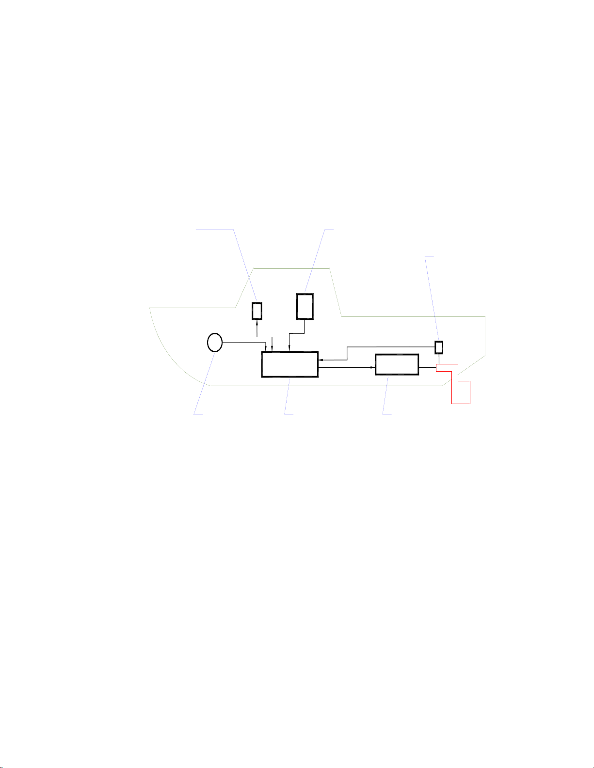
Basic Autopilot System
Figure 1 is a block diagram of the major components of an autopilot system.
COMPASS
READS THE VESSEL'S
ACTUAL HEADING AND
SENDS IT TO THE SPU
PROCESSOR (SPU)
CALCULATES THE RUDDER
POSITION NEEDED TO STEER
THE VESSEL ON THE DESIRED
HEADING, AND CONTROLS THE
STEERING SYSTEM
ACCORDINGLY
STEERING SYSTEM (ACTUATOR)
[HYDRAULIC RAM OR ELECTRIC MOTOR
WHICH IS MECHANICALLY CONNECTED
TO THE RUDDER]
MOVES THE RUDDER IN RESPONSE TO
CONTROL SIGNALS FROM THE SPU
RUDDER FOLLOWER UNIT (RFU)
[MECHANICALLY CONNECTED TO RUDDER]
MEASURES RUDDER POSITION AND SENDS
IT TO THE SPU
NAVIGATION DEVICES
[OPTIONAL]
SUPPLY NAVIGATION
INFOMRATION TO THE SPU
IN NMEA 0183 FORMAT
CONTROL HEAD
DISPLAYS STATUS AND HEADING
INFORMATION FROM THE SPU, AND
ALLOWS THE OPERATOR TO INPUT
STEERING COMMANDS & OPERATING
PARAMETERS
Figure 1 – Basic Autopilot System
The Compass indicates the direction in which the boat is pointed – often referred to as the
Actual Heading. Depending on the type of boat & installed equipment, the Compass may be
a magnetic compass, an electronic fluxgate compass, a gyroscopic compass, or a GPS
Compass. A reliable compass is absolutely vital to the autopilot – because, without a
compass, the autopilot has no way of knowing which way the boat is headed.
The actual heading is fed electronically from the Compass to the Processor (SPU) , which is
the heart of the autopilot. The SPU contains the microprocessor(s) & other electronic
hardware, and the sophisticated control software necessary to steer the boat on any Desired
Heading.
ComNav Admiral P3 Installation & Operation How Autopilots Work
Document PN 29010075 V3.1- 16 -
The Control Head, normally located in the wheelhouse, is the interface between the user
(that’s you …) and the autopilot. The Control Head displays information about what the
autopilot is doing. It has various controls (buttons &/or knobs) that allow the user to give
commands to the Autopilot.
The final part of the picture is the Steering System. In order for the autopilot to steer the
boat, there must be some a steering system (i.e., actuator) capable of moving the rudder
independently of the ship’s wheel. This might be a hydraulic ram that is connected to the
rudder post or tiller quadrant, or an electric motor connected to the steering cables.
Electronic signals from the SPU signal the steering system to move the rudder. Your
autopilot also will have a Rudder Follower Unit (RFU), a device that tells the SPU what
position the rudder is in at any given time.
Autopilot Operation: Maintaining a Heading
Say, for example, the autopilot was steering your boat Southwest, and you wished to change
direction to Southeast.
That’s easy – if you are using your ComNav Autopilot in AUTO mode.
To initiate the turn, you would turn the knob on the Control Head to set the Desired Heading
(as shown on the Control Head’s display screen) to 135° – i.e., Southeast.
The SPU then would compare this to the boat’s current Actual Heading of 225° (Southwest),
as indicated by the Compass, and determine that the Desired Heading is 90° to Port of the
Actual Heading. This in turn would cause the SPU to send a signal to the steering system to
move the Rudder to Port – so that the boat turns to Port. The SPU verifies that the Rudder
has moved by reading its position from the Rudder Follower Unit.
As the boat turns, the difference between the Desired Heading and the Actual Heading gets
smaller, and as it does, the SPU then starts to ‘back off” the rudder – i.e., move it back to
centre – so that the boat does not overshoot the Desired Heading.
Eventually, the Actual Heading will match the Desired Heading. The SPU will keep steering
the boat on a heading of 135°, until new instructions are received from the Control Head.
Figure 2 shows a vessel making that Southwest-to-Southeast turn in AUTO mode.
ComNav Autopilots provide an important safety feature in AUTO mode: when you first select
the mode, the autopilot will use the current Actual Heading as the Desired Heading. This
feature prevents the autopilot from executing an unexpected turn when you first select AUTO
mode.
ComNav Admiral P3 Installation & Operation How Autopilots Work
Document PN 29010075 V3.1- 17 -
Autopilot is steering vessel
on a heading of 225° (SW)
Autopilot responds to the
change in desired heading
Operator selects new
desired heading of 135° (SE)
by moving the rudder to
Port -- vessel begins to turn
As the actual heading
approaches the new desired
heading, the Autopilot starts
to move the rudder back
towards mid-ships position
then straighten out
the new heading slightly,
Autopilot to "over-shoot"
Typical response is for the
heading of 135° (SE)
the vessel on the new
Autopilot is now steering
N
Figure 2 – Heading Change in AUTO Mode
Wind and Current Effects
If your boat encounters a crosswind, and/or a tidal current, at some angle to the Desired
Heading, it will be constantly pushed away from that heading, in the direction of the wind or
current. So the autopilot will constantly be making course corrections.
As that condition persists, the SPU will gradually begin to maintain the rudder a few degrees
to Port or Starboard of the centred position, to counter the effect of wind, and/or current. This
feature, known as trim, will keep your boat pointed in the right direction, despite the wind or
current.
However, one side-effect of trim is that your boat may not follow the Track you want – it will
maintain your Desired Heading, but the track will “slip” sideways in the direction of the
crosswind and/or current. This potential problem can be solved by using another mode that
ComNav Autopilots provide: NAV mode, described next.
ComNav Admiral P3 Installation & Operation How Autopilots Work
Document PN 29010075 V3.1- 18 -
Autopilot Operation: Following a Track – NAV Mode
So far, we have seen how an autopilot operates in AUTO mode: a new desired Heading must
be selected on the Control Head each time you wish to change direction. This is handy for
short trips or when you know the direct course to your objective.
But for longer trips, which might involve a number of legs at different headings, it would be
useful to be able to have your autopilot steer your boat along all the legs, in sequence.
ComNav autopilots allow you to do just that, with NAV mode.
Before using NAV mode:, the autopilot must be connected to an external source of navigation
information (commands & data) – such as a chart plotter, or a Navigation program running on
a PC. A source of position data is required, too; it may be built into the external Navigation
System, or it may be another device or system: a GPS receiver (such as a ComNav Vector
GPS Compass), a LORAN C receiver, etc.1
ComNav Autopilots implement the industry-standard NMEA 0183 protocol for reception &
transmission of navigation information. Fortunately, almost all of today’s Navigation Systems
& Devices do comply with NMEA 0183, so interfacing those systems & devices to a ComNav
autopilot is relatively simple.
A long passage will consist of a series of waypoints, which are specific locations on the
Earth’s surface (hopefully on the water!) defined by their Latitude & Longitude. These
waypoints are entered into the external Navigation System by the user. That system
determines the current location of the boat (from the source of position data), and then
calculates the course that must be steered in order to reach the next waypoint.
When the Autopilot is switched into NAV mode, it begins to look for some specific navigation
information from the Navigation System: the course to steer to the next waypoint, and the
Cross-Track error (which is the distance from the boat to the desired Track from the last
waypoint to the next one). Using these two pieces of information, the autopilot steers the
boat on the shortest possible course to the next waypoint.
Crosswinds and/or currents are compensated for automatically each time the Navigation
System updates the cross-track error. This is why NAV mode is the answer to the “track slip”
problem that can occur in AUTO mode, when a crosswind/current exists.
When a waypoint is reached, the Navigation System sends the SPU the next set of
navigation information – for the next waypoint – and the SPU then turns the boat to head to
that next waypoint.
When the last waypoint is reached, the boat typically (depending on how the Navigation
System is set up) will orbit that waypoint, until the autopilot either is switched out of NAV
mode or is given new navigation information by the user, via the Navigation System.
Because the boat will turn automatically turn – without input from the user – at each waypoint,
when planning the trip it is crucial that the user verify that there will be sufficient room to
execute the turn at each waypoint.
The autopilot can be set to alert he user – by activating an alarm – as the boat nears a
waypoint.
1 … all such external devices are in general referred to in this manual with the generic term Navigation System.
ComNav Admiral P3 Installation & Operation How Autopilots Work
Document PN 29010075 V3.1- 19 -
Autopilot Operation: Following a Track – AUTO/ALC Mode
Some ComNav autopilots – including the Admiral P3 – provide another way to keep your boat
on a specific Track: Automatic Leeway Correction. This feature – an element of the P3’s
Intelligent Steering Technology – can be turned on in AUTO mode.
ALC is similar to NAV mode, in that it uses NMEA 0183 Latitude/Longitude data to sense if
the boat is following the desired Track.
Unlike NAV mode, however, the Admiral P3 only needs Latitude/Longitude data in
AUTO/ALC mode. It does not need Cross-Track error data from the external Navigation
System, nor that there be any waypoints set in the system. The P3’s IST feature calculates
the Cross-Track error on its own, using the desired heading active at the point in time when
AUTO/ALC mode is first engaged.
Power Steer
Most ComNav autopilots have a POWER STEER mode, which provides a way for the user to
directly control the rudder. Basically, the autopilot acts as a sort of “electronic steering
wheel”, allowing the operator to steer the vessel manually, in a similar way as when using a
standard manual steering wheel or tiller, but from the autopilot’s Control Head or any remote
controls it is equipped with.
Steering, when using the autopilot in this mode, is done with two buttons and/or a knob on
the Control Head. One button, and/or a clockwise turn of the knob, will move the rudder to
Starboard; the other button, and/or a counter-clockwise turn of the knob, will move the rudder
to Port.
Using the buttons/knob, the rudder can be placed in any desired position where it will remain.
This feature is useful when docking or manoeuvring, because the person steering the vessel
can take their hands off the controls between rudder movements.
ComNav Admiral P3 Installation & Operation
Document PN 29010075 V3.1- 20 -
ComNav Admiral P3 Installation & Operation
Document PN 29010075 V3.1- 21 -
System Overview
ComNav Admiral P3 Installation & Operation
Document PN 29010075 V3.1- 22 -
ComNav Admiral P3 Installation & Operation System Overview
Document PN 29010075 V3.1- 23 -
System Overview
This chapter gives a brief description of the major elements of the Admiral P3 Wheelmark
Autopilot System, their functions, and their relationships to each other.
Below is a block diagram of a typical example of the Admiral P3 system, showing the
interconnections between the elements of the system:
•The Signal Processor Unit (SPU)
•The Main Control Head
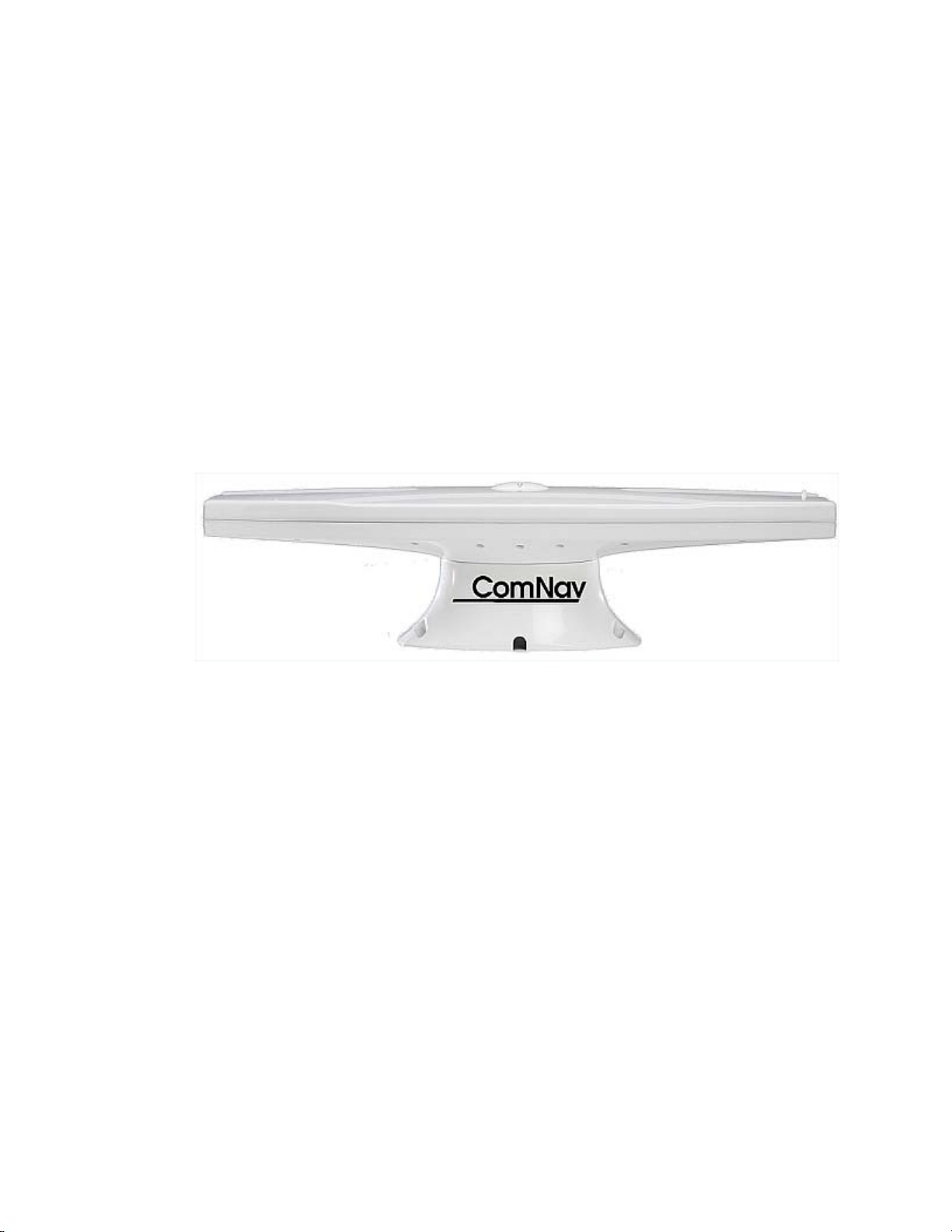
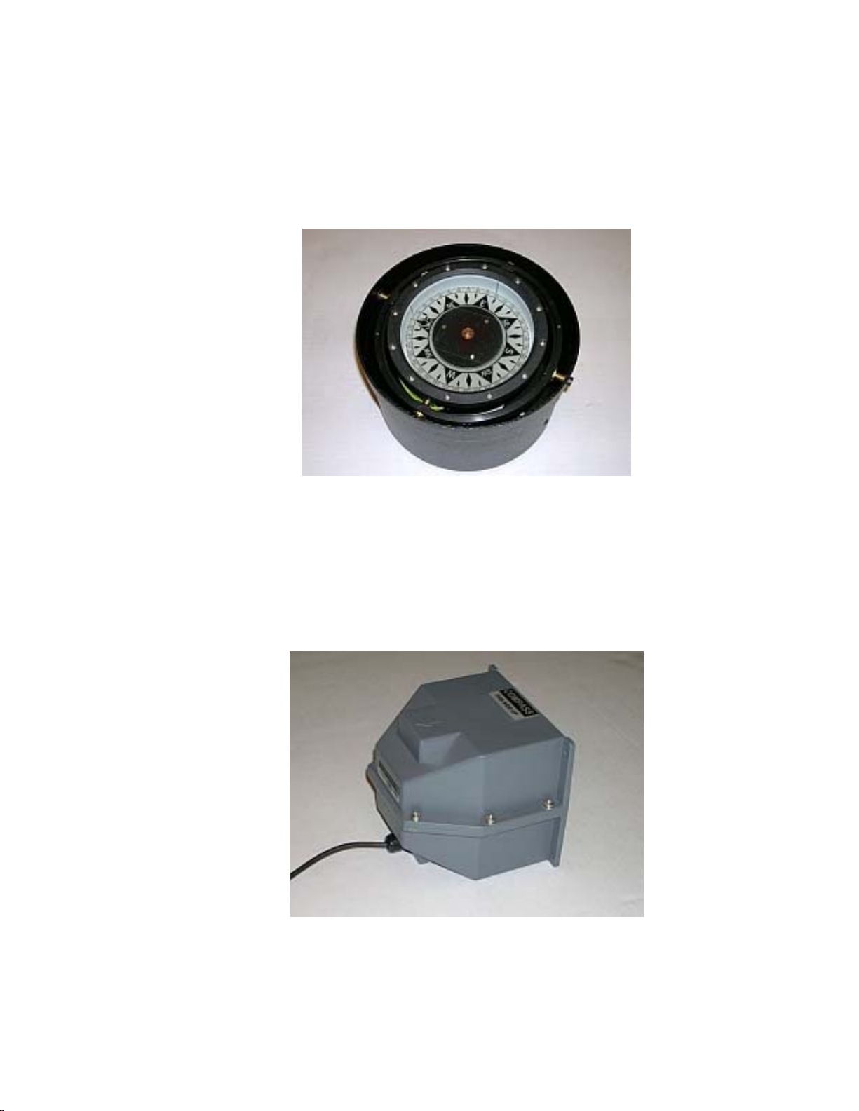
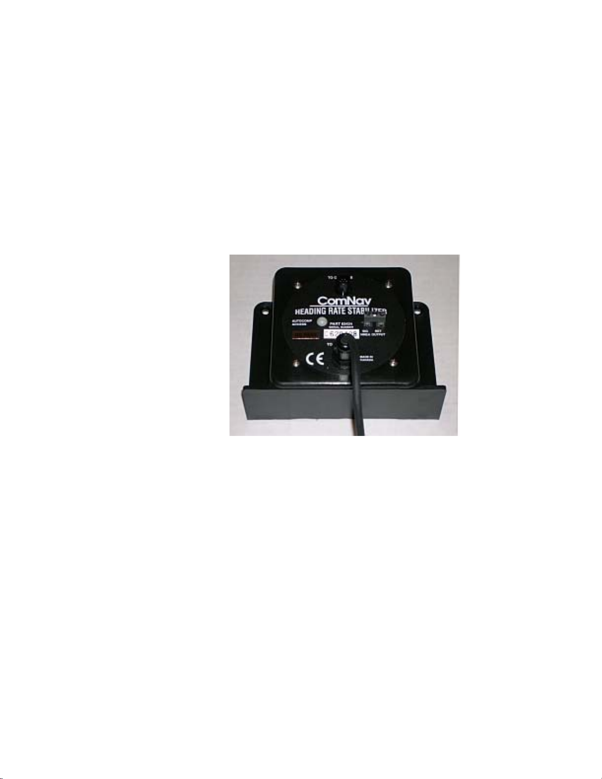
•A Compass or other Heading Sensor
•Solenoid(s), Reversing Motor, or Cable Drive, which move the Rudder
•The Rudder Feedback Unit
•Optional Auxiliary Control Head(s) & Remote Controls
Gebruikershandleiding.com neemt misbruik van zijn services uitermate serieus. U kunt hieronder aangeven waarom deze vraag ongepast is. Wij controleren de vraag en zonodig wordt deze verwijderd.
Product:
Spelregels forum
Om tot zinvolle vragen te komen hanteren wij de volgende spelregels:
lees eerst de handleiding door;
controleer of uw vraag al eerder door iemand anders is gesteld;
probeer uw vraag zo duidelijk mogelijk te stellen;
heeft u een probleem en al geprobeerd om dit op te lossen, vermeld dit erbij aub;
heeft u een oplossing gekregen van een bezoeker dan horen wij dat graag in dit forum;
wilt u een reactie geven op een vraag of antwoord, gebruik dan niet dit formulier maar klik op de knop 'reageer op deze vraag';
uw vraag wordt direct op de website gezet; vermijd daarom persoonlijke gegevens in te vullen;
Belangrijk! Als er een antwoord wordt gegeven op uw vraag, dan is het voor de gever van het antwoord nuttig om te weten als u er wel (of niet) mee geholpen bent! Wij vragen u dus ook te reageren op een antwoord.
Belangrijk! Antwoorden worden ook per e-mail naar abonnees gestuurd. Laat uw emailadres achter op deze site, zodat u op de hoogte blijft. U krijgt dan ook andere vragen en antwoorden te zien.
Abonneren
Abonneer u voor het ontvangen van emails voor uw ComNav Admiral P3 bij:
nieuwe vragen en antwoorden
nieuwe handleidingen
U ontvangt een email met instructies om u voor één of beide opties in te schrijven.
Ontvang uw handleiding per email
Vul uw emailadres in en ontvang de handleiding van ComNav Admiral P3 in de taal/talen: Engels als bijlage per email.
De handleiding is 4,57 mb groot.
U ontvangt de handleiding per email binnen enkele minuten. Als u geen email heeft ontvangen, dan heeft u waarschijnlijk een verkeerd emailadres ingevuld of is uw mailbox te vol. Daarnaast kan het zijn dat uw internetprovider een maximum heeft aan de grootte per email. Omdat hier een handleiding wordt meegestuurd, kan het voorkomen dat de email groter is dan toegestaan bij uw provider.
Stel vragen via chat aan uw handleiding
Stel uw vraag over deze PDF
Uw handleiding is per email verstuurd. Controleer uw email
Als u niet binnen een kwartier uw email met handleiding ontvangen heeft, kan het zijn dat u een verkeerd emailadres heeft ingevuld of dat uw emailprovider een maximum grootte per email heeft ingesteld die kleiner is dan de grootte van de handleiding.
Er is een email naar u verstuurd om uw inschrijving definitief te maken.
Controleer uw email en volg de aanwijzingen op om uw inschrijving definitief te maken
U heeft geen emailadres opgegeven
Als u de handleiding per email wilt ontvangen, vul dan een geldig emailadres in.
Uw vraag is op deze pagina toegevoegd
Wilt u een email ontvangen bij een antwoord en/of nieuwe vragen? Vul dan hier uw emailadres in.