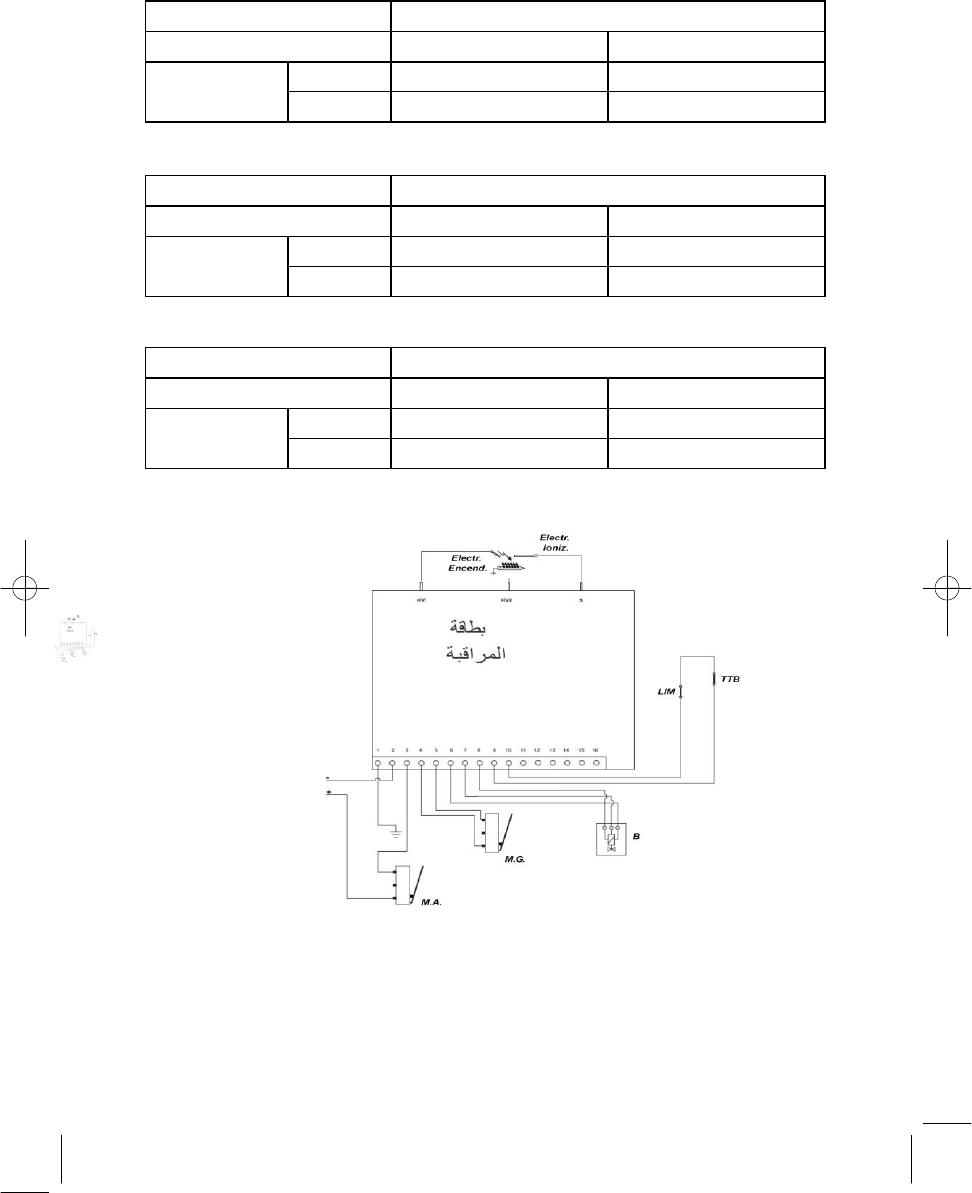
WIRING OUTLINE OF WATER HEATERS WITHOUT PILOT LIGHT..........................
14
OPTIMA
2
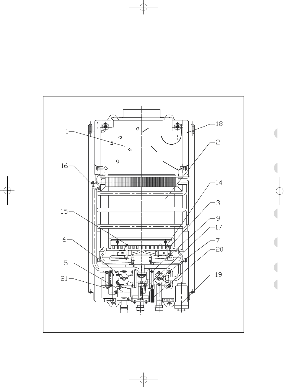
DESCRIPTION AND FEATURES BY MODEL
Your COINTRA water heater
has been designed and manufactured so that, through correct usage, you can enjoy the convenience of
hot water.
Depending on the model chosen, it consists of the following components (see table below).
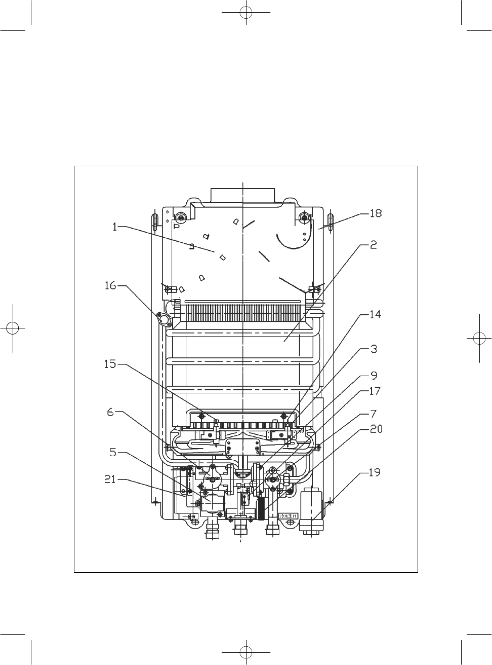
3
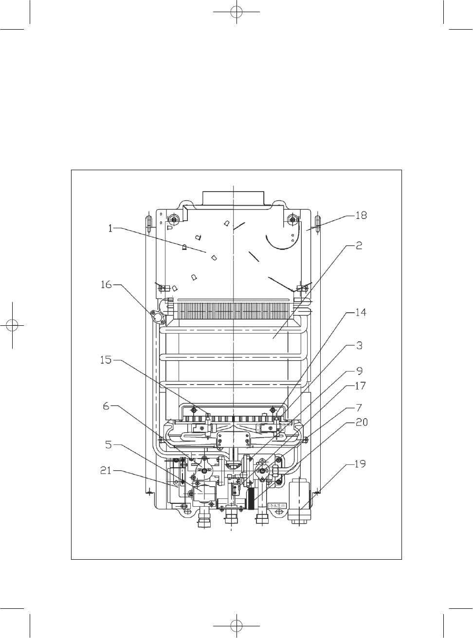
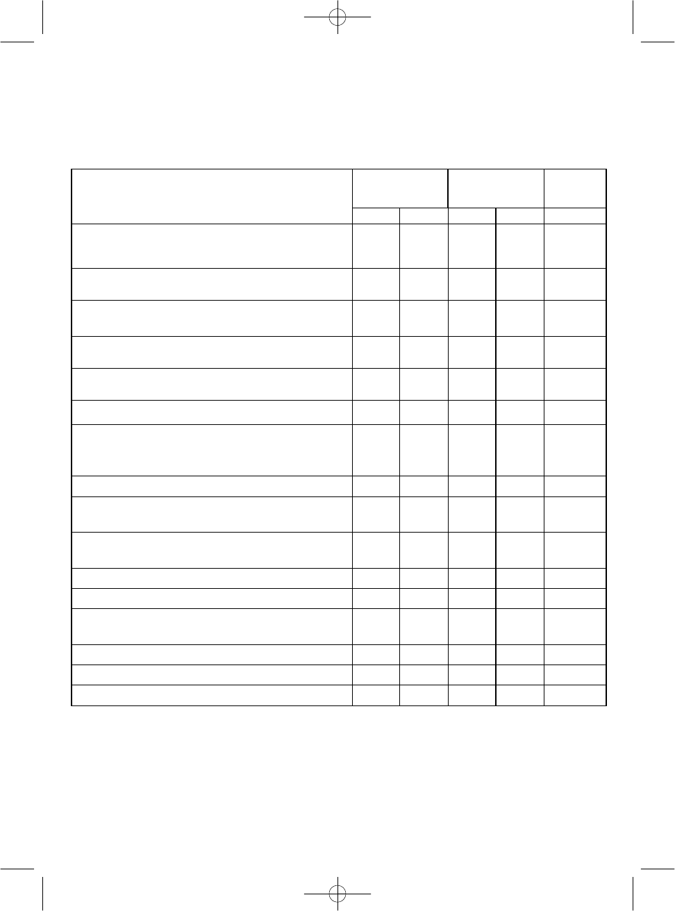
DEPENDING ON THE MODEL CHOSEN, THE WATER HEATER WILL COMPRISE THE
FOLLOWING COMPONENTS
FUNCTIONAL ASSEMBLIES
5
l/min models
8.9 kW
(127.5
Kcal/min
)
10
l/min models
17.8 kW
(255
Kcal/min
)
14l/min model
23,8 kW
(341 kcal/min)
COB 5
COB 5 x
COB 10
COB 10 x
COB 14
1.
Incorporated draught diverter.
Ensures proper combustion even when the draught changes in the burnt gas
evacuation duct (flue).
With its new design, the heater cover is free of gratings.
Yes
Yes
Yes
Yes
Yes
2. Heat exchanger
.
Pure electrolytic copper with a caloric coating that ensures the highest
possible heat transfer to water.
Yes
Yes
Yes
Yes
Yes
3. Burner
Advanced technology that takes full advantage of the gas consumed
Yes
Yes
Yes
Yes
Yes
5. Ignition safety valve
.
E
lectric system that only allows gas to leave the burners when the pilot light’s
presence ensures it is ignited
Yes
Yes
Yes
Yes
Yes
6.
Front gas control.
This can also be used to MANUALLY SELECT THE REQUIRED POWER.
Yes
Yes
Yes
Yes
Yes
7. Temperature selector.
Allows you to adjust the hot water temperature.
Yes
Yes
Yes
Yes
Yes
9.
Special hydraulic device
.
•
Automatically starts the water heating mechanisms each time a hot water
tap is turned on. This is a GUARANTEE at the same time as the gas passage is
only open when water circulates through the exchanger.
Yes
Yes
Yes
Yes
Yes
13. Hot water connection:
Flexible
Yes
Yes
Yes
Yes
Yes
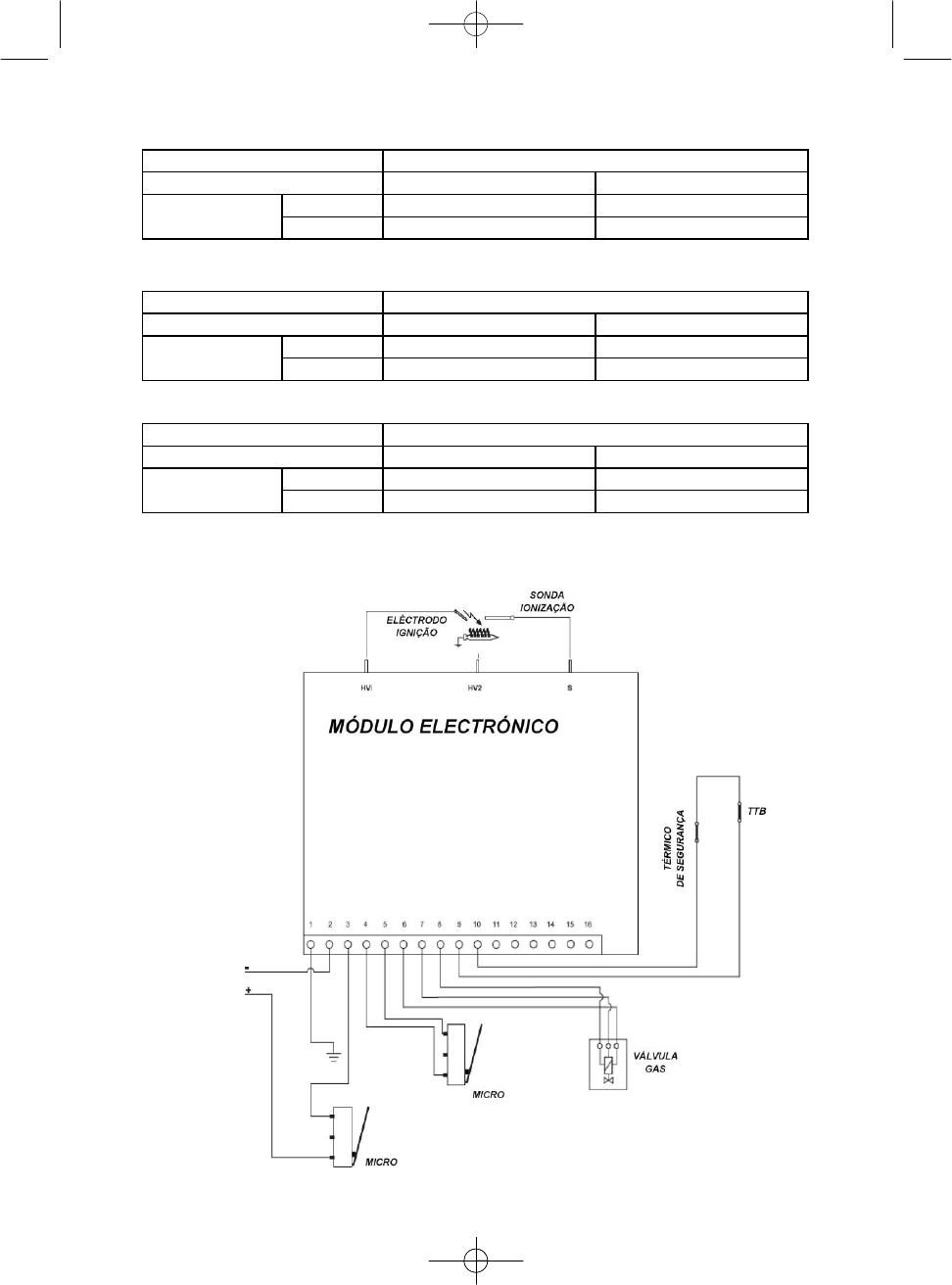
14. Electronic Ionisation probe.
Used to ensure the burner’s smooth operation through the ionisation
control.
(see figure
page
13)
Yes
Yes
Yes
Yes
Yes
15.
Electrode ignition.
Provides continuous sparks to ignite the burner
.
(see
figure
page 13)
Yes
Yes
Yes
Yes
Yes
16. Temperature restrictor thermostat.
Yes
Yes
Yes
Yes
Yes
17.
Ignition micro.
Yes
Yes
Yes
Yes
Yes
18.
Control device for gas evacuation
.
(TTB)
Disconnects the heater if the combustion gas outlet is obstructed.
Yes
no
Yes
no
Yes
19. Battery box.
Yes
Yes
Yes
Yes
Yes
20 . Drainage valve.
Yes
Yes
Yes
Yes
Yes
21.
Electronic
control module.
Yes
Yes
Yes
Yes
Yes
4
USER INSTRUCTIONS
ELECTRONIC WATER HEATERS (WITHOUT PERMANENT PILOT LIGHT)
-
Prior checks
1. Make sure hot water taps are turned off.
2. Turn on the gas to water heater stopcock that is located where gas is supplied to the appliance.
3. Check that the 1.5 V batteries are correctly installed according to polarity (+ and -) and the safety seal has been
removed.
4. Check that they are sufficiently charged for the water heater to function.
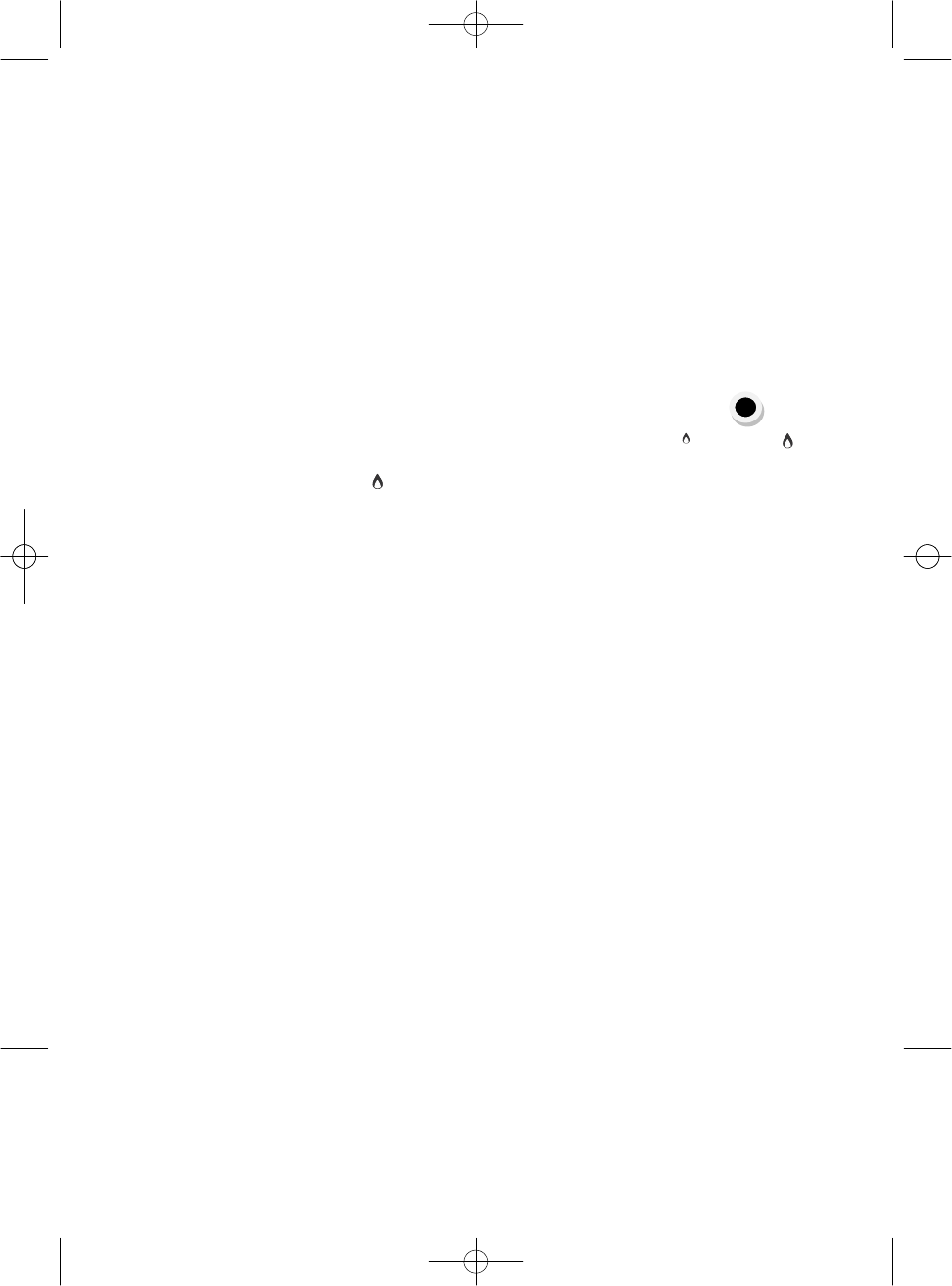
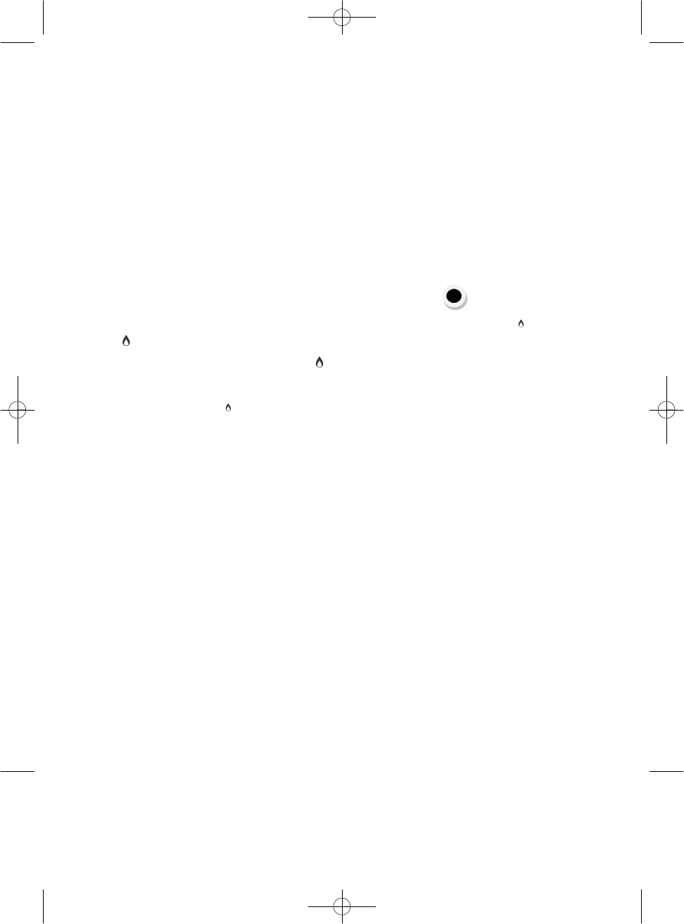
- Manual selection of Burner Power
To ignite the appliance, turn the gas knob from the position to one of the 2 minimum or
maximum positions.
The gas knob allows you to select the water heater power, minimum ( ) or maximum
( ), and intermediate positions according to the hot water intensity required. Turn the gas knob to
the position (large flame), the unit heats the water at full
power. If the temperature is too high, for example in summer or if a small volume of not very hot
water is required, turn the knob to the position(small flame), reducing the power (and gas
consumption) almost by half.
- Temperature selection
With the Temperature Selector you can easily gauge the water temperature by turning the selector to the right to
achieve a higher temperature, or to the left to obtain less hot water.
- Hot Water Service
- Once the previous settings have been selected, the water heater will start the process; turning on the hot water tap
will automatically generate continuous sparks through its ignition electrode and directly light the burner.
- All the electronic models have an ionisation probe, which is immersed in the flame to control
it.
- If for any reason an issue has occurred in the gas circuit and the probe does not detect the flame’s
presence, the ignition electrode will automatically generate sparks for a few seconds to ignite the
burner; in the event that the water heater does not turn on, it will be out of service.
- You must remove the cause or element that prevents the gas from reaching the water heater, for
example if the stopcock has been inadvertently turned off, worn out gas cylinder, etc.
5
- The water heater block is deactivated by turning on and off the hot water tap;
- If the cause is removed and the hot water supply is not re-established after turning on the hot water, repeat the
operation. Contact Technical Support if the anomaly persists.
- The flame’s presence in the burner is seen through the window on the cover.
- Turning off the water heater
To turn the water heater off, turn the gas knob again to the position
I
M
P
ORTA
N
T
NOTE
To protect the environment, deposit used batteries in containers
intended for this
purpose.
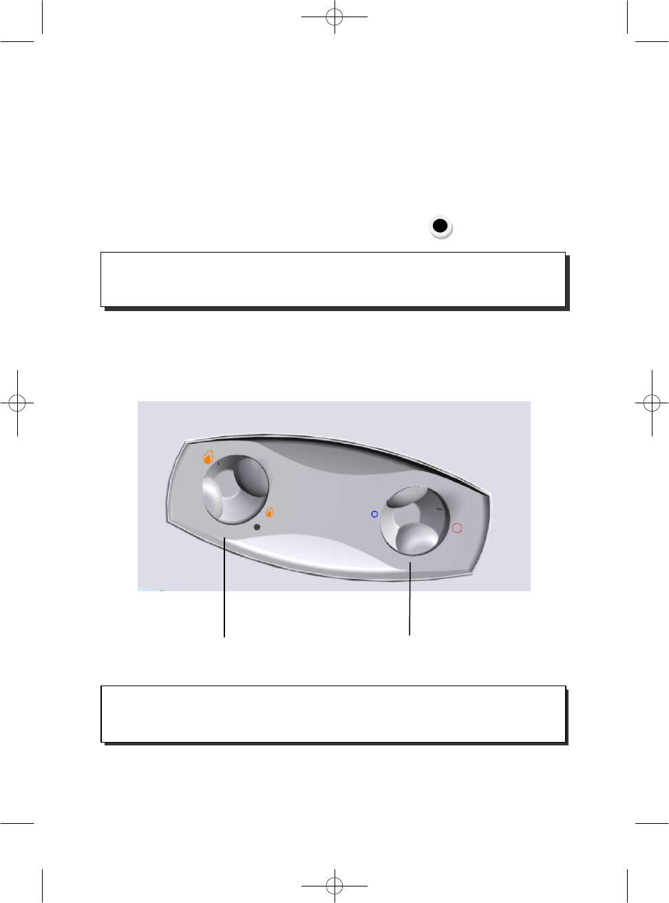
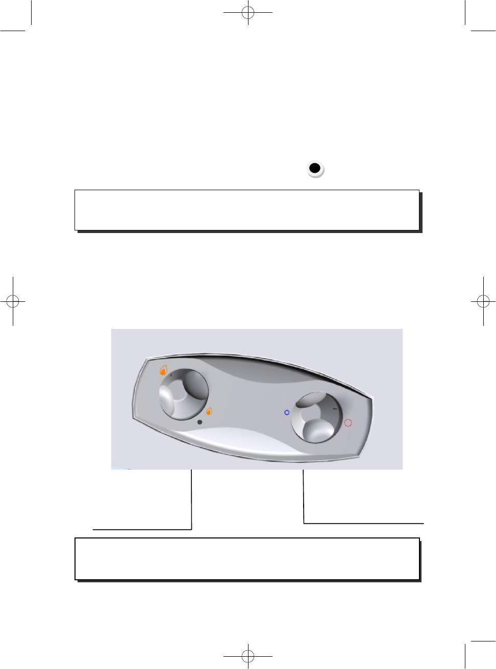
CONTROL PANEL OF
5- AND 10-LITRE WATER HEATERS
GAS KNOB
TEMPERATURE SELECTOR
VERY
IMPOR
T
A
NT
It is recommended that the installation’s stopcock is turned off when the unit is not being
used frequently
.
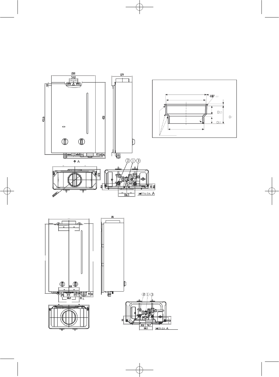
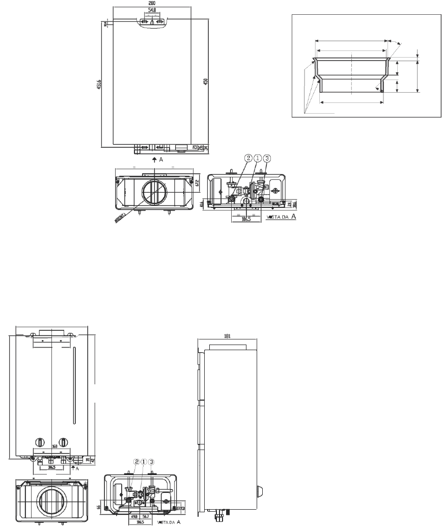
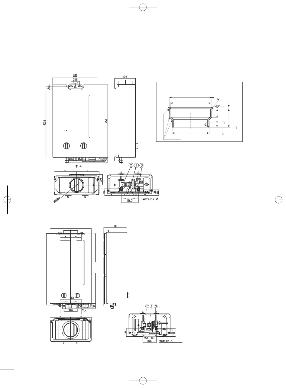
6
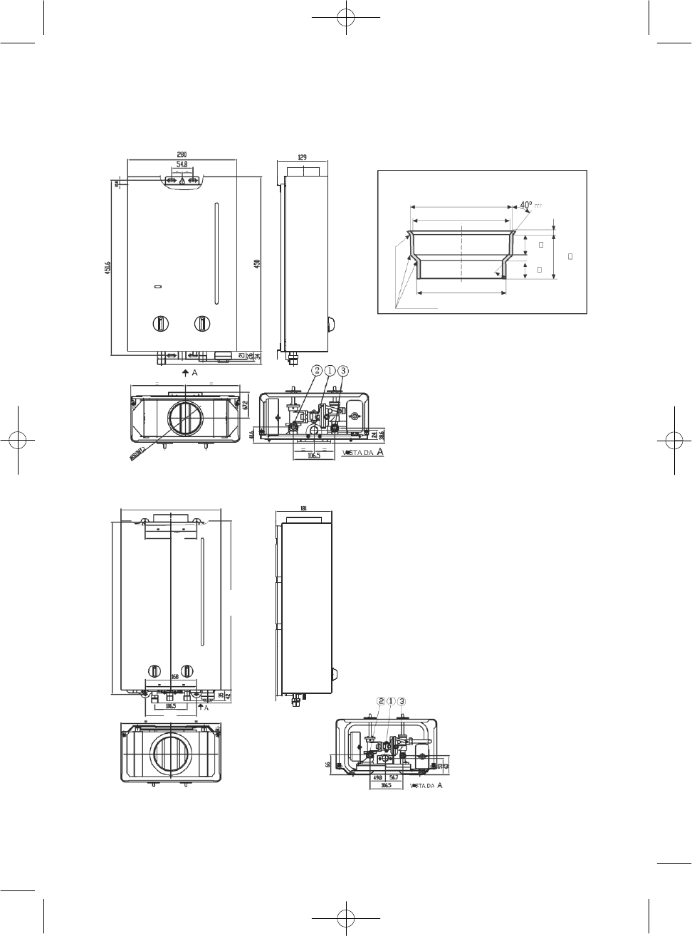
5-
l/min MODELS
WATER HEATERS WITHOUT PILOT LIGHT
COUPLER
ø
80
to
ø
100
ø
102.5
+0,5
INT
.
ø
101,5
+0,5
INT
.
~45º
ø
80,5
-0,5
EXT
.
R.
minimum
21
0,5
17
0,5
4,5
+0,5
44
1
Only install in evacuation ducts of
Ø
100 combustion products.
1
=
Hot water outlet
:
R
1/2”.
3
=
Cold water inlet
:
R
1/2”.
2
=
Butane/propane inlet
:
Ø
12
mm
ext.
Natural gas inlet:
Ø
15
mm
ext.
1
0-
l/min MODELS
1
=
Hot water outlet
:
R
1/2”.
3
=
Cold water inlet
:
R
1/2”.
2
=
Butane/propane inlet
:
Ø
12
mm
ext.
Natural gas inlet:
Ø
15
mm
ext.
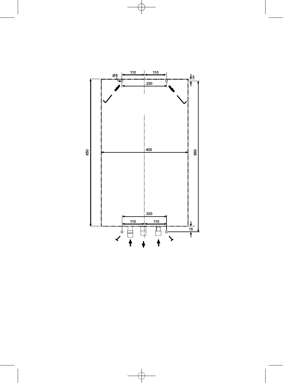
400 (14 L)
328 (10 L)
660 (14 L)
560 (10 L)
650 (14 L)
550 (10 L)
(*)
220 (14 L)
168 (10 L)
(*)
220 (14 L)
170 (10 L)
Ø130 mm
7
INSTALLATION INSTRUCTIONS
The water heater must be installed by a professional that holds an AUTHORISED GAS INSTALLER PERMIT.
The smooth
operation of your COINTRA water heater depends largely on it being installed CORRECTLY.
This task will be easier if you follow the guidelines below:
1.
MODEL, PREMISES AND LOCATION.
1.1. Pay particular attention to ensure the chosen water heater is suitable:
- To satisfactorily cover the facility’s hot water needs.
- For the intended gas (see water heater data plate).
- In relation to the water pressure in the network necessary for it to work (see specification table on page
12).
1.2. Ensure that the facility’s premises meets all the conditions required by the
Regulations.
1.3. Position the water heater as near to the hot water tap as possible, near the
sink but NEVER above the cooker. It should also be placed as near as possible
to the flue or the point where the pipe that disposes of burnt gases comes out.
2. PIPES.
2.1. Make the hot water pipes as short as possible. Isolate long sections to avoid heat loss.
2.2. Leave the ends of the cold water (F) and hot water (C) pipes as shown in the diagram. Avoid unnecessary bends and
bottlenecks. We recommend using a minimum diameter of piping of ½” and ¾” in the case of low water pressure. Make sure air
pockets are unable to form in the hot water conduit. Flush water pipes.
2.3. Connect the stopcock, which was supplied with the water heater in the accessories bag, to the hot water pipe.
8
2.4. Insert a suitable gas stop cock in the gas supply to the water heater.
2.4.1. The joining between this stopcock and the gas entry tube to the water heater included in the
accessories bag must be carried out by brazing.
2.4.2. The gas connection pipes must have the following diameters:
- External ø 12 mm pipe for models COB 5 and COB 5 x.
- External ø 15 mm pipe, for models COB 10, COB 10 x and COB 14
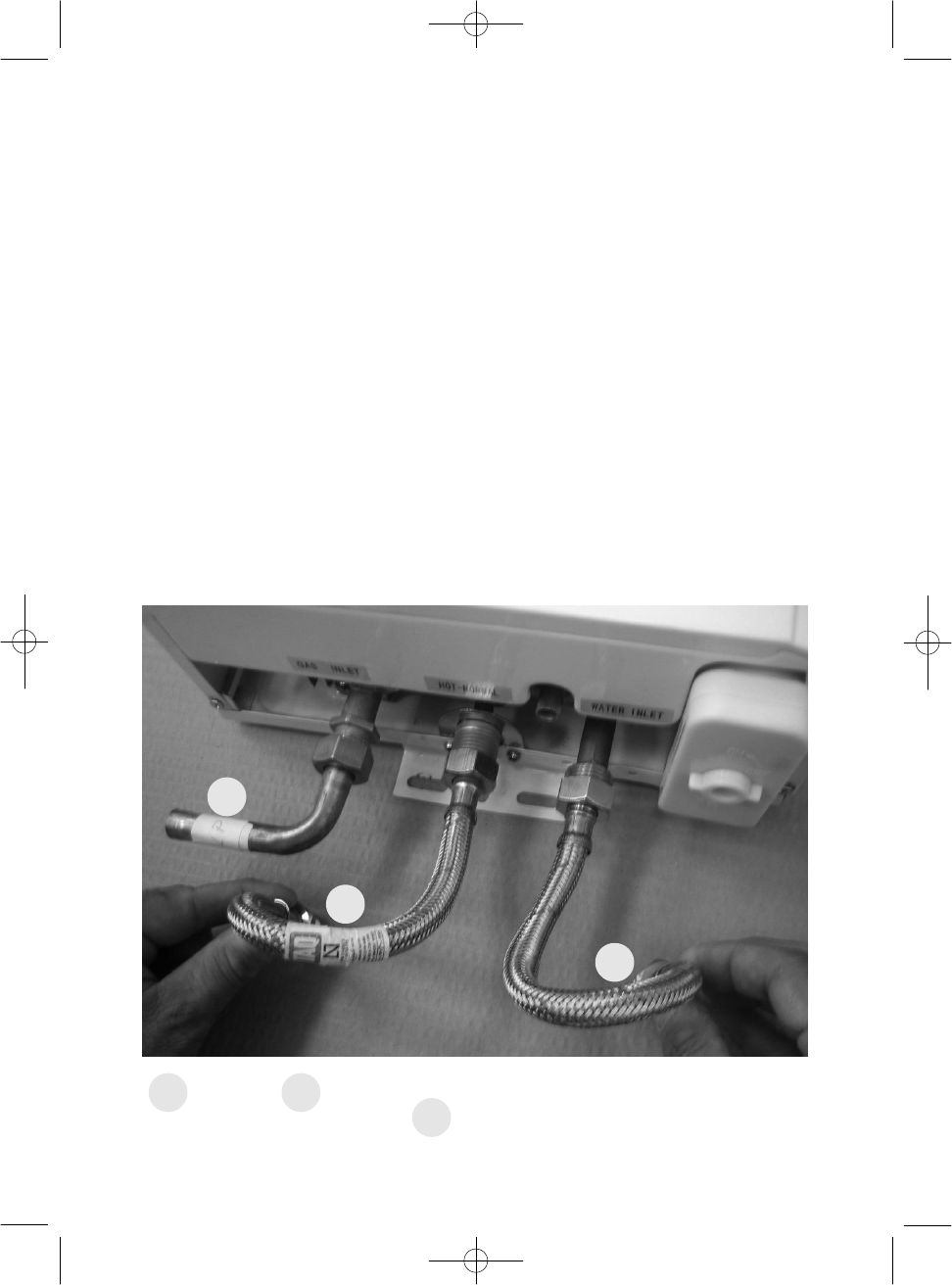
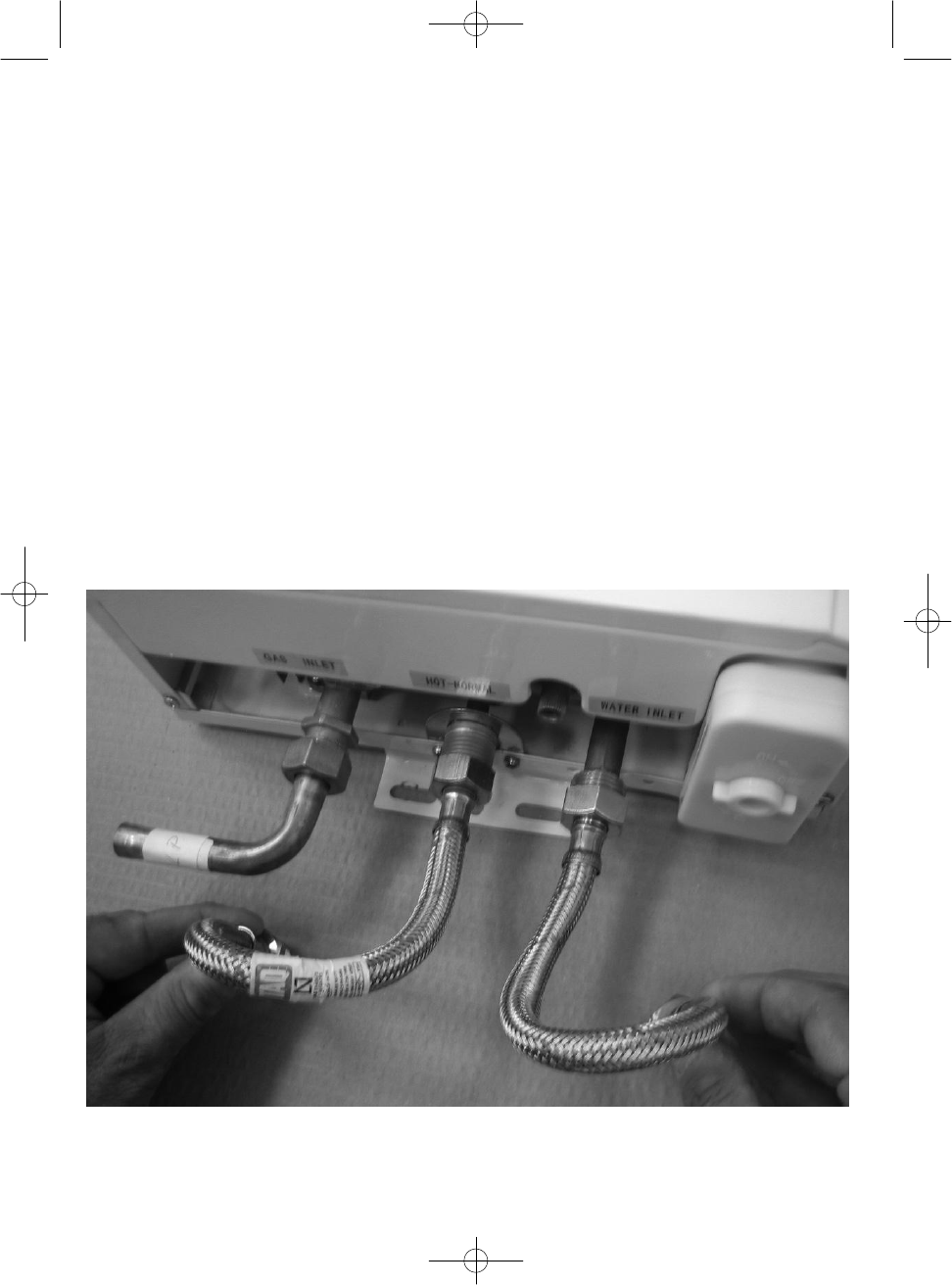
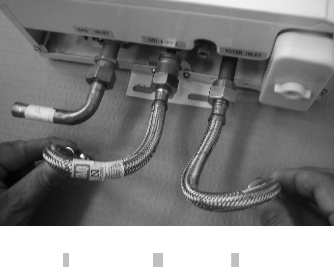
2.5. Water heater water connections.
2.5.1. To make installation easier or replace previous models, the water heaters have been equipped
with flexible hoses.
2.5.2. Connect the flexible hoses according to the following directions:
- Female-Female flexible hose is used to connect the cold water inlet with the water heater inlet.
- Male-Female flexible hose is used to connect the hot water inlet with the water mains.
2.5.3. All connections shown are carried out with R 1/2” screw.
2.5.4. Make sure the joints are tightened properly.
G
H
C
C
Cold
H
Hot
G
Gas
9
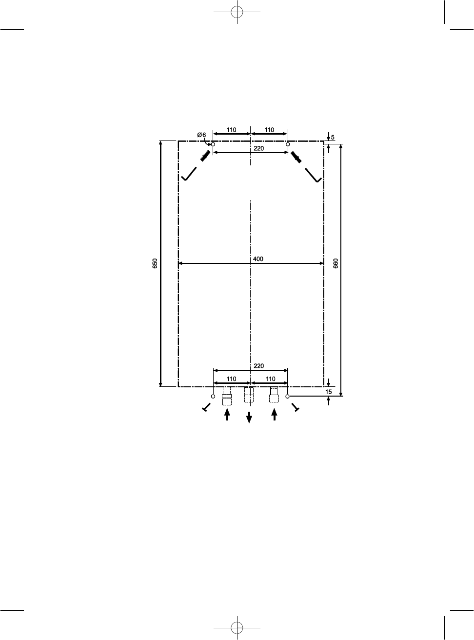
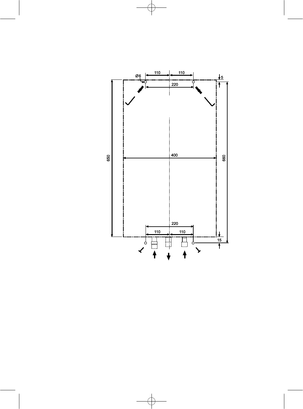
3.
POSITIONING.
- For correct operation of the heater, install it in a vertical position.
- Use the mounting template included in the package. As an example, see template model 14 l / min:
- The fastening elements are in the bag of accessories included in the water heater packaging (wall
plugs for fixing upper and lower fixing screws)
- Hang the water heater of hooks and tighten the screws to attach it to the wall.
- Connect the flexible hot and cold water hoses without forgetting to check for leaks. Do not
remove the filter at the cold water inlet in order to avoid circulation problems.
OPTIMA14
Clod
water
inlet
Hot
water
outlet
Gas
inlet
10
4. EVACUATION OF BURNT GAS
4.1. Evacuation of burnt gas pipe.
The burnt gas evacuation pipe must have the following diameters, depending on model:
• Models COB 5 and COB 5 x can only be attached to one of the two following types of combustion product
evacuation pipes:
1º. If you choose an Ø 80 mm pipe for the evacuation, the pipe joining the cutter will be adjusted “to the bottom” in
the inside of the water heater’s casing.
2º. If the Ø 100 pipe is chosen to evacuate the combustion products, the coupler must be installed. Ø 80 to Ø 100
supplied with the water heater. The Ø 80 area will be fitted “to the bottom in the inside of the casing of the water
heater’s draught diverter; the Ø 100 pipe of the duct will be adjusted from the inside and to the bottom of the
Coupler".
• Models COB 10 and COB 10 x.
Pipe for fitting the draft diverter on the inside. Ø 110 mm.
Pipe for fitting on the outside. Ø 120 mm.
Couplings for draft diverters are found at specialist trade stores.
• Model COB 14.
Pipe for fitting the draft diverter: Ø130 mm
4.2. The mass flow rates for calculating flues are found in the table on page 11.
4.3. Ensuring the correct evacuation of combustion gases.
To ensure the system is functioning with the water heater’s nominal power, check the tightness of the whole
combustion gas evacuation system through a spray plate, cooled mirror or any other approved apparatus,
4.4. Maintenance.
Recommended on an annual basis. This must be carried out by an Official Technical Service.
5. MOUNTING THE COVER.
If for any reason you need to remove the cover for installation:
5.1. Remove the gas knob and temperature selector by pulling them out.
5.2. Loosen the screws connecting the cover.
5.3. Assemble the controls by pressing them inwards.
CHECK AND COMMISSIONING
- Ensure that the installation meets on ALL REQUIREMENTS OF THE REGULATIONS IN FORCE IN THE COUNTRY IN
WHICH THIS INSTALLED.
- Check the complete sealing of the gas and water circuits.
- Turn on the heater and check its operation for 15 min, teach the user the proper handling and use of heater and
give this instruction manual
11
6. CONTROL DEVICE FOR THE EVACUATION OF GASES (T.T.B.)
6.1. The T.T.B. safety element that is fitted to the water heaters ensures that combustion products are
evacuated properly and should, therefore, not be deactivated and uncontrolled interventions should
not be performed on it. In case of disturbances in the evacuation of combustion products the device
interrupts the gas supply to the burner.
6.2. If the T.T.B. device is activated once the water heater is turned on, revise the burnt gas outlet by checking the
evacuation with a cooled mirror with running water, or any other measuring device approved for this purpose.
6.3. In case of damage, use only original spare parts as the T.T.B. device may not work properly
otherwise.
6.4. The T.T.B. device should be replaced by experts as follows:
- Remove the defective T.T.B. device by loosening the two screws holding it together.
- Remove the thermocouple.
- Insert a new original thermocouple.
- Attach the T.T.B. device to the smoke box without forcing the screws.
- Check it is working properly.
6.5. Models for “Exclusive outside installation” do not need this device.
VERY IMPORTANT
In the premises where the water heater is located, do not forget to open the air inlet
and, where appropriate, the air outlet as per the requirements of the GAS Installations Regulations.
To maintain a clean Environment, remember to dispose of used batteries in containers
prepared for collecting these products.
MASS FLOW RATES OF P.D.C.
(UNE-EN 26 5.2.1.4 b)
GAS
5-
litre Models
10-
litre Models
14-
litre Models
Qn
Qm
Qn
Qm
Qn
Qm
g/s
g/s
g/s
g/s
g/s
g/s
G20
7,5
6,3
16,1
12,5
21,5
16,3
G30
7,1
5,9
15,1
11,7
20,2
15,3
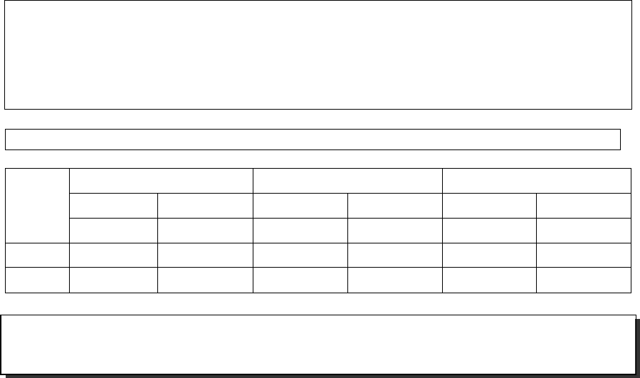
12
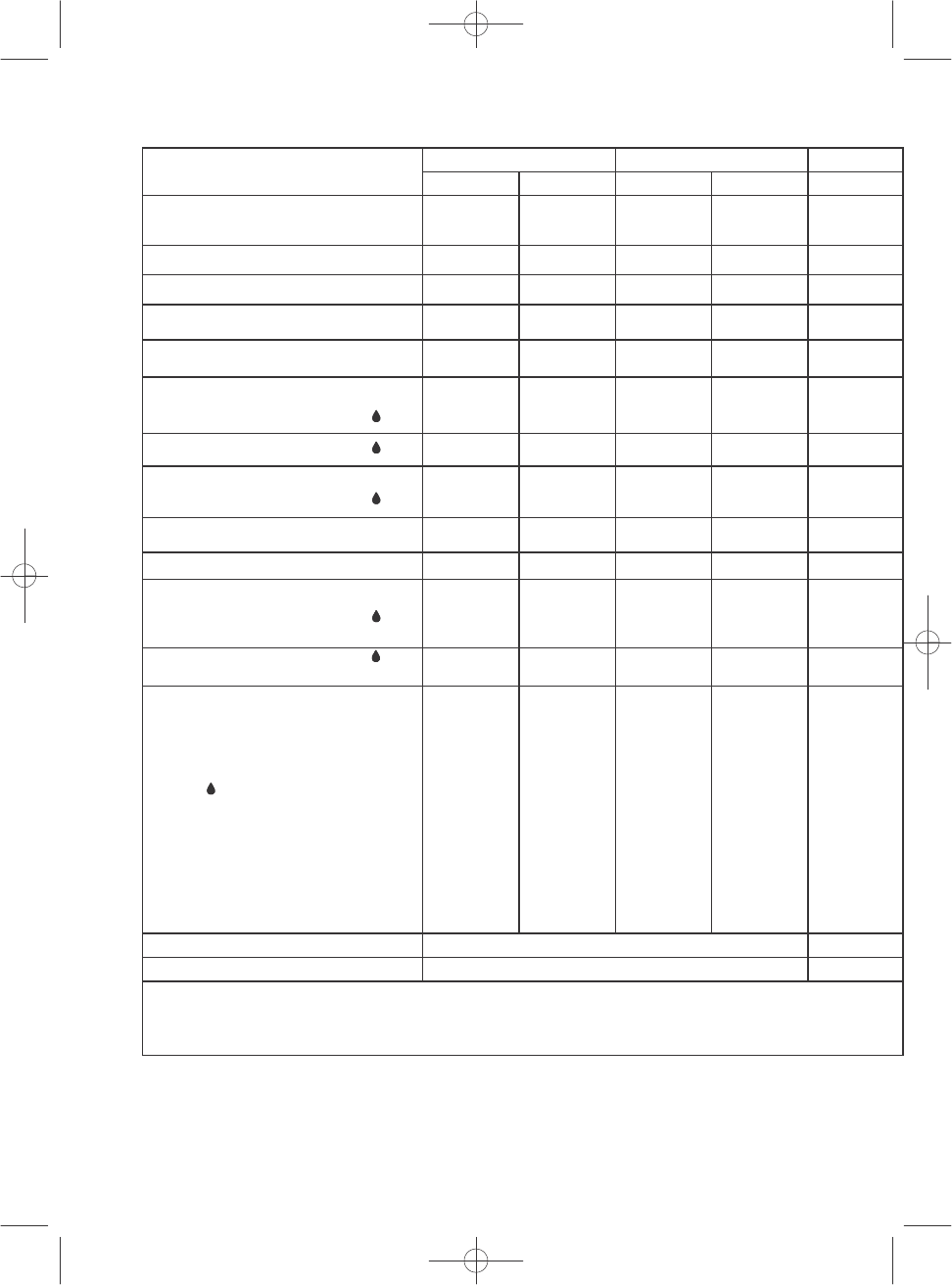
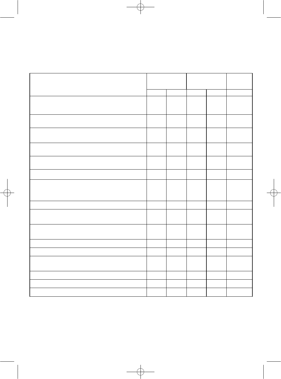
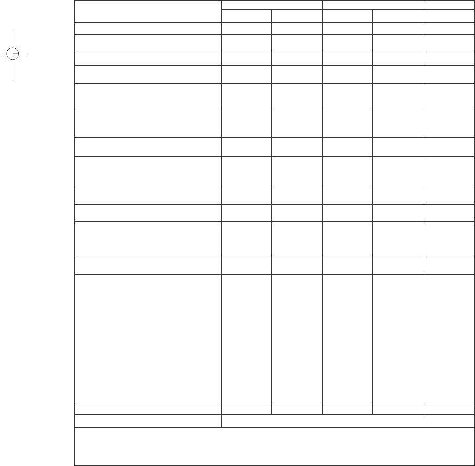
TECHNICAL SPECIFICATIONS
TECHNICAL SPECIFICATIONS
5
LITRES
10
LITRES
14
LITRES
COB 5
COB 5
x
COB 10
COB 10
x
COB 14
CATEGORY
I
I
2H3+
I
I
2H3+
I
I
2H3+
I
I
2H3+
I
I
2H3+
APPLIANCE TYPE
B
11BS
B
11
B
11BS
B
11
B
11BS
TYPE OF INSTALLATION
Inside
Outside
Inside
Outside
Inside
NOMINAL CONSUMPTION
–
kW min.
Max.
4,10
10.1
4,10
10.1
8,10
20.2
8,102
0.2
10,70
26,8
USEFUL POWER
-
kW
minimum
maximum
3,6
8.9
3,6
8.9
7,10
17.8
7,101
7.8
9,3
23,8
WATER
(l/min) AND
TEMPERATURE RATE:
(a)
40º
C
(
∆
=
25°
C)
—
5.1
—
5.1
—
10.1
—
10.1
—
13,7
65º
C
(
∆
=
50°
C)
—
2.6
—
2.6
—
5.1
—
5.1
—
6,8
MINIMUM WATER PRESSURE
(
b
a
r
) FOR
TEMPERATURE:
(b)
40º
C
(
∆
=
25°
C)
—
0.5
—
0.5
—
0.5
—
0.5
—
0,4
65º
C
(
∆
=
50°
C)
—
0.2
—
0.2
—
0.2
—
0.2
—
0,2
MAXIMUM WATER PRESSURE
(
b
a
r
)
(
d
)
10
10
10
10
10
GAS CONSUMPTION
(
1013
m
b
ar
/
288°
K
)
(
c
)
Propane
G-31
kg/h
Butane
G-30
0.32
0.79
0.32
0.79
0.63
1.58
0.63
1.58
0,84
2,09
N
atural gas
G-2
0
m
3
/h
0
.
43
1
.
07
0
.
43
1
.
07
0
.
86
2
.
14
0
.
86
2
.
14
1,13
2,83
GAS PRESSURE (mbar)
At the heater inlet
(mbar) Butane
G-
30
Propane
G-31
Natural
G-20
In the burner
-
Maximum
Power
(
)
(mbar)
Butane
G-30
Propane
G-31
Natural
G-20
In the burner
-
Minimum power
(
)
(mbar)
Butane
G-30
Propane
G-31
Natural
G-20
28-30
37
20
27.3
35.3
14.7
—
—
—
28-30
37
20
27.3
35.3
14.7
—
—
—
28-30
37
20
27.57
35.84
13.33
—
—
—
28-30
37
20
27.57
35.84
13.33
—
—
—
28-30
37
20
27,57
35,84
13,33
—
—
—
E
L
E
CT
R
I
C
AL CURRENT
(
220
V
—
50
H
z
)
no
no
no
no
no
“EC” MARK
0461CN0998
0461BT0927
(a)
Based on input temperature of cold water at 15º C.
(b) This is the pressure required to operate the appliance, allowing for the addition of what is needed based on diameters and length of the pipeline circuit used.
(c)
This consumption is produced in reference conditions for an 84% yield of the IPC
(d)
Maximum pressure with water temperature of 7
5º
C.
13
PREVENTIONS
AGAINST LIME
In specific areas with hard water, in order to prevent the deposition of lime that can affect to the heat trasnmission, it is
recommended to limit the output temperature adjusting it by means of the temperature selector.
AGAINST ICE
In specific cold areas, to prevent the water haeter from being damaged as result of an inminent freeze:
-
Close the water inlet valve to the heater
-
Open the lowest hot water tap (e.g. the bidet)
-
Open the drain valve in the lower part of the heater, so that water can come out and the air can enter.
MAINTENANCE
Use a cloth with soapy water to clean the front cover, avoid abarsive detergents and solvents. To increase the life of your water
heater, it should be maintained and cleaned once a year, please call our Technical Service.
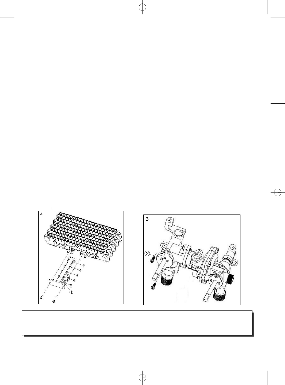
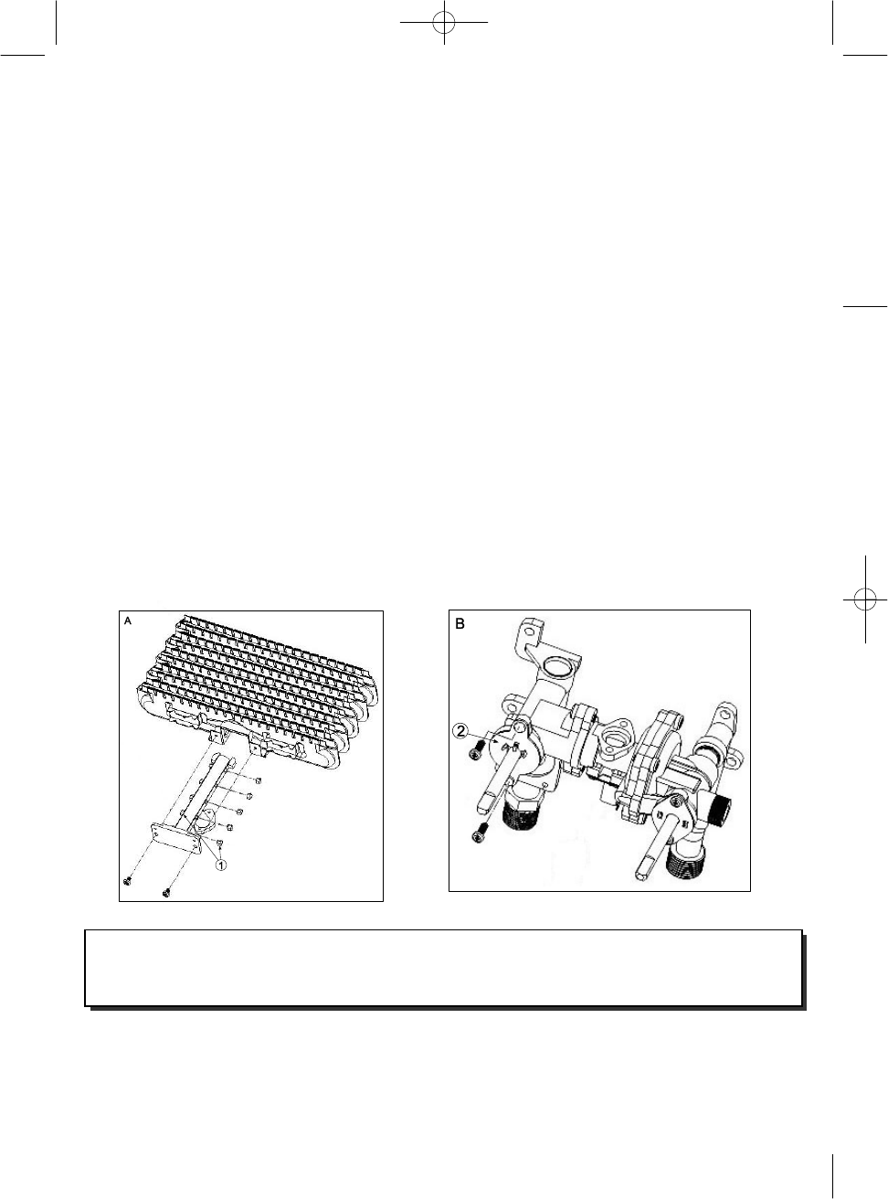
ADAPTING TO DIFFERENT GASES
The gas water heater is equiped for a specific gas. Adaptation of COINTRA gas water heaters to a different gas of the gas
prepared from factory, must be performed by competent authorized using COINTRA oiriginal parts and in accordance with the
regulations in force in the country in which the appliance is installed. This adaptation should be as follows:
1.
Turn off the water and gas supply, remove the knobs and put off the front cover.
2.
Replace the injector nozzles (see figure A) in the burner by those specific for the corresponding gas.
3.
Replace the gas front valve mechanism (figure B), paying attention to mount it correctly..
4.
Place the new technical data sticker on the previous one, to show the right gas adaption.
VERY IMPORTANT: The adjusting screw of minimum flow, situated in the body of water, which is
sealed will not be manipulated in any way.
14
INJECTOR DIAMETER TABLES
5 l/min MODELS.
MODELS
COB 5
and
COB 5
x
G.P.L.
G.N.
INJECTORS
DIAMETER
0.66
1.0
CODE
10 l/min MODELS.
MODELS
COB 10
and
CO
B10
x
G.P.L.
G.N.
INJECTORS
DIAMETER
0.72
1.15
CODE
14 l/min MODELS.
MODELS
COB 14
G.P.L.
G.N.
INJECTORS
DIAMETER
0.66
1.02
CODE
WIRING OUTLINE OF WÁTER HEATERS WITHOUT PILOT LIGHT
15
CERTIFICATE OF GUARANTEE - COINTRA GODESIA
COINTRA guarantees the appliances that it supplies in accordance with Act 23/2003 relating to guarantees when
selling consumer goods for a period of two years against any non-compliance that becomes apparent after
product delivery.
Unless proved otherwise, it is presumed that non-conformities that become apparent six months after delivery did
not exist when the goods were delivered
Spare parts will be guaranteed for a period of two years from the date the appliance is delivered. With the
exception of the heat exchanger (radiator), which is guaranteed for three years.
This guarantee is only valid for appliances sold and installed in Spanish territory.
SCOPE OF GUARANTEE
Unless proved otherwise, it is understood that the goods are compliant and suitable for the purpose for which they
are purchased provided the below conditions are met:
- The guaranteed appliance must correspond to one which the manufacturer specifically intends for Spain
and must be installed in Spain.
- Any parts that must be replaced will be determined by our OFFICAL Technical Support team, and will
always be Cointra original parts
- The guarantee is valid provided that normal maintenance operations are carried out as described in the
technical instructions supplied with the equipment.
- The consumer must inform Cointra that the goods are non compliant within two months of becoming
aware of this.
The guarantee does not cover incidents produced by:
- The electrical supply of the equipment through power generators or any other system that is not a stable
power grid with sufficient capacity.
- Products that have been repaired by any party other than Cointra’s OFFICIAL Technical Support team
and/or Cointra Godesia authorised staff.
- Corrosion, distortion, etc. caused by improper storage.
- Handling of the product by any party other than Cointra during the guarantee period.
- Assembly that is not in accordance with the instructions provided with the equipment.
- Equipment installation that does not respect prevailing Laws and Regulations (electricity, water, etc.).
- Defects in the electrical or water facilities, or insufficient flow, etc.
- Anomalies caused by improper treatment of water supplied to the equipment, corrosion caused by its
aggressiveness, badly carried out anti-scaling treatments, etc.
- Anomalies caused by the weather (ice, lightening, floods, etc.) as well as by erratic currents.
Due to improper maintenance, neglect or misuse.
The material replaced under the guarantee will be the property of COINTRA GODESIA
NOTE: You must complete all the information outlined in the Guarantee Certificate. The guarantee must be
validated immediately by indicating the date and sending it to COINTRA GODESIA
Each member of our OFFICIAL Technical Support team has the corresponding accreditation from Cointra. Demand
this accreditation in any dealings.
Any claims must be made to the competent authority in this matter.
16
Avda.
Italia,
2
(Edificio
Ferroli)
-
28820
Coslada
(Madrid)
-
ESPAÑA
Tel.:
+34
916
707
459.
Fax:
+34
916
708
683
S.A.T.
Tel.:
902
402
010
E-mail:
info@cointra.es
Cointra
Godesia,
S.A. reserves the right to modify, at any time and without prior notice, the data and characteristics of the devices in this document.
Member of Anfel (National Association of electrodomestic manufacturers).
Gebruikershandleiding.com neemt misbruik van zijn services uitermate serieus. U kunt hieronder aangeven waarom deze vraag ongepast is. Wij controleren de vraag en zonodig wordt deze verwijderd.
Product:
Spelregels forum
Om tot zinvolle vragen te komen hanteren wij de volgende spelregels:
lees eerst de handleiding door;
controleer of uw vraag al eerder door iemand anders is gesteld;
probeer uw vraag zo duidelijk mogelijk te stellen;
heeft u een probleem en al geprobeerd om dit op te lossen, vermeld dit erbij aub;
heeft u een oplossing gekregen van een bezoeker dan horen wij dat graag in dit forum;
wilt u een reactie geven op een vraag of antwoord, gebruik dan niet dit formulier maar klik op de knop 'reageer op deze vraag';
uw vraag wordt direct op de website gezet; vermijd daarom persoonlijke gegevens in te vullen;
Belangrijk! Als er een antwoord wordt gegeven op uw vraag, dan is het voor de gever van het antwoord nuttig om te weten als u er wel (of niet) mee geholpen bent! Wij vragen u dus ook te reageren op een antwoord.
Belangrijk! Antwoorden worden ook per e-mail naar abonnees gestuurd. Laat uw emailadres achter op deze site, zodat u op de hoogte blijft. U krijgt dan ook andere vragen en antwoorden te zien.
Abonneren
Abonneer u voor het ontvangen van emails voor uw Cointra Optima COB 5x bij:
nieuwe vragen en antwoorden
nieuwe handleidingen
U ontvangt een email met instructies om u voor één of beide opties in te schrijven.
Ontvang uw handleiding per email
Vul uw emailadres in en ontvang de handleiding van Cointra Optima COB 5x in de taal/talen: Engels, Frans, Portugees, Spaans als bijlage per email.
De handleiding is 2,33 mb groot.
U ontvangt de handleiding per email binnen enkele minuten. Als u geen email heeft ontvangen, dan heeft u waarschijnlijk een verkeerd emailadres ingevuld of is uw mailbox te vol. Daarnaast kan het zijn dat uw internetprovider een maximum heeft aan de grootte per email. Omdat hier een handleiding wordt meegestuurd, kan het voorkomen dat de email groter is dan toegestaan bij uw provider.
Uw handleiding is per email verstuurd. Controleer uw email
Als u niet binnen een kwartier uw email met handleiding ontvangen heeft, kan het zijn dat u een verkeerd emailadres heeft ingevuld of dat uw emailprovider een maximum grootte per email heeft ingesteld die kleiner is dan de grootte van de handleiding.
Er is een email naar u verstuurd om uw inschrijving definitief te maken.
Controleer uw email en volg de aanwijzingen op om uw inschrijving definitief te maken
U heeft geen emailadres opgegeven
Als u de handleiding per email wilt ontvangen, vul dan een geldig emailadres in.
Uw vraag is op deze pagina toegevoegd
Wilt u een email ontvangen bij een antwoord en/of nieuwe vragen? Vul dan hier uw emailadres in.